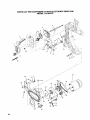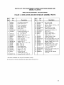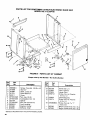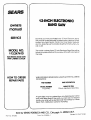
1
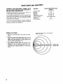
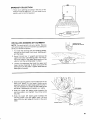
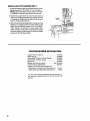
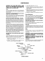
f
Save This Manual
For Future Reference
SEARS
owners
monuol
MODEL NO.
113.247410
ELECTRONIC BAND SAW
WITH CABINET & DOOR
S_rial
Number
Model and s_rial nunnb_rs
may b_ found at the
I_t-hand side of the bas_.
You should record both
model and s_rial number
in a safe place for future
US_.
CRRFTSMRN
12-1NCH ELECTRONIC
BAND SAW
CAUTION:
READALL
INSTRUCTIONS
CAREFULLY
• assembly
• operating
• repair pads
J
Sold by SEARS,ROEBUCKAND CO., Chicago,
Part No. SP5085
IL.60684 U.SA.
FULL ONE YEAR WARRANTY
ON CRAFTSMAN
BAND SAW
If within one year from the date ol purchase, this Craftsman Band Saw fails due to a defect in material or workmanship,
Sears will repair it, free of charge.
WARRANTY
SERVICE
CENTER/DEPARTMENT
IS AVAILABLE
BY SIMPLY
CONTACTING
THROUGHOUT
THE UNITED STATES.
THE
NEAREST
SEARS
SERVICE
This warranty applies only while this product is used in the United States.
This warranty gives you specific legal rights and you may also have other rights which vary from state to state.
SEARS, ROEBUCK
GENERAL
SAFETY
AND CO., DEPT. 698/731A Sears Tower, Chicago, IL 60684
INSTRUCTIONS
1. KNOW YOUR POWER TOOL
Read and understand
the owner's
manual
and
labels affixed
to the tool. Learn its application
and limitations as well as the specific potential
hazards peculiar to this tool.
2. GROUND
ALL TOOLS
This
tool
is equipped
with
an approved
3-conductor
cord and a 3-prong grounding type
plug to fit the proper grounding type receptacle.
The green conductor
in the cord is the grounding
wire. Never connect the green wire to a live
terminal.
3. KEEP GUARDS IN PLACE,
in working order, and in proper adjustment and
alignment.
4. REMOVE ADJUSTING KEYS AND WRENCHES
Form habit of checking to see that keys and
adjusting wrenches are removed from tool before
turning it on.
5. KEEP WORK AREA CLEAN
Cluttered areas and benches invite accidents.
Floor must not be slippery due to wax or sawdust.
6. AVOID DANGEROUS ENVIRONMENT
Don't use power tools in damp or wet locations or
expose them to rain. Keep work area well lighted.
Provide adequate surrounding work space.
7. KEEP CHILDREN AWAY
All visitors should be kept a safe distance from
work area.
8. MAKE WORKSHOP CHILD-PROOF
-- with padlocks, master switches, or by removing
starter keys.
9. DON'T FORCE TOOL
It will do the job better and safer at the rate for
which it was designed.
10. USE RIGHT TOOL
Don't force tool or attachment to do a job it was
not designed for
11. WEAR PROPER APPAREL
Do not wear loose clothing, gloves, neckties or
jewelry (rings, wrist watches) to get caught in
moving parts. Nonslip footwear is recommended.
Wear protective hair covering to contain long
hair. Roll long sleeves above the elbow.
12. USE SAFETY GOGGLES (Head Protection)
Wear Safety goggles (must comply with ANSI
2
13.
14.
15.
16.
17.
18.
19.
FOR POWER
TOOLS
Z87.1) at all times. Everyday eyeglasses only
have impact resistant
lenses, they are NOT
safety glasses. Also, use face or dust mask if
cutting operation is dusty, and ear protectors
(plugs or muffs) during extended periods of
operation.
SECURE WORK
Use clamps ora vise to hold work when practical.
It's safer than using your hand, and frees both
hands to operate tool.
DON'T OVERREACH
Keep proper footing and balance at all times.
MAINTAIN TOOLS WITH CARE
Keep tools sharp and clean for best and safest
performances. Follow instructions for lubricating
and changing accessories.
DISCONNECT TOOLS
before servicing;
when changing accessories
such as blades, bits, cutters, etc.
AVOID ACCIDENTAL STARTING
Make sure switch is in "OFF" position before
plugging in.
USE RECOMMENDED
ACCESSORIES
Consult the owner's manual for recommended
accessories. Follow the instructions that accompany the accessories. The use of improper accessories may cause hazards.
NEVER STAND ON TOOL
Serious injury could occur if the tool is tipped or
if the cutting tool is accidentally contacted. Do
not store materials above or near the tool such
that it is necessary to stand on the tool to reach
them.
20. CHECK DAMAGED PARTS
Before further use of the tool, a guard or other
part that isdamaged should be carefully checked
to ensure that it will operate properly and perform
its intended function.
Check for alignment of
moving parts, binding of moving parts, breakage
of parts, mounting, and any other conditions that
may effect its operation. A guard or other part
that is damaged should be properly repaired or
replaced.
21. NEVER LEAVE TOOL RUNNING UNATTENDED
Turn power off. Don't leave tool until it comes to
a complete stop.
additional safety instructions for band saw
Safety is a combination of common sense, staying
alert, and knowing how your band saw works.
BEFORE
USING
and lock knob, lower blade guide, tension adjusting knob and tension scale, and blade thrust
bearing adjustment.
THE SAW:
3. Read and understand
operating procedures
WARNING: TO AVOID MISTAKES THAT COULD
RESULT IN SERIOUS, PERMANENT INJURY, DO
NOT PLUG THE SAW IN UNTIL THE FOLLOWING
STEPS
HAVE
BEEN
SATISFACTORILY
COMPLETED:
1. Assembly
all safety instructions and
throughout the manual.
4. Read the following labels which appear on the
top of the band saw and blade guard.
and alignment.
2. Learn the function and proper use of the on-off
switch, bevel crank and lock, upper blade guide
IDANGERI
• Always
wear safety
with ANSI Z87.1.
goggles
• Before
turning
saw on, check
a) Blade Tension
b) Blade
c) Thrust
Bearings
that comply
and adjust:
Guides
FOR YOUR OWN SAFETY:
• Before
BLADE
turning
GUIDE
saw on, adjust
UPPER
to just clear workpk_ce.
• Support,
fixture
or brace workpi_e
firmly
against tlNble so it will not rock
or twist
from your hand,
Know
This
Tool!
Read
• Plan hand positions
won't cause
injury,
and
Understand
so a sudden
• Turn saw Off and wait for bisde
before freeing
jammed
material,
INSTALLING
OR MOVING
1. To avoid injury from unexpected
saw movement:
b. Adjust the saw so the table is level and the saw
does not rock.
c. Bolt the saw to the floor if it tends to slip, slide,
or tip over during operations like cutting long,
heavy boards.
cord before
2. Store and use the band saw indoors.
BEFORE
before
Using
this
to stop
changing
b_ad_s or leaving
etoe.
• Maintain
V,e" maximum
¢kmrsnce
table and sanding
belt.
Machine.
and wait
Mw,
YOUR
THE
available at Sears retail or catalog stores. Use
of glasses or use of goggles not in compliance
with ANSI Z87.1 could result in severe injury
from breakage of the eye protection.
a. Place the saw on a firm level surface where
there is plenty of room for feeding the workpiece.
d. Turn saw off and unplug electric
moving the saw to a new area.
Manual
• Turn saw off, m/hove
switch
key,
for b_lKle to Ito_ before
ad_uatlt_g
WEAR
WHEN
SAW
Owner's
slip
C.
For dusty operations,
with safety goggles.
d Use extra caution with large, very small, or
awkward workpieces.
1. Use extra supports (tables, saw horses,
etc.) for any workpieces large enough to tip
when not held down to the table top.
,
Do not feed small pieces that require your
finger holding the workpiece to go under
the guard area. Use jigs or fixtures to hold
the work and keep your hands away from
the blade.
,
When cutting irregularly
shaped workpieces, plan your work so it will not pinch
the blade. A piece of molding, for example,
must lay flat or be held by a fixture or jig that
will not let it twist, rock or slip while being
cut.
.
Properly support round material such as
dowel rods, or tubing. They have a tendency
to roll while being cut, causing the blade to
"bite." To avoid this, always use a "V" block,
or clamp the workpiece to a miter gage.
EACH USE
1. Inspect your saw. If any part of this band saw is
missing, or bent, or failed in any way, or any
electrical components do not work properly, turn
the saw off, remove switch key, and unplug the
saw. Replace damaged, missing, or failed parts
before using the saw again.
2. Plan your work to protect you r eyes, hands, face,
ears and body.
a. Do not do layout, assembly, or set up work on
the table while the saw is running.
b. Wear safety goggles (not g lasses) that com ply
with ANSI Z87.1 (shown on package). Using
any power tool can result in foreign objects
being thrown into the eyes, which can result in
permanent eye damage. Safety goggles are
wear a face shield along
e. To avoid risk of hearing damage, wear ear
plugs or muffs during extended periods of
operation.
3
additional
safety
f. To avoid being suddenly caught in the blade:
1. Do not wear gloves.
2. Remove all jewelry and loose clothing.
3. Tie back long hair.
4. Roll long sleeves above the elbow.
g. To avoid injury from accidental starting, always
unplug saw, turn switch off and remove switch
key before removing the guard, installing or
removing any blade, accessory or attachment,
or making any adjustments.
instructions
WHENEVER
2. Make sure the blade teeth point downward
toward the table.
3. Make sure the blade tracking guides
thrust bearings are properly adjusted.
4. Always check and correctly
sanding belt tension.
a.
if your saw makes unfamiliar
noise or if it
vibrates
excessively,
stop immediately.
Turn
thesaw off. remove switch key and unplug the
saw. Do not restart until finding and correcting the problem.
b.
Avoid awkward hand positions where a sudden
slip could cause a hand to move into the blade
or the sanding belt.
c.
Feed the workpiece
only fast enough to let the
blade cut without bogging
down.or binding.
d.
Before freeing jammed material, turn saw off.
Remove switch key. Remove plug from power
source outlet. Wait for all moving parts to stop.
e.
When
backing
up the workpiece,
the blade
may bind in the kert (cut). This is usually
caused
by sawdust
clogging
up the kerf or
because the blade comes out of the guides. If
this happens:
and
adjust blade or
i. To avoid accidental blade contact, minimize
blade breakage and provide maximum blade
support.
1. Turn saw off.
1. Always adjust the upper blade guide and
blade guard to just clear the workpiece.
2_ Unplug
3. Remove
2. Plan your hand placement so your fingers
will not be where a sudden slip could cause
them to hit the blade.
k. To avoid an electrical shock, make sure your
fingers do not touch the metal prongs on the
plug when installing or removing the plug to or
from a live outlet.
I. Never turn your band saw "ON" before clearing
everything except the workpiece and related
feed or support devices off the table.
BEFORE SANDING
1. Keep the table and sanding belt adjusted so the
gap between them is no more than 1/16-inch
wide.
2. To avoid fire, shock, or cause electrical shorts,
do not sand metal. It could ignite the sawdust
inside the saw.
saw.
switch
key.
4. Wait for all moving
5. Remove
Make sure all clamps and locks are tight and
there is no excessive play in any parts.
j,
IS RUNNING
WARNING:
DO NOT
ALLOW
FAMILIARITY
(GAINED
FROM FREQUENT
USE OF YOUR
BAND
SAW) TO CAUSE A CARELESS
MISTAKE.
ALWAYS
REMEMBER
THAT A CARELESS
FRACTION
OF A SECOND
IS SUFFICIENT
TO INFLIC SEVERE INJURY.
h. To avoid slips and jams causing injury:
1. Choose the right size and style blade for the
material and the type of cutting you plan to
do. Use this band saw to cut and sand only
wood, wood like products and plastic.
SAW
parts
to stop.
band saw cover.
6. Stick a flat blade screwdriver
the kerf.
7. Turn the upperwheel
up the workpiece.
f°
or wedge
into
by hand while backing
Before removing
loose pieces from the table,
turn saw off and wait for all moving parts to
stop.
ACCESSORIES
To avoid injury from untested or improper accessories,
use only Recommended Accessories listed
on the Accessory page of this manual.
table of contents
Page
2
3
3
3
3
4
4
4
5
6
6
6
7
7
7
8
10
10
12
14
14
15
15
16
17
17
General Safety Instructions for Power Tools .......
Additional Safety Instructions for Band Saw .......
Before Using the Saw ........................
When Installing or Moving the Saw ............
Before Each Use ............................
Before Sanding .............................
Whenever Saw is Running ....................
Accessories ................................
Glossary of Terms for Woodworking .............
Electrical Connections .........................
Power Supply ...............................
Motor Safety Protection .......................
Wire Sizes .................................
Unpacking and Checking Contents ..............
Tools Needed ..............................
Table of Loose Parts .........................
Assembly and Alignment .......................
Assembling Cabinet .........................
Mounting the Motor ..........................
Selecting Blade Speed .......................
Recommended Speed Settings ...............
Connecting the Motor ........................
Mounting the Saw to the Cabinet ..............
Mounting Door ..............................
Attaching Trim Caps and Trim Ledge ...........
Attaching Handwheel ........................
glossary
cutting
operation
through
the face of the
Crosscut
A cutting
workpiece.
operation
made
across
Compound
Cutting
A simultaneous
bevel and miter
the width
of the
A sticky, sap based
Used
in reference
to surface
Freehand (as used for band saw)
Performing
a cut without
the workpiece
supported
on the work table.
speed
properly
sap based
residue
from
wood
Ripping
A cutting
piece.
operation
Sawblade
Path
substance
or workpiece
The distance
the tip of the saw blade
outward
from the face of the blade.
Kerf
directly
in
cut
or
tooth
is bent
Trailing End
The workpiece
end last cut by the saw blade.
Workpiece
Leading End
The end of the workpiece
cutting tool first.
which
Mitering
An angle cutting
the workpiece.
made across
operation
of the work-
Set
products.
The material
removed by the blade in a through
orthe slot produced
bythe blade in a non-through
partial cut.
of the
that has dried.
along the length
The area of the worktable
line with the saw blade.
Gum
A sticky,
Resaw
Resin
operation.
FPM
Feet per minute.
of blade.
19
19
19
19
20
21
22
24
27
27
27
27
27
28
28
29
29
30
30
31
31
31
32
36
Push Stick
A device used to feed the workpiece through the saw
during narrow ripping type operations so the operator's hands are kept well away from the blade.
A cutting operation
to reduce the thickness
workpiece to make thinner pieces.
cutting
18
of terms for woodworking
Beveling
An angle
board.
Page
Getting to Know Your Band Saw ................
Location and Function of the Electronic
Indicator System ..............................
Digital Readout Display ......................
Function Keys ..............................
Battery Cover ...............................
Using the Electronic Indicator System ..........
Installing the Blade ..........................
Aligning the Blade and Blade Guides ...........
Mounting the Front Table .....................
Squaring the Blade to the Table ...............
Location and Function of Controls ...............
On-Off Switch ..............................
Tilting Head for Bevel Cut ....................
Adjusting Bevel Lock Knob ...................
Basic Band Saw Operation .....................
Circle Cutting ...............................
Sawdust Collection ..........................
Installing Sanding Attachment .................
Installing the Sanding Belt ....................
Recommended Accessories ..................
Maintenance .................................
Adjusting Band Saw Bevel Travel ..............
Adjusting Upper Blade Guide Travel ...........
Trouble Shooting ..............................
Repair Parts ..................................
is pushed
into the
the width
of
The item on which the cutting operation is being
performed. The surfaces of a workpiece or common ly
referred to as faces, ends, and edges.
Worktable
The surface on which the workpiece
rests while
performing a cutting or sanding operation.
electrical
POWER
SUPPLY
Motor Specifications
The AC motor used in this saw is a capacitor-start,
non-reversible type having the following specifications:
MODEL NO.
113.247410
Rated H. P ....................................
5/8
Maximum Developed H.P ...................
1-1/8
Voltage .....................................
120
Amperes ....................................
7.9
Hertz (Cycles) ...............................
60
Phase ....................................
Sing le
RPM ......................................
1725
Rotation of Shaft ......................
Clockwise
WARNING: TO AVOID ELECTRICAL HAZARDS,
FIRE HAZARDS, OR DAMAGE TO THE TOOL, USE
PROPER CIRCUIT PROTECTION. YOUR SAW IS
WIRED AT THE FACTORY FOR 120V OPERATION.
CONNECTTO A 120V, 1S-AMP, BRANCH CIRCUIT
AND USE A 15-AMP FUSE OR CIRCUIT BREAKER.
TO AVOID SHOCK OR FIRE, IF POWER CORD IS
WORN OR CUT, OR DAMAGED IN ANY WAY,
HAVE IT REPLACED IMMEDIATELY.
IF NOT PROPERLY GROUNDED
THIS POWER
TOOL CAN CAUSE ELECTRICAL
SHOCK -PARTICULARLY
WHEN USED IN DAMP LOCATIONS CLOSE TO PLUMBING. IF AN ELECTRICAL
SHOCK OCCURS THERE IS ALSO THE POTENTIAL OF A SECONDARY HAZARD SUCH AS YOUR
HANDS CONTACTING THE SAWBLADE. NOT ALL
OUTLETS ARE PROPERLY GROUNDED. IF YOU
ARE NOT SURE THAT YOUR OUTLET IS PROPERLY GROUNDED, HAVE IT CHECKED BY A
QUALIFIEO ELECTRICIAN.
Your unit has a plug that looks like the one shown
below.
3-PRONG
PLUG
PROPERLY
GROUNDED
OUTLET
GROUNDING
PRONG
connections
WARNING: TO MAINTAIN PROPER TOOL GROUNDING WHENEVER THE OUTLET YOU ARE PLANNING TO USE FOR THIS POWER TOOL IS OF THE
TWO PRONG TYPE, DO NOT REMOVE OR ALTER
THE GROUNDING PRONG IN ANY MANNER. USE
AN ADAPTER AS SHOWN AND ALWAYS CONNECT THE GROUNDING
PRONG TO KNOWN
GROUND.
It is recommended that you have a qualified electrician replace the two prong outlet with a properly
grounded three prong outlet.
An adapter as shown is available for connecting the
plug to 2-prong receptacles. The green grounding
lead extending from the adapter must be connected
to a permanent ground such as a properly grounded
outlet box.
GROUNDING
LUG
ADAPTER
MAKE
SURE THIS IS
CONNECTED
TO A
KNOWN
GROUND
3-PRONG
PLUG
2-PRONG
RECEPTACLE
WARNING: THE ADAPTER ILLUSTRATED IS FOR
USE ONLY IF YOU ALREADY HAVE A PROPERLY
GROUNOED 2-PRONG RECEPTACLE.
MOTOR
SAFETY
PROTECTION
CAUTION: To avoid motor damage this motor should
be blown out or vacuumed frequently to keep
sawdust from interfering with normal motor venUlaUon.
1. This tool should be connected to a 120V, 15 amp
branch circuit with a 15 amp fuse or circuit
breaker. Failure to use the proper size fuse can
result in damage to the motor.
2. If the motor fails to start, turn the power switch to
the "OFF" position immediately. UNPLUG THE
TOOL. Check the saw blade to make sure it turns
freely. If the blade is free, try to start the motor
again. If the motor still does not start, refer to the
"Motor Trouble-Shooting
Chart."
3. If the motor suddenly stalls while cutting wood,
turn the power switch off, unplug the tool, and
free the blade from the wood. The motor may
now be restarted and the cut finished.
.
This power tool is equipped with a 3-conductor cord
and ground type plug listed by Underwriters' Laboratories. The ground conductor has a green jacket and
is attached to the tool housing at one end and to the
ground prong in the attachment plug at the other
end.
This plug requires a mating 3-conductor grounded
type outlet as shown above.
Frequent "blowing" of fuses or tripping
breakers may result if:
or circuit
a. MOTOR IS OVERLOADED - Overloading
occur if you feed too rapidly.
can
b. LOW
VOLTAGE - Although the motor is designed for operation on the voltage and frequency specified on the motor nameplate,
normal loads will be handled safely on voltages
not more than 10% above or below the nameplate voltage. Heavy loads, however, require
that voltage at motor terminals equals the
voltage specified on nameplate.
5. Most motor troubles may be traced to loose or
incorrect connections, overload, reduced input
voltage (such as small size wire inthe supply
circuit)
or to overly long supply circuit wire.
Always check the connections, the load and the
supply circuit whenever motor fails to perform
satisfactorily.
Check wire size and length with
the Wire Size Chart below.
overheating and motor burn-out, use the table
to determine the minimum wire size (A.W.G.)
sion cord. Use only 3-wire extension cords
have 3-prong grounding
type plugs and
receptacles which accepts the tools plug.
below
extenwhich
3-pole
CAUTION: For circuits that are farther away from
electrical service box, the wire size must be increased
proportionately in order to deliver ample voltage to
the saw motor.
Length of the
120 Volts Wire Sizes Required
Conductor
(American
Wire
0 - 25 Ft.
26 - 50 Ft.
51 - 100 Ft.
Gage
Number)
14
12
8
WIRE SIZES
The use of any extension cord will cause some loss
of power. To keep this to a minimum and to prevent
unpacking and checking contents
TOOLS
NEEDED
COMBINATION
SQUARE
MUST
STRAIGHT
EDGE
BOARD
3/4-INCH
THIS EDGE MUST
f',
j
MEDIUM
,
PE R_CTLY
SCREWDRIVER
., PHiW.s
SC.EWO.,VER
Ii_
3/8" WRENCH
7/16" WRENCH
9/16" WRENCH
COMBINATION
DRAW
LINE
LIGHT
ON
ALONG
BOARD
THIS
I
EDGE
J
SQUARE
L,_
/
7/16" SOCKET
9/16" SOCKET
1/8" HEX "L" WRENCH
5/32" HEX "L" WRENCH
OF
THICK
BE
STRAIGHT
[ ....
i
'_.:!'. ','.'_i_;',i : _iIi
BE TRUE
_
SOCKET
WRENCH
SHOULD
SQUARE
WARNING: TO AVOID INJURY FROM UNEXPECTED STARTING OR ELECTRICAL SHOCK, DO NOT
PLUG THE SAW IN UNTIL ALL ASSEMBLY AND
ALIGNMENT STEPS ARE COMPLETE. THE POWER
CORD MUST REMAIN UNPLUGGED WHENEVER
YOU ARE WORKING ON THE SAW.
Unpacking and Checking Contents
1. Separate all "loose parts" from packaging materials and check each item with "Table of Loose
Parts" to make sure all items are accounted for,
before discarding any packing material.
l
BE NO GAP OR OVERLAP
HERE WHEN
IS FLIPPED
OVER IN DOTTED
POSITION
WARNING: IF ANY PARTS ARE MISSING, DO
NOT ATTEMPT TO ASSEMBLE THE BAND
SAW, PLUG IN THE POWER CORD, OR TURN
THE SWITCH ON UNTIL THE MISSING PARTS
ARE OBTAINED AND ARE INSTALLED CORRECTLY.
.
Remove front table and front cover first while
saw is being unpacked. To remove the front
cover, pull the cover at the neck and underside of
throat area.
unpacking and checking
TABLE OF LOOSE
contents
PARTS
|el 113.247410 Electronic Band Saw comes come in one carton and includes a cabinet with a
sr shelf and door.
ITEM
AA
BB
¢C
GG
HH
II
JJ
LL
DESCRIPTION
QTY.
Motor.
Basic
S';w'_;,em_)i_:
:: :::: :: ..........
--- • ......
1
1
Owners Manual .............
Cabinet Assembly ...........
_i_ ii .....
.....
Trim Cap, L.H. • "'""'"
.....
--. ......
Trim Ledge
Trim Cap, R.H.'_........................
.......................
Loose Parts Bag
containing the following items:
Band Saw Blade .......................
S'anding Belt 1/2 x 80 ..................
Handwheel Assembly ..................
Bag of Loose Parts #507655 ............
Bag of Loose Parts #507656 ............
Bag of Loose Parts #507741 ............
Battery ...............................
NOTE:
laying
to the
finish,
1
1
1
11
1
1
!
1
1
1
1
To avoid damage to the band
saw leave it
on its left side until you are ready
to mount it
leg set or cabinet. To prevent
scratching
the
lay a piece of the packing box u rider the saw
AA
CC
o
o
o
GG
!
_lJJ_J
HH
_
JJ
o
BB
LL
LIST OF LOOSE PARTS IN BAG #507656
ITEM
A
B
C
D
E
R
DESCRIPTION
QTY.
Truss Head Screw 1/4-20 x 1/2 .........
Lockwasher Ext. 1/4 ...................
Hex Nut 1/4-20 ........................
Leveling Foot .........................
Hex Jam Nut 3/8-16 ...................
Cover .................................
34
34
34
4
8
2
A
LIST OF LOOSE
PARTS
IN BAG #507655
ITEM
DESCRIPTION
F
G
H
I
J
K
L
M
N
B
C
O
P
Pan Hal. Screw 10-32 x 2 ...............
Hex Nut 10-32 .........................
Switch Key ............................
Lo Hd. Screw Cap 1/4-20 x 5/8 .........
Spacer #10 x 5/16 .....................
Hex Flange Lock Nut 10-32 ............
Locking Setscrew 1/4-20 x 1/2 ..........
Wingnut 5/16-18 .......................
Pan Hal. Screw I/4-20 x 5/8 ............
Lockwasher Ext. 1/4 ...................
Hex Nut 1/4-20 ........................
Hex Hal. Screw Ty TT 1/4-20 x 5/8 ......
Pan Hd. Screw Ty BT 1/4 x 1/2 .........
LIST OF LOOSE
ITEM
R
S
T
U
V
W
X
Y
Z
PARTS
OTY.
1
1
1
2
3
4
3
1
2
2
2
4
6
(_
_,\_\\_\\\\\_\\\\\\\\\\\\\\\\\\\\_
F
H*
IN BAG #507741
DESCRIPTION
Sanding Platen ........................
Table Alignment Key ..................
Table Latch ...........................
Belt Tension Stud .....................
Poly"V" Belt ..........................
Poly"V" Pulley ........................
Table Latch Spring ....................
Table Alignment Spring ................
Key 3/16 Sq. x 15/16 ...................
QTY.
1
1
2
1
1
1
2
2
1
J
K
N
L
0
P
Q.
llr
U
"NOT
SHOWN TO SCALE
9
assembly and alignment
ASSEMBLING
4
CABINET
1. Separate all "loose" parts from packing materials
and check each item with "Parts List" to make
sure all items are accounted for before discarding any packing material.
From loose parts find the following
ITEM
1
2
3
4
5
6
7
8
2
items:
DESCRIPTION
Right Side Panel ......................
Left Side Panel ........................
Lower Shelf ...........................
Skirt ..................................
Shelf Stiffener .........................
Corner Bracket ........................
Spacer ................................
Door .................................
QTY.
1
1
1
2
1
2
2
1
%
8
m
9
Bag of Loose Parts #507530
(In Cabinet Assembly)
Containing Following Items:
9A Screw, Pan Hd. #6-10 x 1/2 ..........
9 B Screw, Pan Hd. Ty "T" 6-32 x 3/8...
9 C Screw, Pan Hd. #10-10 x 1/2 .........
9D Catch Magnetic .....................
9E Hinge Door .........................
2
2
4
1
2
* NOT SHOWN TO SCALE
2. After layout of cabinet parts, take the lower shelf
and turn upside down on floor. Small front flange
should be pointing upward.
o
O
O
o
O
O
LOWER
SHELF
3. Locate the two (2) corner brackets, four (4) 1/420 x 1/2 truss head bolts, Iockwashers, and nuts.
Attach the corner brackets to the front flange in
holes as illustrated. Attach both corner brackets.
.
CORNER
BRACKETS
CORNER
Locate the two (2) side panels, one (1) shelf
stiffener, and six (6) 1/4-20 x 1/2 truss head bolts,
Iockwashers and hex nuts. Place the right side
panel on its back side as illustrated. Stand up the
lower shelf on the rear flange and line up the
holes on the corner bracket and shelf stiffener
with the holes in the side panel. Mount the bolts
in the three holes and tighten hex nuts with a
7/16-inch wrench or socket. Repeat procedure
for left side panel.
BRACKETS
SHELF
SHELF
RIGHT
SIDE
PANEL
STIFFENER
REAR
10
,_
7/_
FLANGE
\
SKIRT
RIGHT
5. Locate the two (2) skirts, eight (8) truss head
bolts, Iockwashers and hex nuts. Assemble the
one (1) skirt to the front of the cabinet through
the holes as illustrated.
SIDE PANEL
\
\
Stand the cabinet upright and assemble the rear
skirt. Hand tighten nut only at this time.
\
NOTE: After the saw is mounted to the cabinet,
all the hex nuts should be tightened. This will
allow easy alignment of the mounting holes.
SKIRT
SHELF
LEFT SIDE
PANEL
6. Secure rear of shelf to right side and left side
panels using two (2) 1/4-20 x 1/2 truss head
bolts, Iockwashers, and hex nuts. Hand tighten
nuts only at this time.
7. Locate the right and left side spacers, the six (6)
1/4-20 x 1/2 truss head bolts, Iockwashers, and
hex nuts. Position the spacer inside the right and
left side panels and fasten in the three holes as
illustrated. Tighten nuts with a 7/16" wrench or
socket.
SPACER
8. Locate the two (2) covers and attach to openings
in the right and left side panels as illustrated.
13
1/4 - 20 x 3/4
RIGHT
SIDE
PANEL
COVER
9. Locate four (4) leveling feet and eight (8) 3/8-16
hex nuts. Attach the leveling feet to bottom of
side panels in front and rear as illustrated. Hand
tighten hex nuts.
WARNING:
TO AVOID INJURY FROM UNEXPECTED
SAW OR WORK MOVEMENT,
LEVELING FEET MUST BE ADJUSTED
SO
THAT SAW DOES NOT ROCK.
CABINET
10. To adjust leveling feet so the saw will set properly:
a. Move saw to desired location.
NUTS
b. With 9/16-inch
wrench loosen bottom nut.
c. Back off top nut by hand.
d. Raise or lower foot by adjusting
using 9/16-inch wrench.
bottom
nut
LEVELING
FOOT
e. Snug top nut against inside of leg by hand.
f. Adjust all four feet as necessary then tighten
all four bottom nuts using a 9/16-inch wrench.
11
MOUNTING
THE MOTOR
1. Find the following parts:
ITEM
AA
J
K
M
U
W
V
X
DESCRIPTION
Motor .................................
Spacer (1/40.D. x 5/16) ...............
Flanged Locknut #10-32 ...............
Wing Nut 5/16-18 ......................
Belt Tension Stud ..........
...........
Motor Pulleyw/Setscrew ...............
Poly"V" Belt ..........................
Shaft Key 3/16 ........................
QTY.
1
3
4
1
1
1
1
1
*NOT
SHOWN TO SCALE
2. Have the band saw positioned on its left side as
unpacked. To prevent scratching the finish, lay a
piece of the packing box under the saw.
3. Place the three (3) spacers onto the three motor
studs as shown. Pay attention to where the oil
plug is located. No spacer goes on the fourth
motor stud.
4. Place the shaft key into the groove on the motor
shaft. Align the groove in the pulley with the shaft
key and install the motor pulley on the motor
shaft with the setscrew boss toward the motor.
The pulley has an internal shoulder that will
position the pulley the correct distance on the
motor shaft.
5. Place the Poly "V" belt into the motor mount as
shown on the underside of the band saw.
MOTOR %IOUN
_
6. Look at the motor mount and find the slot that is
narrower than the other three. When mounting
the motor, the motor stud without a spacer goes
into this slot.
SLOT
12
/
|
7. Carefully
position
the motor so that the poly "V"
belt is around
the motor
pulley
and the four
motor studs align with the slots in the motor
mount.
SPACE. )
II
8. Push motor studs through and install the flanged
lock nuts to the three
(3) motor
studs with
spacers. Start the flanged
nuts by hand only at
this time.
MOTOR
MOUNT
i
i
MOTOR
MOUNT
9. Install the threaded
stud through
the hole in the
lower leg of the motor mount and over the motor
stud as shown.
Install the wing nut onto the
threaded
stud and turn
wing
nut until motor
slides down tensioning
the belt.
THREADED
ii
STUD
i
_,
MOTO.
MOUNT/
10. Install a flanged lock nut onto this motor stud.
Tighten the flanged lock nuts, using a 3/8-inch
wrench, until almost tight.
NOTE: Do not over-tighten
the flange nuts. The
motor should slide in the grooves to allow
tensioning of the belt.
J
11. Install
the wing
nut on the threaded
stud.
i
!//
12. Check that the poly "V" belt is on both pulleys
being sure that it is centered
on each pulley.
13. Check that the pulleys
are in line by sighting
down the side of the large pulley to see if it lines
up with the small pulley. If the pulleys are not in
line, loosen the setscrew
holding
the pulley on
the motor shaft and position
the pulley. A notch
in the small end of the motor support
is provided
for access to the setscrew
and belt.
N
\
FLANGED
LOCK
NUT
WING
NUT
13
14. Belt tensioning is done by tightening the wing
nut which pulls the motor down. The motor
slides on the three (3) spacers and is locked in
place by the flanged lock nut at the threaded
stud.
Belt tension is important. Over tensioning may
cause vibration while too little tension may allow
the belt to slip under heavy loads.
TIGHTEN
FLANGE
NUT AFTER
TENSIONING
BELT WITH
WING NUT
SELECTING
BLADE SPEED
The band saw has two speed settings: 3000 FPM for
normal operation and 1500 FPM for operation requiring more control of the work piece.
f
When changing belt positions always remove the
belt from the largest wheel first. When changing
speeds from 1500 to 3000 FPM remove the belt from
the band saw pulley first. When going from 3000 to
1500 FPM remove the belt from the motor pulley
first.
I
I
MOTOR
1500
RPM
3000
RPM
I
RECOMMENDED
SPEED
SETTINGS
1. 3000 Feet per Minute
a. Basic Wood Cutting.
b. Resawing
Most effective with skip tooth, hook tooth, and
regular tooth blades.
2. 1500 Feet per Minute
a. Intricate Wood Cutting
b. Veneers, Tile, Plastics
c. Non-Ferrous
Aluminum)*
Metals
(Brass,
Copper,
Most effective with blades that have 15 teeth per
inch.
CAUTION: This band saw will not cut steel, Steel
cutting requires the blade speed to be 140 FPM.
*Must use recommended blade for non-ferrous metals.
14
l
J
CONNECTING
THE MOTOR
1. Next, the motor cord needs to be wired into the
motor. Coming from the underside of the table
will be a cord with a black, white and green wire.
This is the motor cord.
TERMINAL
GREEN
WARNING: FOR YOUR OWN SAFETY, NEVER
PLUG THE SAW IN UNTIL ALL ASSEMBLY
STEPS ARE COMPLETED.
2. Loosen the two screws holding the connector
box cover on the back side of the motor. Swing
the cover open.
BLACK
WIRE TO
TERMINAL
T1
3. Install the green ground wire by removing the
green grounding screw and inserting it through
the round metal terminal on the green ground
wire of the motor cord. Reinstall the green screw
into the hole from which it was removed and
tighten securely.
WARNING:
TO AVOID ELECTROCUTION,
NEVER CONNECT
ANYTHING
BUT THE
GROUND WIRE (COLORED GREEN) TO THE
GREEN SCREW.
GREEN
GREEN
STRAIN
GROOVE
WIRE
SCREW
RELIEF
WIRE
TO
TERMINAL
T4
4. Insert terminal end of WHITE wire on spade
terminal marked T4 on the motor. Push terminal
firmly until seated.
5. Insert terminal end of BLACK wire on spade
terminal marked T1 on themotor. Push terminal
firmly until seated.
6. Close motor connector
box being sure that
power cord is seated in the largest strain relief
groove and tighten box cover screws.
7. DO NOT plug in power cord.
MOUNTING
THE
SAW
TO
THE
CABINET
1. From loose parts bag find the following
ware:
ITEM
DESCRIPTION
A Truss Head Bolts 1/4-20 x 1/2 ..........
B Lockwashers External 1/4 ..............
C Hex Nuts 1/4-20 .......................
hardQTY.
4
4
4
o©c©
15
2. Place saw on cabinet so that holes in bottom of
saw line up with holes in top of cabinet.
3. Install bolts, Iockwashers, and nuts as shown.
Tighten securely using a 7/16-inch wrench or
socket. The front two bolts hold the saw, lower
wheel cover, and the cabinet together. Install
these bolts from the bottom side.
I
4. After the band saw has been mounted to the
cabinet, go back and tighten all the nuts that
were previously hand tightened using a 7/16inch wrench or socket.
MOUNTING
DOOR
Tools needed: 7/16" wrench or socket and phillips
screwdriver.
1. Locate the two (2) door hinges and four (4) 10-10
x 1/2 plastite screws. Mount hinges on either side
of the door with phillips screwdriver.
PANEL
2. Locate the four (4) truss head bolts, Iockwasher
and hex nuts to attach door hinges to the side
panel. Tighten hex nuts with a 7/16" wrench or
socket.
3. Locate the magnetic catch, the magnetic catch
stop plate, two (2) 6-10 x 1/2 pan head screws
and two (2) 6-32 x 3/8 pan head screws. Attach
the magnetic catch to the door with the two (2)
6-10 x 1/2 pan head screws using a phillips
screwdriver.
Attach the magnetic catch stop
plate to the side panel opposite the side the
hinges are to be mounted. Use the two (2) 6-32 x
3/8 pan head screws to mount top plate. Adjust
the stop plate if necessary with phillips screwdriver for desired closure.
MAGNETIC
CATCH
STOP PLATE
MAGNETIC
CATCH
J
DOOR
HINGE
DOOR
16
ATTACHING
TRIM CAPS & TRIM LEDGE
1. Locate the two (2) trim caps, the trim ledge, and
from loose parts bag six (6) screws 1/4 x 1/2.
2. Place the trim ledge against the bottom of the
base, then reach through the base and secure the
trim ledge with the two screws using a phillips
sc rewd river.
L
PHI LLIPS
SCREWDRIVER
TRIM
3. Position the trim
illustrated.
caps in place
LEDGE
and hold as
4. Then reach through the base and secure the trim
cap with the two (2) screws using a phillips
screwdriver. Repeat procedure for other side.
ATTACHING
THE HANDWHEEL
1. From loose parts bag find one (1) pan head screw
10-32 x 2 and one (1) hex nut. Install the handwheel. Reach inside the base to the back side of
the bevel mechanism and put the nut in place.
Hold the nut in place with a finger. Install the
screw through the center of the handwheel and
tighten with a phillips screwdriver.
2. Hold the handle and pull the red release button
with your finger to close the handle.
17
getting to know your band saw
1
WARNING
2
TENSION
ADJUSTMENT
KNOB
\
LABEL
COVER
CRRFTSNRN
1
WARNING
LABEL
GUIDE BAR
LOCK
KNOB
BLADE
GUIDES
MITER GAGE
SLOT
4
3EVEL LOCK KNOB
S
4
BLADE
6
BEARING
GUIDES
HANDWHEEL
ON-OFF
5
SWITCH
BLADE
6
GUIDES
3
ELECTRONIC/INDICATOR
SYSTEM
7
BACK-UP
GETTING
TO KNOW YOUR
BEARING
BAND SAW
1. Warning Labels.
2. Tensions adjustment knob- Tightening the knob
will increase the tension on the blade. Loosening
it will decrease the tension. Clockwise to tension,
counter clockwise to loosen.
3. Electronic Indicator System -Digital readout for
blade tension, bevel angle and blade speed
(FPM).
4. Setting Bevel Angle - Pull the bevel lock knob
and adjust the band saw to the desired angle by
turning the handwheel, then push in the bevel
lock to secure.
5. Blade Guide Adjustment - The guides can be
adjusted in or out for various widths of blades
and locked in place by the set screws.
18
6. Lateral Blade Guide Adjustment - The guides
can be adjusted sideways and locked in position
by the capscrews to prevent the blade from
twisting during operation.
7. Blade Backup Bearing Adjustment - The thrust
bearings can be adjusted in or out for various
widths of blades and locked in place by the
setscrews.
.
Guide Bar Lock Knob - The upper blade guides
should just clear the workpiece while cutting.
Always adjust the guides before turning on the
band saw and lock the guide bar by tightening
the knob.
location and function of the electronic indicator system
BATTERY
COVER RELEASE SLOTS
BATTERY COVER
ON/OFF
•
OPEN
BATTERY
OPEN •
_
KEY
j
BEVEL ANGLE KEY
ELECTRONIC
MEASUREMENT
BLADE TENSION
KEY
KEY (FT. PER MIN.)
REFERENCE
DIGITAL
DIGITAL
READOUT
DISPLAY
The Liquid Crystal Display, or LCD, on this saw
gives the user the ability to accurately position the
blade and monitor the set-up. The three functions
displayed are:
Bevel Angle - Shows the present angle of the blade
to thetable. The _
key is used to set thezero
degree point.
Blade Tension - Displays the blade size for which the
tension has been adjusted.
Blade Speed - Displays the speed of the blade in
surface feet per minute (FPM).
NOTE: The function being displayed is indicated by
an abbreviated name of the function in the left hand
area of the display; either BEV, TEN, or FPM.
BATTERY
FUNCTION
SET KEY
READOUT
DISPLAY
KEYS
The five keys located to the right of the display are
the function keys. They are:
[_--
Turns the display "On" or "Off"
-- Selects the Bevel Angle display
I-_--
Selects the Blade Tension display
m Selects the Blade Speed display
["EFS'T
i -- Sets the Bevel Angle to Zero
NOTE: In order to extend battery life the display will
shut off approximately five (5) minutes after the last
key was pressed.
COVER
The Battery Cover covers the battery compartment.
To.release the cover, insert a small coin into one of
the release slots and twist. Remove the cover.
1. Installing the Battery
The battery is supplied with the loose parts. It is a
6-volt, type J alkaline battery. Install the battery
with the contact end down and the "+" terminal
towards the left. Push the battery down and back
until the top edge of the battery is caught under
the ribs in the compartment.
Do not force the
battery. It if doesn't push in easily, remove the
battery and check that it is positioned correctly.
2. Reinstall battery covery by inserting the tabs on
the lower edge of the cover into the mounting
holes in the control and pushing the cover into
position.
19
USING
THE
SYSTEM
ELECTRONIC
INDICATOR
1. Setting the Bevel Angle Reference Point.
3. Blade Speed
Whenever the battery is installed or a new zero
point is desired, it is necessary to set the zero
reference. Normally the zero reference is set with
the blade vertical to the table. When the blade is
in the desired position for the zero point do the
following.
a. Press the
_
b. Press the _-_
key if display is off.
key, then the _
c. Display should read: p,v
2. Selecting
key.
F!
u .uj
Blade Tension
a. Press the _
key if display is off.
b. Press the
key.
_
c. The digital display will show one of seven
tension settings. Turn the tension knob until
the correct read-out appears for the blade or
sanding belt you have selected.
Read-out
L
S
.125
.250
.375
.500
E
2O
Indicates correct tension for:
Loose - no tension
Sanding Belt
1/8" blade
1/4" blade
3/8" blade
1/2" blade
Overtensioned
The digital display will read out one of two
starting speeds, depending on where the motor
belt is positioned on the pulleys. The two starting
speeds are 3000 FPM and 1500 FPM. The speed
ranges for each starting point are:
3000
2800
*2600
2400
2200
2000
1500
1400
"1300
1200
1100
1000
The band saw motor will stall if the blade speed
drops two steps* below operating speed.
NOTE: It is important to maintain maximum
cutting efficiency by keeping the blade speed as
fast as possible. Do not feed the work piece too
rapidly. It will overload the motor and stall the
blade.
INSTALLING
THE BLADE
1. Remove the blade guard by loosening the two (2)
mounting screws with a phillips screwdriver and
lifting the blade guard upward.
_UGA
RO
__
"
BLADE
II__-_-._
GUARD
MOUNTING
2. Loosen the upper blade guide assembly and
lower to approximately 3 inches above rear table
and retighten lock knob. This is necessary to
make adjustments to blade guide and back up
roller bearing.
GUIDE
3"-__
3. Loosen the two capscrews that lock the upper
blade guides using a 1/8-inch hex "L" wrench
and separate them about 1/8-inch. Repeat the
same step for the lower blade guides.
_r
[JJL_._
j
/-.--
BLADEGUIDECAPSCREWS
BLADE GUIDE
CAPSCREWS
4. Loosen the setscrew which locks the blade guide
support and push the support all the way back.
Repeat for lower blade guide support.
SETSCREW
LOWER
____
GUIDE
BLADE
SUPPORT
SET SCREW
UPPER
5. Loosen the setscrew which locks the upper back
up bearing and push the bearing all the way
back. Repeat procedure for lower back up bearing.
_
CAUTION: To avoid being scraped, if the blade
should suddenly uncoil, wear safety goggles.
Carefully uncoil the blade holding it at arms
length.
.
Uncoil the blade.
7. Place the blade over the wheels with the teeth
pointing downwards toward the table as shown.
Make sure the blade is between the blade guides
and is in the center of the rubber tires.
NOTE: If the blade will not reach around both
wheels, lower the upper wheel by turning the tension
knob counterclockwise.
ALIGNING
THE BLADE
GUIDE ASSEMBLIES
AND
BLADE
This band saw comes equipped with a 1/4-inch
blade. This band saw can be used with blades of
width from 1/8-inch to 1/2-inch. The alignment steps
must be followed for proper tension, blade guide,
and bearing adjustments for each different blade.
Refer to the blade usage section for the recommended blade size for best results du ring most band
saw operations.
NOTE; It is critical to the life of the blade that the
following
steps are followed.
Premature
blade
breakage will result if these steps are omitted.
i
"3
1. Turn on the digital display and push the
key. Turn the tension knob until the display reads
.250. Turn the tension knob one additional turn.
this will set the correct tension for a 1/4 inch
blade.
WARNING: TO AVOID INJURY FROM UNEXPECTED STARTING OR ELECTRICAL SHOCK,
DO NOT PLUG THE SAW IN. THE POWER
CORD MUST REMAIN UNPLUGGED WHENEVER YOU ARE WORKING ON THE SAW.
22
BLADE
ON
CENTERED
RUBBER
TIRE
BEARING
BACKUP
SETSCREW
2. Turn the upper wheel by hand a few times and
notice if the blade remains in the center of the ti re
on the top wheel.
TRACKING
ADJUSTMENT
SCREW
If the blade moves away from the center of the
tire while you are turning it, the blade is not
tracking properly.
The top wheel shaft is hinged so the blade can be
tracked. Tilt the wheel by turning the tracking
adjustment screw using a medium screw driver.
(See illustration.)
a. If the bladel moves toward
band saw:
the front
of the
Turn the tracking adjustment screw clockwise
about 1/4 of a turn, as though you were
tightening it.
b. If the blade moves toward the back of the band
saw:
Turn the tracking adjustment screw counterclockwise about 1/4 of a turn as though you
were loosening it.
c. Check adjustment
by turning
wheel by hand.
3. The upper and lower blade guides support the
blade and keep it from twisting during operation.
Adjust blade guide support whenever blades are
changed or replaced with a different width.
4. Push the blade guide support toward the blade
and adjust the blade guides so they are about
1/32-inch from the deepest part of the blade
teeth. This deep part is called a gullet. Tighten
the set screw locking the blade guide support.
Turn the upper wheel, by hand, checking the
position of the blade guide support.
NOTE: Letting the blade teeth hit the blade
guides while using the band saw will ruin the
blade. The set of the teeth and the sharpened
edge of the teeth would be damaged. Proper
adjustment of the upper and lower blade guide
assemblies will prevent this from happening.
BLADE
Repeat procedure for lower blade guide support.
BLADE
5. Slide the two blade guides evenly against the
sides of the blade. Do not push the blade guides
or pinch the blade guides against the blade.
Rotate the upper wheel by hand so the blade
travels downward. This leaves proper space for
blade. Make sure one guide is not further from
the blade than the other. Tighten both setscrews
with a 1/8-inch hex "L" wrench. Repeat procedure for lower blade guides.
NOTE: The backup bearings support the blade
from the rear and will spin when the blade is
pushed against them while you are cutting. As
soon as you stop cutting, the bearings should
stop spinning.
GUIDE
LGULLET
II
BACKUP
BLADE
GUIDE
BLADE
BEARING
GUIDE
23
6. To insure the backup bearing is properly supporting the blade, push the bearing toward the
blade until it almost touches it. Turn the upper
wheel, by hand, checking the backup bearing to
make sure it is not turning. If the bearing is
turning the blade is too close. Move bearing
slightly away from blade and tighten set screw
with 1/8" hex "L" wrench. Turn upper wheel and
recheck the bearing. Adjust again if necessary.
°"°EI
L
BEARING
I
I
BACKUP
BEARING
SETSCREW
L
H
Z
7. Repeat procedure for lower backup bearing.
8. Turn upper wheel by hand and check the blade
guides and backup bearings to make sure they
are adjusted correctly. Make any readjustments
if necessary.
I I
BACKUP
,L
J
9. Install blade guard and tighten with phillips
screwdriver. (See illustration, page 19.)
FRONT
COVER
10. Install the front cover. Rest top edge of cover on
two latch springs along the top edge of back
cover. Swing cover down into position, engaging
the three other latch springs. Push the front
cover into position on the back cover. Check that
the lip on the front cover completely overlaps the
lip on the rear cover.
MOUNTING
THE FRONT
TABLE
LATCH
SPRING
_____
_..<---_--
1. Turn front table over. Locate the two (2) latch
springs, two (2) alignment springs, and the four
(4) 1/4-20 x 5/8 hex washer head thread forming
screws.
'
I
3. Locate the two (2) oval point setscrews 1/4-20 x
1/2 and use an 1/8-inch hex "L" wrench to install
in the two holes, as illustrated, but do not allow
the screws to extend beyond the underside of the
table.
ALIGNMENT
"_
SPRING
I
2. Install the two latch springs on the front table as
illustrated using a 3/8-inch wrench or socket.
Install the two alignment springs on the front
table as illustrated using a 3/8-inch wrench or
socket.
1/4 - 20 X 5/8
,
FRONT
HEX "L" WRENCH
j,,.1/4-20
OVAL
='-
X 112
POINT
SETSCREW
FRONT
24
TABLE
TABLE
PAN HEAD
SCR EW
4. Locate the two (2) table latches, two (2) pan head
screws, Iockwashers, and hex nuts. Install the
table latches to the underside of the front of the
base in holes provided.
_
'
FRONT
LATCH
TABLE
/
,__
LOCKWASHE
R
XNUT
_...__
1/4-20X
1
OW HEAD
CAPSCREW
5. Locate the table alignment key and the two (2)
1/4-20 x 1 low head capscrews. Install the key
under the rear table miter gage slot and install
the two screws but do not tighten at this time.
TABLE
ALIGNMENT
KEY
6. Mount the table to the base as follows:
a. Hold the front edge of the table. Position the
rear edge of the table so that the two flat
springs slip under the two tabs on the rear
table.
b. Line up the miter gage slots in the front and
rear tables.
FRONT
TABLE
\
c. Push the front edge of the table backward and
downward until the table snaps into position.
7. Use a 1/8-inch hex "L" wrench to adjust the two
leveling setscrews to bring the rear edge of the
front table up to the same height as the front
edge of the rear table.
TABLE
LEVELING
SETSCREWS
25
8. To keep the miter gage grooves in line, use a flat
blade screwdriver against the head of one of the
low head capscrews in the miter gage groove to
force the table alignment key firmly forward into
the notch in the front table.
9. While holding the alignment key into the notch,
tighten the other capscrew. Remove the screwdriver and tighten the remaining screw. Check
that the miter gage grooves line up.
10. Check the operation of springs and tabs by
removing the front table and reinstalling. Remove
the table by lifting up on two spring tabs under
front edge of the table until springs are free, then
pulling forward.
SQUARING
THE
BLADE
TO THE
TABLE
To assure repeatability and accuracy, it is important
to square the blade to the table and adjust the 0°
position stop. This will guarantee that the blade will
return to the square position after the head has been
moved for a bevel cut.
1. Locate the 1/4-20 x 1/2 oval point setscrew and
use an 1/8-inch hex "L" wrench to install it in the
hole located at the left front of the rear table. The
setscrew has a lock patch that will make it hard to
turn.
2. Slide the upper blade guard
position and tighten knob.
to its top
ATION
most
3. Release bevel lock by pulling out bevel lock knob
under left front edge of table.
4. Place a combination square on the table against
the blade. Adjust the position of the blade to the
table by turning the handwheel. When the blade
is flush against the combination square lock the
bevel lock knob. Use a 1/8-inch hex "L" wrench
to set the 0 ° stop. Turn screw until it makes
contact with the frame.
5. Unlock bevel lock, bevel the blade, then return to
0 ° position. Push in bevel lock knob and recheck
blade to make sure it is square to the table.
NOTE: The combination square must be "true"
-- see the beginning
of the unpacking
and
checking contents section for checking
the
combination square procedure.
26
HEX
"L"
WRENCH
location and function of controls
ON-OFF
SWITCH
!
NOTE: The On-Off switch has a locking feature. This
feature is intended to help prevent unauthorized and
possibly hazardous use by children and others.
1. Insert yellow key into switch.
") _--
2. To turn on, insert finger under end of red switch
lever and pull end out.
3. To turn off switch, push red lever in towards the
base.
4. WARNING: The locking feature provided is to
help prevent unauthorized use of your saw.
Always remove the yellow key and keep it in a
safe place. To remove yellow key, hold thumb on
the end of red lever to keep switch in "Off"
position and pull yellow key straight out.
3
/
TILTING
HEAD
FOR BEVEL
CUT
IMRN
1. Unlock bevel lock by pulling outon knob located
under the left front edge of the table.
2. Turn handwheel counter-clockwise
to increase
the tilt angle of the blade. The digital display will
read out the angle of the blade to the table.
3. Lock the bevel lock by pushing in on knob until it
is fully seated when desired bevel angle is
reached.
BEVEL LOCK LOCK
HANDWH!
ELECTRONIC
DISPLAY
PANEL
MOUNTING
ADJUSTING
/
BEVEL LOCK KNOB
The bevel lock knob is factory adjusted and set. If
after repeated use it becomes necessary to adjust:
1. Pull the bevel lock foward and bevel the band
saw to 25 degrees.
2. Use a 9/16-inch wrench or socket to adjust the
locking nut behind the band saw mounting
frame. Turn nut clockwise to tighten.
3. Recheck bevel lock knob and readjust if necessary.
9
LOCKNUT
FRAME
/
BEVEL LOCK
KNOB
I22
HANDWHEEL
27
basic band saw operation
WARNING:
FOR YOUR SAFETY, COMPLY
WITH
ALL THE SAFETY INSTRUCTIONS
ON PAGES 2-4
BEFORE USING THE BAND SAW.
A band saw is basically a"curve cutting"
is not capable of doing inside cutting.
machine.
It
Your Craftsman
Band Saw is not only capable of the
usual band saw operations,
but it can be converted
into a sander as well. You can finish wood, certain
compositions
and plastics.
Operation
Cross Cutting
Ripping
Mitering
Beveling
Compound Cutting
Circle Cutting
Resawing
Curve Cutting
Recommended Blade Size
(Inches)
1/4, 3/8, 1/2
112
1/4, 3/8, 1/2
1/4, 3/8, 1/2
1/4, 3/8, 1/2
See Chart Below
1/2
1/8, 1/4
It is also used for straight-line
cutting
operations
such as crosscutting,
ripping,
mitering,
beveling,
compound
cutting, and resawing.
CIRCLE
1. Adjust
piece.
CUTTING
the upper
BLADE
CIRCLE
guides
SELECTION
CUTTING
GUIDE
FOR MINIMUM
to just clear the work-
2. Use both hands while feeding the work into the
blade. Hold the workpiece
firmly against the
table. Use gentle pressure, and do not force the
work, but allow the blade to cut.
3. The smallest
diameter
that can be cut out is
determined
by the width
of the blade.
For
example,
a 1/4-inch
wide blade will cut a minimum diameter of approximately
1-1/2-inch
(see
chart),
28
2 1/2"D
CIRCLE
DIM.
BLADE
SIZE
SAWDUST
COLLECTION
1. There is an opening
provided
in the rear of the
bottom cover to attach a 2-1/2-inch
hose from a
wet/dry
vac to control sawdust.
COLLECTION
!
OPENING
INSTALLING
SANDING
ATTACHMENT
_,
NOTE: The sanding belt cuts very rapidly. Practice
with some scraps of wood first before you attempt to
sand your actual workpiece.
1. To install the sanding
remove the front table,
and the blade,
UPPER
EARING
BACKUP
SETSCREW
belt and sanding platen,
front cover, blade guard,
2. Use a 1/8-inch
hex "L" wrench and remove the
upper and lower right blade guides, The mounting screw used for the upper blade guide will be
used to hold the sanding platen in place,
3. Loosen the setscrews
that hold the upper and
lower backup
bearings
in place and push the
bearings
all the way back. Tighten setscrews
so
bearings
will remain.
4. Slide the sanding platen into the blade slot in the
table
and fasten
to the upper
blade
guide
assembly
where the right blade guide mounts, tt
may be necessary
to loosen the left blade guide
and slide it backwards
until platen is in place,
5. Slide the upper
sanding
platen
securely.
left
and
\
UPPER
BLADE
IIDE ASSEMBLY
blade guide towards
the
tighten
mounting
screw
6. Slide the lower left blade guide towards
the
sanding
platen
until the platen
rests 1/8-inch
away from the right edge of the slot in the work
table.
I
SANDING
PLATEN
29
INSTALLING
THE SANDING
BELT
Install the sanding belt and adjust tension to the
sanding position. (The letter "S" on the scale.)
NOTE: Check the tension often when a new belt
is installed. A new belt will stretch during use.
.
.
.
Rotate the upper wheel by hand (clockwise) to
check the sanding belt tracking. Adjust tracking
if necessary. (Reference the blade tracking section for tracking procedure.)
SANDING
BELT
After tracking the sanding belt if the belt and the
platen do not align loosen the upper blade guide
support and slide the support in or out to align.
Then tighten set screws to hold support and
platen in place. It may also be necessary to adjust
the lower blade guide support to align the blade
guide with the sanding platen,
recommended
accessories
Caster Set for Cabinet ...................
9-22254
Miter Gauge ............................
9-29929
Hold-Down Clamp for Miter Gauge .......
9-29928
Stop-Rods for Miter Gauge ..............
9-29924
Rip Fence ..............................
9-23402
Blades and Sanding Belts ............
See Catalog
Circle Cutting Attachment ...............
9-23411
Power Tool Know How Handbooks
Radial Saw (includes band saw section) .. 9-2917
Table Saw (includes band saw section) ... 9-2918
The recommended accessories listed here are current and were available at the time this manual was
printed.
3O
maintenance
WARNING:
FOR YOUR OWN SAFETY, TURN
SWITCH "OFF" AND REMOVE PLUG FROM POWER
SOURCE OUTLET BEFORE MAINTAINING
OR
LUBRICATING YOUR BAND SAW,
Tires
Pitch and sawdust that build up on the tires should
be removed with a stiff brush or scraped off with a
piece of wood.
CAUTION: To avoid damaging the tires do not use a
sharp knife or any kind of solvent.
When the tires become worn they should be replaced.
When replacing the tires, stretch them around the
wheels but do not glue them on.
ADJUSTING
BAND
SAW BEVEL TRAVEL
If the band saw will not hold its position when at a
bevel angle, and before the bevel lock is locked, or if
it is difficult to change the bevel angle, an adjustment
is necessary to correct the force required to bevel
the band saw.
To adjust the force required to bevel the band saw,
locate the three (3) capscrews holding the frame to
the motor mount. The capscrews are located in the
recessed area behind the hub of the lower wheel at
the 2 o'clock, 6 o'clock, and 10 o'clock positions. Use
a 3/16-inch hexagonal "L" wrench that has a 4-inch
leg, reach between the spokes of the lower wheel to
the capscrews. Adjust the capscrews equally until
the bevel action is smooth and the saw will hold its
position before the bevel lock is locked.
ADJUSTING
TRAVEL
THE UPPER BLADE GUIDE
If the upper guide bar will not move up and down
easily or falls when the lock knob is loosened, the
following adjustment should be performed.
1. Remove the Guide Bar Lock Knob and the
washer which is under it.
2. Using a 7/16" socket or wrench, tighten the nut
which is under the washer to just tight.
3. Then loosen the same nut 1 turn.
4. Move the guide bar up and down to check for
smooth movement while still holding its position
when released.
5. Make further adjustments to the nut as required
to get the guide bar to move smoothly and hold
its position when released.
6. Reinstall the washer and Guide Bar Lock Knob.
General Maintenance
Keep your band saw clean. Remove the sawdust
from the inside. Vacuum or blow out frequently.
Do not allow filth to build up on the table, the guides
or the back-up bearings. Clean them with Craftsman
Gum and Pitch Remover.
CAUTION: Do not immerse the backup bearings in
the gum and pitch remover.
Put a thin coat of paste wax on the table so that the
wood slides easily while cutting.
Light Bulb
To replace the light bulb remove the front cover. Use
a phillips screwdriver to remove the lens and replace
the bulb. The light bulb is a 25 watt bayonet mount
bulb.
Motor
Frequently blow or vacuum out any sawdust from
the motor. Follow lubrication
instruction
on the
motor label.
WARNING: TO AVOID EYE INJURY FROM BLOWING DEBRIS, WEAR SAFETY GOGGLES WHEN
BLOWING OUT SAWDUST.
WARNING: TO AVOID ELECTROCUTION OR FIRE,
IMMEDIATELY
REPLACE A WORN, CUT, OR
DAMAGED POWER CORD.
Lubrication
All of the ball bearings are packed with grease at the
factory. They require no further lubrication.
WIRE CONNECTOR
(3 REQ)
SWITCH
-'_
BLACK
/F
BLAC K-__l_[
_
co.ow, LUO/ /111;
LAMP CORD
BLACK
WH,TE "--.OTO.
I
O"O
BLACK _
WIRING DIAGRAM
31
trouble shooting
WARNING: FOR YOUR OWN SAFETY, TURN SWITCH "OFF" AND REMOVE PLUG FROM POWER SOURCE
OUTLET BEFORE TROUBLE SHOOTING YOUR BAND SAW/SANDER.
TROUBLE
PROBABLE CAUSE
REMEDY
Blade does not run in
the approximate center
of the upper wheel.
Blade does not run in
the approximate center
of the lower wheel.
1. Not tracking
1. Lower wheel not
positioned correctly on
shaft,
1. Reposition the wheel by loosening setscrew
and slide wheel in or out to allow blade to run
in center of wheel.
Band Saw slows down
when cutting.
1. Belt too loose.
1. Adjust belt tension, see Assembly Section
"Installing and Aligning the Belt."
2. Stop feeding, and back up the material slightly,
until the band saw speeds up.
3. Replace blade.
4. Slow down, trying to cut too fast.
properly.
2. Cutting too small a radius.
3. Dull blade.
4. Overloading
motor.
1. Adjust tracking, see Assembly
"Installing the Blade."
Section,
Blades breaking.
1. Too much tension on
blade.
2. Kink in blade caused by
cutting too small a radius
or turning the material
too fast when cutting.
1. Adjust tension. See Getting To Know Your
Band Saw.
2. Use correct cutting technique. See Basic
Band Saw Operation Section.
Blade dulls too quickly.
1. Blade guides set too close
to teeth.
2. Gutting incorrect material.
1. Adjust upper and lower blade guides. See
Assembly Section "Installing the Blade."
Band saw vibrates.
1. Too much tension on
motor belt.
1. Adjust according to "Installing
Poly "V" Belt" section.
32
and Aligning
trouble shooting -- motor
NOTE: Motors used on wood-working
tools are particularly susceptible to the
accumulation of sawdust and wood chips and should be blown out or "vacuumed"
frequently
to prevent interference
with normal motor ventilation
and proper
operation of the centrifugally-operated
starting switch.
TROUBLE
Excessive noise.
PROBABLE CAUSE
1. Motor
Motor fails to develop
1. Circuit overloaded with
full power. NOTE:
lights, appliances and
other motors.
LOW VOLTAGE: (Power
output of motor
decreases rapidly with
2. Undersize wires or circuit
too long.
decrease in voltage at
motor terminals. For
example, a reduction of 3. General overloading of
10% in voltage causes
power company
a reduction of 19% in
facilities.
maximum power output
of which the motor is
capable, and a reduction
i of 20% in voltage causes
a reduction of 36% in
maximum power
output.)
Motor starts slowly
or fails to come up
to full speed,
Motor overheats.
1. Low voltage.
2. Windings burned out
or open.
3. Starting switch not
operating.
1. Motor overloaded.
2. Improper cooling (Air
circulation restricted
through motor due to
sawdust accumulation.
REMEDY
1. Have motor checked by qualified service
technician. Repair service is available at your
nearest Sears store.
1. Do not use other appliances or motors on
same circuit when using the saw.
2. Increase wire sizes, or reduce length of wiring.
See "Motor Specifications and Electrical
Requirements" section.
3. Request a voltage check from the power
company.
1. Request voltage check from the power
company. Check size of circuit wiring.
2. Have motor repaired or replaced.
3. Blow out sawdust from motor. Have motor
repaired.
1. Feed work slower into blade.
2. Clean out sawdust to provide normal air
circulation through motor. See "Maintenance
and Lubrication" section.
Starting switch in
motor will not operate.
1. Have switch replaced and request a voltage
1. Burned switch contacts
check from the power company.
(due to extended hold-in
periods caused by low line
voltage, etc.)
2. Shorted capacitor.
2. Have capacitor tested and replace if defective.
3. Loose or broken
3. Have wiring checked and repaired.
connections.
Motor stalls
(resulting in blown
fuses or tripped
circuit breakers).
1. Starting switch not
operating.
2. Voltage too low to permit
motor to reach operating
speed.
3. Fuses or circuit breakers
do not have sufficient
capacity.
1. Have switch replaced.
1. Motor overloaded.
2. Fuses or circuit breakers
do not have sufficient
capacity.
3. Starting switch not
operating (motor does not
reach speed).
1. Feed work slower into blade.
2. Install proper size fuses or circuit breakers.
Check that wiring will handle load.
Frequent opening of
fuses or circuit
breakers.
2. Request voltage check from the power
company.
3. Install proper size fuses or circuit
breakers.
3. Have switch replaced. Blow out sawdust.
33
trouble shooting -- electronics
PROBABLE
PROBLEM
No display when
!_
is pressed.
.
I ----1
!Display
dark.
.
Display blanks
a few minutes.
Display
fter
shows
_
- Clean battery contacts.
dirty
- Replace battery. Battery is 6 volt, size J,
alkaline type.
3. Battery
dead.
4. Digital
display
1. Normal
battery
unit.
display when
is first installed
2. Bevel display
ref-set.
Display dim.
ACTION
- Adjust battery position in compartment.
- Install battery.
Battery incorrectly
installed or missing.
2. Battery contacts
or corroded,
Display shows
SUGGESTED CORRECTIVE
CAUSE
- Have electronics checked by qualified
technician. Repair service available at nearest
Sears Store.
failure.
- No action required.
in
- Follow procedure for setting bevel reference
point in this manual.
was not
3. Poor battery contact to
indicator
display leads
causing
intermittent
power to display.
- Clean battery contacts. Adjust battery position
in compartment.
4. Digital
- Have electronics checked by qualified service
technician. Repair service available at nearest
Sears store.
display
failure.
1. Low battery
voltage.
2. Temperature
below
32 ° F.
- Allow saw to warm above 32 ° F.
1...... Temperature
above
120 oF.
- Allow saw to cool below 120° F.
h
- Replace battery. Battery is 6 volt, size J,
alkaline type.
1. Normal.
- Press _
1. Head tilted too rapidly
for digital display to
monitor.
- Reset bevel zero reference.
key. Display should return.
I_ E.E.E.EI
Display will reset to
zero but immediately
shows when bevel is
moved.
j Display does not
llchange when bevel
!is moved.
_. Encoder
or digital
display defective.
1. Wrong display
selected.
- Have electronics
checked by qualified
technician. Repair service available at nearest
Sears store.
function
- Select
2. Encoder
or digital
display defective.
- Have electronics checked by qualified
technician. Repair service available at nearest
Sears store.
3. Rib on lower slide
not engaging
encoder.
- Have electronics checked by qualified
technician. Repair service available at nearest
Sears store.
i
34
bevel function.
trouble shooting -- electronics
PROBABLE CAUSE
PROBLEM
SUGGESTED
CORRECTIVE
ACTION
1. Wrong display
function selected.
- Select FPM function.
2. Encoder or digital
display defective.
- Have electronics checked by qualified
technician. Repair service available at nearest
Sears store.
Display changes back
and forth between
3000 & 2800 in fpm
function.
1. Slight variations
in blade speed.
- Normal.
Display does not
change when blade
tension is changed.
1. Wrong display function
selected.
Display does not
change when blade
speed is changed.
,
,
Display shows
in tension function.
in
- Select
_
function.
Encoder or digital
display defective.
- Have electronics checked by qualified
technician. Repair service available at nearest
Sears store.
Encoder not engaged
with tab on actuator.
- Engage tab of actuator
1. Blade too tight.
with encoder.
- Normal. Reduce blade tension.
.E I
35
PARTS
LIST FOR CRAFTSMAN
12-INCH ELECTRONIC
MODEL 113.247410
\
\
36
BAND SAW
PARTS
LIST
FOR
CRAFTSMAN
MODEL
12-INCH
ELECTRONIC
113.247410
BAND
SAW
Always order by Part Number - Not by Key Number
FIGURE
Part
No.
iKey
No.
1
2
3
4
507830
9-26595
41815
81660O
5 STD582062
6 41711
7 805034
8 816419-2
9 41812
10 STD541431
11 STD551031
12 816364
13
816446
14 816437
15 '816350
16 808380-5
17
18
19
816433
816453
STD533110
20
21
22
23
24
25
26
27
28
29
30
31
816464
816429
808447-2
60128
ISTD541425
805552-20
816435
816444
808335-2
STD372252
816380
808380-1
32
814083-2
*Standard
1 - DRIVE ASSEMBLY
Key
No.
Description
Cover, Front w/Label
tBlade, Band Saw
Tire
Screw, Sl. Hd. Set
5/16-18 x 2-1/8
*Ring, Retaining 5/8
Washer, Spring
Bearing, Ball
Wheel, Upper
Ring, Retaining 1-3/8
*Nut, Lock 5/16-18
*Washer, 21/64 x 5/8 x 1/32
Support Assembly,
Upper Wheel
Screw, Blade Tension
3/8-16 x 10-1/4
Knob, Blade Tension
Plate, Support
Screw, Pan Hd.
Plastite #8 x 3/4
Frame
Plate, Pivot Support
*Bolt, Carriage High Strength
5/16-18 x 1
Latch, Cover
Cover, Rear
Washer, Wave 3/8 x 3/4 x .016
Washer, 17/64 x 5/8 x 1/32
*Nut, Lock 1/4
Washer 17/64 x 1 x 1/16
Knob, 1/4-20
Socket, Light
Retainer
*Bulb, Light
Lens
Screw, Pan Hd.
Plastite No. 6 x 3/8
_rNut, Push 5/!6
Hardware Item may be Purchased
Part
No.
33
34
816352
815865-2
35
816362
36
816356
37 816365
38 STD502502
39 808819-1
40 STD315485
41:814083-1
42
816379
43 60334
44
45
46
47
48
49
50
51
52
53
54
55
56
57
69059
STD580103
816387
STD315238
816363
816349
816358
816377
STD551037
816353
816361
109093
816388
813786-2
58
59
60
61
62
63
64
9-22361
816368
806607
816599
816599
816393
809727-3
SP5085
PARTS
Description
Trunnion
Screw, Hex Wash Hd.
1/4-20 x 5/8
Slide Assembly, Lower
(Includes Key #32 & 33)
Shaft, Bearing Support
Support, Guide
*Screw Soc. Set 1/4-20 x 1/4
Ring, Retaining
*Bearing Ball
"JrNut, Push 5/16
Guide, Blade
Screw, Socket Button
Cap No. 10-32 x 3/4
Wheel, Drive
*Key, 3/16 Sq. x 15/16
Shaft, Lower Wheel
*Bearing, Ball
Slide Assembly, Upper
Follower
Nut, Heavy Square 3/8-16
I ndicator, Tension
*Washer, .380 x .750 x .03
Spring, Blade Tension
Lock, Slide
Bolt, Carriage 1/4-20 x 1-3/4
Guard, Blade
Screw, Pan Cross Hd.
Type "TT" No. 8-32 x 5/8
tBelt, Sanding 1/2 x 80
Platen, Sanding
Label Trim
Encoder Spd./Ten.
Actuator Tension
Cord Sensor
Screw Flat Hd. Ty "T"
8-32 x 7/8
Owners Manual (Not Ills.)
Locally.
tStock Item - May be secured through the Hardware Department
of most Sears Retail Stores or Catalog Order Houses.
,klf this part is removed, discard and replace with a new push nut.
37
PARTS LIST FOR CRAFTSMAN 12-INCH ELECTRONIC
MOD EL 113.247410
BAND SAW
32
3O
29
L
3:
i
[_-----38
5
6
12
lO
t
J
-14
_--17
• _7 r _
I
25
J
i
1
REAR
38
VIEW
OF
CONTROL
ELECTRONIC
PANEL
PARTS
LIST
FOR
CRAFTSMAN
MODEL
Always
order by Part Number
FIGURE
Key
No.
Part
No.
1
2
816434
806O36-2
3
4
816420
810214-2
5
6
7
816371
816370
815865-2
Key, Table Alignment
Spring. Table Alignment
Screw, Hex Washer Hd.
8
9
10
11
816442
1816417
816438
iSTD512505
Type "TT" 1/4-20 x 5/8
Spring, Table Latch
Cover, Bottom
Base Assembly
Screw, Pan Hd.
1/4-20 x 1/2
12
!3
t4
15
16
17
18
19
20
816441
STD541110
STD551225
816113
816403
STD511105
815863
STD541025
815935
21 63467
22 60419
23
815869
*Standard
Hardware
• Can also use these
Eveready
#539
Rayovac #867
Duracel #7K67
2 - BASE
24
25
26
Front
Locking
Set
x 1/2
Rear
Low Hd Cap
x 5/8
Key, Switch
*Nut, Hex 1/4-20
Screw, Pan Cross Type
1/4 x 1/2
Cap, Flag Terminal
Screw, Pan Hd.
Plastite No. 8 x t/2
34
Cap, Trim
Part
No.
815881
507749
_808380-2
STD522505
35 62204
36 STD375006
37 STD551210
38 65093
39 816404
40 816376
41 808380-1
42
43
44
45
m
L.H.
Item may be Purchased
battery
"BT"
SAW
- Not by Key Number
27 1816372
28 1816436
29
816448
3O 816888
31 169123-12
32 815868
33 816333-2
Latch, Table
*Nut, Hex 10-32
*Lockwasher,
Ext. 1/4
Switch, Locking
Box, Switch
*Screw, Pan Cross 10-32 x 1/2
BAND
COMPONENTS
Key
No.
Description
Table,
Screw,
1/4-20
Table,
Screw,
1/4-20
12-INCH
ELECTRONIC
113.247410
STD551008
STD551206
STD363539
816333-2
507655
507741
Description
Cap, Trim R.H.
Trim, Ledge w/Label
Screw, Pan Hd.
Plastite No. 8 x 3/8
Plate, Cover
Cord, Switch
Cord, w/Plug
Cord, Motor
Relief, Strain
Relief, Strain
Screw, Pan Hd.
Ty TT 10-32 x 3/8
*Screw, Hex Wash Hd.
1/4-20 x 1/2
Clip, Cord
*Connector,
Wire
*Lockwasher,
Int. #10
Clip Wire
Control, Band Saw
Lid Battery
Screw, Pan Hd. Plastite
#6 x 3/8
*Washer 3/16 x 1/2 x 1/32
*Lookwasher
Int. #6
eBattery
Screw, Pan Hd. Ty "TT"
10-32 x 3/8
Bag of Loose
Bag of Loose
Parts (Not Ills.)
Parts (Not Ills.)
Locally.
numbers:
39
PARTS LIST FOR CRAFTSMAN
12-1NCH ELECTRONIC
MODEL 113.247410
BAND SAW
22
17
13
21
19
I*
18
41
42
)
33
26
i0
31
30
32
I0
35
39
PARTS
LIST
FOR
CRAFTSMAN
MODEL
Always
FIGURE
Key
No.
Part
No.
1
2
3
4
5
6
7
8
816499
816386
816381
816384
816543
816382
STD571207
815865-2
9
10
11
12
13
14
15
16
17
18
19
20
21
22
23
9414202
805556-23
816452
60317
816443
816348
802392-38
805562-1
60208
60240
816360
816359
816465
_815774-3
160419
24
809372-18
*Standard
*If
3 - BEVEL
Hardware
order by Part Number
DRIVE
AND
Handwheel
Assembly
Knob, Bevel Lock
Pinion, Handwheel
Gear, Handwheel
Cover, Bevel Gear
Shaft, Bevel
*Pin. Roll 1/8 x 3/4
Screw, Hex Washer Hd.
Ty TT 1/4-20 x 5/8
Nut, Lock 3/8-16
Washer, .380 x .750 x .03
Spacer 9/!6 x 1/4
Washer, 21/32 x 1 x 1/64
Gear, Segment
Pinion, Bevel Drive
Spacer 1/2 x 2
Washer, .507 x 1.25 x .125
*Nut,
Push 1/4
*Nut,
Push 3/8
Cam, Bevel Lock
Mount, Bevel Lock
Spacer 1/2 x .59
Rivet 1/4 x 1-1/8
Screw, Pan Hd.
Plastite No. 8 x !/2
SAW
MOTOR
MOUNT
Pad
No.
25
26
27
28
29
30
31
32
33
34
STD541110
1816504
!816354-1
!816422
STD580103
816407
STD503105
816439-2
1816612
60453
35
36
37
38
39
40
41
42
816390
816815
STD541631
816817
816354
816445
STD551012
815992-1
43
44
45
46
STD551125
STD502505
816405
808380-2
ASSEMBLY
PARTS
Description
*Nut, Hex 10-32
Support Frame
Washer, Plastic 2.53 x 6 x .03
Mount, Motor
*Key 3/16 Sq. x 15/16
Pulley, Polyrib 2 Step
*Screw, Set 5/16-18 x 1/2
Belt, Poty V
Motor 1725 R.PM.
Spacer, Motor
#10 x 5/16
Mount
Pulley, Polyrib 2 Step
Stud, Belt Tension
*Nut, Die Cast Wing 5/16 x 18
Nut, Hex Flange Lock 10-32
Washer, Plastic 3.8 x 6 x .03
Bushing,
Rubber
*Washer 17/64 x 1/2 x 1/32
Screw, Hex Socket Head
Ty "TT" 1/4-20 x 3/4
*Lockwasher
1/4
*Screw, Soc. Set 1/4-20 x 1/2
Encoder Bevel
Screw, Pan Hd. Plastite
#8 x 3/8
Pan Hd. 10-32 x 2
Item may be Purchased
this part is removed,
BAND
- Not by Key Number
Key
No.
Description
Screw,
12-INCH
ELECTRONIC
113.247410
discard
and replace
Locally.
with new push nut.
41
PARTS LIST FOR CRAFTSMAN
12-1NCH ELECTRONIC
MODEL NO. 113,247410
BAND SAW
4
19
17 _
13
17
18
16
I!
_
7
14
15
FIGURE
4 - PARTS
LIST 23" CABINET
Always order by Part Number-
Key
No,
Part
No.
ii
1
2
3
4
5
6
7
8
9
10
11
12
805589-5
815900
815887
817151
!8161 11
!STD541025
STD551225
817108
STD541237
803835-1
815993
816063
*Standard
42
i
Hardware
Description
i
Key
No.
Not by Key Number
Part
No.
i
Screw, Truss Hd. 1/4-20 x 1/2
Skirt 23"
Shelf, Lower 23"
Panel Side R.H.
Cover
*Nut, Hex 1/4-20
*Lockwasher, Ext. 1/4
Spacer
*Nut, Hex Jam 3/8-16
Foot, Leveling
Bracket, Corner
Stiffener, Shelf
Item may be Purchased Locally.
i
13 817150
14 815882
15 815934
16 8t6274-1
17 815933
18 1816274
19
STD600603
507530
507656
Description
,
i
Panel Side L.H.
Door, Cabinet
Hinge, Door
Screw, Pan Hd. Plastite
10-10 x 1/2
Catch, Magnetic
Screw, Pan Hd. Plastite
6-10 x 1/2
_*Screw, Pan Hd. Ty "T"
6-32 x 3/8
Bag of Loose Parts (Not. Ills.)
Bag of Loose Parts (Not. Ills.)
NOTES
im
r
--_
f
12-INCH ELECTRONIC
BAND SAW
owners
manual
SERVICE
Now that you have purchased your 12-Inch Electronic Band
Saw, should a need ¢,ver exist for repair parts or s_rvice, simply
contact
any S_ars Service Center and most S_ars, Rc_zbuck
and Co. stores. Be sure to provide all pertinent facts when you
call or visit.
MODEL NO.
113.247410
The model numperofyour
found on a plate attached
the base.
12-Inch Electronic Band Sawwill b_
to your saw, at the left-hand side of
ELECTRONIC BAND SAW
WITH CABINET & DOOR
HOW TO ORDER
REPAIRPARTS
WHEN ORDERING REPAIRPARTS,ALWAYS GIVE THEFOLLOWING
INFORMATION:
PARTNUMBER
PARTDESCRIPTION
MODEL NUMBER
113.247410
NAME OF ITEM
12-Inch Electronic Band Saw
All parts listed may b_ ordered from any S_ars Sen/ice Center
and most S_ars stor_s. If the parts you need are not stocked
locally, your order will b_ electronically
transmitted to a Sears
Repair Parts Distribution Center for handling.
k,._
J
j
Sold by SEARS,ROEBUCKAND CO., Chicago,
Part No, SP5085
Form No, SPD085-I
IL. 60684 U.S.A.
Printed in U.S.A 12/87