1
VL-Z1U
6.
4.
b
b
Mechanism reversion detection PWB unit
x
VF
Camera top cover
u
u
u
Connector
Camera unit
b
PWB mounting angle
p
FPC(3)
a
FPC(2)
FPC(1)
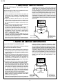
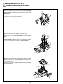
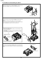
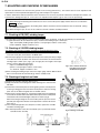
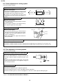
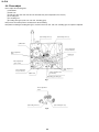
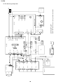
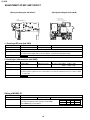
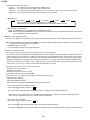
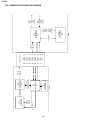
· Remove the screw ((x) LX-HZ0050TAFN), screw ((p) LXHZ0063TAFN) and screw ((a) XiPSN17P02000), disconnect
the FPC (1) and remove the camera top cover.
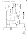
· Remove the screw ((b) XiPSN17P03000) from the camera
unit, disconnect the FPC (2) and remove the camera unit.
· Remove the screw ((b) XiPSN17P03000), disconnect the
connector and FPC (3) and remove the VF.
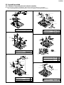
5.
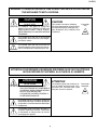
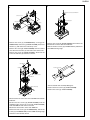
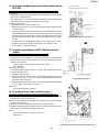
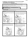
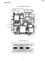
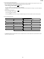
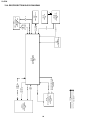
· Remove the screw ((b) XiPSN17P03000) and remove the
Mechanism reversion detection PWB unit.
· Remove the three screws ((u) LX-BZ0221TAFC) and remove
the PWB mounting angle.
7.
x
Sub PWB unit
b
Radiating angle
b
LCD tilt unit assembly
b
b
Terminal cabinet
b
Main PWB unit
a
b
x
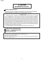
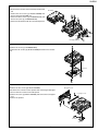
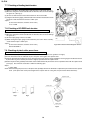
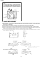
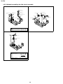
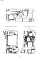
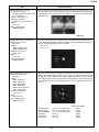
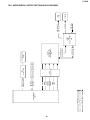
· Turn the LCD tilt unit assembly 90 degrees.
· Remove the three screws ((b) XiPSN17P03000).
· Remove the screw ((a) XiPSN17P02000).
PWB mounting angle
x
Connector
Tilt FPC
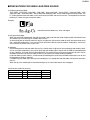
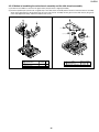
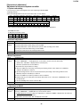
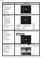
· Disconnect the two connectors of the sub PWB unit and main
PWB unit.
· Remove the two screws ((b) XiPSN17P03000) from the
radiating angle, remove the screw ((b) XiPSN17P03000)
from the PWB unit and remove each unit.
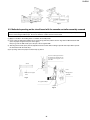
· Disconnect the two FFCs of the main PWB unit.
· Remove the two screws ((x) LX-HZ0050TAFN), remove the
screw ((x) LX-HZ0050TAFN) from the PWB mounting angle
and remove the terminal cabinet.
9