1
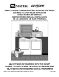
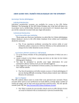
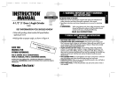
HIGH-EFFICIENCY WASHER INSTALLATION INSTRUCTIONS
MACHINE À LAVER HAUTE EFFICACITÉ
GUIDE DE MISE EN SERVICE
INSTRUCCIONES PARA LA INSTALACIÓN
DE LA LAVADORA DE ALTA EFICIENCIA
LEAVE THESE INSTRUCTIONS WITH THE OWNER
LAISSER CE GUIDE DE MISE EN SERVICE AU PROPRIÉTAIRE
DEJAR ESTAS INSTRUCCIONES CON EL PROPIETARIO
(7/28/04 Revision)
(0623/04
2201459
READ THIS BEFORE YOU START…
ELECTRICAL
Tools needed for installation:
Refer to serial plate for specific
electrical requirements. For
more detailed information refer
to section on Electrical
Requirements.
• Multi wrench
• Utility knife
• Channel lock
• Level
WATER
Washer needs two standard
3/4 inch water supply faucets
with a pressure between
20–120 pounds per square inch.
For more detailed information
refer to section on Water
Requirements.
PARTS supplied for installation:
Cable tie to secure drain hose to standpipe, inlet hose or laundry tub
CABINET DIMENSIONS
WASHER DIMENSIONS
INCH (CM)
A. Height – Overall*
B. Depth to Front of Control Dial
C. Width
D. Depth – With Washer Door Open 90°
E. Depth
33.25” (84.5)
26” (66.1)
23.5” (59.7)
41.25” (104.3)
24” (60.9)
E
Note:
The height of the washer from top to floor is 33 1\4" this includes the leveling leg screwed all the way in. The customer
can unscrew the leg out an additional 7\8" for a total overall height of 34 1\8".
2
BASIC LOCATION REQUIREMENTS:
ELECTRICAL
•
•
•
120 Volt 60 Hz 15 AMP Fuse or Circuit Breaker
Individual branch circuit serving only the washer is recommended.
The washer is equipped with a power cord.
NEVER USE AN EXTENSION CORD.
GROUNDING
ELECTRICAL GROUND IS REQUIRED ON THIS APPLIANCE.
Appliance is equipped with a power cord having a 3-prong grounding plug for use in a properly installed and
grounded outlet.
! WARNING
•
Improper connection of the equipment-grounding conductor can result in a risk of electrical
shock. Check with a qualified electrician or serviceman if you are in doubt as to whether
the appliance is properly grounded. Do not modify the plug provided with the appliance – if
it will not fit the outlet, have a proper outlet installed by a qualified electrician.
IMPORTANT SAFETY PRECAUTIONS
•
To prevent unnecessary risk of fire, electrical shock or personal injury, all wiring and
grounding must be done in accordance with the National Electrical Code ANSI/FNPA, No.
70-Latest Revision and local codes and ordinances. It is the personal responsibility and obligation of the appliance owner to provide adequate electrical service for this appliance.
ADDITIONAL GROUNDING CONNECTIONS
A grounding kit (Part No. 12001875) is available. It contains the ground wire,
clamp, ground screw and washer. Connect the ground wire to back of unit
with the cabinet ground screw and washer. Secure the other end of ground
wire to a grounded COLD metal water pipe.
NEVER CONNECT GROUND WIRE TO PLASTIC PLUMBING LINES, GAS LINES OR HOT WATER
PIPES.
WATER
To correctly fill the washer in the proper amount of time, Water pressure of 20 to 120 p.s.i. is required.
Water pressure less than 20 psi may cause a failure in the water valve and may not allow the water
valve to shut off completely. Or may extend the fill time beyond what the washer controls will normally
allow and result in the washer turning off. A time limit is built into the controls in the event of an
internal hose becoming loose and avoids a flooded home.
The water valve Hot and Cold water faucets must be within 4 feet of the back of the washer for inlet
hoses provided with the washer. NOTE: Accessory inlet hoses are available in various lengths up to
10 feet for faucets more than 4 feet from the back of the washer.
3
To Avoid The Possibility Of Water Damage:
•
•
Have Water Faucets Easily Accessible
Turn Off Faucets When Washer Is Not In Use.
DRAIN FACILITY
Recommended height of the standpipe is 18”. The drain hose must be routed through the drain hose clip to
the standpipe. Standpipe must be large enough to accept the outside diameter of the drain hose. The drain
hose is attached at the factory.
FLOORING
For best performance the washer must be installed on a solidly constructed floor. Wood floors may need to
be reinforced to minimize vibration and/or unbalanced load situations. Carpeting and soft tile surfaces are
contributing factors in vibration and/or tendency for a washer to move slightly during the spin cycle. Never
install the washer on a platform or weakly supported structure.
LOCATION CONSIDERATIONS
It is recommended the washer never be installed in areas where water may freeze since the washer will
always maintain some water in the water valve, pump and hose areas. This can cause damage to belts,
pump, hoses and other components. Operating temperature should be above 60°F.
ALCOVE OR CLOSET INSTALLATION
MINIMUM CLEARANCES FOR CLOSET AND ALCOVE INSTALLATIONS:
0 mm
Sides – 0 in / 0 mm Rear – 0
1 in / 25
0 mm Closet Front – 0 in / 0 mm
Top – 0
2 in / 51
The closet front must have a total unobstructed air opening of 72 in2. / 465 cm2 minimum, if both washer and
dryer are installed together. A louvered door with equivalent air opening is acceptable. Washer alone does
not require specific air opening.
UNDERCOUNTER INSTALLATION
MINIMUM CLEARANCES FOR UNDERCOUNTER INSTALLATIONS:
Sides – 0 in / 0 mm Rear – 0 in / 0 mm
Top – 0 in / 0 mm Front – 0 in / 0 mm
33 1/4" - 34 1/8"
26” m
in.
”
23 1/2
4
STACKING KIT INSTALLATION
A special stacking kit is available to allow stacking of the dryer on top of
the washer. This is available as an accessory item and is available
through your selling dealer. The model number for the accessory kit is
MAL2424AXX
ADDITIONAL INFORMATION
50-HERTZ OPERATION
This Maytag appliance is manufactured for operation on 60 Hz AC approved electrical service. This model is
not designed for use on 50 Hz AC electrical services and conversion of the product from 60 to 50 Hz
operations is not recommended. For additional information on 50 Hz products, write:
MAYTAG
MAYTAGINTERNATIONAL,
INTERNATIONAL, INC.
INC.
1475
Woodfield
Road
8700 East
BRYN
MAWR AVE.
Schaumburg,
Illinois 60173
CHICAGO, ILLINOIS
60631
Phone:
Phone: 847-273-3100
773-714-0100
FOR TECHNICAL ASSISTANCE, REPLACEMENT PARTS AND ACCESSORIES
For technical assistance or if your washer requires replacement parts or accessories, contact Maytag
Customer Service, toll-free 1-888-4-Maytag for information on the nearest authorized Maytag Parts
Distributor.
Proper installation is the responsibility of the owner; Service Calls Performed As A Result Of Improper Set-up,
Adjustment And/Or Connection Are The Responsibility Of The Installer.
UNPACKING THE WASHING MACHINE
Unpack your washing machine and inspect it for shipping damage and have you
have received all of the items shown on page 2. If the washing machine was
damaged during shipping or you do not have all of the items, contact your
Maytag dealer immediately.
5
IMPORTANT TO INSTALLER
Please Read The Following Instructions Carefully Before Installing The
Washing Machine.
These Instructions Should Be Retained For Future Reference.
Remove The Door From All Discarded Appliances To Avoid The Danger Of
A Child Suffocating.
STEP 1
PREPARE WASHER
Removing The Shipping Bolts
Before using the washing machine, you must remove the five shipping bolts
from the back of the unit.
1. Loosen all bolts with the supplied wrench before
removing them.
2. Slide the bolt and spacer up and remove the bolt
with spacer through the hole in the rear wall of the
washer. Repeat for each bolt.
3. Fill the holes with the supplied plastic covers.
4. Keep the shipping bolts and spacers for future use.
STEP 2
INSTALLING THE WASHING MACHINE
Selecting a location
Before you install the washing machine, select a location with the following characteristics:
• A hard, level surface (if the surface is uneven, see “Adjusting the leveling feet,”
below)
• Locate away from direct sunlight.
• Adequate ventilation
• Room temperature that will not fall below 0
°C or 0°C.
32°F
• Away from sources of heat such as coal or gas
• Make sure that the washing machine does not stand on its power cord.
• Carpeting must not obstruct ventilation openings when the washing machine is
installed on a carpeted floor.
6
STEP 3
INSTALL THE WASHER
(NOTE: Under the counter installation do not require removal of the work top. Proceed with
the following instructions.)
1. Place the drain hose in the drain facility. Be sure an airtight
1.
connection is NOT made between the drain hose and the
standpipe. Standpipe must be at least 18” high.
NOTE: If drain standpipe is in excess of 5 feet above floor level, a
(Part #12001660)
#12002482) will need to be installed.
drain hose extension kit (Part
If drain standpipe is in excess of 10 feet above floor level, a pump
accessory kit (Part #12001674) may need to be installed.
NOTE: Caution must always be exercised to avoid collapsing or
damaging the drain hose. For best performance the drain hose
should not be restricted in any way, through elbows, couplings or
excessive lengths.
For installations where the drain hose cannot be conveniently
elevated to at least 18”, the drain hose must be supported.
2. Check the inlet hose to ensure a screen strainer and washer is
the inlet hose to ensure a washer is inside of each fill
2. Check
inside of each fill hose. Thread the inlet hoses with the screen
hose. Thread the inlet hoses to the HOT and COLD faucet conwasher to the HOT and COLD faucet connections. The dome on
nections. On the other end of the hose, check for one rubber
the screen strainer must point towards the faucet. On the other
washer per hose and install each fill hose to the water valve.
end of the hose, check for one rubber washer per hose and install
Make sure the hose marked “HOT” is attached to the HOT
each fill hose to the water valve. Make sure the hose marked
faucet. Tighten by hand until snug and then 2/3 of a turn with
“HOT” is attached to the HOT faucet. Tighten by hand until snug
pliers. DO NOT OVERTIGHTEN.
and then 2/3 of a turn with pliers. DO NOT OVERTIGHTEN.
3. Turn on “HOT” and “COLD” water supply and check all
connections at the water valve and the faucet for leaks. NOTE:
Accessory inlet hoses are available in various lengths up to 10
feet.
4. Plug power cord into a grounded 120 volt 60 Hz approved
electrical service protected by a 15-amp fuse or comparable circuit
breaker. This washer is grounded through the third prong of the
power cord when plugged into a three prong grounded receptacle.
5. Slide washer into position.
6. Level washer by turning the leveling legs in or out as necessary
by hand. When the washer is level, tighten the leveling leg lock
nuts up against the base of the washer using the wrench
supplied with the washer. NOTE: The washer must be leveled
on all 4 sides. A carpenter’s level should be used on all 4
corners of the washer. It’s a good idea after the first dozen
washes to recheck the levelness of the washer.
7
96” MAX.
18” MIN.
96” MAX.
18” MIN.
If installing under a counter:
Carefully move the washer in front of it’s final location. Adjust the rear leveling legs to the
required height and level the washer across the back of the washer. Tighten the leveling
locking nuts up against the bottom of the washer base with the wrench. Adjust the front
leveling legs to level the washer in respect to the rear leveling legs. Gently lift up on the front
of the washer and slide back into the recess.
With the washer in its final position, place a level along the top edge of the washer. (no rocking
of the washer should exist). Adjust the front leveling legs up or down to ensure the washer is
resting solid. Turn the lock nuts on each leg up towards the base of the washer and snug with
a wrench.
NOTE: Keep the leg extension at a minimum to prevent excessive vibration.
The farther out the legs are extended the more the washer will vibrate and
possibly walk.
FINAL INSTALLATION CHECKLIST
o
Instruction and Installation Kit have been removed from tub.
o
Shipping bolts and spacers have been removed.
o
Washer is plugged into electrical outlet and is properly grounded.
o
Water hoses are connected to the faucets with inlet screens and washers.
o
Water is turned on and checked for leaks at faucet and water valve connections on back of washer.
o
Drain hose is properly located into drain facility and is not collapsed or damaged.
o
Washer has been properly leveled. All legs should be firmly on the floor and leveling leg lock nuts tightened
up against the bottom of the washer base frame.
o
Washer fills properly on all temperature selections.
o
Test for proper operation by running the washer through a complete cycle.
COLD WEATHER STORAGE
The following precautions should be taken if a washer is to be stored, after use, where it would be subject to
freezing conditions.
1. Turn off the water supply, then remove the inlet hoses from the facets.
2. Place the end of the inlet hoses into a bucket or container. Select a fill cycle and energize the water valve by
selecting a warm water setting. A few seconds of fill is sufficient to empty the inlet hoses.
3. Disconnect from electrical supply.
4. Lower the drain hose to floor level and tilt washer backwards to remove water from the drain hose and
pump.
8