1
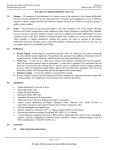
Hydraulic Linear Drive
Installation instructions
E12207 Type 2 (12 V)
E12208 Type 2 (24 V)
M81202 Type 3 (12 V)
M81203 Type 3 (24 V)
Trademarks and registered trademarks
Autohelm, hsb2, RayTech Navigator, RayTalk, Sail Pilot, SeaTalk, SeaTalkNG, SeaTalkHS and Sportpilot are registered trademarks of
Raymarine UK Limited. Seahawk, Smartpilot, Pathfinder and Raymarine are registered trademarks of Raymarine Holdings Limited.
All other product names are trademarks or registered trademarks of their respective owners.
Fair Use Statement
You may print no more than three copies of this manual for your own use. You may not make any further copies or distribute or use the
manual in any other way including without limitation exploiting the manual commercially or giving or selling copies to third parties.
Copyright ©2010 Raymarine UK Ltd. All rights reserved.
ENGLISH
Document number: 81177-5
Date: 05-2010
Contents
Chapter 1 Important information............................. 7
Chapter 3 Mounting.................................................. 21
Handbook information ..................................................... 7
Certified Installation ........................................................ 7
EMC conformance .......................................................... 8
Technical accuracy ......................................................... 9
Product disposal ............................................................. 9
EMC installation guidelines ............................................. 9
Connections to other equipment ...................................... 9
Warranty registration....................................................... 10
Installation prerequisites.................................................. 10
3.1 Mounting checklist..................................................... 22
3.2 Hydraulic ram alignment ............................................ 22
3.3 Hydraulic ram mounting............................................. 24
3.4 Steering system connection ....................................... 24
3.5 Hydraulic pump mounting .......................................... 26
3.6 Reservoir mounting ................................................... 27
3.7 Filling the reservoir.................................................... 27
Chapter 2 Planning................................................... 11
2.1 Installation checklist .................................................. 12
2.2 Drive types ............................................................... 12
2.3 Reservoir.................................................................. 13
2.4 Product overview ...................................................... 13
2.5 Typical system .......................................................... 14
2.6 Parts supplied........................................................... 15
2.7 Parts required ........................................................... 16
2.8 Location and mounting requirements .......................... 16
2.9 Product differences ................................................... 18
2.10 Dimensions............................................................. 18
2.11 Dimensions ............................................................. 19
Chapter 4 Cables and connections......................... 29
4.1 General cabling guidance .......................................... 30
4.2 Clutch connection ..................................................... 31
4.3 Course computer connection ..................................... 32
4.4 Post-installation check............................................... 34
Chapter 5 Maintenance and troubleshooting .............................................................................. 35
5.1 Maintenance checks.................................................. 36
5.2 Bleeding the system .................................................. 36
5.3 Troubleshooting ........................................................ 37
5.4 Raymarine technical support...................................... 38
Appendix A Technical specification ....................... 39
5
6
Hydraulic Linear Drive Installation instructions
Chapter 1: Important information
Certified Installation
Handbook information
Raymarine recommends certified installation by a Raymarine
approved installer. A certified installation qualifies for enhanced
product warranty benefits. Contact your Raymarine dealer for
further details, and refer to the separate warranty document packed
with your product.
This handbook contains important information regarding the
Hydraulic Linear Drives.
The handbook is for use with the following models:
Warning: Product installation and
operation
Part number
Type
Voltage
E12207 (replaces
M81200)
Type 2
12 V
E12208 (replaces
M81201)
Type 2
24 V
This product must be installed and operated in
accordance with the instructions provided. Failure to
do so could result in personal injury, damage to your
boat and/or poor product performance.
M81202
Type 3
12 V
Warning: Switch off power supply
M81203
Type 3
24 V
Ensure the boat’s power supply is switched OFF
before starting to install this product. Do NOT connect
or disconnect equipment with the power switched on,
unless instructed in this document.
Additional handbooks
The following handbooks provide additional information relating to
the operation of the Hydraulic Linear Drive, and compatible course
computers.
Description
Part number
SPX System Installation guide
87072
SPX System Commissioning
Instructions
81287
SeaTalkng Reference Manual
81300
Important information
Warning: Entrapment hazard
This product features moving parts that provide a
potential entrapment hazard. Keep clear of moving
parts at all times.
Warning: Do NOT flash test
Do NOT perform an electrical flash test on this product.
7
Warning: Hydraulic fluid
Caution: Ensure cleanliness
Important safety information:
Absolute cleanliness is essential when working with
hydraulic systems. Even the smallest dirt particle
could prevent the steering system check valves from
working correctly.
• Eyes — Fluid is unlikely to cause eye irritation but
the use of eye protection is advised. If fluid comes
into contact with eyes, rinse with copious amounts
of water.
• Skin — Fluid is unlikely to cause immediate
irritation, but prolonged and repeated contact may
be harmful to the skin. The use of nitrile gloves is
recommended. If skin is exposed to fluid wash the
contaminated skin thoroughly with soap and water.
• Ingestion — Unlikely to cause adverse systemic
health effects. If ingested DO NOT INDUCE
VOMITING, and seek medical attention.
• Inhalation — Remove the affected person to fresh
air. If recovery is not rapid obtain medical attention.
Warning: Ensure safe navigation
This product is intended only as an aid to navigation
and must never be used in preference to sound
navigational judgment. Only official government
charts and notices to mariners contain all the current
information needed for safe navigation, and the
captain is responsible for their prudent use. It is the
user’s responsibility to use official government charts,
notices to mariners, caution and proper navigational
skill when operating this or any other Raymarine
product.
Caution: Structural strength
During operation the Hydraulic Linear Drive produces
a considerable amount of force. You MUST mount the
Hydraulic ram to a very solid structure (for example,
a substantial frame member of your vessel). Both the
structure and the tiller arm or rudder quadrant MUST
be capable of withstanding the peak levels of thrust
stated in the Technical Specification in this document.
In some cases it may be necessary to build a specially
strengthened frame to mount the drive unit. Consult
the steering gear manufacturer if you have any doubt
about the strength of the tiller arm or rudder quadrant.
Caution: Avoid damage to hydraulic
ram
Any damage to the hydraulic ram will damage the
seals and allow air into the unit, reducing performance
and potentially causing oil leaks.
EMC conformance
Raymarine equipment and accessories conform to the appropriate
Electromagnetic Compatibility (EMC) regulations for use in the
recreational marine environment.
8
Hydraulic Linear Drive Installation instructions
Correct installation is required to ensure that EMC performance is
not compromised.
For optimum EMC performance we recommend that wherever
possible:
• Raymarine equipment and cables connected to it are:
Technical accuracy
To the best of our knowledge, the information in this document was
correct at the time it was produced. However, Raymarine cannot
accept liability for any inaccuracies or omissions it may contain. In
addition, our policy of continuous product improvement may change
specifications without notice. As a result, Raymarine cannot accept
liability for any differences between the product and this document.
– At least 1 m (3 ft) from any equipment transmitting or cables
carrying radio signals e.g. VHF radios, cables and antennas.
In the case of SSB radios, the distance should be increased
to 7 ft (2 m).
– More than 2 m (7 ft) from the path of a radar beam. A radar
beam can normally be assumed to spread 20 degrees above
and below the radiating element.
Product disposal
• The product is supplied from a separate battery from that used
for engine start. This is important to prevent erratic behavior
and data loss which can occur if the engine start does not have
a separate battery.
Dispose of this product in accordance with the WEEE Directive.
• Raymarine specified cables are used.
• Cables are not cut or extended, unless doing so is detailed in
the installation manual.
The Waste Electrical and Electronic Equipment (WEEE)
Directive requires the recycling of waste electrical and electronic
equipment. Whilst the WEEE Directive does not apply to some
Raymarine products, we support its policy and ask you to be aware
of how to dispose of this product.
EMC installation guidelines
Raymarine equipment and accessories conform to the appropriate
Electromagnetic Compatibility (EMC) regulations, to minimize
electromagnetic interference between equipment and minimize the
effect such interference could have on the performance of your
system
Correct installation is required to ensure that EMC performance is
not compromised.
Important information
Note: Where constraints on the installation prevent any of
the above recommendations, always ensure the maximum
possible separation between different items of electrical
equipment, to provide the best conditions for EMC performance
throughout the installation
Connections to other equipment
Requirement for ferrites on non-Raymarine cables
If your Raymarine equipment is to be connected to other equipment
using a cable not supplied by Raymarine, a suppression ferrite
MUST always be attached to the cable near the Raymarine unit.
9
Warranty registration
To register your Hydraulic Linear Drive ownership, please take a few
minutes to fill out the warranty registration card found in the box, or
visit www.raymarine.com and register on-line.
It is important that you register your product to receive full warranty
benefits. Your unit package includes a bar code label indicating the
serial number of the unit. You should stick this label to the warranty
registration card.
Installation prerequisites
Before installing this product you must adhere to the installation
prerequisites.
The hydraulic ram drives the rudder directly from the tiller arm or
rudder quadrant. Before installing this drive unit, check that the
vessel’s steering system can be backdriven from the rudder.
10
Hydraulic Linear Drive Installation instructions
Chapter 2: Planning
Chapter contents
•
2.1 Installation checklist on page 12
•
2.2 Drive types on page 12
•
2.3 Reservoir on page 13
•
2.4 Product overview on page 13
•
2.5 Typical system on page 14
•
2.6 Parts supplied on page 15
•
2.7 Parts required on page 16
•
2.8 Location and mounting requirements on page 16
•
2.9 Product differences on page 18
•
2.10 Dimensions on page 18
•
2.11 Dimensions on page 19
Planning
11
2.1 Installation checklist
2.2 Drive types
Installation includes the following activities:
There are 2 drive types. Each drive type has 2 variants (one for
12 V systems, one for 24 V systems).
Installation Task
1
Plan your installation.
Although the core functionality of each drive type is essentially the
same, the form factor of some of the components differs as follows:
2
Obtain all required equipment and tools.
Hydraulic ram
3
Mount the system components.
Type 2 drive:
4
Route all cables.
5
Drill cable and mounting holes.
6
Make all connections to equipment.
7
Secure all equipment in place.
8
Complete the post-installation check.
D11864-1
Type 3 drive:
D11865-1
Note: The drawings included in this handbook are for illustration
purposes only. The exact shape of your system components may
differ from those shown.
12
Hydraulic Linear Drive Installation instructions
2.3 Reservoir
2.4 Product overview
The Hydraulic Linear Drive is intended to operate a vessel’s steering
mechanism as part of a Raymarine autopilot system.
The Hydraulic Linear Drive is designed for vessels with existing
mechanical steering systems, NOT hydraulic steering systems. It
is mounted below decks and moves the rudder directly by pushing
the tiller arm or rudder quadrant.
The Hydraulic Linear Drive provides a totally isolated autopilot
steering system consisting of:
1
2
3
2
4
1
4
5
3
5
11
9
D11866-1
1. Transit screw — must be removed from the cap before use.
7
8
6
10
D11851-1
2. Screw cap — seal must be removed from cap before use.
3. Fill level — reservoir must be filled between the minimum and
maximum levels.
4. Mounting hole — for securing the reservoir to a suitable part
of your vessel.
5. Tap — controls the flow of hydraulic fluid to the pump.
1. Hydraulic fluid reservoir — supplies hydraulic fluid to the
system.
2. Reservoir pipe — transports the hydraulic fluid from the
reservoir to the pump.
3. Ram pipe — low-pressure line between the pump and the
hydraulic ram.
4. Reversing hydraulic pump — powers the hydraulic arm.
5. Motor cables — for connecting the pump to a course computer.
6. Rod end — connects the hydraulic ram to your vessel’s tiller or
rudder quadrant.
Planning
13
7. Push rod — extends out of the hydraulic ram casing to control
the tiller arm or rudder quadrant.
8. Hydraulic ram — a self-contained autopilot steering cylinder
with a load-limiting system and built-in clutch.
9. Pump pipes — high-pressure lines between the pump and the
hydraulic ram.
2.5 Typical system
The drive components connect to a course computer as part of an
autopilot system.
The following diagram illustrates a typical SPX-30 autopilot system:
1
10. Clutch cable — for connecting the hydraulic ram’s clutch to
the course computer clutch connections. The clutch allows
friction-free steering when the autopilot is not in use.
SMARTPILOT
2
11. Mounting foot — for mounting the hydraulic ram to a suitable
part of your vessel.
Rudder reference option
The course computer is supplied with a rudder reference sensor,
which provides enhanced performance for autopilot systems.
4
3
D11853-1
1. Autopilot controller.
2. SPX course computer.
3. Drive unit.
D11894-1
4. Fluxgate compass.
For information on installing and connecting the rudder reference
option refer to the instructions that accompany the course computer.
14
Hydraulic Linear Drive Installation instructions
2.6 Parts supplied
• Bolts (quantity: 4)
• Washers (quantity: 4).
• Lock nuts (quantity: 4).
4. Pump mounting screw pack, consisting of:
• Bolts (quantity: 2)
1
• Washers (quantity: 2).
• Lock nuts (quantity: 2).
5. Installation instructions.
6. Hydraulic fluid transit container.
2
3
4
5
6
D11854-1
03
1. Hydraulic Linear Drive components, consisting of:
• Hydraulic fluid reservoir.
• Pump.
• Hydraulic ram.
2. Tiller pin assembly, consisting of:
• Tiller pin.
• R-clip.
• Lock nut.
• Washer (quantity: 2).
3. Hydraulic ram mounting screw pack, consisting of:
Planning
15
2.7 Parts required
2.8 Location and mounting requirements
Additional parts required, NOT supplied with the product.
Hydraulic ram
Location and mounting requirements:
The following additional parts are required for the installation of the
Hydraulic Linear Drive:
• Suitable bolts and associated nuts and washers for securing the
reservoir to a suitable part of your vessel. Quantity required: 2.
• Suitable bolts and associated nuts and washers for securing the
pump to a suitable part of your vessel. Quantity required: 2.
• Suitable cable and electrical connectors for connecting and
extending the motor and clutch cables.
• MUST be mounted on a very solid structure (for example, a
substantial frame member of your vessel). The drive produces a
considerable amount of force, so you MUST ensure that both the
structure and your tiller arm or rudder quadrant can cope with the
peak levels of thrust stated in the Technical Specification in this
document. In some cases it may be necessary to build a specially
strengthened frame to mount the drive unit. Consult the steering
gear manufacturer if you have any doubt about the strength of the
tiller arm or rudder quadrant.
• The Type 2 drive may be mounted horizontally or vertically.
• The Type 3 drive MUST be mounted horizontally with its mounting
foot on a horizontal surface. The swivel joint does NOT have
sufficient movement to position the foot vertically.
• The hydraulic ram must NOT foul any part of the vessel’s structure
or quadrant throughout its entire range of movement.
• MUST be mounted in a location allowing sufficient clearance for
the mounting pin to be removed if required.
• MUST be mounted with sufficient clearance at the rear of the ram
unit for the hydraulic pipes. You must allow at least 17 cm (6.7 in)
clearance at the rear of the unit for the extruding pipes.
• MUST be fitted in a dry area, free of bilge water (the ram is NOT
waterproof).
• MUST be accessible for future servicing.
• The supplied M8 bolts and washers are suitable for mounting
the hydraulic ram to a surface between 1.2 cm (0.47 in) and 2.4
cm (0.94 in) thick. Larger bolts and washers are required for
a thicker surface.
The following diagrams illustrate the correct drive orientation,
showing a view from above with the arrow indicating the aft direction:
16
Hydraulic Linear Drive Installation instructions
Type 2:
Hydraulic pump
Location and mounting requirements:
• MUST be mounted on a solid structure to avoid vibration that
could damage the hydraulic pipes.
• MUST be mounted on a dry horizontal surface, clear of spray
water and possible immersion.
• Excessive temperature, vibration and fumes in the atmosphere
can drastically reduce motor brush life.
• MUST be mounted level to or above the hydraulic ram, to prevent
air from collecting in the ram.
• MUST be accessible for future servicing.
Reservoir
Location and mounting requirements:
• MUST be mounted vertically, ideally to a bulkhead.
D11899-1
Type 3:
• MUST be mounted at least 150 mm (6 in) ABOVE the hydraulic
pump and hydraulic ram, to ensure a good supply of fluid to the
system.
• MUST be accessible for hydraulic fluid top-ups and refills.
• Raymarine recommends the use of M8 bolts and suitable nuts
and washers to secure the reservoir to the vessel.
Pipes
The pipes transport fluid and pressure around the Hydraulic Linear
Drive system. The system is supplied pre-plumbed, pre-filled, and
pre-bled, with just the reservoir empty. However you must observe
the following when handling and positioning the pipes:
• Do NOT allow acute bends in the pipes. The minimum bend
radius for the pipes is 7.6 cm (3 in).
D11855-1
• Pipes must NOT touch any part of the vessel.
Planning
• Ensure there are no kinks in the pipes.
• Ensure pipes are not cut or chaffed.
17
2.9 Product differences
2.10 Dimensions
Factors to consider when replacing an existing Type 2 drive
(M81200, M81201) with a new Type 2 drive (E12207, E12208).
Type 2 drive
• The existing Type 2 hydraulic ram (M81200, M81201) has a 5
degree tolerance of movement in the vertical plane. The new Type
2 hydraulic ram (E12207, E12208) has a 10 degree tolerance.
386.5 mm (15.22 in)
• The hydraulic fluid reservoir supplied with the new drive (E12207,
E12208) is a different size and shape.
101.5 mm (4 in)
• The new drive (E12207, E12208) can be mounted horizontally
or vertically.
147.75 mm (5.82 in)
• For the existing Type 2 drive (M81200, M81201) the pipes that
transported the hydraulic fluid to the ram unit were connected to
the top of the unit. For the NEW Type 2 drive (E12207, E12208),
the pipes connect to the rear of the unit. You must allow at least
17 cm (6.7 in) clearance at the rear of the unit for the extruding
pipes. The minimum bend radius for the pipes is 7.6 cm (3 in).
1
108.8 mm
(4.28 in)
573.5 mm (22.58 in)
116.0 mm (4.57 in)
There are a number of important differences between the 2 drives:
D11868-1
1. Hydraulic ram at mid stroke position.
18
Hydraulic Linear Drive Installation instructions
2.11 Dimensions
Type 3 drive
690 mm (27.15 in)
Reservoir dimensions.
1
457 mm (18 in)
9.5 mm
(0.37 in)
D11856-1
1. Hydraulic ram at mid stroke position.
55.3 mm
(2.17 in)
101.6 mm (4 in)
152 mm (6 in)
80 mm
(3.15 in)
148.7 mm (5.85 in)
D11901-1
Planning
19
20
Hydraulic Linear Drive Installation instructions
Chapter 3: Mounting
Chapter contents
•
3.1 Mounting checklist on page 22
•
3.2 Hydraulic ram alignment on page 22
•
3.3 Hydraulic ram mounting on page 24
•
3.4 Steering system connection on page 24
•
3.5 Hydraulic pump mounting on page 26
•
3.6 Reservoir mounting on page 27
•
3.7 Filling the reservoir on page 27
Mounting
21
3.1 Mounting checklist
3.2 Hydraulic ram alignment
Mounting the Hydraulic Linear Drive system involves the following
tasks:
When mounting the hydraulic ram ensure it is correctly aligned.
Mounting Task
1
Ensure you have read and understood the 2.8 Location and mounting
requirements.
2
Align the hydraulic ram.
3
Secure the hydraulic ram to your vessel.
4
Connect the hydraulic ram to the vessel’s steering system.
5
Perform a steering check to ensure the hydraulic ram is mounted
correctly.
6
Mount the hydraulic pump.
7
Mount the reservoir.
8
Fill the reservoir with hydraulic fluid.
Hydraulic ram
• The hydraulic ram must be at right angles to the mounting surface.
• The hydraulic ram must be in the mid stroke position and at right
angles to the tiller arm when the rudder is at midships.
The following diagram illustrates correct alignment of the hydraulic
ram. The hydraulic ram in the top half of the diagram shows the
view from astern. The bottom half of the diagram shows the view
from above. The grey arrow indicates the aft direction.
1
90º
90º
2
D11857-1
1. Hydraulic ram at the mid stroke position.
2. Tiller arm radius, as follows:
• Type 2: 180 mm (7.1 in).
• Type 3: 267 mm (10.5 in).
22
Hydraulic Linear Drive Installation instructions
Push rod and tiller arm
The push rod must be accurately aligned with the tiller arm plane
of rotation. The ball end fitting only allows the following degrees of
misalignment between the push rod and tiller arm plane of rotation:
Note: Accurate angular alignment of the hydraulic ram is
extremely important. You must NOT exceed the specified degree
alignment limits under any circumstances.
• Type 2 drive: 10 degrees.
• Type 3 drive: 5 degrees.
The following diagrams illustrate the degree limit for each type of
drive. The diagrams show a view from astern.
Type 2:
10º
10º
D11900-1
Type 3:
5º
5º
D11858-1
Mounting
23
3.3 Hydraulic ram mounting
3.4 Steering system connection
Mount the hydraulic ram as securely as possible to ensure it
performs reliably and remains correctly aligned.
The rod end of the hydraulic ram must be connected to the vessel’s
tiller arm or rudder quadrant.
Before connecting the hydraulic ram to the steering system, ensure
that your vessel’s tiller arm or rudder quadrant can cope with the
peak thrust stated in the Technical Specification.
Use one of the following methods to attach the push rod to the
rudder stock:
• Before mounting the hydraulic ram, refer to the guidance provided
in the 2.8 Location and mounting requirements section.
• Drill 4 holes for the mounting foot (each hole must be 8.8 mm
(0.34 in) diameter).
• Attach the mounting foot to the appropriate part of your vessel
using the supplied bolts, washers, and nuts.
• Tighten the bolts to 17 Nm (12.5 lb ft) torque.
• Independent tiller arm — this is the recommended method.
• Steering linkage tiller arm or rudder quadrant — in some
cases, you may be able to attach the push rod to the same
tiller arm or rudder quadrant used by the main steering linkage.
Consult the steering manufacturer before you modify the rudder
quadrant.
The following diagram illustrates the connection:
1
56 mm
26 mm
2
D11895-1
1. Tiller pin.
2. Tiller arm or rudder quadrant.
Attaching the rod end
Note: The supplied tiller pin is suitable for a quadrant thickness
of 12 mm (0.47 in) to 16 mm (0.63 in).
1. Attach the tiller pin to the tiller arm, as shown in the diagram
below:
24
Hydraulic Linear Drive Installation instructions
i.
Insert the tiller pin through the tiller arm hole so that the
flange remains above the arm.
ii. Ensure the tiller pin is a tight fit in the tiller arm. Raymarine
recommends the use of a suitable adhesive around the tiller
pin.
iii. Use the supplied lock washer and fully tighten the lock nut to
27 Nm (20 lb ft).
2. Attach the rod end to the tiller pin, as shown in the diagram
below:
i. Place the rod end on to the tiller pin.
ii. Secure with the supplied washer and R-clip.
7. Lock nut.
8. Tiller pin.
9. Hole diameter, as follows:
• Type 2: 12.2 mm (0.48 in).
• Type 3: 20 mm (0.78 in).
Note: It may be necessary to drill a hole in the tiller arm. The hole
must be of the diameter specified above.
Steering check
1
2
Once the hydraulic ram is mounted you must perform a steering
check to ensure the ram has been mounted correctly.
3
Turn your vessel’s steering wheel from hardover to hardover and
check the following:
4
5
6
• Angular movement of the ball end fitting is less than 10 degrees
for the Type 2 drive, or 5 degrees for the Type 3 drive. If this
limit is exceeded the drive will catch on the tiller arm or rudder
quadrant and the ball joint will bind.
7
8
• Ensure no part of the drive unit fouls your vessel’s structure when
the push rod moves in and out.
9
D11859-1
1. R-clip.
• Ensure that the total rudder movement is limited to +/- 35 degrees
by the steering system end stops, rather than the linear drive’s
end limits.
2. Washer.
3. Rod end.
4. Flange.
5. Tiller arm.
6. Lock washer.
Mounting
25
3.5 Hydraulic pump mounting
The hydraulic pump must be mounted in a suitable location to
ensure reliable performance.
• Before mounting the hydraulic pump, refer to the guidance
provided in the 2.8 Location and mounting requirements section.
2
1
• Drill 2 mounting holes.
• Secure the pump to the appropriate part of your vessel using
suitable stainless steel bolts, washers and lock nuts.
• Fully tighten the nuts to minimize vibration.
35º
35º
D11860-1
1. Steering system end stop: –35 degrees.
2. Steering system end stop: +35 degrees.
Caution: Total rudder movement
Ensure that the rudder movement is limited by the
steering end stops before the push rod reaches its
end stop. Failure to do this could damage the drive
and will invalidate the warranty.
26
Hydraulic Linear Drive Installation instructions
3.6 Reservoir mounting
3.7 Filling the reservoir
The reservoir must be mounted on a bulkhead as far above the
pump and hydraulic ram as possible.
The hydraulic fluid reservoir is supplied empty and must be filled to
the correct level with the supplied hydraulic fluid.
• Before mounting the reservoir, refer to the guidance provided in
the 2.8 Location and mounting requirements section.
Do NOT attempt to move or operate the hydraulic push rod before
completing the following steps:
1. The reservoir is fitted with a special cap featuring a breather
hole, which is sealed for transit purposes. Remove the transit
screw and seal from the cap to open the breather. Retain the
screw and seal for future use.
2. Fill the reservoir with the supplied hydraulic fluid to a level
between the minimum and maximum indicator lines.
3. Turn the tap to the “ON” position (tap should be pointing upward).
• Secure the reservoir to the appropriate part of your vessel, using
the mounting holes provided. Use suitable stainless steel bolts,
washers and lock nuts.
Mounting
27
28
Hydraulic Linear Drive Installation instructions
Chapter 4: Cables and connections
Chapter contents
•
4.1 General cabling guidance on page 30
•
4.2 Clutch connection on page 31
•
4.3 Course computer connection on page 32
•
4.4 Post-installation check on page 34
Cables and connections
29
4.1 General cabling guidance
Always route data cables as far away as possible from:
• other equipment and cables,
Cable types and length
• high current carrying ac and dc power lines,
It is important to use cables of the appropriate type and length
• Unless otherwise stated use only standard cables of the correct
type, supplied by Raymarine.
• Ensure that any non-Raymarine cables are of the correct quality
and gauge. For example, longer power cable runs may require
larger wire gauges to minimize voltage drop along the run.
• antennae.
Strain relief
Ensure adequate strain relief is provided. Protect connectors from
strain and ensure they will not pull out under extreme sea conditions.
Routing cables
Cable shielding
Cables must be routed correctly, to maximize performance and
prolong cable life.
Ensure that all data cables are properly shielded that the cable
shielding is intact (e.g. hasn’t been scraped off by being squeezed
through a tight area).
• Do NOT bend cables excessively. Wherever possible, ensure a
minimum bend radius of 100 mm.
Minimum bend
200 mm (8 in)
diameter
Minimum bend of cable
100 mm (4 in) radius
Warning: Ensure correct voltage
Do NOT connect a 24 V pump to a course computer
that only supports 12 V. For course computers that
support both 12 V and 24 V ensure that the correct
voltage is selected for the clutch terminal.
• Protect all cables from physical damage and exposure to heat.
Use trunking or conduit where possible. Do NOT run cables
through bilges or doorways, or close to moving or hot objects.
• Secure cables in place using tie-wraps or lacing twine. Coil any
extra cable and tie it out of the way.
• Where a cable passes through an exposed bulkhead or deckhead,
use a suitable watertight feed-through.
• Do NOT run cables near to engines or fluorescent lights.
30
Hydraulic Linear Drive Installation instructions
4.2 Clutch connection
1
The clutch (bypass valve) on the hydraulic ram unit must be
connected to the clutch terminals on the course computer, and
a suitable ground.
The clutch is used to bypass the hydraulic ram and operate the
steering system manually when there is a problem with the autopilot
system. The clutch is located at the rear of the hydraulic ram unit:
2
3
1
D11897-1
1. The item labelled “1” in the diagram above is the clutch.
To connect the clutch and ground cables you must remove the
clutch housing, using a suitable screwdriver. The clutch housing
contains the 3 terminals for the clutch and ground connections:
D11898-1
Item
Description
Suitable cable
1
Ground connection
Minimum 4 mm2 (12
AWG) copper cable.
2
Pin 1: POSITIVE
Minimum 1.5 mm2 (16
AWG) copper cable.
3
Pin 2: NEGATIVE
Minimum 1.5 mm2 (16
AWG) copper cable.
Once the cables have been connected re-assemble the clutch
housing and secure the screw using 0.5 Nm (0.37 lb ft) torque.
Cables and connections
31
4.3 Course computer connection
1
12V
RUDDER
24V
CLUTCH
2
3
P OWER, 15 AMP
The Hydraulic Linear Drive must be connected to an SPX-30 course
computer.
A
P OWER
4
5
1
7
Course
computer
Clutch
voltage
selector
switch
Adjust the voltage setting to match the
voltage rating specified on the Hydraulic
ram clutch.
Hydraulic
ram clutch
(+)
Clutch (+)
Connect the POSITIVE terminal of the
hydraulic ram’s clutch to the course
computer’s POSITIVE clutch terminal.
3
Hydraulic
ram clutch
(-)
Clutch (-)
Connect the NEGATIVE terminal of the
hydraulic ram’s clutch to the course
computer’s NEGATIVE clutch terminal.
4
Power
input (+)
Connect to POSITIVE terminal of power
supply (for example, via distribution
panel).
5
Power
input (-)
Connect to NEGATIVE terminal of power
supply (for example, via distribution
panel).
GROUND
8
6
Pump
motor (+)
Motor (+)
Connect the POSITIVE terminal of the
pump to the course computer’s MOTOR
A terminal.
7
Pump
motor (-)
Motor (-)
Connect the NEGATIVE terminal of the
pump to the course computer’s MOTOR
B terminal.
Ground
connection
Connect to a dedicated earthing plate in
contact with the water, or to the negative
pole of the battery.
9
D11896-1
8
9
32
Description
2
B
MOTOR
6
Item
Hydraulic
Linear
Drive
Hydraulic
ram ground
connection
Connect to the same earth as the course
computer.
Hydraulic Linear Drive Installation instructions
Note: For complete connection and installation instructions for
the course computer refer to the documentation that accompanies
the unit.
Cable extensions
You may need to extend the Hydraulic Linear Drive cables.
Use suitable electrical connectors or junction boxes to connect the
Hydraulic Linear Drive cables to the cable extensions.
Note: Do NOT untwist the pump cables or remove the
suppression ferrite.
• Clutch cable (from hydraulic ram to course computer clutch
connection) — use minimum 1.5 mm2 (16 AWG) copper cable.
• Motor cable (from Hydraulic pump to course computer motor
connection) — use the following table to determine the correct
cable gauge required:
Drive type
Cable length
Cable gauge
(AWG)
Cable gauge
(mm2)
Type 2 (12 V)
Up to 5 m (16 ft)
10
6
Up to 7 m (23 ft)
8
10
Up to 16 m (52 ft)
6
16
Up to 3 m (10 ft)
12
4
Up to 5 m (16 ft)
10
6
Up to 10 m (32 ft)
8
10
Up to 16 m (52 ft)
6
16
Up to 5 m (16 ft)
8
10
Up to 7 m (23 ft)
6
16
Up to 16 m (52 ft)
4
25
Up to 5 m (16 ft)
10
6
Up to 7 m (23 ft)
8
10
Up to 16 m (52 ft)
6
16
Type 2 (24 V)
Type 3 (12 V)
Type 3 (24 V)
Cables and connections
33
4.4 Post-installation check
Check the following points after installing the drive and connecting
the course computer:
Check
1
2
Ensure that the hydraulic ram’s mounting foot is well-secured to a
substantial part of the vessel.
Ensure that the hydraulic ram is correctly aligned:
• Mounting foot correctly orientated.
Check
9
Ensure that you’ve completed the hand-steering check (see Steering
check).
10
Ensure the course computer’s clutch switch is in the correct position
(refer to 4.3 Course computer connection).
Once you’ve completed the checks listed above you should perform
an autopilot steering check, to ensure that the autopilot control head,
course computer and drive unit are connected and communicating
correctly. Refer to the handbook that accompanies your course
computer.
• Drive mounted at right angles to tiller arm in a mid-stroke position
when rudder is in a midship position.
• Push rod accurately aligned with tiller arm plane of rotation
(deviation less than 10 degrees for Type 2 drives, or 5 degrees
for Type 3 drives).
3
Ensure that the hydraulic ram rod end is:
• Securely attached to the tiller arm or rudder quadrant.
• Attached at the recommended tiller arm radius for the vessel.
4
Ensure that the motor and clutch cables are correctly routed and
securely connected to the course computer.
5
Ensure that all hydraulic pipes are securely connected with no leaks.
6
Ensure that the reservoir is filled with hydraulic fluid to the correct level.
7
Ensure that the transit screw and seal have been removed from the
reservoir cap. Ensure that the cap is fitted securely to the reservoir.
8
Ensure that the reservoir tap is in the “ON” position.
34
Hydraulic Linear Drive Installation instructions
Chapter 5: Maintenance and troubleshooting
Chapter contents
•
5.1 Maintenance checks on page 36
•
5.2 Bleeding the system on page 36
•
5.3 Troubleshooting on page 37
•
5.4 Raymarine technical support on page 38
Maintenance and troubleshooting
35
5.1 Maintenance checks
Regular maintenance is required to ensure optimum operation.
Regular checks
• Check all mountings are secure, especially the hydraulic ram
mounting foot.
• Check the tiller pin is securely connected to rod end and tiller
arm or rudder quadrant.
• Check hydraulic ram alignment, as described in this handbook.
• Check all pipes for any signs of wear or damage.
• Check all cables and electrical connections for any signs of wear
or damage.
• Lubricate the rod end. Use only a good quality marine grease that
is compatible with nitrile seals.
Annual checks
• Check the hydraulic fluid level. The fluid in the reservoir should
be between the “minimum” and “maximum” levels indicated on
the reservoir. Top-up the fluid if necessary, using a suitable oil as
detailed in Appendix A Technical specification.
• Check the Hydraulic Linear Drive system for external oil loss,
which may indicate that the system needs bleeding.
36
5.2 Bleeding the system
Note: Raymarine recommends that bleeding the system is
undertaken by an authorized Raymarine dealer.
Before commencing ensure the oil and any storage containers are
clean and free of contamination.
1. Ensure the reservoir tap is in the “ON” position.
2. Push the hydraulic rod in so that it is fully retracted.
3. Fill the reservoir and slacken the pipes connected to the
hydraulic ram unit. Do NOT disconnect the pipes.
4. Re-tighten the pipes once the oil emerges from the fittings.
5. Run the pump in order to direct flow to the hydraulic cylinder
ports.
6. Energise the cylinder solenoid and slowly pull the hydraulic rod
out until it is fully extended. Observe the oil level in the reservoir
and top up if necessary, using the oil recommended in Appendix
A Technical specification .
The oil level will rise when the rod is retracted and may overflow.
7. Fully retract the rod, again observing the oil level in the reservoir
and topping up as needed. Repeat until no more air can be
seen to be rising into the reservoir and the pump takes over.
De-energise the solenoid.
8. To complete the bleeding, energise the cylinder solenoid again
and run the pump in both directions to extend and retract
the hydraulic rod. Note that the cylinder may need manually
assisting at first to purge any remaining air in the system.
9. Top up the reservoir if necessary to the level indicated.
Hydraulic Linear Drive Installation instructions
5.3 Troubleshooting
Potential problems with the Hydraulic Linear Drive system and possible causes and solutions are described here.
Problem
Possible causes
Possible solutions
Motor does not run.
The motor has no power supply.
Check all electrical connections.
The motor is not receiving instructions
from the course computer.
Check the connection between the autopilot control head and the course
computer, and between the course computer and the pump.
The motor brushes are worn.
Check motor brushes. If necessary contact your dealer for replacement
brushes.
The clutch in the hydraulic ram unit is not
working correctly.
Check for clutch operation.
Excessive air in the hydraulic ram unit.
Check for air in the hydraulic ram unit. External oil loss may indicate this.
The system may need bleeding.
Drive coupling.
Contact your dealer and ask them to check the motor drive coupling. The
dealer should ensure that the coupling is in place and aligned with the
motor drive tang.
Motor may be damaged or faulty.
Check the motor for damage.
Excessive air in the hydraulic ram unit.
Check for air in the hydraulic ram unit. External oil loss may indicate this.
The system may need bleeding.
Drive coupling.
Contact your dealer and ask them to check the motor drive coupling. The
dealer should ensure that the coupling is in place and aligned with the
motor drive tang.
Motor runs, but erratic or no hydraulic rod
movement.
Excessive pump noise.
Note: Under no circumstances dismantle the unit unless it is
certain that the fault is internal. Doing so will allow air into the
cylinder, requiring the unit to be bled.
Maintenance and troubleshooting
37
5.4 Raymarine technical support
Raymarine provides a comprehensive customer support service, on
the world wide web, through our worldwide dealer network and by
telephone help line. If you are unable to resolve a problem, please
use any of these facilities to obtain additional help.
Web support
Please visit the customer support area of our website at:
www.raymarine.com
This contains Frequently Asked Questions, servicing information,
e-mail access to the Raymarine Technical Support Department and
details of worldwide Raymarine agents.
Telephone support
In the USA call:
+1 603 881 5200 extension 2444
In the UK, Europe, the Middle East, or Far East call:
+44 (0)23 9271 4713
Product information
If you need to request service, please have the following information
to hand:
• Product name.
• Product identity.
• Serial number.
• Software application version.
You can obtain this product information using the menus within your
product.
38
Hydraulic Linear Drive Installation instructions
Appendix A Technical specification
Specification (at
nominal voltage)
Type 2
Type 3
Maximum vessel
displacement
22000 kg (48500 lb)
35000 kg (77000 lb)
Peak thrust
675 kg (1488 lb)
1000 kg (2200 lb)
Maximum stroke
254 mm (10 in)
300 mm (12 in)
Hardover to hardover
time (+/- 35 degrees, no
load)
10 seconds
12 seconds
Maximum rudder torque
1270 Nm (11300 lb in)
2565 Nm (23100 lb in)
Conformance (applies to
Type 2 and Type 3)
• EN60945:2002 (EMC)
– 2004/108/EC (EMC Directive)
• EN28846:1993 (Ignition Protection)
– 94/25/EC (RCD)
Hydraulic fluid
Mineral based hydraulic oil:
• minimum ISO VG10
• maximum ISO VG40
Technical specification
39
40
Hydraulic Linear Drive Installation instructions
www.raymarine.com