1
DRAFT
Manual No.'13 • SRK-T-143D
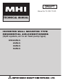
TECHNICAL MANUAL
INVERTER WALL MOUNTED TYPE
RESIDENTIAL AIR-CONDITIONERS
(Split system, air to air heat pump type)
SRK20ZM-S
25ZM-S
35ZM-S
50ZM-S
'10 • SRK-T-105
'13 • SRK-T-143D
CONTENTS
1. SPECIFICATIONS ........................................................................................
2. EXTERIOR DIMENSIONS
.........................................................................
(1) Indoor units ..........................................................................................
2
6
6
(2) Outdoor units .......................................................................................
(3) Remote control .....................................................................................
ELECTRICAL WIRING
..............................................................................
(1) Indoor units ..........................................................................................
(2) Outdoor units .......................................................................................
NOISE LEVEL
............................................................................................
PIPING SYSTEM
......................................................................................
RANGE OF USAGE & LIMITATIONS
.....................................................
7
3.
4.
5.
6.
7. CAPACITY TABLES ...................................................................................
8. APPLICATION DATA ..................................................................................
(1) Installation of indoor unit ......................................................................
(2) Installation of outdoor unit
..................................................................
9. OPTION PARTS ..........................................................................................
(1) Wired remote control (RC-E5) ..............................................................
(2) Interface kit (SC-BIKN-E) .....................................................................
(3) Super link E board (SC-ADNA-E) ..........................................................
10. TECHNICAL INFORMATION .......................................................................
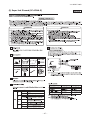
■How to read the model name
Example: SRK 20 ZM -S
Series code
Inverter type
Product capacity (Cooling capacity: 2.0kW)
Model name
-
-
SRK : Wall mounted type
SRC : Outdoor unit
9
10
10
11
13
17
19
21
23
23
27
35
35
41
45
47
'13 • SRK-T-143D
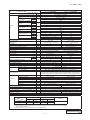
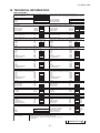
1. SPECIFICATIONS
SRK20ZM-S
Model
Indoor unit SRK20ZM-S
Outdoor unit SRC20ZM-S
Single phase, 220 - 240V, 50Hz
Nominal cooling capacity (range)
kW
2.0 ( 1.0 (Min.) - 2.7 (Max.))
Nominal heating capacity (range)
kW
2.7 ( 1.2 (Min.) - 3.9 (Max.))
Cooling
0.44 ( 0.21 - 0.77 )
Power
consumption
Heating
kW
0.62 ( 0.27 - 1.38 )
Max power consumption
1.65
Cooling
2.5 / 2.4 / 2.3 (220/ 230/ 240 V)
Running
current
Heating
A
3.2 / 3.1 / 3.0 (220/ 230/ 240 V)
Inrush current, max current
3.2 / 3.1 / 3.0 (220/ 230/ 240 V) Max. 9
Operation
Cooling
79.7
data
Power factor
%
Heating
87
EER
Cooling
4.55
COP
Heating
4.35
Cooling
49
59
Sound power level
Heating
52
58
Cooling
Hi: 33 Me: 27 Lo: 24 ULo: 21
47
dB(A)
Sound pressure level
Heating
Hi: 36 Me: 31 Lo: 24 ULo: 21
46
Silent mode sound pressure level
—
Cooling:42 / Heating:45
Exterior dimensions (Height x Width x Depth)
mm
294 x 798 x 229
540 x 780(+62) x 290
Exterior appearance
Fine snow
Stucco white
( Munsell color )
( 8.0Y 9.3/0.1 ) near equivalent
( 4.2Y 7.5/1.1 ) near equivalent
Net weight
kg
9.5
31.5
Compressor type & Q'ty
—
RM-B5077MDE1( Rotary type ) x 1
Compressor motor (Starting method)
kW
—
0.75 ( Inverter driven )
Refrigerant oil (Amount, type)
—
0.35 (DIAMOND FREEZE MA68)
Refrigerant (Type, amount, pre-charge length)
kg
R410A 0.75 in outdoor unit (incl. the amount for the piping of 15m )
Heat exchanger
Louver fins & inner grooved tubing
M fins & inner grooved tubing
Refrigerant control
Capillary tubes + Electronic expansion valve
Fan type & Q'ty
Tangential fan x 1
Propeller fan x 1
Fan motor (Starting method)
W
30 x1 (Direct drive)
24 x1 (Direct drive)
Cooling
Hi: 7.8 Me: 5.6 Lo: 5.3 ULo: 4.8
29.5
Air flow
m3/min
Heating
Hi: 9.8 Me: 6.3 Lo: 5.0 ULo: 4.5
25.6
Available external static pressure
Pa
0
0
Outside air intake
Not possible
—
Air filter, Quality / Quantity
Polypropylene net ( washable ) x 2
—
Shock & vibration absorber
Rubber sleeve (for fan motor)
Rubber sleeve (for fan motor & compressor)
Electric heater
—
—
Remote control
Wireless remote control
Operation
Room temperature control
Microcomputer thermostat
control
Operation display
RUN: Green, TIMER: Yellow, HI POWER: Green, 3D AUTO: Green
Compressor overheat protection, Overcurrent protection,
Safety equipments
Frost protection, Serial signal error protection, Indoor fan motor error protection,
Heating overload protection (High pressure control), Cooling overload protection
Refrigerant piping size (O.D)
mm
Liquid line :φ6.35 (1/4") Gas line :φ9.52 (3/8")
Connecting method
Flare connection
Flare connection
Attached length of piping
m
Liquid line : 0.53 / Gas line : 0.40
—
Installation
Insulation for piping
Necessary (Both sides), independent
data
Refrigerant line (one way) length
m
Max. 15
Vertical height diff. between O.U. and I.U.
m
Max. 10 (Outdoor unit is higher) / Max. 10 (Outdoor unit is lower)
Drain hose
Hose connectable ( VP 16 )
Holes φ20 x 2 pcs
Drain pump, max lift height
mm
—
—
Recommended breaker size
A
16
L.R.A. (Locked rotor ampere)
A
3.2 / 3.1 / 3.0 (220/ 230/ 240 V)
Interconnecting wires
Size x Core number
1.5mm2 x 4 cores (Including earth cable) / Terminal block (Screw fixing type)
IP number
IPX0
IPX4
Standard accessories
Mounting kit, Clean filter (Allergen clear filter x 1, Photocatalytic washable deodorizing filter x 1)
Option parts
Interface kit (SC-BIKN-E)
Item
Power source
Note (1) The data are measured at the following conditions.
Item
Indoor air temperature
The pipe length is 7.5m.
Outdoor air temperature
DB
WB
DB
WB
Cooling
27˚C
19˚C
35˚C
24˚C
Heating
20˚C
—
7˚C
6˚C
Operation
Standards
ISO5151-T1
(2) This air-conditioner is manufactured and tested in conformity with the ISO.
(3) Sound level indicates the value in an anechoic chamber. During operation these value are somewhat higher
due to ambient conditions.
(4) Select the breaker size according to the own national standard.
RWA000Z253 B
-
-
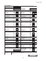
'13 • SRK-T-143D
SRK25ZM-S
Model
Indoor unit SRK25ZM-S
Outdoor unit SRC25ZM-S
Single phase, 220 - 240V, 50Hz
Nominal cooling capacity (range)
kW
2.5 ( 1.0 (Min.) - 2.9 (Max.))
Nominal heating capacity (range)
kW
3.2 ( 1.2 (Min.) - 4.2 (Max.))
Cooling
0.62 ( 0.21 - 0.88 )
Power
consumption
Heating
kW
0.80 ( 0.27 - 1.36 )
Max power consumption
1.65
Cooling
3.2 / 3.1 / 3.0 (220/ 230/ 240 V)
Running
current
Heating
A
4.0 / 3.8 / 3.7 (220/ 230/ 240 V)
Inrush current, max current
4.0 / 3.8 / 3.7 (220/ 230/ 240 V) Max. 9
Operation
Cooling
87
data
Power factor
%
Heating
91.5
EER
Cooling
4.03
COP
Heating
4.00
Cooling
50
60
Sound power level
Heating
55
61
Cooling
Hi: 34 Me: 28 Lo: 24 ULo: 21
48
dB(A)
Sound pressure level
Heating
Hi: 39 Me: 31 Lo: 24 ULo: 21
49
Silent mode sound pressure level
—
Cooling:42 / Heating:45
Exterior dimensions (Height x Width x Depth)
mm
294 x 798 x 229
540 x 780(+62) x 290
Exterior appearance
Fine snow
Stucco white
( Munsell color )
( 8.0Y 9.3/0.1 ) near equivalent
( 4.2Y 7.5/1.1 ) near equivalent
Net weight
kg
9.5
31.5
Compressor type & Q'ty
—
RM-B5077MDE1( Rotary type ) x 1
Compressor motor (Starting method)
kW
—
0.75 ( Inverter driven )
Refrigerant oil (Amount, type)
—
0.35 (DIAMOND FREEZE MA68)
Refrigerant (Type, amount, pre-charge length)
kg
R410A 0.75 in outdoor unit (incl. the amount for the piping of 15m )
Heat exchanger
Louver fins & inner grooved tubing
M fins & inner grooved tubing
Refrigerant control
Capillary tubes + Electronic expansion valve
Fan type & Q'ty
Tangential fan x 1
Propeller fan x 1
Fan motor (Starting method)
W
30 x1 (Direct drive)
24 x1 (Direct drive)
Cooling
Hi: 7.9 Me: 6.0 Lo: 5.3 ULo: 5.0
32.1
Air flow
m3/min
Heating
Hi: 10.6 Me: 6.5 Lo: 5.1 ULo: 4.6
25.6
Available external static pressure
Pa
0
0
Outside air intake
Not possible
—
Air filter, Quality / Quantity
Polypropylene net ( washable ) x 2
—
Shock & vibration absorber
Rubber sleeve (for fan motor)
Rubber sleeve (for fan motor & compressor)
Electric heater
—
—
Remote control
Wireless remote control
Operation
Room temperature control
Microcomputer thermostat
control
Operation display
RUN: Green, TIMER: Yellow, HI POWER: Green, 3D AUTO: Green
Compressor overheat protection, Overcurrent protection,
Safety equipments
Frost protection, Serial signal error protection, Indoor fan motor error protection,
Heating overload protection (High pressure control), Cooling overload protection
Refrigerant piping size (O.D)
mm
Liquid line :φ6.35 (1/4") Gas line :φ9.52 (3/8")
Connecting method
Flare connection
Flare connection
Attached length of piping
m
Liquid line : 0.53 / Gas line : 0.40
—
Installation
Insulation for piping
Necessary (Both sides), independent
data
Refrigerant line (one way) length
m
Max. 15
Vertical height diff. between O.U. and I.U.
m
Max. 10 (Outdoor unit is higher) / Max. 10 (Outdoor unit is lower)
Drain hose
Hose connectable ( VP 16 )
Holes φ20 x 2 pcs
Drain pump, max lift height
mm
—
—
Recommended breaker size
A
16
L.R.A. (Locked rotor ampere)
A
4.0 / 3.8 / 3.7 (220/ 230/ 240 V)
Interconnecting wires
Size x Core number
1.5mm2 x 4 cores (Including earth cable) / Terminal block (Screw fixing type)
IP number
IPX0
IPX4
Standard accessories
Mounting kit, Clean filter (Allergen clear filter x 1, Photocatalytic washable deodorizing filter x 1)
Option parts
Interface kit (SC-BIKN-E)
Item
Power source
Note (1) The data are measured at the following conditions.
Item
Indoor air temperature
The pipe length is 7.5m.
Outdoor air temperature
DB
WB
DB
WB
Cooling
27˚C
19˚C
35˚C
24˚C
Heating
20˚C
—
7˚C
6˚C
Operation
Standards
ISO5151-T1
(2) This air-conditioner is manufactured and tested in conformity with the ISO.
(3) Sound level indicates the value in an anechoic chamber. During operation these value are somewhat higher
due to ambient conditions.
(4) Select the breaker size according to the own national standard.
RWA000Z253 B
-
-
'13 • SRK-T-143D
SRK35ZM-S
Model
Indoor unit SRK35ZM-S
Outdoor unit SRC35ZM-S
Single phase, 220 - 240V, 50Hz
Nominal cooling capacity (range)
kW
3.5 ( 1.0 (Min.) - 3.8 (Max.))
Nominal heating capacity (range)
kW
4.0 ( 1.3 (Min.) - 4.8 (Max.))
Cooling
1.01 ( 0.21 - 1.24 )
Power
consumption
Heating
kW
1.00 ( 0.29 - 1.45 )
Max power consumption
1.65
Cooling
4.9 / 4.7 / 4.5 (220/ 230/ 240 V)
Running
current
Heating
A
4.9 / 4.7 / 4.5 (220/ 230/ 240 V)
Inrush current, max current
4.9 / 4.7 / 4.5 (220/ 230/ 240 V) Max. 9
Operation
Cooling
93.4
data
Power factor
%
Heating
92.5
EER
Cooling
3.47
COP
Heating
4.00
Cooling
58
62
Sound power level
Heating
59
63
Cooling
Hi: 42 Me: 32 Lo: 26 ULo: 22
50
dB(A)
Sound pressure level
Heating
Hi: 43 Me: 37 Lo: 25 ULo:22
51
Silent mode sound pressure level
—
Cooling:45 / Heating:45
Exterior dimensions (Height x Width x Depth)
mm
294 x 798 x 229
540 x 780(+62) x 290
Exterior appearance
Fine snow
Stucco white
( Munsell color )
( 8.0Y 9.3/0.1 ) near equivalent
( 4.2Y 7.5/1.1 ) near equivalent
Net weight
kg
9.5
34.5
Compressor type & Q'ty
—
RM-B5077MDE1( Rotary type ) x 1
Compressor motor (Starting method)
kW
—
0.90 ( Inverter driven )
Refrigerant oil (Amount, type)
—
0.35 (DIAMOND FREEZE MA68)
Refrigerant (Type, amount, pre-charge length)
kg
R410A 1.05 in outdoor unit (incl. the amount for the piping of 15m )
Heat exchanger
Louver fins & inner grooved tubing
M fins & inner grooved tubing
Refrigerant control
Capillary tubes + Electronic expansion valve
Fan type & Q'ty
Tangential fan x 1
Propeller fan x 1
Fan motor (Starting method)
W
30 x1 (Direct drive)
24 x1 (Direct drive)
Cooling
Hi: 10.1 Me: 6.4 Lo: 5.4 ULo: 5.0
31.5
Air flow
m3/min
Heating
Hi: 12.8 Me: 9.4 Lo: 6.1 ULo: 4.8
27.8
Available external static pressure
Pa
0
0
Outside air intake
Not possible
—
Air filter, Quality / Quantity
Polypropylene net ( washable ) x 2
—
Shock & vibration absorber
Rubber sleeve (for fan motor)
Rubber sleeve (for fan motor & compressor)
Electric heater
—
—
Remote control
Wireless remote control
Operation
Room temperature control
Microcomputer thermostat
control
Operation display
RUN: Green, TIMER: Yellow, HI POWER: Green, 3D AUTO: Green
Compressor overheat protection, Overcurrent protection,
Safety equipments
Frost protection, Serial signal error protection, Indoor fan motor error protection,
Heating overload protection (High pressure control), Cooling overload protection
Refrigerant piping size (O.D)
mm
Liquid line :φ6.35 (1/4") Gas line :φ9.52 (3/8")
Connecting method
Flare connection
Flare connection
Attached length of piping
m
Liquid line : 0.53 / Gas line : 0.40
—
Installation
Insulation for piping
Necessary (Both sides), independent
data
Refrigerant line (one way) length
m
Max. 15
Vertical height diff. between O.U. and I.U.
m
Max. 10 (Outdoor unit is higher) / Max. 10 (Outdoor unit is lower)
Drain hose
Hose connectable ( VP 16 )
Holes φ20 x 2 pcs
Drain pump, max lift height
mm
—
—
Recommended breaker size
A
16
L.R.A. (Locked rotor ampere)
A
4.9 / 4.7 / 4.5 (220/ 230/ 240 V)
Interconnecting wires
Size x Core number
1.5mm2 x 4 cores (Including earth cable) / Terminal block (Screw fixing type)
IP number
IPX0
IPX4
Standard accessories
Mounting kit, Clean filter (Allergen clear filter x 1, Photocatalytic washable deodorizing filter x 1)
Option parts
Interface kit (SC-BIKN-E)
Item
Power source
Note (1) The data are measured at the following conditions.
Item
Indoor air temperature
The pipe length is 7.5m.
Outdoor air temperature
DB
WB
DB
WB
Cooling
27˚C
19˚C
35˚C
24˚C
Heating
20˚C
—
7˚C
6˚C
Operation
Standards
ISO5151-T1
(2) This air-conditioner is manufactured and tested in conformity with the ISO.
(3) Sound level indicates the value in an anechoic chamber. During operation these value are somewhat higher
due to ambient conditions.
(4) Select the breaker size according to the own national standard.
RWA000Z253 B
-
-
'13 • SRK-T-143D
SRK50ZM-S
Model
Indoor unit SRK50ZM-S
Outdoor unit SRC50ZM-S
Single phase, 220 - 240V, 50Hz
Nominal cooling capacity (range)
kW
5.0 ( 1.6 (Min.) - 5.5 (Max.))
Nominal heating capacity (range)
kW
5.8 ( 1.6 (Min.) - 6.6 (Max.))
Cooling
1.55 ( 0.40 - 2.20 )
Power
consumption
Heating
kW
1.59 ( 0.42 - 2.10 )
Max power consumption
2.68
Cooling
7.1 / 6.8 / 6.5 (220/ 230/ 240 V)
Running
current
Heating
A
7.3 / 7.0 / 6.7 (220/ 230/ 240 V)
Inrush current, max current
7.3 / 7.0 / 6.7 (220/ 230/ 240 V) Max. 14
Operation
Cooling
99
data
Power factor
%
Heating
99
EER
Cooling
3.23
COP
Heating
3.65
Cooling
60
61
Sound power level
Heating
61
63
Cooling
Hi: 46 Me: 37 Lo: 28 ULo: 25
51
dB(A)
Sound pressure level
Heating
Hi: 45 Me: 37 Lo: 31 ULo:27
53
Silent mode sound pressure level
—
Cooling:43 / Heating:45
Exterior dimensions (Height x Width x Depth)
mm
294 x 798 x 229
640 x 800(+71) x 290
Exterior appearance
Fine snow
Stucco white
( Munsell color )
( 8.0Y 9.3/0.1 ) near equivalent
( 4.2Y 7.5/1.1 ) near equivalent
Net weight
kg
9.5
40.5
Compressor type & Q'ty
—
5RS132XAB21( Rotary type ) x 1
Compressor motor (Starting method)
kW
—
1.50 ( Inverter driven )
Refrigerant oil (Amount, type)
—
0.37 ( FV50S )
Refrigerant (Type, amount, pre-charge length)
kg
R410A 1.35 in outdoor unit (incl. the amount for the piping of 15m )
Heat exchanger
Louver fins & inner grooved tubing
M fins & inner grooved tubing
Refrigerant control
Capillary tubes + Electronic expansion valve
Fan type & Q'ty
Tangential fan x 1
Propeller fan x 1
Fan motor (Starting method)
W
30 x1 (Direct drive)
34 x1 (Direct drive)
Cooling
Hi: 11.3 Me: 7.8 Lo: 6.0 ULo: 5.3
36.0
Air flow
m3/min
Heating
Hi: 13.5 Me: 10.2 Lo: 7.5 ULo: 6.2
36.0
Available external static pressure
Pa
0
0
Outside air intake
Not possible
—
Air filter, Quality / Quantity
Polypropylene net ( washable ) x 2
—
Shock & vibration absorber
Rubber sleeve (for fan motor)
Rubber sleeve (for fan motor & compressor)
Electric heater
—
—
Remote control
Wireless remote control
Operation
Room temperature control
Microcomputer thermostat
control
Operation display
RUN: Green, TIMER: Yellow, HI POWER: Green, 3D AUTO: Green
Compressor overheat protection, Overcurrent protection,
Safety equipments
Frost protection, Serial signal error protection, Indoor fan motor error protection,
Heating overload protection (High pressure control), Cooling overload protection
Refrigerant piping size (O.D)
mm
Liquid line :φ6.35 (1/4") Gas line :φ12.7 (1/2")
Connecting method
Flare connection
Flare connection
Attached length of piping
m
Liquid line : 0.53 / Gas line : 0.40
—
Installation
Insulation for piping
Necessary (Both sides), independent
data
Refrigerant line (one way) length
m
Max. 25
Vertical height diff. between O.U. and I.U.
m
Max. 15 (Outdoor unit is higher) / Max. 15 (Outdoor unit is lower)
Drain hose
Hose connectable ( VP 16 )
Holes φ20 x 5 pcs
Drain pump, max lift height
mm
—
—
Recommended breaker size
A
16
L.R.A. (Locked rotor ampere)
A
7.3 / 7.0 / 6.7 (220/ 230/ 240 V)
Interconnecting wires
Size x Core number
1.5mm2 x 4 cores (Including earth cable) / Terminal block (Screw fixing type)
IP number
IPX0
IPX4
Standard accessories
Mounting kit, Clean filter (Allergen clear filter x 1, Photocatalytic washable deodorizing filter x 1)
Option parts
Interface kit (SC-BIKN-E)
Item
Power source
Note (1) The data are measured at the following conditions.
Item
Indoor air temperature
The pipe length is 7.5m.
Outdoor air temperature
DB
WB
DB
WB
Cooling
27˚C
19˚C
35˚C
24˚C
Heating
20˚C
—
7˚C
6˚C
Operation
Standards
ISO5151-T1
(2) This air-conditioner is manufactured and tested in conformity with the ISO.
(3) Sound level indicates the value in an anechoic chamber. During operation these value are somewhat higher
due to ambient conditions.
(4) Select the breaker size according to the own national standard.
RWA000Z253 B
-
-
48.9
47
45
D 55
B
585
450
A
403.6
471.6
531.8
Installation plate Unit
55
106.5
209
65 (Service space)
C
100 (Service space)
31
Space for installation and service when viewing from the front
E
50(Service space)
106.5
139
Outlet for down piping
(Refer to the above view)
798
60
45
294
790
47
60
7.7
279.1
7.2
(Service space)
-
15
229
45
3
B
C
D
E
F
G
A
(Option)
24
□120
Wired - remote control
60
19
Wireless remote control
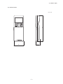
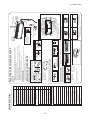
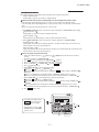
Notes(1)The model name label is attached
on the underside of the panel.
(2)It takes the interface kit(SC-BIKN-E)
to connect the wired remote controller.
Unit:mm
Content
(Flare)
Model 20∼35 : φ9.52(3/8")
50
: φ12.7(1/2")
(Flare)
Liquid piping
φ6.35(1/4")
(Flare)
Hole on wall for right rear piping (φ65)
Hole on wall for left rear piping (φ65)
Drain hose
VP16
Outlet for wiring
Outlet for piping(on both side)
Gas piping
G
F
Symbol
60
9
167
14.5
'13 • SRK-T-143D
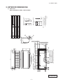
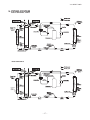
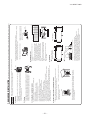
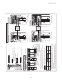
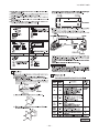
2. EXTERIOR DIMENSIONS
(1) Indoor units
Models SRK20ZM-S, 25ZM-S, 35ZM-S, 50ZM-S
RLA000Z054
290
540
63.4
69.4
111.6
D
390.6
390.6
780
510
E
158.4
12
61.9
17.9
24.3
312.5
B
138.4
14.8
50.6
42.5
33.5
40°
A
C
Terminal block
40°
97.7
-
15.8
Content
Service valve connection(gas side) φ9.52(3/8")
(Flare)
Service valve connection(liquid side) φ6.35(1/4")
(Flare)
Pipe/cable draw-out hole
φ20×2places
Drain discharge hole
Anchor bolt hole
M10×4places
351.6
Symbol
A
B
C
D
E
L1
L2
L3
L4
Dimensions
Examples of
installation
Intake
L2
L1
L3
(
L4
Service
space
I
I
280
75
80
Open
I
Open
100
100
250
280
Open
80
250
I
I
I
Minimum installation space
Outlet
Intake
180
Open
80
Open
IV
Unit:mm
)
Notes
(1)It must not be surrounded by walls on the four sides.
(2)The unit must be fixed with anchor bolts. An anchor bolt must not
protrude more than 15mm.
(3)Where the unit is subject to strong winds, lay it in such
a direction that the blower outlet faces perpendicularly
to the dominant wind direction.
(4)Leave 1m or more space above the unit.
(5)A wall in front of the blower outlet must not exceed the units height.
(6)The model name label is attached on the right side of the unit.
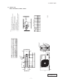
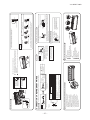
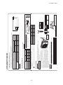
'13 • SRK-T-143D
(2) Outdoor units
Models SRC20ZM-S, 25ZM-S, 35ZM-S
RCV000Z019
290
43.5
640
90.6
38.6
89
327.3
327.3
520.6
510
800
D
161
201
12
50.6
71.2
17.9
E
351.6
B
148.4
Terminal block
A
33.5
C
Content
Service valve connection(gas side)
φ12.7(1/2")
(Flare)
Service valve connection(liquid side) φ6.35(1/4")
(Flare)
Pipe/cable draw-out hole
φ20×5places
Drain discharge hole
Anchor bolt hole
M10×4places
24.3
312.5
14.8
35.6
83.5
12.4
42.5
40°
93
Symbol
A
B
C
D
E
L1
L2
L3
L4
Dimensions
Outlet
Intake
L1
L3
I
I
280
75
80
Open
I
Open
100
100
250
L4
( Service
space )
180
Open
80
Open
280
Open
80
250
Unit:mm
IV
I
I
I
Minimum installation space
Examples of
installation
Intake
L2
Notes
(1)It must not be surrounded by walls on the four sides.
(2)The unit must be fixed with anchor bolts. An anchor bolt must not
protrude more than 15mm.
(3)Where the unit is subject to strong winds, lay it in such
a direction that the blower outlet faces perpendicularly
to the dominant wind direction.
(4)Leave 1m or more space above the unit.
(5)A wall in front of the blower outlet must not exceed the units height.
(6)The model name label is attached on the right side of the unit.
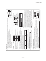
'13 • SRK-T-143D
Models SRC50ZM-S
40°
RCT000Z009
'13 • SRK-T-143D
(3) Remote control
167
Unit : mm
26
60
-
-
-
10 -
2
5
̪35,50
ONLY
̪
HD
CNF
㨪
CNS
DS
CNX
CNY
㨪
5
5
M
U
5
BACK-UP SW
WIRELESS
R-AMP
DISPLAY
8
CNE
Va
250V 3.15A
F
M
BL
BK
t
o
Th3
2
CNU
t
o
Th2
2
CNG
1 3 4 5 6
RD
PRINTED
CIRCUIT
BOARD
CNM
M
FMI
WH
SMI
Y
M
INTERFACE KIT
t
o
J
ThI
S/N
L
G
2
HEAT
EXCHANGER
Y/G
RD
3
Y/G
TO OUTDOOR
UNIT
1 2/N
BK
LM1
WH
LM2
T
HEAT
EXCHANGER
Power Source
1 Phase
220240V 50Hz
Color
Black
Blue
Red
White
Yellow
Yellow㧛Green
Mark
Description
Connector
Fan motor
Flap motor
Louver motor
Humidity sensor
Room temp. sensor
Heat exch. sensor
Diode stack
Fuse
Terminal block
Varistor
BK
BL
RD
WH
Y
Y㧛G
Item
CNE-CNY
FMI
SMI
LM1,2
HD
ThI
Th2,3
DS
F
T
Va
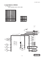
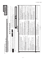
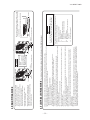
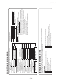
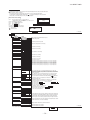
'13 • SRK-T-143D
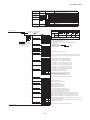
3. ELECTRICAL WIRING
(1) Indoor units
Models SRK20ZM-S, 25ZM-S, 35ZM-S, 50ZM-S
RWA000Z257
-
11 -
8(ZMX)
9(ZM)
2.0
Power cable size
(mm 2)
(Y/G)
(Y/G)
G2
G1
(RD) C-2
S.IN
NOISE
FILTER
32
F6
1.5
2
2
CNTH
T1
(Y)
L
T2
2
F2
Electric expansion valve(coil)
Fan motor
Reactor
Terminal block
Heat exchanger sensor(outdoor unit)
Outdoor air temp.sensor
Discharge pipe temp.sensor
Solenoid valve for 4 way valve
FMo
L
TB1
TH2
TH3
TH4
20S
250V 20A
U
V
W
Red
White
Yellow
Yellow/Green
RD
WH
Y
Y/G
Orange
Black
OR
Color
BK
M
FMo
CM
M
3∼
Mark
U (RD)
V (WH)
W (BK)
CNFAN
F3 250V 1A
N
P
PWB ASSY PWB1
POWER
TRANSISTOR
EEV
Connector
CN20S
CNTH
CNEEV
CNFAN
Description
PAM
CIRCUIT
Compressor motor
EEV
M
CNEEV
250V 10A
F4
+ +
CM
Item
SWITCHING
POWER
CIRCUIT
TH2 TH3 TH4
Earth wire size
(mm 2)
H
20S
CNHEAT
tࠑ
2
1.5mm2 x 3
F1
250V 3.15A
2
CN20S
250V 1A
Power cable length indoor-outdoor
wire size x number
(m)
(Y/G)
(WH)
(BK) 250V 15A (BK) R.IN
]
The specifications shown in the above table are for units without heaters. For units with heaters, refer
to the installation instructions or the construction instructions of the indoor unit.
Switchgear of Circuit breaker capacity which is calculated from MAX. over current should be chosen
along the regulations in each country.
The cable specifications are based on the assumption that a metal or plastic conduit is used with no
more than three cables contained in a conduit and a voltage drop is 2%. For an installation falling
outside of these conditions, please follow the internal cabling regulations. Adapt it to the regulation
in effect in each country.
35
25
20
Model MAX running current
(A)
2
N
3
1
3
L
TERMINAL
BLOCK
TB1
SIGNAL WIRE
POWER WIRES 1 2 N
Power cable, indoor-outdoor connecting wires
POWER SOURCE
∼220ー240V 50Hz/∼220V 60Hz
[
(OR)
TO INDOOR UNIT
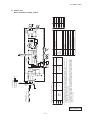
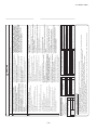
'13 • SRK-T-143D
(2) Outdoor units
Models SRC20ZM-S, 25ZM-S, 35ZM-S
RWC000Z272
-
12 -
SIGNAL WIRE
1 2
3
N
]
(Y/G)
N
3
2
1
(Y/G)
14
50
2.0
Power cable size
(mm2 )
F10
ROUT
18
2
R
2
CNTH
1.5
F8
2
F2
N
P
White
Yellow
YE
Y/G
Terminal block
Heat exchanger sensor(outdoor unit)
Outdoor air temp.sensor
Discharge pipe temp.sensor
Solenoid valve for 4 way valve
TB1,2
TH2
TH3
TH4
20S
Yellow/Green
Red
WH
Reactor
R
Orange
RD
Fan motor
FMo
OR
Electric expansion valve(coil)
EEV
Brown
Black
BR
Color
BK
FMo
M
CM
3∼
MS
Mark
W (BK)
V (WH)
U (RD)
CNFAN
W
V
U
POWER
TRANSISTOR
F3 250V 1A
250V 20A
Description
+
Compressor motor
EEV
M
CNEEV
+
CNEEV∼CN20S Connector
CM
Item
SWITCHING POWER
CIRCUIT
+
PWB ASSY (MAIN)
250V 20A ACTIVE
FILTER
UNIT
(YE)
T1
TH2 TH3 TH4
1.5mm2 x 3
(RD) C-2
CNSUB
Earth wire size
(mm 2)
(Y/G)
CNMAIN
G3
4(BK)
(WH) S-2
(WH) S
SO
S-1
(BK) R
RO
F1
indoor-outdoor
wire size x number
20S
2
CN20S
Power cable length
(m)
(Y/G) G1
(BR)
(WH) S IN
(BK) R IN
250V 3.15A
The specifications shown in the above table are for units without heaters. For units with heaters, refer
to the installation instructions or the construction instructions of the indoor unit.
Switchgear of Circuit breaker capacity which is calculated from MAX. over current should be chosen
along the regulations in each country.
The cable specifications are based on the assumption that a metal or plastic conduit is used with no
more than three cables contained in a conduit and a voltage drop is 2%. For an installation falling
outside of these conditions, please follow the internal cabling regulations. Adapt it to the regulation
in effect in each country.
MAX running current
(A)
Model
250V 20A
(BK) FUSE
Power cable, indoor-outdoor connecting wires
[
POWER WIRES
TO INDOOR UNIT
TB2
L
N
TERMINAL
BLOCK
TB1
PWB ASSY (SUB)
250V 10A
TERMINAL
BLOCK
(WH)
(OR)
T2
POWER SOURCE
∼220-240V 50Hz
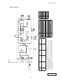
'13 • SRK-T-143D
Models SRC50ZM-S
RWC000Z269
'13 • SRK-T-143D
'09•SRK-DB-087D
4. NOISE LEVEL
SRK20ZM-S
4 NOISEModel
LEVEL
Condition
Model SRK20ZJ-S
ISO-T1, JIS C 9612
Mike position
(Indoor Unit)
Model
SRK20ZM-S
Cooling
33 dB(A)
Noise
Level
Heating
36 dB(A)
1m
0.8m
Unit
Mike position
(Center & Low points)
× ...... Cooling Heating
70
70
N70
Sound Pressure Level (dB)
(standard 2×10- 5 Pa )
60
60
N60 level in position as mentioned below
Mike position: at highest noise
Distance from front side 1m
50
50
N50
40
40
N40
Mike position
30
30
1m
N30
0.8m
Unit
Mike position
(Center & Low points)
20
20
N20
10
63
125
250
500
1000
2000
Mid Octave Band frequency (Hz)
(Outdoor Unit)
Model
SRC20ZM-S
Cooling
47 dB(A)
Noise
Level
Heating
46 dB(A)
10
8000
4000
Mike position: at highest noise level in position as mentioned below
Distance from front side 1m
× ...... Cooling Heating
70
70
N70
60
60
Sound Pressure Level (dB)
(standard 2×10- 5 P a )
N60
50
50
N50
40
40
N40
30
30
N30
20
20
N20
10
10
63
125
250
500
1000
2000
Mid Octave Band frequency (Hz)
-
13 -
4000
8000
'09•SRK-DB-087D
'13 • SRK-T-143D
Model SRK25ZM-S
Model SRK25ZJ-S
Condition
(Indoor Unit)
Model
SRK25ZM-S
Cooling
34 dB(A)
Noise
Level
Heating
39 dB(A)
ISO-T1, JIS C 9612
Mike position
1m
0.8m
Unit
× ...... Cooling Mike position
(Center & Low points)
Heating
70
70
N70
Sound Pressure Level (dB)
(standard 2×10- 5 Pa )
60
60
N60
Mike position: at highest noise level in position as mentioned below
Distance from front side 1m
50
50
N50
40
40
N40
30
30
Mike position
N30
1m
0.8m
20
Unit
20
Mike position
(Center & Low points)
N20
10
63
125
(Outdoor Unit)
Model
SRC25ZM-S
Cooling
48 dB(A)
Noise
Level
Heating
49 dB(A)
250
500
1000
2000
Mid Octave Band frequency (Hz)
4000
10
8000
Mike position: at highest noise level in position as mentioned below
Distance from front side 1m
× ...... Cooling 70
Heating
N70
60
70
60
Sound Pressure Level (dB)
(standard 2×10- 5 Pa )
N60
50
50
N50
40
40
N40
30
30
N30
20
20
N20
10
63
125
1000
2000
250
500
Mid Octave Band frequency (Hz)
-
14 -
4000
10
8000
'09•SRK-DB-087D
'13 • SRK-T-143D
Model SRK35ZM-S
Model SRK35ZJ-S
Condition
(Indoor Unit)
Model
SRK35ZM-S
42 dB(A)
Cooling
Noise
Level
43 dB(A)
Heating
ISO-T1, JIS C 9612
Mike position
1m
0.8m
Unit
× ...... Cooling Mike position
(Center & Low points)
Heating
70
70
N70
Sound Pressure Level (dB)
(standard 2×10- 5 Pa )
60
60
N60
Mike position: at highest noise level in position as mentioned below
Distance from front side 1m
50
50
N50
40
40
N40
30
30
Mike position
N30
1m
0.8m
20
Unit
20
Mike position
(Center & Low points)
N20
10
63
125
(Outdoor Unit)
Model
SRC35ZM-S
50 dB(A)
Cooling
Noise
Level
51 dB(A)
Heating
250
500
1000
2000
Mid Octave Band frequency (Hz)
4000
10
8000
Mike position: at highest noise level in position as mentioned below
Distance from front side 1m
× ...... Cooling Heating
70
70
N70
60
60
Sound Pressure Level (dB)
(standard 2×10- 5 Pa )
N60
50
50
N50
40
40
N40
30
30
N30
20
20
N20
10
63
125
250
500
1000
2000
Mid Octave Band frequency (Hz)
-
15 -
4000
10
8000
'13 • SRK-T-143D
Model SRK50ZM-S
Condition
(Indoor Unit)
Model
SRK50ZM-S
Cooling
46 dB(A)
Noise
Level
Heating
45 dB(A)
ISO-T1,JIS C 9612
Mike position
1m
0.8m
Unit
× ...... Cooling
Mike position
(Center & Low points)
Heating
70
70
N70
Sound Pressure Level (dB)
(standard 2×10⁻⁵ Pa )
60
60
N60
Mike position: at highest noise level in position as mentioned below
Distance from front side 1m
50
50
N50
40
40
N40
30
30
Mike position
N30
1m
0.8m
20
10
Unit
63
125
250
500
20
Mike position
(Center & Low points)
1000
2000
N20
10
8000
4000
Mid Octave Band frequency (Hz)
(Outdoor Unit)
Model
SRC50ZM-S
Cooling
51 dB(A)
Noise
Level
Heating
53 dB(A)
Mike position: at highest noise level in position as mentioned below
Distance from front side 1m
× ...... Cooling
Heating
70
70
N70
Sound Pressure Level (dB)
(standard 2×10⁻⁵ P a)
60
60
N60
50
50
N50
40
40
N40
30
30
N30
20
20
N20
10
63
125
250
500
1000
Mid Octave Band frequency (Hz)
-
16 -
2000
4000
10
8000
'09•SRK-DB-087D
'13 • SRK-T-143D
5.
5 PIPING SYSTEM
Models SRK20ZM-S, 25ZM-S
pipe
Model SRK35ZM-S
pipe
Humidity
sensor
(HD)
-
17 -
'13 • SRK-T-143D
Model
Model SRK50ZM-S
SRK50ZM-S
Cooling cycle
Indoor unit
Flare
connection
Gas pipe
Heat
(φ12.7)
exchanger
sensor
(Th3)
Room temp.
sensor
(Th1)
Heating cycle
Outdoor unit
Service valve
(Gas)
Discharge pipe
temp. sensor
(TH3)
Check joint
Heat
exchanger
Heat
exchanger
Heat
exchanger
sensor
(Th2)
Muffler
Muffler
4way valve
Humidity
sensor
(HD)
Outdoor air
temp. sensor
(TH2)
Compressor
Receiver
Liquid
pipe
(φ6.35)
Flare connection
Capillary tube
Electronic
expansion valve
(EEV)
Capillary tube
Service valve
(Liquid)
Strainer
Heat
exchanger
sensor
(TH1)
Muffler
Models SRK20ZJX-S, 25ZJX-S, 35ZJX-S
Cooling cycle
Indoor unit
Room temp.
sensor
(Th1)
Flare
connection
Gas pipie
Heat
(φ9.52)
exchanger
sensor
(Th22)
Service valve
(Gas)
Discharge pipe
temp. sensor
(TH3)
Check joint
4way valve
*1
Humidity
sensor
(Th3)
Heating cycle
Outdoor unit
Muffler
Muffler
Accumulator
Heat
exchanger
Heat
exchanger
Heat
exchanger
sensor
(Th21)
Outdoor air
temp. sensor
(TH2)
Compressor
Liquid
pipe
(φ6.35)
Flare connection
Heat
exchanger
sensor
(TH1)
Capillary tube
Electronic
expansion valve
(EEV)
Capillary tube
Service valve
(Liquid)
Strainer
Strainer
*1. SRF series only.
-
18 -
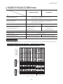
'13 • SRK-T-143D
OFOF
USAGE
& LIMITATIONS
6. RANGE
RANGE
USAGE
& LIMITATIONS
Models
SRK20,25,35ZM-S
SRK50ZM-S
Item
Indoor return air temperature
(Upper, lower limits)
Cooling operation : Approximately 18 to 32℃ D.B.
Heating operation : Approximately 10 to 30℃ D.B.
(Refer to the selection chart)
Outdoor air temperature
(Upper, lower limits)
Cooling operation : Approximately -15 to 46℃ D.B.
Heating operation : Approximately -15 to 24℃ D.B.
(Refer to the selection chart)
Refrigerant line (one way) length
Max. 15m
Max. 25m
Vertical height difference between
outdoor unit and indoor unit
Max. 10m
(Outdoor unit is higher)
Max. 10m
(Outdoor unit is lower)
Max. 15m
(Outdoor unit is higher)
Max. 15m
(Outdoor unit is lower)
Power source voltage
Rating ±10%
Voltage at starting
Min. 85% of rating
Max. 4 times/h
(Inching prevention 10 minutes)
Frequency of ON-OFF cycle
ON and OFF interval
Max. 7 times/h
(Inching prevention 5 minutes)
Min. 3 minutes
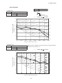
Selection chart
Correct the cooling and heating capacity in accordance with the conditions as follows. The net cooling and heating capacity can be
obtained in the following way.
Net capacity = Capacity shown on specification × Correction factors as follows.
(1) Coefficient of cooling and heating capacity in relation to temperatures
Coefficient of cooling &
heating capacity in
relation to temperature
1.3
1.2
Cooling
1.1
1.0
Heating
0.9
0.8
0.7
0.6
Cooling operation
Outdoor air D.B.
temperature
°C D. B.
Applicable range
46
40
35
30
25
20
26
24
Heating operation
Indoor air D.B.
temperature
°C D. B.
0
-5
-10
-15
Depends on installed situation
14
16
18
20
22
Indoor air W.B. temperature °C W.B. ISO-T1 Standard Condition
27
25
20
15
10
-15
-10
-5
0
10
15
ISO-T1 Standard Condition
Outdoor air W.B. temperature °C W.B.
-
19 -
5
'09•SRK-DB-087D
'13
• SRK-T-143D
(2) Correction of cooling and heating capacity in relation to one way length of refrigerant piping
Piping length [m]
7
10
15
20
25
30
Cooling
1.0
0.99
0.975
0.965
0.95
0.935
Heating
1.0
1.0
1.0
1.0
1.0
1.0
(3) Correction relative to frosting on outdoor heat exchanger during heating
Air inlet temperature of
outdoor unit in °CWB
-15
-10
-9
-7
-5
-3
-1
1
3
5 or more
Adjustment coefficient
0.95
0.95
0.94
0.93
0.91
0.88
0.86
0.87
0.92
1.00
How to obtain the cooling and heating capacity
=
-
20 -
'13 • SRK-T-143D
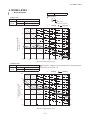
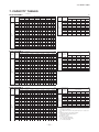
7. CAPACITY TABLES
Model SRK20ZM-S
Cooling Mode
(kW)
Heating Mode (HC)
(kW)
Indoor air temp
Air flow
Hi
7.8
3
(m /min)
Outdoor
air temp.
21˚CDB
23˚CDB
26˚CDB
27˚CDB
28˚CDB
31˚CDB
33˚CDB
14˚CWB
16˚CWB
18˚CWB
19˚CWB
20˚CWB
22˚CWB
24˚CWB
Air flow
Indoor air temp
outdoor
air temp.
16˚CDB
18˚CDB
20˚CDB
22˚CDB
24˚CDB
TC
SHC
TC
SHC
TC
SHC
TC
SHC
TC
SHC
TC
SHC
TC
SHC
-15˚CWB
1.66
1.63
1.59
1.55
1.52
10
2.25
1.93
2.36
1.90
2.45
1.99
2.49
1.96
2.53
1.94
2.60
2.02
2.67
1.97
-10˚CWB
1.88
1.85
1.82
1.78
1.74
12
2.21
1.91
2.32
1.88
2.41
1.97
2.45
1.95
2.50
1.93
2.58
2.01
2.65
1.96
-5˚CWB
2.04
2.01
1.97
1.94
1.91
14
2.17
1.89
2.28
1.86
2.38
1.96
2.42
1.94
2.47
1.91
2.55
2.00
2.62
1.95
0˚CWB
2.13
2.10
2.07
2.04
2.01
16
2.13
1.87
2.24
1.85
2.34
1.94
2.39
1.92
2.43
1.90
2.52
1.99
2.59
1.94
5˚CWB
2.72
2.69
2.67
2.62
2.58
18
2.08
1.85
2.19
1.82
2.30
1.92
2.35
1.90
2.40
1.88
2.49
1.98
2.56
1.93
6˚CWB
2.76
2.73
2.70
2.67
2.63
20
2.04
1.83
2.15
1.81
2.26
1.91
2.31
1.89
2.36
1.87
2.45
1.97
2.53
1.92
10˚CWB
2.94
2.91
2.89
2.85
2.82
22
1.99
1.81
2.10
1.78
2.22
1.89
2.28
1.88
2.32
1.86
2.42
1.95
2.50
1.91
15˚CWB
3.20
3.17
3.14
3.11
3.08
24
1.94
1.78
2.05
1.76
2.18
1.88
2.24
1.86
2.28
1.85
2.38
1.94
2.47
1.90
20˚CWB
3.43
3.41
3.39
3.35
3.32
26
1.90
1.76
2.01
1.74
2.14
1.86
2.20
1.85
2.24
1.83
2.35
1.93
2.43
1.89
28
1.85
1.74
1.96
1.72
2.09
1.84
2.15
1.83
2.20
1.82
2.31
1.92
2.40
1.88
30
1.79
1.70
1.90
1.70
2.05
1.83
2.11
1.82
2.16
1.80
2.27
1.90
2.36
1.87
32
1.74
1.65
1.85
1.68
2.00
1.81
2.07
1.80
2.12
1.79
2.23
1.89
2.32
1.86
34
1.69
1.60
1.80
1.65
1.95
1.79
2.02
1.78
2.07
1.77
2.19
1.88
2.28
1.85
35
1.66
1.58
1.77
1.64
1.93
1.78
2.00
1.78
2.05
1.76
2.17
1.87
2.26
1.84
36
1.63
1.55
1.74
1.62
1.90
1.77
1.98
1.77
2.02
1.75
2.15
1.87
2.24
1.83
38
1.58
1.50
1.68
1.60
1.85
1.75
1.93
1.75
1.98
1.74
2.11
1.85
2.20
1.82
39
1.55
1.47
1.66
1.57
1.83
1.74
1.91
1.74
1.95
1.73
2.08
1.84
2.18
1.81
Model SRK25ZM-S
Cooling Mode
Hi
9.8
(m3/min)
(kW)
Heating Mode (HC)
(kW)
Indoor air temp
Air flow
Hi
7.9
(m3/min)
Outdoor
air temp.
21˚CDB
23˚CDB
26˚CDB
27˚CDB
28˚CDB
31˚CDB
33˚CDB
14˚CWB
16˚CWB
18˚CWB
19˚CWB
20˚CWB
22˚CWB
24˚CWB
TC
SHC
TC
SHC
TC
SHC
TC
SHC
TC
SHC
TC
SHC
TC
SHC
10
2.82
2.23
2.95
2.19
3.06
2.27
3.11
2.24
3.16
2.21
3.26
2.28
3.34
2.21
12
2.77
2.20
2.90
2.17
3.01
2.25
3.07
2.22
3.12
2.20
3.22
2.27
3.31
2.20
14
2.71
2.17
2.85
2.14
2.97
2.23
3.03
2.21
3.08
2.18
3.18
2.25
3.28
2.19
16
2.66
2.15
2.80
2.12
2.92
2.21
2.98
2.19
3.04
2.16
3.15
2.24
3.24
2.18
18
2.60
2.12
2.74
2.09
2.88
2.19
2.94
2.17
2.99
2.14
3.11
2.22
3.20
2.17
20
2.55
2.09
2.68
2.07
2.83
2.17
2.89
2.14
2.95
2.12
3.07
2.21
3.17
2.15
22
2.49
2.06
2.63
2.04
2.78
2.14
2.84
2.12
2.90
2.10
3.02
2.20
3.13
2.14
24
2.43
2.03
2.57
2.01
2.72
2.12
2.80
2.11
2.85
2.08
2.98
2.18
3.08
2.13
26
2.37
2.00
2.51
1.98
2.67
2.10
2.74
2.09
2.80
2.07
2.93
2.16
3.04
2.11
28
2.31
1.97
2.44
1.96
2.61
2.08
2.69
2.07
2.75
2.05
2.89
2.14
3.00
2.10
30
2.24
1.94
2.38
1.92
2.56
2.05
2.64
2.05
2.70
2.03
2.84
2.13
2.95
2.08
32
2.18
1.91
2.31
1.89
2.50
2.03
2.58
2.03
2.64
2.01
2.79
2.11
2.90
2.07
34
2.11
1.88
2.25
1.87
2.44
2.01
2.53
2.00
2.59
1.99
2.74
2.09
2.85
2.05
35
2.08
1.87
2.21
1.85
2.41
1.99
2.50
1.99
2.56
1.97
2.71
2.08
2.83
2.04
36
2.04
1.85
2.18
1.84
2.38
1.98
2.47
1.98
2.53
1.96
2.69
2.08
2.80
2.03
38
1.97
1.82
2.11
1.81
2.32
1.96
2.41
1.96
2.47
1.94
2.63
2.05
2.75
2.02
39
1.94
1.80
2.07
1.79
2.28
1.94
2.38
1.94
2.44
1.93
2.61
2.05
2.72
2.01
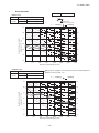
Model SRK35ZM-S
Cooling Mode
Air flow
Hi
10.6
3
(m /min)
indoor air temp
outdoor
air temp.
16˚CDB
18˚CDB
20˚CDB
22˚CDB
24˚CDB
-15˚CWB
1.97
1.93
1.88
1.84
1.80
-10˚CWB
2.23
2.19
2.16
2.10
2.06
-5˚CWB
2.41
2.38
2.33
2.30
2.27
0˚CWB
2.53
2.49
2.45
2.42
2.38
5˚CWB
3.22
3.19
3.17
3.10
3.06
6˚CWB
3.27
3.24
3.20
3.16
3.12
10˚CWB
3.48
3.45
3.42
3.38
3.34
15˚CWB
3.79
3.75
3.73
3.69
3.65
20˚CWB
4.07
4.04
4.02
3.97
3.94
Heating Mode (HC)
(kW)
(kW)
Indoor air temp
Air flow
Hi
10.1
3
(m /min)
Outdoor
air temp.
21˚CDB
23˚CDB
26˚CDB
27˚CDB
28˚CDB
31˚CDB
33˚CDB
14˚CWB
16˚CWB
18˚CWB
19˚CWB
20˚CWB
22˚CWB
24˚CWB
TC
SHC
TC
SHC
TC
SHC
TC
SHC
TC
SHC
TC
SHC
TC
SHC
10
3.94
3.00
4.13
2.95
4.28
3.04
4.35
3.00
4.43
2.97
4.56
3.04
4.68
2.94
12
3.87
2.97
4.06
2.92
4.22
3.02
4.29
2.98
4.37
2.94
4.51
3.02
4.63
2.93
14
3.80
2.93
3.99
2.88
4.16
2.99
4.24
2.96
4.31
2.91
4.46
3.00
4.59
2.91
16
3.72
2.89
3.91
2.85
4.09
2.96
4.18
2.93
4.25
2.89
4.40
2.98
4.54
2.89
18
3.65
2.85
3.84
2.81
4.03
2.93
4.11
2.90
4.19
2.87
4.35
2.96
4.49
2.88
20
3.57
2.81
3.76
2.77
3.96
2.90
4.05
2.87
4.13
2.84
4.29
2.94
4.43
2.85
22
3.49
2.77
3.68
2.73
3.89
2.86
3.98
2.83
4.06
2.80
4.23
2.92
4.38
2.84
24
3.40
2.72
3.59
2.69
3.81
2.83
3.91
2.81
3.99
2.78
4.17
2.89
4.32
2.81
26
3.32
2.68
3.51
2.65
3.74
2.80
3.84
2.78
3.92
2.75
4.11
2.86
4.26
2.80
28
3.23
2.63
3.42
2.61
3.66
2.77
3.77
2.76
3.85
2.72
4.04
2.84
4.20
2.77
30
3.14
2.59
3.33
2.57
3.58
2.74
3.70
2.72
3.78
2.70
3.98
2.82
4.13
2.75
32
3.05
2.54
3.24
2.52
3.50
2.70
3.62
2.69
3.70
2.66
3.91
2.79
4.06
2.73
34
2.95
2.50
3.14
2.48
3.41
2.66
3.54
2.66
3.62
2.63
3.84
2.77
4.00
2.69
35
2.91
2.48
3.10
2.46
3.37
2.65
3.50
2.64
3.58
2.62
3.80
2.75
3.96
2.68
36
2.86
2.46
3.05
2.44
3.33
2.63
3.46
2.63
3.54
2.60
3.76
2.72
3.92
2.67
38
2.76
2.41
2.95
2.40
3.24
2.59
3.38
2.59
3.46
2.57
3.69
2.70
3.85
2.65
39
2.71
2.39
2.90
2.37
3.20
2.57
3.33
2.58
3.42
2.56
3.65
2.69
3.81
2.64
-
21 -
Air flow
Hi
12.8
(m3/min)
indoor air temp
outdoor
air temp.
16˚CDB
18˚CDB
20˚CDB
22˚CDB
24˚CDB
-15˚CWB
2.46
2.41
2.35
2.30
2.25
-10˚CWB
2.79
2.74
2.70
2.63
2.58
-5˚CWB
3.02
2.97
2.91
2.88
2.83
0˚CWB
3.16
3.12
3.06
3.02
2.98
5˚CWB
4.03
3.98
3.96
3.88
3.83
6˚CWB
4.09
4.04
4.00
3.95
3.90
10˚CWB
4.35
4.31
4.28
4.22
4.18
15˚CWB
4.73
4.69
4.66
4.61
4.56
20˚CWB
5.09
5.05
5.02
4.96
4.92
Note(1) These data show average statuses.
Depending on the system control, there may be ranges where the operation is
not conducted continuously.
These data show the case where the operation frequency of a compressor is
fixed.
(2) Capacities are based on the following conditions.
Corresponding refrigerant piping length :7m
Level difference of Zero.
(3) Symbols are as follows.
TC : Total cooling capacity (kW)
SHC : Sensible heat capacity (kW)
HC : Heating capacity (kW)
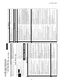
'13 • SRK-T-143D
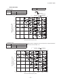
Model SRK50ZM-S
Cooling Mode
(kW)
Heating Mode (HC)
(kW)
Indoor air temp
Air flow
Hi
11.3
(m3/min)
Outdoor
air temp.
21˚CDB
23˚CDB
26˚CDB
27˚CDB
28˚CDB
31˚CDB
33˚CDB
Air flow
indoor air temp
outdoor
air temp.
16˚CDB
18˚CDB
20˚CDB
22˚CDB
24˚CDB
TC
SHC
TC
SHC
TC
SHC
TC
SHC
TC
SHC
TC
SHC
TC
SHC
-15˚CWB
3.57
3.49
3.41
3.34
3.26
10
5.63
4.09
5.90
4.02
6.11
4.12
6.22
4.05
6.32
3.99
6.51
4.05
6.69
3.92
-10˚CWB
4.04
3.97
3.91
3.81
3.73
12
5.53
4.03
5.80
3.97
6.03
4.07
6.14
4.01
6.25
3.96
6.44
4.02
6.62
3.89
-5˚CWB
4.37
4.31
4.22
4.18
4.11
14
5.43
3.98
5.70
3.91
5.94
4.03
6.05
3.98
6.16
3.92
6.37
4.00
6.55
3.86
0˚CWB
4.59
4.52
4.44
4.39
4.32
16
5.32
3.92
5.59
3.86
5.85
3.98
5.96
3.93
6.08
3.88
6.29
3.96
6.48
3.84
5˚CWB
5.84
5.77
5.74
5.63
5.55
18
5.21
3.85
5.48
3.80
5.75
3.94
5.88
3.90
5.99
3.84
6.21
3.93
6.41
3.81
6˚CWB
5.94
5.87
5.80
5.73
5.66
20
5.10
3.79
5.37
3.74
5.65
3.89
5.78
3.85
5.90
3.80
6.13
3.90
6.33
3.78
10˚CWB
6.31
6.25
6.21
6.12
6.06
22
4.98
3.73
5.25
3.68
5.55
3.84
5.69
3.81
5.80
3.76
6.05
3.86
6.25
3.75
15˚CWB
6.86
6.80
6.76
6.68
6.62
24
4.86
3.67
5.14
3.62
5.45
3.79
5.59
3.76
5.71
3.72
5.96
3.83
6.17
3.72
20˚CWB
7.38
7.32
7.28
7.20
7.14
26
4.74
3.60
5.01
3.56
5.34
3.74
5.49
3.71
5.61
3.67
5.87
3.79
6.08
3.69
28
4.61
3.54
4.89
3.50
5.23
3.69
5.39
3.67
5.50
3.63
5.78
3.76
5.99
3.66
30
4.49
3.46
4.76
3.43
5.11
3.64
5.28
3.62
5.40
3.58
5.68
3.72
5.90
3.62
32
4.35
3.40
4.63
3.37
5.00
3.58
5.17
3.57
5.29
3.54
5.58
3.68
5.81
3.59
34
4.22
3.33
4.49
3.31
4.88
3.52
5.06
3.52
5.18
3.49
5.48
3.64
5.71
3.55
35
4.15
3.29
4.42
3.27
4.82
3.49
5.00
3.49
5.12
3.45
5.43
3.62
5.66
3.53
36
4.08
3.26
4.35
3.24
4.76
3.47
4.94
3.46
5.06
3.43
5.37
3.60
5.61
3.50
38
3.94
3.19
4.21
3.18
4.63
3.42
4.82
3.42
4.94
3.39
5.27
3.54
5.50
3.47
39
3.87
3.15
4.14
3.14
4.57
3.39
4.76
3.39
4.88
3.36
5.21
3.52
5.45
3.45
14˚CWB
16˚CWB
18˚CWB
19˚CWB
20˚CWB
22˚CWB
-
24˚CWB
22 -
Hi
13.5
3
(m /min)
Note(1) These data show average statuses.
Depending on the system control, there may be ranges where the operation is
not conducted continuously.
These data show the case where the operation frequency of a compressor is
fixed.
(2) Capacities are based on the following conditions.
Corresponding refrigerant piping length :7m
Level difference of Zero.
(3) Symbols are as follows.
TC : Total cooling capacity (kW)
SHC : Sensible heat capacity (kW)
HC : Heating capacity (kW)
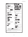
RLA012A020
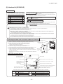
• A wired remote control unit is supplied separately as an optional part.
• When install the unit, be sure to check whether the selection of
installation place, power supply specifications, usage limitation (piping
length, height differences between indoor and outdoor units, power
supply voltage and etc.) and installation spaces.
Never do it under any
circumstances.
-
23 -
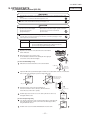
Standard accessories (Installation kit)
○ Before installation check that the power supply matches the air conditioner.
CAUTION
○ Where there is no obstructions to the air flow and where the cooled and heated air can be evenly distributed.
5 cm m
inim
from the um
wall
• Do not install the unit in the locations listed below.
• Locations where carbon fiber, metal powder or any powder is floating.
• Locations where any substances that can affect the unit such as sulphide
gas, chloride gas, acid and alkaline can occur.
• Vehicles and ships.
• Locations where cosmetic or special sprays are often used.
• Locations with direct exposure of oil mist and steam such as kitchen and
machine plant.
• Locations where any machines which generate high frequency harmonics
are used.
• Locations with salty atmospheres such as coastlines.
• Locations with heavy snow (If installed, be sure to provide base flame and
snow hood mentioned in the manual).
• Locations where the unit is exposed to chimney smoke.
• Locations at high altitude (more than 1000m high).
• Locations with ammonic atmospheres.
• Locations where heat radiation from other heat source can affect the unit.
• Locations without good air circulation.
• Locations with any obstacles which can prevent inlet and outlet air of the unit.
• Locations where short circuit of air can occur (in case of multiple units
installation).
• Locations where strong air blows against the air outlet of outdoor unit.
• Locations where something located above the unit could fall.
It can cause remarkable decrease in performance, corrosion and damage
of components, malfunction and fire.
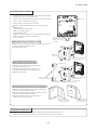
• Do not install the indoor unit in the locations listed below (Be sure
to install the indoor unit according to the installation manual for
each model because each indoor unit has each limitation).
• Locations with any obstacles which can prevent inlet and outlet air of the
unit.
• Locations where vibration can be amplified due to insufficient strength of
structure.
• Locations where the infrared receiver is exposed to the direct sunlight or
the strong light beam (in case of the infrared specification unit).
• Locations where an equipment affected by high harmonics is placed (TV
set or radio receiver is placed within 1m).
• Locations where drainage cannot run off safely.
It can affect performance or function and etc.
• Do not install the unit near the location where leakage of
combustible gases can occur.
• Use the circuit breaker of correct capacity. Circuit breaker should
be the one that disconnect all poles under over current.
Using the incorrect one could cause the system failure and fire.
• Install isolator or disconnect switch on the power supply wiring in
accordance with the local codes and regulations.
The isolator should be locked in OFF state in accordance with EN60204-1.
• Be sure to install indoor unit properly according to the installation
manual in order to run off the drainage smoothly.
Improper installation of indoor unit can cause dropping water into the room
and damaging personal property.
• Install the drainage pipe to run off drainage securely according to
the installation manual.
Incorrect installation of the drainage pipe can cause dropping water into the
room and damaging personal property.
• Be sure to install the drainage pipe with descending slope of 1/100
or more, and not to make traps and air-bleedings.
Check if the drainage runs off securely during commissioning and ensure
the space for inspection and maintenance.
• Secure a space for installation, inspection and maintenance
specified in the manual.
Insufficient space can result in accident such as personal injury due to
Installation board
6.5 cm minimum from the ceiling
If leaked gases accumulate around the unit, it can cause fire.
• Do not install the unit where corrosive gas (such as sulfurous acid
gas etc.) or combustible gas (such as thinner and petroleum gases)
can accumulate or collect, or where volatile combustible
substances are handled.
Corrosive gas can cause corrosion of heat exchanger, breakage of plastic
parts and etc. And combustible gas can cause fire.
• Do not use the indoor unit at the place where water splashes may
occur such as in laundries.
Since the indoor unit is not waterproof, it can cause electric shocks and fire.
• Do not install nor use the system close to the equipment that
generates electromagnetic fields or high frequency harmonics.
Equipment such as inverters, standby generators, medical high frequency
equipments and telecommunication equipments can affect the system, and
cause malfunctions and breakdowns. The system can also affect medical
equipment and telecommunication equipment, and obstruct its function or
cause jamming.
• Do not place any variables which will be damaged by getting wet
under the indoor unit.
When the relative humidity is higher than 80% or drainage pipe is clogged,
condensation or drainage water can drop and it can cause the damage of
valuables.
• Do not install the wireless remote control at the direct sunlight.
It can cause malfunction or deformation of the wireless remote control.
• Do not use the unit for special purposes such as storing foods,
cooling precision instruments and preservation of animals, plants or
art.
It can cause the damage of the items.
• Do not use any materials other than a fuse with the correct rating in
the location where fuses are to be used.
Connecting the circuit with copper wire or other metal thread can cause
unit failure and fire.
• Do not touch any buttons with wet hands.
It can cause electric shocks.
• Do not touch any refrigerant pipes with your hands when the
system is in operation.
During operation the refrigerant pipes become extremely hot or extremely
cold depending the operating condition, and it can cause burn injury or
frost injury.
falling from the installation place.
• For installation work, be careful not to get injured with the heat
exchanger, piping flare portion or screws etc.
• Be sure to insulate the refrigerant pipes so as not to condense the
ambient air moisture on them.
Insufficient insulation can cause condensation, which can lead to moisture
damage on the ceiling, floor, furniture and any other valuables.
• When perform the air conditioner operation (cooling or drying operation) in which ventilator is installed in the room. In this case, using the
air conditioner in parallel with the ventilator, there is the possibility
that drain water may backflow in accordance with the room lapse into
the negative pressure status. Therefore, set up the opening port such
as incorporate the air into the room that may appropriate to ventilation (For example; Open the door a little). In addition, just as above, so
set up the opening port if the room lapse into negative pressure status
due to register of the wind for the high rise apartment etc.
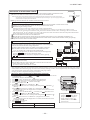
• Be sure to perform air tightness test by pressurizing with nitrogen
gas after completed refrigerant piping work.
If the density of refrigerant exceeds the limit in the event of refrigerant
leakage in the small room, lack of oxygen can occur, which can cause
serious accidents.
• Carry out the electrical work for ground lead with care.
Do not connect the ground lead to the gas line, water line, lightning conductor or telephone line’s ground lead. Incorrect grounding can cause unit faults
such as electric shocks due to short-circuiting.
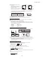
(Install at location that meets the following conditions, after getting approval from the customer)
Indoor unit
WARNING
• Do not vent R410A into the atmosphere : R410A is a fluorinated
• Do not perform any change of protective device itself or its setup
greenhouse gas, covered by the Kyoto Protocol with Groval
condition.
Warming Potential (GWP)=1975.
The forced operation by short-circuiting protective device of pressure
• Do not run the unit with removed panels or protections.
switch and temperature controller or the use of non specified component
Touching rotating equipments, hot surfaces or high voltage parts can cause can cause fire or burst.
personal injury due to entrapment, burn or electric shocks.
SELECTION OF INSTALLATION LOCATION
• Do not processing, splice the power cord, or share a socket with
other power plugs.
This may cause fire or electric shock due to defecting contact, defecting
insulation and over-current etc.
• Do not bundling, winding or processing for the power cord. Or, do
not deforming the power plug due to tread it.
This may cause fire or heating.
• Do not put the drainage pipe directly into drainage channels where
poisonous gases such as sulphide gas can occur.
Poisonous gases will flow into the room through drainage pipe and
seriously affect the user’s health and safety. This can also cause the
corrosion of the indoor unit and a resultant unit failure or refrigerant leak.
• Ensure that no air enters in the refrigerant circuit when the unit is
installed and removed.
If air enters in the refrigerant circuit, the pressure in the refrigerant circuit
becomes too high, which can cause burst and personal injury.
BEFORE INSTALLATION
• Tighten the flare nut by torque wrench with specified method.
If the flare nut were tightened with excess torque, this may cause burst and
refrigerant leakage after a long period.
• The electrical installation must be carried out by the qualified
electrician in accordance with “the norm for electrical work” and
“national wiring regulation”, and the system must be connected to
the dedicated circuit.
Power supply with insufficient capacity and incorrect function done by
improper work can cause electric shocks and fire.
• Be sure to shut off the power before starting electrical work.
Failure to shut off the power can cause electric shocks, unit failure or
incorrect function of equipment.
• Be sure to use the cables conformed to safety standard and cable
ampacity for power distribution work.
Unconformable cables can cause electric leak, anomalous heat production
or fire.
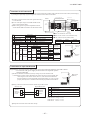
• This appliance must be connected to main power supply by means
of a circuit breaker or switch (fuse:16A) with a contact separation of
at least 3mm.
• When plugging this appliance, a plug conforming to the norm
IEC60884-1 must be used.
• Use the prescribed cables for electrical connection, tighten the
cables securely in terminal block and relieve the cables correctly to
prevent overloading the terminal blocks.
Loose connections or cable mountings can cause anomalous heat
production or fire.
• Arrange the wiring in the control box so that it cannot be pushed up
further into the box. Install the service panel correctly.
Incorrect installation may result in overheating and fire.
• Be sure to switch off the power supply in the event of installation,
inspection or servicing.
If the power supply is not shut off, there is a risk of electric shocks, unit
failure or personal injury due to the unexpected start of fan.
• Be sure to wear protective goggles and gloves while at work.
• Earth leakage breaker must be installed.
If the earth leakage breaker is not installed, it can cause electric shocks.
• Installation must be carried out by the qualified installer.
If you install the system by yourself, it may cause serious trouble such as
water leaks, electric shocks, fire and personal injury, as a result of a system
malfunction. Do not carry out the installation and maintenance work except
the by qualified installer.
• Install the system in full accordance with the installation manual.
Incorrect installation may cause bursts, personal injury, water leaks, electric
shocks and fire.
• Be sure to use only for household and residence.
If this appliance is installed in inferior environment such as machine shop
and etc., it can cause malfunction.
• Use the original accessories and the specified components for
installation.
If parts other than those prescribed by us are used, It may cause water
leaks, electric shocks, fire and personal injury.
• Install the unit in a location with good support.
Unsuitable installation locations can cause the unit to fall and cause
material damage and personal injury.
• Ventilate the working area well in the event of refrigerant leakage
during installation.
If the refrigerant comes into contact with naked flames, poisonous gas is
produced.
• When installing in small rooms, take prevention measures not to
exceed the density limit of refrigerant in the event of leakage,
referred by the formula (accordance with ISO5149).
If the density of refrigerant exceeds the limit, please consult the dealer and
install the ventilation system, otherwise lack of oxygen can occur, which
can cause serious accident.
• After completed installation, check that no refrigerant leaks from
the system.
If refrigerant leaks into the room and comes into contact with an oven or
other hot surface, poisonous gas is produced.
• Use the prescribed pipes, flare nuts and tools for R410A.
Using existing parts (for R22 or R407C) can cause the unit failure and
serious accidents due to burst of the refrigerant circuit.
Always do it according to the
instruction.
• Keep the installation manual together with owner’s manual at a place where
any user can read at any time. Moreover if necessary, ask to hand them to a
new user.
• For installing qualified personnel, take precautions in respect to themselves by
using suitable protective clothing, groves, etc., and then perform the
installation works.
• Please pay attention not to fall down the tools, etc. when installing the unit at
the high position.
• If unusual noise can be heard during operation, consult the dealer.
• The meanings of “Marks” used here are shown as follows:
WARNING
• Read the “SAFETY PRECAUTIONS” carefully first of all and strictly follow it
during the installation work in order to protect yourself.
• The precautionary items mentioned below are distinguished into two levels,
WARNING and
CAUTION .
WARNING : Wrong installation would cause serious consequences such
as injuries or death.
CAUTION : Wrong installation might cause serious consequences
depending on circumstances.
Both mentions the important items to protect your health and safety so strictly
follow them by any means.
• Be sure to confirm no anomaly on the equipment by commissioning after completed installation and explain the operating methods as well as the maintenance
methods of this equipment to the user according to the owner’s manual.
SAFETY PRECAUTIONS
• This installation manual illustrates the method of installing an indoor
unit.
• For electrical wiring work, please see instructions set out on the
backside.
• For outdoor unit installation and refrigerant piping, please refer to page 27.
INSTALLATION MANUAL FOR INDOOR UNIT
(1) Installation of indoor unit
R410A REFRIGERANT USED
Models SRK20ZM-S, 25ZM-S, 35ZM-S, 50ZM-S
WALL TYPE AIR CONDITIONER
8. APPLICATION DATA
'13 • SRK-T-143D
24 -
2
2
2
1
Battery [R03 (AAA, Micro) 1.5V]
Air-cleaning filters
Filter holders
(Attached to the front panel of indoor unit)
Insulation (#486 50 x 100 t3)
5
6
7
8
9
1
Piping cover
(for insulation of connection piping)
Knife
Saw
Tape measure
Hammer
Spanner wrench
Torque wrench
Hole core drill (65mm in diameter)
Wrench key (Hexagon) [4m/m]
2
3
4
5
6
7
8
9
Gas leak detector
Gauge for projection adjustment
Used when flare is made by using
conventional flare tool
Pipe bender
11
12
13
(
Flaring tool set
10
)
Designed specifically
for R410A
(
)
specifically
( Designed
)
for R410A
~ 61.0N·m
( 14.0
(1.4 ~ 6.1kgf·m) )
Plus headed driver
1
Necessary tools for the installation work
1
Drain hose (extension hose)
1
Inclination plate
1
1
Sleeve
Putty
1
Q’ty
Sealing plate
Option parts
5
Wood screws
(for remote control holder ø3.5 X 16mm)
2
1
Remote control holder
Tapping screws
(for installation board ø4 X 25mm)
1
1
4
Wireless remote control
2
Q’ty
3
Installation board
(Attached to the rear of the indoor unit)
1
Standard accessories (Installation kit)
Accessories for indoor unit
○ Before installation check that the power supply matches the air conditioner.
Mounting
board
Bolt
(M6 12)
Mounting
board
Max.10
Nut
(M6)
Fixing on concrete wall
Use of nut anchor
Use of bolt anchor
Outdoor side
5
○ Tape only the portion
that goes through the
wall.
○ Always tape the wiring
with the piping.
Sufficient care must be taken not to damage
the panel when connecting pipes.
○ Hold the bottom of the
piping and fix direction
before stretching it and
shaping it.
Drain hose
Pipings
Taping of the exterior
In case of piping in the right rear direction
Shaping of pipings
Thickness of the wall + 1.5cm
Indoor side
b
Turn to
tighten
Outdoor side
a
c
Installed state
Wood screws
Remote control holder
Right-hand-side piping
Piping in the right direction
Piping in the right rear direction
Left
Left downward
Left
Downward rear
Rear
Right
Piping is possible in the rear, left, left rear, left downward, right or downward direction.
Piping in the left direction
Piping in the left rear direction
Left-hand-side piping
Sleeve
(sold separately)
50
Piping hole (ø65)
4. Connect the drain hose.
○ Remove it with hand or pliers.
2. Remove the drain cap.
(Unit : mm)
○ Insert the drain cap which was removed ○ Insert the drain hose securely, making
at procedure “2” securely using a
rotate. And install the screw.
hexagonal wrench etc.
Note: Be careful that If it is not inserted
Note: Be careful that If it is not inserted
securely, water leakage may
securely, water leakage may occur.
occur.
3. Insert the drain cap.
○ Remove the screw and drain hose,
making it rotate.
1. Remove the drain hose
Piping hole (ø65)
55
Piping for Gas 403.6
Piping for Liquid 471.6
Drain hose (ø16) 531.8
Piping for Liquid Model SRK20∼50, DXK09∼18 : ø6.35
Piping for Gas Model SRK20∼35, DXK09 / 12 : ø9.52
Model SRK50, DXK18
: ø12.7
55
Indoor unit Installation board
Space for service
Space for service 100
139
450
209
106.5
585
106.5
INSTALLATION SPACE (INDOOR UNIT) (FRONT VIEW)
• Matters of special notice when piping from left or central/rear of the unit.
[Top view]
[Drain hose changing procedures]
○ In case of rear piping draw out, cut off the lower
and the right side portions of the sleeve collar.
Installing the support of piping
○ Drill a hole with whole core drill.
Indoor side
ø65
b Top
putty
Outdoor side
Wireless remote control
putty
Indoor side
Installation board
10 cm m
inim
from the um
wall
6.5 cm minimum from the ceiling
Relation between setting plate and indoor unit
Completely seal the hole on
the wall with putty. Otherwise,
furniture, or other, may be
wetted by leaked water or
dewing.
CAUTION
5 cm m
inim
from the um
wall
When drilling the wall that contains a metal lath, wire lath or metal plate, be sure to use pipe hole sleeve sold separately.
Drilling of holes and fixture of sleeve (Option parts)
level by turning the board
with the standard hole as
the center.
Standard
hole
be conducted with four screws in a temporary tightened state.
○ Adjust so the board will be
○ Adjustment of the installation board in the horizontal direction is to
Mating mark for
level surface
Level position (2 locations)
450
Look for the inside wall structures (Intermediats support or pillar
and firmly install the unit after level surface has been checked.)
Installation of installation board
INSTALLATION OF INDOOR UNIT
○ A place where the air conditioner can be received the signal surely during operating the wireless remote control.
○ Places where there is no affected by the TV and radio etc.
○ Do not place where exposed to direct sunlight or near heat devices such as a stove.
Wireless remote control
○ Where there is no obstructions to the air flow and where the cooled and heated air can be evenly distributed.
○ A solid place where the unit or the wall will not vibrate.
○ A place where there will be enough space for servicing. (Where space mentioned below can be secured)
○ Where wiring and the piping work will be easy to conduct.
○ The place where receiving part is not exposed to the direct rays of the sun or the strong rays of the street lighting.
○ A place where it can be easily drained.
○ A place separated at least 1m away from the television or the radio. (To prevent interference to images and sounds.)
○ Places where this unit is not affected by the high frequency equipment or electric equipment.
○ Avoid installing this unit in place where there is much oil mist.
○ Places where there is no electric equipment or household under the installing unit.
Indoor unit
(Install at location that meets the following conditions, after getting approval from the customer)
SELECTION OF INSTALLATION LOCATION
• Do not touch any refrigerant pipes with your hands when the
system is in operation.
During operation the refrigerant pipes become extremely hot or extremely
cold depending the operating condition, and it can cause burn injury or
frost injury.
48.9
47
BEFORE INSTALLATION
• Locations where an equipment affected by high harmonics is placed (TV
set or radio receiver is placed within 1m).
• Locations where drainage cannot run off safely.
It can affect performance or function and etc.
• Do not install the unit near the location where leakage of
combustible gases can occur.
65 Space
for service
47
insulation and over-current etc.
• Do not bundling, winding or processing for the power cord. Or, do
not deforming the power plug due to tread it.
This may cause fire or heating.
7.7
279.1
7.2
-
15 Space
for service
seriously affect the user’s health and safety. This can also cause the
corrosion of the indoor unit and a resultant unit failure or refrigerant leak.
• Ensure that no air enters in the refrigerant circuit when the unit is
installed and removed.
If air enters in the refrigerant circuit, the pressure in the refrigerant circuit
becomes too high, which can cause burst and personal injury.
'13 • SRK-T-143D
Wall
Installation board
Indoor unit
2 Gently push the lower
part to secure the unit.
1 Pass the pipe through
the hole in the wall,
and hook the upper
part of the indoor unit
to the installation board.
Installation Steps
-
Press
Remove
25 -
0.0 - 0.5
0.0 - 0.5
0.0 - 0.5
ø6.35
ø9.52
ø12.7
1.0 - 1.5
1.0 - 1.5
2.0 - 2.5
1.5 - 2.0
Conventional (R22) flare tool
Clutch type
Wing nut type
1.0 - 1.5
1.5 - 2.0
Measurement B (mm)
Mounting of connecting wires
Preparation of indoor unit
In case of faulty wiring connection, the indoor unit stops, and then
the run lamp turns on and the timer lamp blinks.
ELECTRICAL WIRING WORK
Terminal block
The screws of the lid and the terminal
cover are tightened securely.
○ Fitting
1 Do remove the air filter.
2 Cover the body with the front panel.
3 Fit the 3 latches in the upper section.
4 Tighten the 2 set screws.
5 Fit the air filter.
6 Fit the air inlet panel.
Terminal
cover
Lid
How to remove and fit the front panel
CAUTION
CAUTION
Do not apply excess torque to the flared nuts.
Otherwise, the flared nuts may check depending.
○ Removing
1 Remove the air inlet panel.
2 Remove the 2 set screws.
3 Remove the 3 latches in the upper section.
4 Move the lower part of the panel forward and
push upwards to remove.
Use a flare tool designed for R410A or a conventional flare tool.
Please note that measurement B (protrusion from the flaring block) will vary depending on the
type of a flare tool in use.
If a conventional flare tool is used, please use a copper pipe gauge or a similar instrument to
check protrusion so that you can keep measurement B to a correct value.
Clutch type flare tool for
R410A
Copper pipe diameter
○ Connect the pipes on both liquid and gas sides.
○ Tighten the nuts to the following torque.
Liquid side (ø6.35) : 14.0 - 18.0 N·m (1.4 - 1.8 kgf·m)
Gas side (ø9.52) : 34.0 - 42.0 N·m (3.4 - 4.2 kgf·m)
(ø12.7) : 49.0 - 61.0 N·m (4.9 - 6.1 kgf·m)
Open/close and detachment/attachment of the air inlet panel
Copper pipe
Measurement B
Do not apply refrigerating machine
oil to the flared surface.
(Do not turn)
Liquid side
Gas side
The drain hose
tip is in water.
Wav y
The gap to the ground is
5 cm or less.
The drain hose
tip is in the gutter.
Odor from
the gutter
Otherwise water leak may occur.
Cover the exterior portion with outer tape and
shape the piping so it will match the contours
of the route that the piping to take.
Also fix the wiring and pipings to the wall with
clamps.
1. Open the air inlet panel and remove the air filters.
2. Install the air-cleaning filter in the filter holders, and then install the filter holders in the air conditioner.
• Each air-cleaning filter can be installed in the left or right filter holder.
3. Install the air filters and close the inlet panel.
Installing the air-cleaning filters
Set screws
Connection wiring,
Earth wiring
Outer tape
Drain hose
Wood screw
Clamp
Refrigerant piping
Finishing work and fixing
• Cover the indoor unit s flare-connected joints, after they are checked for a gas leak, with an indoor unit
heat insulating material and then wrap them with a tape with an attached insulation pad placed over
the heat insulating material’s slit area.
Position it so that the slit area faces upward.
Use an attached insulation pad for heat insulation.
Cover the coupling with insulator and then cover it with tapes.
Insulation of the connection portion
Vinyl tape
Wall
CAUTION Go through all installation steps and check if the drainage is all right.
Pipe accommodating section
Gutter
○ Pour water to the drain pan located under the heat exchanger, and ensure that the water is discharged outdoor.
○ When the extended drain hose is indoor, securely insulate it with a heat insulator available in the market.
Higher than specified
○ Arrange the drain hose in a downward angle.
○ Avoid the following drain piping.
Drainage
Since this air conditioner has been designed to collect dew drops on the rear
surface to the drain pan, do not attach the power cord above the gutter.
○ To open, pull the panel at both ends of lower part
and release latches, then pull up the panel until
you feel resistance.
(The panel stops at approx. 60o open position)
○ To close, hold the panel at both ends of lower
part to lower downward and push it slightly until
the latch works.
○ To remove, pull up the panel to the position
shown in right illustration and pull it toward you.
○ To install, insert the panel arm into the slot on the
front panel from the position shown in right
illustration, hold the panel at both ends of lower
part, lower it downward slowly, then push it
slightly until the latch works.
block
Flaring
• Flaring work
○ Install the removed flared nuts to the pipes to be connected,
then flared the pipes.
A
CAUTION
Indoor
Connection
The marked portion of the indoor unit base lower latch.
1 Push up at the marked portion of the indoor unit base lower latch, and slightly pull it toward
you. (both right and left hand sides) (The indoor unit base lower latch can be removed from
the installation board)
2 Push up the indoor unit upward. So the indoor unit will be removed from the installation board.
• How to remove the indoor unit from the installation board
Dimension A
Liquid side ø6.35 : 9.1 (mm)
Gas side ø9.52 : 13.2 (mm)
ø12.7 : 16.6 (mm)
Keep the openings of the pipes covered with tapes etc. to prevent dust, sand, etc. from entering them.
○ Remove the flared nuts. (on both liquid and gas sides)
(Do not turn)
Indoor
Preparation
CONNECTION OF REFRIGERANT PIPINGS
Indoor unit base latch
Installation board
Latch (2 locations)
Fixing of indoor unit
90 p 0.5˚
RLA012A020
'13 • SRK-T-143D
H05RNR4G1.5 (example) or 245IEC57
H Harmonized cable type
05 300/500 volts
R Natural-and/or synth, rubber wire insulation
N Polychloroprene rubber conductors insulation
R Stranded core
4or5 Number of conductors
G One conductor of the cable is the earth conductor
(yellow/green)
1.5 Section of copper wire (mm2)
Use cables for interconnection wiring to avoid loosening of the wires.
CENELEC code for cables Required field cables.
In case of faulty wiring connection, the indoor unit stops, and then
the run lamp turns on and the timer lamp blinks.
CAUTION
Mounting method of battery
-
26 -
Cover
Fixing to pillar or wall
5 Wood screws
ø3.5 X 16
2 Wireless remote control
○ Conventionally, operate the wireless remote control by holding
in your hand.
○ Avoid installing it on a clay wall etc.
The power supply voltage is correct as the rating.
No gas leaks from the joints of the service valve.
Power cables and crossover wires are securely fixed to the terminal board.
The screw of the lid and the terminal cover are tightened securely.
After installation
1 2N 3
Clamp
Terminal block
Installing the air-cleaning filters
Air-cleaning filter
Service valve is fully open.
The pipe joints for indoor and outdoor pipes have been insulated.
Filter holder
1. Open the air inlet panel and remove the air filters.
2. Install the air-cleaning filter in the filter holders, and then install the filter holders in the air conditioner.
• Each air-cleaning filter can be installed in the left or right filter holder.
3. Install the air filters and close the inlet panel.
to the procedure described on the left side at the indoor
unit and send a signal by pressing the AC L switch on the
wireless remote control.
Since the signal is sent in about 6 seconds after the
ACL switch is pressed, point the wireless remote control at the
indoor unit for some time.
3 Check that the reception buzzer sound "pip" is emitted from the
indoor unit.
At completion of the setting, the indoor unit emits a buzzer sound
"pip". (If no reception tone is emitted, start the setting from the
beginning again.)
1 Turn off the power supply, and turn it on after 1 minute.
2 Point the wireless remote control that was set according
Setting an indoor unit
TIM
ES
E TU
P
AC
L
pip
Reception
In connecting an interface, connect to the respective terminal securely with the connection harness
supplied with an optional “Interface connection kit SC-BIKN-E” and fasten the connection harness
onto the indoor control box with the clamp supplied with the kit.
For more details, please refer to the user’s manual of your “Interface connection kit SC-BIKN-E”.
1 Remove the front panel and lid of control.
2 Remove the control.
3 There is a terminal (respectively marked with CNS) for the indoor control board.
Air conditioning operation is normal.
No abnormal noise.
Water drains smoothly.
Protective functions are not working.
Test run
The wireless remote control is normal.
Operation of the unit has been explained to the customer. (Three-minutes restart preventive timer)
When the air conditioner is restarted or when changing the operation, the unit will not start operating for
approximately 3 minutes. This is to protect the unit and it is not a malfunction.
CNS terminal
Lid of control
Indoor unit PCB
CONCERNING TERMINAL CONNECTION FOR AN INTERFACE
3 Insert batteries. Close the cover.
Disconnect
switching line next
to the battery with
wire cutters.
1 Pull out the cover and take out batteries.
2 Disconnect the
Setting the wireless remote control
When two air conditioners are installed in the same room, use this setting when the two air conditioners are not operated with one wireless remote control. Set the
wireless remote control and indoor unit.
INSTALLING TWO AIR CONDITIONERS IN THE SAME ROOM
Terminal
cover
Lid
Set screws
Check the following points again after completion of the installation, and before turning on the power. Conduct a test run again and ensure that the unit operates properly.
At the same time, explain to the customer how to use the unit and how to take care of the unit following the user’s manual.
Unit ON/OFF button
• Forced cooling operation
Turn on a power supply again after a while after turn off a power supply.
Then press continually the ON/OFF button 5 seconds or more.
INSTALLATION TEST CHECK POINTS
<How to pump down>
1 Connect charge hose to check joint of outdoor unit.
2 Liquid side : Close the liquid valve with hexagon wrench key.
Gas side : Fully open the gas valve.
Carry out cooling operation. (If indoor temperature is low, operate
forced cooling operation.)
3 After low pressure gauge become 0.01MPa, stop cooling operation
and close the gas valve.
○ In order to protect the environment, be sure to pump down (recovery of refrigerant).
○ Pump down is the method of recovering refrigerant from the indoor unit to the
outdoor unit when the pipes are removed from the unit.
HOW TO RELOCATE OR DISPOSE OF THE UNIT
Do not use new and
old batteries together.
CAUTION
6 Battery
○ Uncover the wireless remote control, and mount the batteries [R03 (AAA, Micro),
×2 pieces] in the body regularly.
(Fit the poles with the indication marks, + & − without fail)
Do remove the air filter.
Cover the body with the front panel.
Fit the 3 latches in the upper section.
Tighten the 2 set screws.
Fit the air filter.
Fit the air inlet panel.
The screws of the lid and the terminal
cover are tightened securely.
1
2
3
4
5
6
• Earth wire shall be Yellow/Green (Y/G) in color and longer than other AC wires for safety reason.
INSTALLATION OF WIRELESS REMOTE CONTROL
Remove the lid.
Remove the terminal cover.
Remove the wiring clamp.
Connect the connecting wire securely to the terminal block.
1) Connect the connection wire securely to the terminal
block. If the wire is not affixed completely, contact will be
poor, and it is dangerous as the terminal block may heat
up and catch fire.
2) Take care not to confuse the terminal numbers for indoor
and outdoor connections.
5 Fix the connecting wire by wiring clamp.
6 Attach the terminal cover.
7 Attach the lid.
1
2
3
4
Mounting of connecting wires
Preparation of indoor unit
ELECTRICAL WIRING WORK
shown in right illustration and pull it toward you.
○ To install, insert the panel arm into the slot on the
front panel from the position shown in right
illustration, hold the panel at both ends of lower
part, lower it downward slowly, then push it
slightly until the latch works.
'13 • SRK-T-143D
INSTALLATION MANUAL FOR OUTDOOR UNIT
SRC20·25·35·50
Model DXC09·12·18
R410A REFRIGERANT USED
-
27 -
• Ventilate the working area well in the event of refrigerant leakage during
installation.
If the refrigerant comes into contact with naked flames, poisonous gas is produced.
• Use the prescribed pipes, flare nuts and tools for R410A.
Using existing parts (for R22 or R407C) can cause the unit failure and serious
accidents due to burst of the refrigerant circuit.
• Tighten the flare nut by torque wrench with specified method.
If the flare nut were tightened with excess torque, this may cause burst and
refrigerant leakage after a long period.
• Do not open the service valves for liquid line and gas line until
completed refrigerant piping work, air tightness test and evacuation.
If the compressor is operated in state of opening service valves before
completed connection of refrigerant piping work, air can be sucked into refrigerant
circuit, which can cause bust or personal injury due to anomalously high pressure
in the refrigerant.
• The electrical installation must be carried out by the qualified electrician
in accordance with “the norm for electrical work” and “national wiring
regulation”, and the system must be connected to the dedicated circuit.
Power supply with insufficient capacity and incorrect function done by improper
work can cause electric shocks and fire.
• Be sure to shut off the power before starting electrical work.
Failure to shut off the power can cause electric shocks, unit failure or incorrect
function of equipment.
• Be sure to use the cables conformed to safety standard and cable
ampacity for power distribution work.
Unconformable cables can cause electric leak, anomalous heat production or fire.
• This appliance must be connected to main power supply by means of a
• Do not perform any change of protective device itself or its setup
condition.
The forced operation by short-circuiting protective device of pressure switch and
temperature controller or the use of non specified component can cause fire or
burst.
•
•
•
•
•
•
•
•
• Use the circuit breaker for all pole correct capacity. Circuit breaker
should be the one that disconnect all poles under over current.
Using the incorrect circuit breaker, it can cause the unit malfunction and fire.
• Install isolator or disconnect switch on the power supply wiring in
accordance with the local codes and regulations.
• Take care when carrying the unit by hand.
If the unit weights more than 20kg, it must be carried by two or more persons. Do
not carry by the plastic straps, always use the carry handle when carrying the unit
by hand. Use gloves to minimize the risk of cuts by the aluminum fins.
• Dispose of any packing materials correctly.
Always do it according to the instruction.
circuit breaker or switch (fuse:16A) with a contact separation of at least
3mm.
Arrange the wiring in the control box so that it cannot be pushed up
further into the box. Install the service panel correctly.
Incorrect installation may result in overheating and fire.
Use the prescribed cables for electrical connection, tighten the cables
securely in terminal block and relieve the cables correctly to prevent
overloading the terminal blocks.
Loose connections or cable mountings can cause anomalous heat production or fire.
Be sure to fix up the service panels.
Incorrect fixing can cause electric shocks or fire due to intrusion of dust or water.
Be sure to switch off the power supply in the event of installation,
inspection or servicing.
If the power supply is not shut off, there is a risk of electric shocks, unit failure or
personal injury due to the unexpected start of fan.
Stop the compressor before removing the pipe after shutting the
service valve on pump down work.
If the pipe is removed when the compressor is in operation with the service valve
open, air would be mixed in the refrigeration circuit and it could cause explosion
and injuries due to abnormal high pressure in the cooling cycle.
Only use prescribed optional parts. The installation must be carried out
by the qualified installer.
If you install the system by yourself, it can cause serious trouble such as water
leaks, electric shocks, fire.
Be sure to wear protective goggles and gloves while at work.
Earth leakage breaker must be installed.
If the earth leakage breaker is not installed, it can cause electric shocks.
• When perform the air conditioner operation (cooling or drying operation)
in which ventilator is installed in the room. In this case, using the air
conditioner in parallel with the ventilator, there is the possibility that
drain water may backflow in accordance with the room lapse into the
negative pressure status. Therefore, set up the opening port such as
• Carry out the electrical work for ground lead with care.
Do not connect the ground lead to the gas line, water line, lightning conductor or telephone line’s ground lead. Incorrect grounding can cause unit faults such as electric shocks due to short-circuiting.
CAUTION
• Do not bundling, winding or processing for the power cord. Or, do not
• Ensure that no air enters in the refrigerant circuit when the unit is
deforming the power plug due to tread it.
installed and removed.
This may cause fire or heating.
If air enters in the refrigerant circuit, the pressure in the refrigerant circuit
• Do not run the unit with removed panels or protections.
becomes too high, which can cause burst and personal injury.
• Do not processing, splice the power cord, or share a socket with other power plugs. Touching rotating equipments, hot surfaces or high voltage parts can cause
This may cause fire or electric shock due to defecting contact, defecting insulation
personal injury due to entrapment, burn or electric shocks.
and over-current etc.
• Installation must be carried out by the qualified installer.
If you install the system by yourself, it may cause serious trouble such as water leaks,
electric shocks, fire and personal injury, as a result of a system malfunction. Do not
carry out the installation and maintenance work except the by qualified installer.
• Install the system in full accordance with the installation manual.
Incorrect installation may cause bursts, personal injury, water leaks, electric
shocks and fire.
• Be sure to use only for household and residence.
If this appliance is installed in inferior environment such as machine shop and etc.,
it can cause malfunction.
• When installing in small rooms, take prevention measures not to
exceed the density limit of refrigerant in the event of leakage, referred
by the formula (accordance with ISO5149).
If the density of refrigerant exceeds the limit, please consult the dealer and install
the ventilation system, otherwise lack of oxygen can occur, which can cause serious
accident.
• Use the original accessories and the specified components for
installation.
If parts other than those prescribed by us are used, It may cause water leaks,
electric shocks, fire and personal injury.
• Install the unit in a location with good support.
Unsuitable installation locations can cause the unit to fall and cause material
damage and personal injury.
• Ensure the unit is stable when installed, so that it can withstand
earthquakes and strong winds.
Unsuitable installation locations can cause the unit to fall and cause material
damage and personal injury.
Never do it under any circumstances.
• Keep the installation manual together with owner’s manual at a place where any user can read at any time.
Moreover if necessary, ask to hand them to a new user.
• For installing qualified personnel, take precautions in respect to themselves by using suitable protective
clothing, groves, etc., and then perform the installation works.
• Please pay attention not to fall down the tools, etc. when installing the unit at the high position.
• If unusual noise can be heard during operation, consult the dealer.
• The meanings of “Marks” used here are shown as follows:
WARNING
• Read the “SAFETY PRECAUTIONS” carefully first of all and strictly follow it during the installation work in order
to protect yourself.
• The precautionary items mentioned below are distinguished into two levels,
WARNING and
CAUTION .
WARNING : Wrong installation would cause serious consequences such as injuries or death.
CAUTION : Wrong installation might cause serious consequences depending on circumstances.
Both mentions the important items to protect your health and safety so strictly follow them by any means.
• Be sure to confirm no anomaly on the equipment by commissioning after completed installation and explain the
operating methods as well as the maintenance methods of this equipment to the user according to the owner’s
manual.
SAFETY PRECAUTIONS
• This installation manual deals with outdoor units and general installation specifications only. For indoor units, refer to page 23.
• When install the unit, be sure to check whether the selection of installation place, power supply specifications, usage limitation (piping length, height differences between indoor and outdoor units, power
supply voltage and etc.) and installation spaces.
Models SRC20ZM-S, 25ZM-S, 35ZM-S, 50ZM-S
(2) Installation of outdoor unit
RWC012A037
'13 • SRK-T-143D
1.
(
4)
•
•
B
•
•
•
•
•
•
•
•
•
•
3)
•
2)
•
•
1)
• Do
Ac
• Au
The
Acc
• Do
• In
• All
Not
-
n.
protective
d at any time.
r units, power
25·35·50
12·18
ANT USED
012A037
28 -
The forced operation by short-circuiting protective device of pressure switch and
temperature controller or the use of non specified component can cause fire or
burst.
4
1
Q’ty
Sealing plate
Sleeve
Inclination plate
Putty
Drain hose (extension hose)
Piping cover
f
(for insulation of connection piping)
a
b
c
d
e
Option parts
2 Drain elbow (Heat pump type only)
1
1
1
1
1
1
1
Q’ty
1
2
3
4
5
6
7
8
Plus headed driver
Knife
Saw
Tape measure
Hammer
Spanner wrench
Torque wrench [14.0~62.0N·m (1.4~6.2kgf·m)]
Hole core drill (65mm in diameter)
Necessary tools for the installation work
9 Wrench key (Hexagon) [4m/m]
10 Vacuum pump
Vacuum pump adapter (Anti-reverse flow type)
11
(Designed specifically for R410A)
12 Gauge manifold (Designed specifically for R410A)
13 Charge hose (Designed specifically for R410A)
14 Flaring tool set (Designed specifically for R410A)
15 Gas leak detector (Designed specifically for R410A)
Gauge for projection adjustment
16
(Used when flare is made by using conventional flare tool)
CAUTION
(Take particular care in carrying in or moving the unit, and always perform such an operation with two or more persons.)
When a unit is hoisted with slings for haulage, take into consideration the offset of its gravity center position.
1. HAULAGE AND INSTALLATION
• Do not use any refrigerant other than R410A. R410A will rise to pressure about 1.6 times higher than that of a conventional refrigerant.
A cylinder containing R410A has a pink indication mark on the top.
• A unit designed for R410A has adopted a different size indoor unit service valve charge port and a different size check joi nt provided in the unit to prevent the charging of a wrong refrigerant by mistake.
The processed dimension of the flared part of a refrigerant pipe and a flare nut’s parallel side measurement have also been altered to raise strength against pressure.
Accordingly, you are required to arrange dedicated R410A tools listed in the table on the left before installing or servicing this unit.
• Do not use a charge cylinder. The use of a charge cylinder will cause the refrigerant composition to change, which results in performance degradation.
• In charging refrigerant, always take it out from a cylinder in the liquid phase.
• All indoor units must be models designed exclusively for R410A. Check connectable indoor unit models in a catalog, etc. (A wrong indoor unit, if connected into the system, will impair proper system operation)
Notabilia as a unit designed for R410A
Grommet
SRC20~35
Model
1 (Heat pump
DXC09,12
type only) Model SRC50/DXC18
Accessories for outdoor unit
• Model name and power source
• Refrigerant piping length
• Piping, wiring and miscellaneous small parts
• Indoor unit installation manual
Check before installation work
• Do not install the outdoor unit in a location where insects and small
animals can inhabit.
Insects and small animals can enter the electric parts and cause damage or fire.
Instruct the user to keep the surroundings clean.
• Do not use the base flame for outdoor unit which is corroded or damaged
due to long periods of operation.
Using an old and damage base flame can cause the unit falling down and cause
personal injury.
• Do not use any materials other than a fuse with the correct rating in the
location where fuses are to be used.
Connecting the circuit with copper wire or other metal thread can cause unit
failure and fire.
• Do not touch any buttons with wet hands.
It can cause electric shocks.
• Do not touch any refrigerant pipes with your hands when the system is in
operation.
During operation the refrigerant pipes become extremely hot or extremely cold
depending the operating condition, and it can cause burn injury or frost injury.
• Do not touch the suction or aluminum fin on the outdoor unit.
This may cause injury.
• Do not put anything on the outdoor unit and operating unit.
This may cause damage the objects or injury due to falling to the object.
• Do not use the unit for special purposes such as storing foods, cooling
precision instruments and preservation of animals, plants or art.
• Do not clean up the unit with water.
• Do not install the unit in the locations listed below.
• Locations where carbon fiber, metal powder or any powder is floating.
• Locations where any substances that can affect the unit such as sulphide gas,
chloride gas, acid and alkaline can occur.
• Vehicles and ships.
• Locations where cosmetic or special sprays are often used.
• Locations with direct exposure of oil mist and steam such as kitchen and
machine plant.
• Locations where any machines which generate high frequency harmonics are
used.
• Locations with salty atmospheres such as coastlines.
• Locations with heavy snow (If installed, be sure to provide base flame and snow
hood mentioned in the manual).
• Locations where the unit is exposed to chimney smoke.
• Locations at high altitude (more than 1000m high).
• Locations with ammonic atmospheres.
• Locations where heat radiation from other heat source can affect the unit.
• Locations without good air circulation.
• Locations with any obstacles which can prevent inlet and outlet air of the unit.
• Locations where short circuit of air can occur (in case of multiple units
installation).
• Locations where strong air blows against the air outlet of outdoor unit.
• Locations where something located above the unit could fall.
It can cause remarkable decrease in performance, corrosion and damage of
components, malfunction and fire.
• Do not install the outdoor unit in the locations listed below.
• Locations where discharged hot air or operating sound of the outdoor unit can
bother neighborhood.
• Locations where outlet air of the outdoor unit blows directly to an animal or
plants. The outlet air can affect adversely to the plant etc.
• Locations where vibration can be amplified and transmitted due to insufficient
strength of structure.
• Locations where vibration and operation sound generated by the outdoor unit
can affect seriously (on the wall or at the place near bed room).
• Locations where an equipment affected by high harmonics is placed (TV set or
radio receiver is placed within 1m).
• Locations where drainage cannot run off safely.
It can affect surrounding environment and cause a claim.
• Do not install the unit near the location where leakage of combustible
gases can occur.
If leaked gases accumulate around the unit, it can cause fire.
• Do not install the unit where corrosive gas (such as sulfurous acid gas etc.)
or combustible gas (such as thinner and petroleum gases) can accumulate
or collect, or where volatile combustible substances are handled.
Corrosive gas can cause corrosion of heat exchanger, breakage of plastic parts
and etc. And combustible gas can cause fire.
• Do not install nor use the system close to the equipment that generates
electromagnetic fields or high frequency harmonics.
Equipment such as inverters, standby generators, medical high frequency
equipments and telecommunication equipments can affect the system, and cause
malfunctions and breakdowns. The system can also affect medical equipment and
telecommunication equipment, and obstruct its function or cause jamming.
• When perform the air conditioner operation (cooling or drying operation)
in which ventilator is installed in the room. In this case, using the air
conditioner in parallel with the ventilator, there is the possibility that
drain water may backflow in accordance with the room lapse into the
negative pressure status. Therefore, set up the opening port such as
incorporate the air into the room that may appropriate to ventilation (For
example; Open the door a little). In addition, just as above, so set up the
opening port if the room lapse into negative pressure status due to
register of the wind for the high rise apartment etc.
• Use the circuit breaker for all pole correct capacity. Circuit breaker
• Take care when carrying the unit by hand.
should be the one that disconnect all poles under over current.
If the unit weights more than 20kg, it must be carried by two or more persons. Do
Using the incorrect circuit breaker, it can cause the unit malfunction and fire.
not carry by the plastic straps, always use the carry handle when carrying the unit
• Install isolator or disconnect switch on the power supply wiring in
by hand. Use gloves to minimize the risk of cuts by the aluminum fins.
accordance with the local codes and regulations.
• Dispose of any packing materials correctly.
The isolator should be locked in OFF state in accordance with EN60204-1.
Any remaining packing materials can cause personal injury as it contains nails and
• After maintenance, all wiring, wiring ties and the like, should be returned wood. And to avoid danger of suffocation, be sure to keep the plastic wrapper
to their original state and wiring route, and the necessary clearance from
away from children and to dispose after tear it up.
all metal parts should be secured.
• Be sure to insulate the refrigerant pipes so as not to condense the
• Secure a space for installation, inspection and maintenance specified in
ambient air moisture on them.
the manual.
Insufficient insulation can cause condensation, which can lead to moisture
Insufficient space can result in accident such as personal injury due to falling from
damage on the ceiling, floor, furniture and any other valuables.
the installation place.
• Carry out the electrical work for ground lead with care.
Do not connect the ground lead to the gas line, water line, lightning conductor or telephone line’s ground lead. Incorrect grounding can cause unit faults such as electric shocks due to short-circuiting.
CAUTION
This may cause fire or heating.
If air enters in the refrigerant circuit, the pressure in the refrigerant circuit
• Do not run the unit with removed panels or protections.
becomes too high, which can cause burst and personal injury.
• Do not processing, splice the power cord, or share a socket with other power plugs. Touching rotating equipments, hot surfaces or high voltage parts can cause
This may cause fire or electric shock due to defecting contact, defecting insulation
personal injury due to entrapment, burn or electric shocks.
and over-current etc.
The use restriction
When the
When the
ø9.52
ø9.52
Refrigerant piping (branch pipe L)
Indoor unit connected
ø9.52
Flare
Outdoor unit connected
Gas pip
Model SR
Determine refrigerant pipe size pursuant
the indoor unit specifications.
2) Determination of pipe si
CAUTION
Elevation difference between
indoor and outdoor units
Main pipe len
Restriction
• Check the following points in light of
• Observe the following restrictions on
• Additional refrigerant charge is not re
1) Restrictions on unit inst
2. REFRIGERANT PIP
Since drain water generated by defrost
• Do not execute drain piping work by
[Refer to Drain piping work.]
1 Install the unit on the base so that t
higher than snow cover surface.
(1) If the unit is installed in the area where
The bottom plate of unit and intake, ou
4) Caution about selection of
high pressure and a broken fan.
'13 • SRK-T-143D
us trouble such as water
ation with the service valve
d it could cause explosion
ling cycle.
lation must be carried out
after shutting the
ctric shocks, unit failure or
intrusion of dust or water.
vent of installation,
alous heat production or fire.
cannot be pushed up
orrectly.
.
ction, tighten the cables
les correctly to prevent
tact separation of at least
to the instruction.
l thread can cause unit
h the correct rating in the
it falling down and cause
h is corroded or damaged
nd cause damage or fire.
ere insects and small
oling or drying operation)
his case, using the air
is the possibility that
e room lapse into the
opening port such as
opriate to ventilation (For
st as above, so set up the
ssure status due to
etc.
ice of pressure switch and
ponent can cause fire or
e itself or its setup
e electric shocks.
while at work.
Heavy
2 Install the unit under or provide the roof on site.
• Check the following points in light of the indoor unit specifications and the installation site.
1) Restrictions on unit installation and use
2. REFRIGERANT PIPING WORK
Since drain water generated by defrost control may freeze, following measures are required.
• Do not execute drain piping work by using a drain elbow and drain grommets (accessories).
[Refer to Drain piping work.]
1 Install the unit on the base so that the bottom is
higher than snow cover surface.
(1) If the unit is installed in the area where the snow will accumulate, following measures are required.
The bottom plate of unit and intake, outlet may be blocked by snow.
4) Caution about selection of installation location
Be careful of the following conditions and choose an installation place.
• Where air is not trapped.
• Where the installation fittings can be firmly installed.
• Where wind does not hinder the intake and outlet pipes.
• Out of the heat range of other heat sources.
• A place where stringent regulation of electric noises is applicable.
• Where it is safe for the drain water to be discharged.
• Where noise and hot air will not bother neighboring residents.
• Where snow will not accumulate.
• Where strong winds will not blow against the outlet pipe.
• A place where no TV set or radio receiver is placed within 1m.
(If electrical interference is caused, seek a place less likely to cause the problem)
• If a operation is conducted when the outdoor air temperature is –5°C lower, the outdoor unit should be
installed at a place where it is not influenced by natural wind.
• Where it is likely that the unit is subjected to strong winds, provide wind guards according to the
following guidelines. Strong winds can cause performance degradation, an accidental stop due to a rise of
high pressure and a broken fan.
3) Selecting the installation location
• The right hand side of the unit as viewed from the front (diffuser side) is heavier.
A person carrying the right hand side must take heed of this fact. A person
carrying the left hand side must hold with his right hand the handle provided on
the front panel of the unit and with his left hand the corner column section.
2) Portage
Pad
•
•
•
•
•
Intake
Outlet
510
158.4
100
250
Use a thicker block to anchor deeper.
89
80
Open
280
75
II
80
250
280
Open
III
Intake
L2
Outlet
Intake
510
Outlet
Intake
L3
201
L1
L4
(service
space )
The height of a wall is 1200mm or less.
Open
100
L3
L4
I
(mm)
80
Open
180
Open
IV
Model SRC20~50/DXC09~18
L1
L2
Model SRC50/DXC18
Size
Example installation
Wind
direction
Wind
direction
2 Install so the direction of the air from the
blowing outlet will be perpendicular to the
direction of the wind.
In installing the unit, fix the unit’s legs with bolts specified on the above.
The protrusion of an anchor bolt on the front side must be kept within 15mm.
Securely install the unit so that it does not fall over during earthquakes or strong winds, etc.
Refer to the above illustrations for information regarding concrete foundations.
Install the unit in a level area. (With a gradient of 5mm or less.) Improper installation can result in a
compressor failure, broken piping within the unit and abnormal noise generation.
Use a long block to extend the width.
Fasten with bolts
(M10-12)
2 Notabilia for installation
111.6
Model SRC20~35/DXC09,12
1 Anchor bolt fixed position
6) Installation
• Walls surrounding the unit in the four sides are not
acceptable.
• There must be a 1-meter or larger space in the above.
• When more than one unit are installed side by side,
provide a 250mm or wider interval between them as a
service space. In order to facilitate servicing of
controllers, please provide a sufficient space between
units so that their top plates can be removed easily.
• Where a danger of short-circuiting exists, install guide
louvers.
• When more than one unit are installed, provide sufficient
intake space consciously so that short-circuiting may not
occur.
• Where piling snow can bury the outdoor unit, provide
proper snow guards.
5) Installation space
Over 500mm
1 Place the unit outlet side is turned to the wall.
(2) If the unit can be affected by strong wind, following measures are required.
Strong wind can cause damage of fan (fan motor), or can cause performance degradation, or can trigger
anomalous stop of the unit due to rising of high pressure.
When a unit is hoisted with slings for haulage, take into consideration the offset of its gravity center position.
If not properly balanced, the unit can be thrown off-balance and fall.
• Deliver the unit as close as possible to the installation site before removing it from
the packaging.
• When you have to unpack the unit for a compelling reason before you haul it to
the installation point, hoist the unit with nylon slings or ropes and protection pads
so that you may not damage the unit.
1) Delivery
CAUTION
(Take particular care in carrying in or moving the unit, and always perform such an operation with two or more persons.)
290
position.
1. HAULAGE AND INSTALLATION
290
uitable protective
24.3
can read at any time.
The processed dimension of the flared part of a refrigerant pipe and a flare nut’s parallel side measurement have also been altered to raise strength against pressure.
Accordingly, you are required to arrange dedicated R410A tools listed in the table on the left before installing or servicing this unit.
• Do not use a charge cylinder. The use of a charge cylinder will cause the refrigerant composition to change, which results in performance degradation.
• In charging refrigerant, always take it out from a cylinder in the liquid phase.
• All indoor units must be models designed exclusively for R410A. Check connectable indoor unit models in a catalog, etc. (A wrong indoor unit, if connected into the system, will impair proper system operation)
24.3
312.5
351.6
14.8
29 -
312.5
351.6
-
14.8
outdoor units, power
'13 • SRK-T-143D
apter (Anti-reverse flow type)
cally for R410A)
Designed specifically for R410A)
signed specifically for R410A)
esigned specifically for R410A)
r (Designed specifically for R410A)
ion adjustment
is made by using conventional flare tool)
agon) [4m/m]
oor unit and operating unit.
or injury due to falling to the object.
urposes such as storing foods, cooling
ervation of animals, plants or art.
ater.
s become extremely hot or extremely cold
nd it can cause burn injury or frost injury.
inum fin on the outdoor unit.
es with your hands when the system is in
et hands.
than a fuse with the correct rating in the
used.
ire or other metal thread can cause unit
the electric parts and cause damage or fire.
dings clean.
tdoor unit which is corroded or damaged
.
can cause the unit falling down and cause
10m or less
ø6.35
Flare
ø9.52
Flare
ø9.52
ø9.52
Outdoor unit connected
Refrigerant piping (branch pipe L)
Indoor unit connected
ø12.7
ø12.7
ø12.7
Flare
Gas pipe
ø6.35
ø6.35
ø6.35
Flare
Liquid pipe
Model SRC50/DXC18
Please remove the screw of a side cover and
remove to the front.
O-type pipe
O-type pipe
Pipe material*
Tightening angle (o)
45 ~ 60
30 ~ 45
30 ~ 45
Tightening torque (N·m)
14 ~ 18
34 ~ 42
49 ~ 61
Service valve size (mm)
ø6.35 (1/4")
ø9.52 (3/8")
ø12.7 (1/2")
(mm)
0
–04
9.1
13.2
16.6
A
Nitrogen
gas
Do not hold the valve cap area with a spanner.
ø6.35
ø9.52
ø12.7
(mm)
0 ~ 0.5
1.0 ~ 1.5
In the case of a rigid (clutch) type
With an R410A tool With a conventional tool
L
Outdoor unit
Pre
rize
ssu
Gas side
service valve
Check joint
Indoor unit
Use a torque wrench. If a torque wrench is not
available, fasten the flare nut manually first and then
tighten it further, using the left table as a guide.
Copper pipe
outer diameter
Hand
0.5MPa
Secondary side
Relief valve
Primary side
Station valve
Copper pipe protrusion for flaring : B
ø6.35
ø9.52
ø12.7
Copper pipe
outer diameter
Flared pipe end : A
1 Although outdoor and indoor units themselves have been tested for air tightness at the factory, check the connecting pipes after the installation work for air tightness from the service
valve’s check joint equipped on the outdoor unit side. While conducting a test, keep the service valve shut all the time.
a) Raise the pressure to 0.5MPa, and then stop. Leave it for five minutes to see if the pressure drops.
b) Then raise the pressure to 1.5MPa, and stop. Leave it for five more minutes to see if the pressure drops.
c) Then raise the pressure to the specified level (4.15MPa), and record the ambient temperature and the pressure.
d) If no pressure drop is observed with an installation pressurized to the specified level and left for about one day, it is acceptable. When the ambient temperature fall 1oC, the pressure also
150
200
250
Recommended length of a tool handle (mm)
Fix both liquid and gas service valves at the valve main bodies as illustrated on the right, and then fasten them,
applying appropriate fastening torque.
The screw of the
side cover is
tightened securely.
Side cover
A
Brazing
O-type pipe
0.8
0.8
0.8
*Phosphorus deoxidized seamless copper pipe ICS 23.040.15, ICS 77.150.30
ø12.7
ø9.52
ø6.35
Do not apply force beyond proper fastening torque in tightening the flare nut.
5) Air tightness test
CAUTION
• Carry out the on site piping work with the service valve fully closed.
• Give sufficient protection to a pipe end (compressed and blazed, or with an
adhesive tape) so that water or foreign matters may not enter the piping.
• Bend a pipe to a radius as large as practical (R100 ~ R150). Do not bend a pipe
repeatedly to correct its form.
• Flare connection is used between the unit and refrigerant pipe. Flare a pipe after
engaging a flare nut onto it. Flare dimensions for R410A are different from
those for conventional R407C. Although we recommend the use of flaring tools
designed specifically for R410A, conventional flaring tools can also be used by
adjusting the measurement of protrusion B with a protrusion control gauge.
• The pipe should be anchored every 1.5m or less to isolate the vibration.
• Tighten a flare joint securely.
How to remove the side cover
<N2>
Only use nitrogen gas (N2)
Taping
Pipe diameter [mm]
Take care so that installed pipes may not touch components within a unit.
If touching with an internal component, it will generate abnormal sounds and/or vibrations.
4) On-site piping work
Outdoor unit
Plug the end of the pipe with tape, or other
material, and fill the pipe with nitrogen gas.
H
Minimum pipe wall thickness [mm]
Without nitrogen gas, a large quantity of foreign matters
(oxidized film) are created, causing a critical failure from
capillary tube or expansion valve clogging.
Select pipes having a wall thickness larger than the specified minimum pipe thickness.
IMPORTANT
H
H
L
Brazing must be performed under a nitrogen gas flow.
About brazing
When pipe is brazing.
• Select refrigerant pipes of the table shown on the right wall thickness and material as specified
for each pipe size.
3) Refrigerant pipe wall thickness and material
ø6.35
ø6.35
Liquid pipe
Gas pipe
Model SRC20~35/DXC09,12
Determine refrigerant pipe size pursuant to the following guidelines based on
the indoor unit specifications.
NOTE
15m or less
15m or less
25m or less
Marks appearing in the
drawing on the right
The use restrictions appearing in the table above are applicable to the standard pipe size combinations shown in the table below.
10m or less
When the outdoor unit is positioned lower,
15m or less
Dimensional restrictions
Model SRC20~35/DXC09,12 Model SRC50/DXC18
When the outdoor unit is positioned higher,
2) Determination of pipe size
CAUTION
Elevation difference between
indoor and outdoor units
Main pipe length
Restrictions
Indoor unit
In installing the unit, fix the unit’s legs with bolts specified on the above.
The protrusion of an anchor bolt on the front side must be kept within 15mm.
Securely install the unit so that it does not fall over during earthquakes or strong winds, etc.
Refer to the above illustrations for information regarding concrete foundations.
Install the unit in a level area. (With a gradient of 5mm or less.) Improper installation can result in a
compressor failure, broken piping within the unit and abnormal noise generation.
• Check the following points in light of the indoor unit specifications and the installation site.
• Observe the following restrictions on unit installation and use. Improper installation can result in a compressor failure or performance degradation.
• Additional refrigerant charge is not required at all (Model SRC20~35/DXC09,12).
1) Restrictions on unit installation and use
2. REFRIGERANT PIPING WORK
•
•
•
•
•
Nitrogen
n a location where insects and small
• Do not execute drain piping work by using a drain elbow and drain grommets (accessories).
[Refer to Drain piping work.]
B
30 -
Close
-
•
•
C
P
Electrical installation work must be
Electrical installation work must be
• Do not use any supply cord light
• braided cord (code designation
• ordinary tough rubber sheathe
• flat twin tinsel cord (code desig
Use polychloroprene sheathed fle
• Ground the unit. Do not connect t
If improperly grounded, an electri
• A grounding wire must be conne
• The installation of an impulse wit
such as an electric shock or a fire
• Do not turn on the power until th
• Do not use a condensive capacito
abnormal overheat accident)
• For power supply cables, use con
• Do not lay electronic control cabl
result in the malfunctioning or a f
• Fasten cables so that may not to
• When cables are connected, mak
terminal connection and then atta
penetrates into the box.)
• Never use a shield cable.
• SRC-ZMA-S, SRC-ZMXA-S and D
demand response modes 1, 2, an
the sense of cooling operation or
for DRED input and supports ELV
4. ELECTRICAL
'13 • SRK-T-143D
-
31 -
Tightening angle (o)
45 ~ 60
30 ~ 45
30 ~ 45
Tightening torque (N·m)
14 ~ 18
34 ~ 42
49 ~ 61
Service valve size (mm)
ø6.35 (1/4")
ø9.52 (3/8")
ø12.7 (1/2")
Do not hold the valve cap area with a spanner.
<Work flow>
Fill refrigerant
Vacuum gauge check
Confirm that the vacuum gauge indicator does not rise even if
the system is left for one hour or more.
Vacuuming completed
Run the vacuum pump for at least one hour after the vacuum
gauge shows –0.1MPa or lower. (–76cmHg or lower)
Vacuuming begins
Air tightness test completed
0.02
1.35
Refrigerant volume charged
for shipment at the factory
(kg)
15
Installation’s pipe length (m)
covered without additional
refrigerant charge
Check joint
Service valve cap
Service valve
(Gas side)
Handle Lo
-0.1MPa
(-76cmHg)
Service valve cap
Service valve size
(mm)
ø6.35 (1/4")
ø9.52 (3/8")
ø12.7 (1/2")
• Water may drip where there is a larger amount of drain
water. Seal around the drain elbow and drain
grommets with putty or adequate caulking material.
Model SRC20~35/DXC09,12
Do not put a grommet on
this hole.
This is a supplementary
drain hole to discharge
CAUTION
Model SRC50/DXC18
Insulation
Gas piping
Exterior tape
Pipe cover (procured locally)
• When condensed water needs to be led to a drain, etc., install
the unit on a flat base (supplied separately as an optional part)
or concrete blocks.
Then, please secure space for the drain elbow and the drain
hose.
Liquid piping
Wires for connecting indoor
and outdoor units
Band (procured locally)
NOTE Put down the refrigerant volume calculated from the pipe length onto the caution label attached
on the service panel.
• All gas pipes must be securely heat insulated in order to prevent damage from dripping water that comes from the condensation formed on them during a cooling
operation or personal injury from burns because their surface can reach quite a high temperature due to discharged gas flowing inside during a heating operation.
• Wrap indoor units’ flare joints with heat insulating parts (pipe cover) for heat insulation (both gas and liquid pipes).
• Give heat insulation to both gas and liquid side pipes. Bundle a heat insulating material and a pipe tightly together so that no gaps may be left between them and
wrap them together with a connecting cable by a dressing tape.
• Both gas and liquid pipes need to be dressed with 20mm or thicker heat insulation materials above the ceiling where relative humidity exceeds 70%.
• Execute drain piping by using a drain elbow and drain
grommets supplied separately as accessories, where
water drained from the outdoor unit is a problem.
10 ~ 12
Check joint blind nut
tightening torque (N·m)
Indoor unit
• Since R410A refrigerant must be charged in the liquid phase, you should charge it, keeping the container
cylinder upside down or using a refrigerant cylinder equipped with a siphon tube.
• Charge refrigerant always from the liquid side service port with the service valve shut. When you find it
difficult to charge a required amount, fully open the outdoor unit valves on both liquid and gas sides and
charge refrigerant from the gas (suction) side service port, while running the unit in the cooling mode. In
doing so, care must be taken so that refrigerant may be discharged from the cylinder in the liquid phase
all the time. When the cylinder valve is throttled down or a dedicated conversion tool to change liquid
phase refrigerant into mist is used to protect the compressor, however, adjust charge conditions so that
refrigerant will gasify upon entering the unit.
• In charging refrigerant, always charge a calculated volume by using a scale to measure the charge
volume.
• When refrigerant is charged with the unit being run, complete a charge operation within 30minutes.
Running the unit with an insufficient quantity of refrigerant for a long time can cause a compressor failure.
25 ~ 35
20 ~ 30
Service valve cap
tightening torque (N·m)
(2) Use a heat insulating material that can withstand 120oC or a higher temperature. Poor heat insulating capacity can cause heat insulation problems or cable
deterioration.
3. DRAIN PIPING WORK
Gauge manifold
(Designed specifically for R410A)
Handle Hi
Charge hose
(Designed specifically for R410A)
Vacuum pump adapter
(Anti-reverse flow type)
(Designed specifically for R410A)
Vacuum pump
Charge hose (Designed specifically for R410A)
Pressure gauge
Compound pressure gauge
Securely tighten the service valve cap and the check joint blind nut after adjustment.
Service valve
(Liquid side)
(2) Charging refrigerant
• Improper heat insulation/anti-dew dressing can result in a water leak or dripping causing damage to household effects, etc.
(1) Dress refrigerant pipes (both gas and liquid pipes) for heat insulation and prevention of dew condensation.
8) Heating and condensation prevention
* When an additional charge volume calculation result is negative, it is not necessary to charge refrigerant additionally.
• For an installation measuring 15m or shorter in pipe length, please charge the refrigerant volume charged for
shipment at the factory, when you recharge refrigerant after servicing etc.
Additional charge volume (kg) = { Main length (m) – Factory charged volume 15 (m) } x 0.02 (kg/m)
Formula to calculate the volume of additional refrigerant required
• This unit contains factory charged refrigerant covering 15m of refrigerant piping and additional refrigerant charge on
the installation site is not required for an installation with up to 15m refrigerant piping.
When refrigerant piping exceeds 15m, additionally charge an amount calculated from the pipe length and the above
table for the portion in excess of 15m.
Model SRC50/DXC18
Additional charge volume (kg)
per meter of refrigerant piping
(liquid pipe ø6.35)
(1) Calculate a required refrigerant charge volume from the following table.
7) Additional refrigerant charge (Model SRC50/DXC18)
• To prevent a different oil from entering, assign dedicated tools, etc. to each refrigerant type. Under no circumstances must a
gauge manifold and a charge hose in particular be shared with other refrigerant types (R22, R407C, etc.).
• Use a counterflow prevention adapter to prevent vacuum pump oil from entering the refrigerant system.
Pay attention to the following points in addition to the above for the R410A and compatible machines.
When the system has remaining moisture
inside or a leaky point, the vacuum gauge
indicator will rise.
Check the system for a leaky point and
then draw air to create a vacuum again.
6) Evacuation
Pre
rize
ssu
Gas side
service valve
Check joint
Use a torque wrench. If a torque wrench is not
available, fasten the flare nut manually first and then
tighten it further, using the left table as a guide.
1 Although outdoor and indoor units themselves have been tested for air tightness at the factory, check the connecting pipes after the installation work for air tightness from the service
valve’s check joint equipped on the outdoor unit side. While conducting a test, keep the service valve shut all the time.
Outdoor unit
a) Raise the pressure to 0.5MPa, and then stop. Leave it for five minutes to see if the pressure drops.
b) Then raise the pressure to 1.5MPa, and stop. Leave it for five more minutes to see if the pressure drops.
c) Then raise the pressure to the specified level (4.15MPa), and record the ambient temperature and the pressure.
d) If no pressure drop is observed with an installation pressurized to the specified level and left for about one day, it is acceptable. When the ambient temperature fall 1oC, the pressure also
fall approximately 0.01MPa. The pressure, if changed, should be compensated for.
e) If a pressure drop is observed in checking e) and a) – d), a leak exists somewhere. Find a leak by applying bubble test liquid to welded parts and flare joints and repair it. After repair,
conduct an air tightness test again.
2 In conducting an air tightness test, use nitrogen gas and pressurize the system with nitrogen gas from the gas side. Do not use a medium other than nitrogen gas under any circumstances.
150
200
250
Recommended length of a tool handle (mm)
Fix both liquid and gas service valves at the valve main bodies as illustrated on the right, and then fasten them,
applying appropriate fastening torque.
Do not apply force beyond proper fastening torque in tightening the flare nut.
5) Air tightness test
CAUTION
Close
• Tighten a flare joint securely.
L
Single-phase
Phase
Always use a
prevent a fau
15A, 30mA,
0.1sec or less
Earth leakage breaker
CAUTION
Always perform grounding syste
Connect a pair bearing a common
In cabling, fasten cables securely
Grounding terminals are provided
When wire length
exceeds 30m, use
2.5mm2 wires.
Indoor unit
1 2/N 3
After installation
Check the following points again aft
Explain to the customer how to use
INSTALLATION
• The specifications shown in the
installation instructions or the co
• Switchgear or Circuit breaker ca
regulations in each country.
• The cable specifications are base
three cables contained in a cond
conditions, please follow the inte
•
•
•
•
Power
supply
Earth
Earth leakage
circuit
breaker
1 2/N 3
Outdoor unit
Safety
breaker
16A
N
Model SRC-ZM-S
Model SRC-ZMX-S
Power cable, indoor-outd
•
G
C
•
•
•
C
P
terminal connection and then atta
penetrates into the box.)
• Never use a shield cable.
• SRC-ZMA-S, SRC-ZMXA-S and D
demand response modes 1, 2, an
the sense of cooling operation or
for DRED input and supports ELV
'13 • SRK-T-143D
n
ol
-
m)
Model SRC20~35/DXC09,12
Drain hose
(To be procured on the installer’s part)
Do not put a grommet on
this hole.
This is a supplementary
drain hole to discharge
drain water, when a large
quantity of it is gathered.
CAUTION
Grommet
Drain elbow
Model SRC50/DXC18
Power supply terminal block
32 Model SRC20~35ZM-S
Model SRC20~35ZMX-S
Insulation
Gas piping
Exterior tape
Clearance
RWC012A037
H05RNR4G1.5 (Example) or 245IEC57
H
Harmonized cable type
05
300/500 volts
R
Natural-and/or synth. rubber wire insulation
N
Polychloroprene rubber conductors insulation
R
Stranded core
4or5 Number of conductors
G
One conductor of the cable is the earth conductor
(yellow/green)
1.5
Section of copper wire (mm2)
Use cables for interconnection wiring to avoid loosening of the wires.
CENELEC code for cables Required field cables.
In case of faulty wiring connection, the indoor unit stops,
and then the run lamp turns on and the timer lamp blinks.
CAUTION
Drain hose
(To be procured on the installer’s part)
Model SRC20~35ZMA-S
Model SRC20~35ZMXA-S
Model DXC09,12ZMA-S
Power cable, indoor - outdoor connecting wire circuit diagram
Electrical installation work must be performed by an electrical installation service provider qualified by a power provider of the country.
Electrical installation work must be executed according to the technical standards and other regulations applicable to electrical installations in the country.
• Do not use any supply cord lighter than one specified in parentheses for each type below.
• braided cord (code designation 60245 IEC 51)
• ordinary tough rubber sheathed cord (code designation 60245 IEC 53)
• flat twin tinsel cord (code designation 60227 IEC 41)
Use polychloroprene sheathed flexible cord (code designation 60245 IEC57) for supply cords of parts of appliances for outdoor use.
• Ground the unit. Do not connect the grounding wire to a gas pipe, water pipe, lightning rod or telephone grounding wire.
If improperly grounded, an electric shock or malfunction may result.
• A grounding wire must be connected before connecting the power cable. Provide a grounding wire longer than the power cable.
• The installation of an impulse withstanding type earth leakage breaker is necessary. A failure to install an earth leakage breaker can result in an accident
such as an electric shock or a fire.
• Do not turn on the power until the electrical work is completed.
• Do not use a condensive capacitor for power factor improvement under any circumstances. (It dose not improve power factor, while it can cause an
abnormal overheat accident)
• For power supply cables, use conduits.
• Do not lay electronic control cables (wireless remote control and signaling wires) and other cables together outside the unit. Laying them together can
result in the malfunctioning or a failure of the unit due to electric noises.
• Fasten cables so that may not touch the piping, etc.
• When cables are connected, make sure that all electrical components within the electrical component box are free of loose connector coupling or
terminal connection and then attach the cover securely. (Improper cover attachment can result in malfunctioning or a failure of the unit, if water
penetrates into the box.)
• Never use a shield cable.
• SRC-ZMA-S, SRC-ZMXA-S and DXC-ZMA-S complies with the DRED (Demand Response Enabling Devices) standard AS/NZS4755.3.1 and supports
demand response modes 1, 2, and 3 (DRM1, 2, and 3). Since the air conditioner limits the electric power or energy by receiving the DRED input signal,
the sense of cooling operation or heating operation may deteriorate over time. The outdoor unit of this air conditioner is equipped with a terminal block
for DRED input and supports ELV (Extra-Low Voltage) complying with AS/NZS60335.1.
Liquid piping
Wires for connecting indoor
and outdoor units
• When condensed water needs to be led to a drain, etc., install
the unit on a flat base (supplied separately as an optional part)
or concrete blocks.
Then, please secure space for the drain elbow and the drain
hose.
For details of electrical cabling, refer to the indoor unit installation manual.
Grommet
Drain elbow
4. ELECTRICAL WIRING WORK
• Where you are likely to have several days of sub-zero
temperatures in a row, do not use a drain elbow and
drain grommets. (There is a risk of drain water freezing
inside and blocking the drain.)
• Condensed water may flow out from vicinity of
service valve or connected pipes.
• Water may drip where there is a larger amount of drain
water. Seal around the drain elbow and drain
grommets with putty or adequate caulking material.
• Execute drain piping by using a drain elbow and drain
grommets supplied separately as accessories, where
water drained from the outdoor unit is a problem.
3. DRAIN PIPING WORK
• All gas pipes must be securely heat insulated in order to prevent damage from dripping water that comes from the condensation formed on them during a cooling
operation or personal injury from burns because their surface can reach quite a high temperature due to discharged gas flowing inside during a heating operation.
• Wrap indoor units’ flare joints with heat insulating parts (pipe cover) for heat insulation (both gas and liquid pipes).
• Give heat insulation to both gas and liquid side pipes. Bundle a heat insulating material and a pipe tightly together so that no gaps may be left between them and
wrap them together with a connecting cable by a dressing tape.
• Both gas and liquid pipes need to be dressed with 20mm or thicker heat insulation materials above the ceiling where relative humidity exceeds 70%.
deterioration.
'13 • SRK-T-143D
Aft
Che
Expl
I
• T
in
• S
re
• T
th
c
Indoor unit
-
33 -
15A, 30mA,
0.1sec or less
Single-phase
ed to a drain, etc., install
rately as an optional part)
Connecting cable between outdoor unit
and DRED shall be double insulation
layer, polychloroprene sheathed (>50V)
with size 4 x (0.5mm2 to 2.0mm2)
cable or flexible cord, where the
maximum allowable length is 30m.
*Demand
response
enabling
devices
30A
16A
2.0mm2
1.5mm2 X 4
Switchgear or Circuit Breaker
Interconnecting and
Power source
Over current protector
grounding wires
(minimum)
rated capacity
(minimum)
Switch breaker
Section of copper wire (mm2)
Power cable
Model SRC50ZM-S
Indoor - Outdoor
connecting wire
Indoor - Outdoor
connecting wire
Power cable
Model SRC20~35ZM-S
Model SRC20~35ZMX-S
• Earth wire shall
be Yellow/Green
(Y/G) in color
and longer than
other AC wires
for safety reason.
• Earth wire shall
be Yellow/Green
(Y/G) in color
and longer than
other AC wires
for safety reason.
Power cable
Indoor - Outdoor
connecting wire
DRED cable
(Demand response
enabling devices)
DRED cable
(Demand response
enabling devices)
Indoor - Outdoor
connecting wire
Model SRC50ZMA-S
Model DXC18ZMA-S
Power cable
Model SRC20~35ZMA-S
Model SRC20~35ZMXA-S
Model DXC09,12ZMA-S
Power cable, indoor - outdoor connecting wire circuit diagram
1.5
Check the following points again after completion of the installation, and before turning on the power. Conduct a test run again and ensure that the unit operates properly.
Explain to the customer how to use the unit and how to take care of the unit following the instruction manual.
INSTALLATION TEST CHECK POINTS
• The specifications shown in the above table are for units without heaters. For units with heaters, refer to the
installation instructions or the construction instructions of the indoor unit.
• Switchgear or Circuit breaker capacity which is calculated from MAX. over current should be chosen along the
regulations in each country.
• The cable specifications are based on the assumption that a metal or plastic conduit is used with no more than
three cables contained in a conduit and a voltage drop is 2%. For an installation falling outside of these
conditions, please follow the internal cabling regulations. Adapt it to the regulation in effect in each country.
Earth leakage breaker
Insulation
When wire length
exceeds 30m, use
2.5mm2 wires.
DRED*
D1 D2 D3 C
D1 D2 D3 C
Always use an earth leakage circuit breaker designed for inverter circuits to
prevent a faulty operation.
Phase
Gas piping
Power
supply
Indoor unit
1 2/N 3
1 2/N 3
Model DXC-ZMA-S
Always perform grounding system installation work with the power cord unplugged.
Connect a pair bearing a common terminal number with an indoor-outdoor connecting wire.
In cabling, fasten cables securely with cable clamps so that no external force may work on terminal connections.
Grounding terminals are provided in the control box.
When wire length
exceeds 30m, use
2.5mm2 wires.
ipe cover (procured locally)
•
•
•
•
Power
supply
Indoor unit
CAUTION
Exterior tape
L
Earth
Earth leakage
circuit
breaker
N
Earth
Earth leakage
circuit
breaker
1 2/N 3
1 2/N 3
Safety
breaker
16A
L
Outdoor unit
Model SRC-ZMA-S
Model SRC-ZMXA-S
Safety
breaker
16A
N
Outdoor unit
Model SRC-ZM-S
Model SRC-ZMX-S
Power cable, indoor-outdoor connecting wires
• Please be sure to carry out D-type (type III) grounding work.
Grounding terminal
Cable name plate
• It has stuck on the lid of a control box.
• It holds cables in place and protect the terminal connection
from external force.
• This clamp is for the cable in the outside diameter 9 ~ 15mm.
Please adjust it when not suitable.
Cable clamp
Power supply terminal block
e caution label attached
within 30minutes.
use a compressor failure.
asure the charge
it, keeping the container
.
shut. When you find it
iquid and gas sides and
t in the cooling mode. In
der in the liquid phase
tool to change liquid
arge conditions so that
t
·m)
nt.
A)
for R410A)
r
e)
for R410A)
for R410A)
auge
s
Pre
ize
sur
Gas side
service valve
Check joint
orque wrench is not
ut manually first and then
left table as a guide.
terminal connection and then attach the cover securely. (Improper cover attachment can result in malfunctioning or a failure of the unit, if water
penetrates into the box.)
• Never use a shield cable.
• SRC-ZMA-S, SRC-ZMXA-S and DXC-ZMA-S complies with the DRED (Demand Response Enabling Devices) standard AS/NZS4755.3.1 and supports
demand response modes 1, 2, and 3 (DRM1, 2, and 3). Since the air conditioner limits the electric power or energy by receiving the DRED input signal,
the sense of cooling operation or heating operation may deteriorate over time. The outdoor unit of this air conditioner is equipped with a terminal block
for DRED input and supports ELV (Extra-Low Voltage) complying with AS/NZS60335.1.
'13 • SRK-T-143D
Clearance
e drain
tc., install
ional part)
iping
-
r tape
iping
r tape
red locally)
attached
sor failure.
tes.locally)
red
ge
u find it
ge
ides and
mode. In
tes.
id phase
sor failure.
liquid
sattached
so that
you find it
ides and
mode. In
id phase
liquid
container
s so that
container
2
L
1 2/N 3
N
L
1 2/N 3
D1 D2 D3 C
Safety
16A
16A
with size 4 x (0.5mm to 2.0mm )
NO
Are heat insulation materials of the existing pipe system to
15A,with
30mA,
Are there any branch pipes
no indoor unit connected?
Single-phase
30A
0.1sec
NO or less
NO
16A
2.0mm
Remove
Remove those branches.2
Repair
Repair is impossible.
1.5mm2 X 4
Remove is impossible
Switchgear or Circuit Breaker
Interconnecting and
Air tightness is impossible.
Power source
the pipe
system for air tightness on the grounding
site.
OverCheck
current
protector
wires
(minimum)
rated capacity
(minimum)
Air tightness is OK
Is the existing pipe system to reuse free of gas leaks?
(Check
whether refrigerant
charge was
required frequently for
Phase
Earth leakage
breaker
Switch breaker
the system before)
CAUTION
Model SRC50ZMA-S
Model DXC18ZMA-S
Power cable
Indoor - Outdoor
connecting wire
Power cable
Indoor - Outdoor
connecting wire
DRED cable
(Demand response
enabling devices)
Wash the pipe system or install a new pipe system.
• If you choose to wash the pipe system, please contact our distributor in the area.
<Where the existing unit cannot be run for a cooling operation.>
Carry out the following steps with the excising unit (in the order of (1), (2), (3) and (4))
(1) Run the unit for 30 minutes for a cooling operation.
(2) Stop the indoor fan and run the unit for 3 minutes for a cooling operation (returning liquid)
(3) Close the liquid side service valve of the outdoor unit and pump down (refrigerant recovery)
(4) Blow with nitrogen gas. ※ If discolored refrigeration oil or any foreign matters is discharged by
the blow, wash the pipe system or install a new pipe system.
• For the flare nut, do not use the old one, but use the one supplied with the outdoor unit.
Process a flare to the dimensions specified for R410A.
◎: Standard pipe size
Additional charge volume per meter of pipe
0.02kg/m
ø6.35
Liquid pipe
• Please consult with our distributor in the area,
Pipe size
ø9.52
Gas pipe
if you need to recover refrigerant and charge it
◎
Usability
again.
• Earth wire shall
20-35
15
Maximum one-way pipe length
• Any combinations of pipe sizes not listed in the
be Yellow/Green
10
Length covered without additional charge
table are not usable.
(Y/G) in color
and longer than
other AC wires
be safety
run for
a cooling operation.>
reason.
WARNING <Where the existing unit can for
<Table of pipe size restrictions>
Model SRC50ZM-S
enabling devices)
instructions or the construction instructions of the indoor unit.
• Switchgear or Circuit breaker capacity which is calculated from MAX. over current should be chosen along the
regulations in each country.
Power
cableis used with no more than three
• The cable specifications are based on the assumption that a metal or plastic
conduit
Indoor
- Outdoor
Power cable
Indoor
- Outdoor
DRED cable
cables
contained
in a conduit
and a voltage drop is 2%. For an installation falling outside
of these
conditions,
please
connecting
wire
connecting wire
(Demand response
follow the internal cabling regulations. Adapt it to the regulation in effect in each country.
The cover of the pipe cover (A) faces downward to prevent rain from entering.
Gaps are properly sealed between the pipe covers (A) (B) and the wall surface / pipes.
The screw of the side cover is tightened securely.
The drain hose is fixed securely.
Service valve is fully open.
No gas leaks from the joints of the service valve.
The reverse flow check cap is attached.
The power supply voltage is correct as the rating.
Check the following points again after completion of the
installation, and before turning on the power. Conduct a test run
The cover of the pipe cover (A) faces downward to prevent rain from entering.
The drain hose is fixed securely.
After
installation
again and ensure that the unit operates properly.
Gaps are properly sealed between the pipe covers (A) (B) and the wall surface / pipes.
Operation valve is fully open.
Explain Power
to the cables
customer
to use the
unitareand
how tofixed
taketo
care
The pipe joints for indoor and outdoor pipes have been insulated.
andhow
connecting
wires
securely
the terminal block.
The screw of the side cover is tightened securely.
of the unit following the instruction manual.
No gas leaks from the joints of the operation valve.
The reverse flow check cap is attached.
The power supply voltage is correct as the rating.
INSTALLATION TEST CHECK POINTS
After installation
Check the following points again after completion of the installation, and before
turning
on the
Conduct
testsecurely
run again
andtoensure
that the
unit operatesThe
properly.
pipe joints for indoor and outdoor pipes have been insulated.
Power
cables
andpower.
connecting
wiresa are
fixed
the terminal
block.
POINTS
Explain to the customer how to use the unit and how to take care of the unit following the instruction manual.
Repair
the damaged
reusespecifications
free of peel-offs or deterioration?
• The
shown in the above table are for units without
heaters.
For parts.
units with heaters, refer to the
(Heat insulation is necessary for both gas and liquid pipes)
installation
instructions or the construction instructions of the indoor unit.
Repair
NO
• Switchgear or Circuit breaker capacity which is calculated from MAX. over current should be chosen along the
Repair the damaged parts.
Are not there any loose pipe supports?
regulations in each country.
Some loose pipe supports
loose pipe supports
Repair
• The No
cable
specifications are based on the assumption that a metal or plastic
conduit is used with no more than
three cables contained in a conduit and a voltage drop
2%. For
an installation
outside of these
The is
existing
pipe
system is falling
not reusable.
The
existing
pipe
system
is
reusable.
conditions, please follow the internal cabling regulations.
to the
regulation in effect in each country.
Install Adapt
a newitpipe
system.
•
•
•
•
2.5mm wires.
*Demand
1 2/N 3
D1 D2 D3 C
response
enabling
Indoor
unit
Which
of the following
refrigerationDRED*
oils
devices
Please
make an Can not Use
does the existing unit use? Connecting cable
NO
between
inquiry for outdoor unit
Suniso, MS, Barrel Freeze, HAB, Freol,
When wire length
and DRED shall be
double insulation
reusability.
ether oil, ester oil
exceeds 30m, use
layer, polychloroprene sheathed
(>50V)
Can Use 2
2
2
Does the existing pipe system to reuse satisfy all of the following?
cable or flexible cord, where the
(1) The pipe length is 30m or less.
maximum allowable length is 30m.
(2) The pipe size conforms to the table of pipe size restrictions.
NO
(3) The elevation difference between the indoor and outdoor units
Always
perform
grounding
system installation work with
the
power
cord
unplugged.
conforms
to the following
restrictions.
※ Check with the flow chart developed for a case
Where the
outdoor
unit is above:
15m or less
an existing pipe system
is reused forwire.
a
Connect
a pair
bearing
a common
terminal number with where
an indoor-outdoor
connecting
Where the outdoor unit is below: 15m or less
twin-triple-double-twin model published as a
In cabling, fasten cables
securely
with
cable
clamps
so
that
no external force may work on terminal connections.
YES
technical data sheet.
YES
Grounding
terminals
provided
the acontrol box.
Change is impossible.
Is the unit
to install inare
the existing
pipe in
system
Change the branching pipe to a specified type.
twin-triple-double-twin model?
Change
NO
Always use an earth leakage YES
circuit breaker designed for inverter circuits
to
Repair is impossible.
Repair the damaged parts.
Is the existing pipe system to reuse
free ofacorrosion,
or dents?
prevent
faulty flaws
operation.
Earth
Earth
Earth leakage
Earth leakage
NO
Are
an outdoor unit and
indoor
circuit
1 an
2/N
3 unit connected to thecircuit
breaker
breaker
existing
pipe system to reuse?
Indoor unit
YES
Power
Power NO
supply Are the existing units our products?
supply
When wire length
YES
YES 30m, use
exceeds
2.5mm2 wires.
START
breaker
breaker or not by using the following flow chart.
Check
whether an existing pipe system is reusable
Safety
5. UTILIZATION OF EXISTING PIPING
N
Model SRC-ZMA-S
Model
DXC-ZMA-S
• Model
Always SRC-ZM-S
perform grounding system installation
work with the power cord
unplugged.
Model
SRC-ZMXA-S
• Model
ConnectSRC-ZMX-S
a pair bearing a common terminal
number
with an indoor-outdoor connecting wire.
• In cabling, fasten cables securely with cable clamps so that no external force may work on terminal connections.
Outdoor unit
Outdoor unit
• Grounding terminals are provided in the control box.
2
Connecting cable between outdoor unit and DRED shall be double insulation layer, polychloroprene sheathed (>50V)
Power
cable, indoor-outdoor connecting wires
with size 4 x (0.5mm to 2.0mm ) cable or flexible cord, where the maximum allowable length is 30m.
'13 • SRK-T-143D
34 -
'13 • SRK-T-143D
9. OPTION PARTS
Installation
manual
for wired remote controller PJA012D730
(1) Wired
remote control
(RC-E5)
Read together with indoor unit's installation manual.
WARNING
Fasten the wiring to the terminal securely and hold the cable securely so as not to apply unexpected stress on the
terminal.
Loose connection or hold will cause abnormal heat generation or fire.
Make sure the power supply is turned off when electric wiring work.
Otherwise, electric shock, malfunction and improper running may occur.
The wiring inside the remote con
The sheath should be peeled off
The peeling-off length of each w
CAUTION
DO NOT install the remote control at the following places in order to avoid malfunction.
(1) Places exposed to direct sunlight
(2) Places near heat devices
(3) High humidity places
(4) Hot surface or cold surface enough to generate condensation
(5) Places exposed to oil mist or steam directly
(6) Uneven surface
DO NOT leave the remote control without the upper case.
In case the upper cace needs to be detached, protect the remote control with a packaging box or bag in
order to keep it away from water and dust.
Accessories
Prepare on site
Connect the remote control cord
terminal block.
Connect the terminal of remote c
with the terminal of indoor unit (X
(X and Y are no polarity)
Wiring route is as shown in the r
depending on the pulling out dire
Install the upper case as before
the screws.
In case of exposing cord, fix the
Installation and wiring of remote co
Wiring of remote control should u
Maximum prolongation of remote
If the prolongation is over 100m,
But, wiring in the remote control
the case according to wire conne
section. Be careful about contac
100 - 200m.........................0.5m
Under 300m .......................0.75m
Under 400m .......................1.25m
Under 600m .......................2.0m
Remote control, wood screw (ø3.5s16) 2 pieces
Remote control cord (2 cores) the insulation thickness in 1mm or more.
[In case of embedding cord] Erectrical box, M4 screw (2 pieces)
[In case of exposing cord] Cord clamp (if needed)
Installation procedure
Open the cover of remote control, and remove the screw under the
buttons without fail.
Remove the upper case of remote control.
Insert a flat-blade screwdriver into the dented part of the upper part
of the remote control, and wrench slightly.
Pulling out from upper left Pull
X wiring : 215mm
Y wiring : 195mm
Master/ slave setting when more th
Screw
A maximum of two remote controls ca
Indoor units
[In case of embedding cord]
Embed the erectrical box and remote control cord beforehand.
Remote control
Control cord
Erectrical box
(Prepare on site)
Remote control
SW1 "Master"
Prepare two M4 screws (recommended length is 12-16mm) on site, and install the lower case to erectrical box.
Choose either of the following two positions in fixing it with screws.
Upper part
Upper part
Lower case
Wiring oulet
Lower case
Connect the remote control cord to the terminal block.
Connect the terminal of remote control (X,Y) with the terminal of
indoor unit (X,Y). (X and Y are no polarity)
Install the upper case as before so as not to catch up the remote control cord,
and tighten with the screws.
[In case of exposing cord]
You can pull out the remote control cord from left upper part or center upper part.
Cut off the upper thin part of remote control lower case with a nipper or knife,
and grind burrs with a file etc.
M4 screw
2 (Prepare on site)
The thin part
Upper
At the same time, a mark or a numbe
This is the software's administration n
Lower
Upper
Lower case
Lower
35 -
The indication when power source
When power source is turned on, the
communication between the remote c
Master remote control : "
Slave remote control : "
Lower case
Install the lower case to the flat wall with attached two wooden screws.
-
Set SW1 to "Slave" for the slave r
Note: The setting "Remote control the
the position where you want to
The air conditioner operation fo
master/ slave setting of it.
Tighten the screws after
cutting off the thin part of
screw mounting part.
Lower part
Wiring oulet
Lower part
Remote control
SW1 "Slave"
When remote control cannot commun
appear.
Check wiring of the indoor unit and th
'13 • SRK-T-143D
mote controller
to apply unexpected stress on the
Connect the remote control cord to the
terminal block.
Connect the terminal of remote control (X,Y)
with the terminal of indoor unit (X,Y).
(X and Y are no polarity)
Wiring route is as shown in the right diagram
depending on the pulling out direction.
Sheath
Upper
Upper case
Board
Lower
Wiring
In case of pulling out from
upper left
2
Sheath
Upper
Board
Lower
The range of temperature setting
Upper case
Wiring
In case of pulling out from
upper center
The wiring inside the remote control case should be within 0.3mm (recommended) to 0.5mm2.
The sheath should be peeled off inside the remote control case.
The peeling-off length of each wire is as below.
nction.
enough to generate condensation
or steam directly
packaging box or bag in
Pulling out from upper left Pulling out from upper center
X wiring : 215mm
X wiring : 170mm
Y wiring : 195mm
Y wiring : 190mm
The peeling-off length
of sheath
Install the upper case as before so as not to catch up the remote control cord, and tighten with
the screws.
In case of exposing cord, fix the cord on the wall with cord clamp so as not to slack.
Installation and wiring of remote control
Wiring of remote control should use 0.3mm2 s 2 core wires or cables. (on-site configuration)
Maximum prolongation of remote control wiring is 600 m.
If the prolongation is over 100m, change to the size below.
But, wiring in the remote control case should be under 0.5mm2 . Change the wire size outside of
the case according to wire connecting. Waterproof treatment is necessary at the wire connecting
section. Be careful about contact failure.
100 - 200m.........................0.5mm2 s 2 cores
Under 300m .......................0.75mm2 s 2 cores
Under 400m .......................1.25mm2 s 2 cores
Under 600m .......................2.0mm2 s 2 cores
ness in 1mm or more.
M4 screw (2 pieces)
eded)
Master/ slave setting when more than one remote controls are used
Screw
A maximum of two remote controls can be connected to one indoor unit (or one group of indoor units.)
Switch
Indoor units
SW1
Setting
Contents
M
Master remote control
S
Slave remote control
Remote control cord (no polarity)
Control cord
Upper
Erectrical box
(Prepare on site)
Master
Remote control
SW1 "Master"
Remote control
SW1 "Slave"
Slave
Board
install the lower case to erectrical box.
Lower
Set SW1 to "Slave" for the slave remote control. It was factory set to "Master" for shipment.
Note: The setting "Remote control thermistor enabled" is only selectable with the master remote control in
the position where you want to check room temperature.
The air conditioner operation follows the last operation of the remote control regardless of the
master/ slave setting of it.
Tighten the screws after
cutting off the thin part of
screw mounting part.
M4 screw
2 (Prepare on site)
The thin part
Upper
ol cord,
upper part.
r knife,
The indication when power source is supplied
When power source is turned on, the following is displayed on the remote control until the
communication between the remote control and indoor unit settled.
Master remote control : "
"
Slave remote control : "
"
At the same time, a mark or a number will be displayed for two seconds first.
This is the software's administration number of the remote control, not an error cord.
Lower case
Lower
Upper
Lower case
The left mark is only an
example. Other marks may
appear.
When remote control cannot communicate with the indoor unit for half an hour, the below indication will
appear.
Check wiring of the indoor unit and the outdoor unit etc.
.
Lower
-
36 -
When shipped, the range of set tempera
Heating : 16-30°C (55-86°F)
Except heating (cooling, fan, dry, a
Upper limit and lower limit of
Upper limit setting: valid during heatin
Lower limit setting: valid except heatin
79°F).
When you set upper and lower limit b
1. When TEMP RANGE SET, rem
If upper limit value is set
During heating, you cannot set the
If lower limit value is set
During operation mode except hea
2. When TEMP RANGE SET, rem
If upper limit value is set
During heating, even if the value e
But, the indication is the same as
If lower limit value is set
During except heating, even if the v
But, the indication is the same as
How to set upper and lower l
1. Stop the air-conditioner, and pres
seconds .
The indication changes to "FUNC
2. Press
button once, and chan
3. Press
(SET) button, and e
4. Select "UPPER LIMIT " or "LO
5. Press
(SET) button to fix.
6. When "UPPER LIMIT " is sele
Indication: "
SET UP"
Select the upper limit value w
(blinking)
Press
(SET) button to
After the fixed upper limit valu
7. When "LOWER LIMIT " is sele
Indication: "
SET UP"
Select the lower limit value wi
(blinking)
Press
(SET) button to
After the fixed lower limit valu
8. Press ON/OFF button to finish.
It is possible to finish by pressing
ON/OFF button on the way, bu
unfinished change of setting is
unavailable.
During setting, if you press
(RESET) button, you return to th
previous screen.
'13 • SRK-T-143D
PJA012D730
Sheath
Upper case
The range of temperature setting
Upper case
Board
Lower
om
2
Sheath
Upper
Wiring
In case of pulling out from
upper center
(recommended) to 0.5mm2.
The peeling-off length
of sheath
ontrol cord, and tighten with
so as not to slack.
les. (on-site configuration)
hange the wire size outside of
cessary at the wire connecting
d
t (or one group of indoor units.)
Contents
emote control
mote control
Upper
Board
Lower
et to "Master" for shipment.
e with the master remote control in
ote control regardless of the
When shipped, the range of set temperature differs depending on the operation mode as below.
Heating : 16-30°C (55-86°F)
Except heating (cooling, fan, dry, automatic) : 18-30°C (62-86°F)
Upper limit and lower limit of set temperature can be changed with remote control.
Upper limit setting: valid during heating operation. Possible to set in the range of 20 to 30°C (68 to 86°F).
Lower limit setting: valid except heating (automatic, cooling, fan, dry) Possible to set in the range of 18 to 26°C (62 to
79°F).
When you set upper and lower limit by this function, control as below.
1. When TEMP RANGE SET, remote control function of function setting mode is "INDN CHANGE" (factory setting),
If upper limit value is set
During heating, you cannot set the value exceeding the upper limit.
If lower limit value is set
During operation mode except heating, you cannot set the value below the lower limit.
2. When TEMP RANGE SET, remote control function of function setting mode is "NO INDN CHANGE"
If upper limit value is set
During heating, even if the value exceeding the upper limit is set, upper limit value will be sent to the indoor unit.
But, the indication is the same as the temperature set.
If lower limit value is set
During except heating, even if the value lower than the lower limit is set, lower limit value will be sent to the indoor unit.
But, the indication is the same as the temperature set.
How to set upper and lower limit value
1. Stop the air-conditioner, and press
(SET) and
(MODE) button at the same time for over three
seconds .
The indication changes to "FUNCTION SET ".
2. Press
button once, and change to the "TEMP RANGE " indication.
3. Press
(SET) button, and enter the temperature range setting mode.
4. Select "UPPER LIMIT " or "LOWER LIMIT " by using
button.
5. Press
(SET) button to fix.
6. When "UPPER LIMIT " is selected (valid during heating)
Indication: "
SET UP"
"UPPER 30°C "
Select the upper limit value with temperature setting button
. Indication example: "UPPER 26°C
"
(blinking)
Press
(SET) button to fix. Indication example: "UPPER 26°C" (Displayed for two seconds)
After the fixed upper limit value displayed for two seconds, the indication will return to "UPPER LIMIT ".
7. When "LOWER LIMIT " is selected (valid during cooling, dry, fan, automatic)
Indication: "
SET UP"
"LOWER 18°C "
Select the lower limit value with temperature setting button
. Indication example: "LOWER 24°C
"
(blinking)
Press
(SET) button to fix. Indication for example: "LOWER 24°C" (Displayed for two seconds)
After the fixed lower limit value displayed for two seconds, the indication will return to "LOWER LIMIT
".
8. Press ON/OFF button to finish.
ote control until the
s first.
an error cord.
It is possible to finish by pressing
ON/OFF button on the way, but
unfinished change of setting is
unavailable.
During setting, if you press
(RESET) button, you return to the
previous screen.
an hour, the below indication will
Previous button
-
37 -
'13 • SRK-T-143D
The functional setting
The initial function setting for typical using is performed automatically by the indoor unit connected, when remote
control and indoor unit are connected.
As long as they are used in a typical manner, there wiil be no need to change the initial settings.
If you would like to change the initial setting marked “ ”, set your desired setting as for the selected item.
The procedure of functional setting is shown as the following diagram.
[Flow of function setting]
: Stop air-conditioner and press “
” (SET) and
Record and keep the
“
” (MODE) buttons at the same time for over three seconds.
setting
Finalize : Press “
” (SET) button.
Reset : Press “
” (RESET) button.
Select : Press
button.
Consult the technical data etc. for each control details
End
: Press ON/OFF button.
It is possible to finish above setting on the way,
and unfinished change of setting is unavailable.
Stop air-conditioner and press
“ ” : Initial settings
(SET) +
(MODE) buttons
“ ” : Automatic criterion
at the same time for over three seconds.
Start
To next page
(Remote control function)
Function
01
setting
02
03
04
05
06
07
08
* 09
Validate setting of ESP:External Static Pressure
Invalidate setting of ESP
Automatical operation is impossible
Temperature setting button is not working
Mode button is not working
On/Off button is not working
Fan speed button is not working
Louver button is not working
Timer button is not working
Remote thermistor is not working.
Remote thermistor is working.
Remote thermistor is working, and to be set for producing +3.0˚C increase in temperature.
Remote thermistor is working, and to be set for producing +2.0˚C increase in temperature.
Remote thermistor is working, and to be set for producing +1.0˚C increase in temperature.
Remote thermistor is working, and to be set for producing -1.0˚C increase in temperature.
Remote thermistor is working, and to be set for producing -2.0˚C increase in temperature.
Remote thermistor is working, and to be set for producing -3.0˚C increase in temperature.
10
* 11
12
13
14
15
In case of Single split series, by connecting ventilation device to CNT of the
indoor printed circuit board (in case of VRF series, by connecting it to CND of the
indoor printed circuit board), the operation of ventilation device is linked with the
operation of indoor unit.
In case of Single split series, by connecting ventilation device to CNT of the indoor printed
circuit board (in case of VRF series, by connecting it to CND of the indoor printed circuit
board), you can operate /stop the ventilation device independently by
(VENT) button.
If you change the range of set temperature, the indication of set temperature
will vary following the control.
If you change the range of set temperature, the indication of set temperature
will not vary following the control, and keep the set temperature.
Airflow of fan becomes of
Airflow of fan becomes of
.
Airflow of fan becomes of
.
Airflow of fan is fixed at one speed.
or the four speed of
If you change the remote control function "14
you must change the indoor function "04
You can select the louver stop position in the four.
The louver can stop at any position.
-
-
-
.
",
" accordingly.
16
17
18
If you input signal into CNT of the indoor printed circuit board from external, the
indoor unit will be operated independently according to the input from external.
If you input into CNT of the indoor printed circuit board from external, all units which
connect to the same remote control are operated according to the input from external.
In normal working indication, indoor unit temperature is indicated instead of airflow.
(Only the master remote control can be indicated.)
Heating preparation indication should not be indicated.
19
Temperature indication is by degree C
Temperature indication is by degree F
Note (1)*The mark cannot use SRK serles.
To next page
ON/OFF button
(finished)
-
38 -
'13 • SRK-T-143D
Note 1: The initial setting marked “
Item
Function No.
Remote control
function02
Remote control
function06
Remote control
function07
Remote control
function13
” is decided by connected indoor and outdoor unit, and is automatically defined as following table.
Default
Model
"Auto-RUN" mode selectable indoor unit.
Indoor unit without "Auto-RUN" mode
Indoor unit with two or three step of air flow setting
Indoor unit with only one of air flow setting
Indoor unit with automatically swing louver
Indoor unit without automatically swing louver
Indoor unit with three step of air flow setting
Indoor unit with two step of air flow setting
Indoor unit with only one of air flow setting
Heat pump unit
Exclusive cooling unit
Remote control
function15
Note 3: As for plural indoor unit, set indoor functions to each master and slave indoor unit.
But only master indoor unit is received the setting change of indoor unit function “05 EXTERNAL INPUT” and “06 PERMISSION /
PROHIBISHION”.
From previous page
(Indoor unit function)
Note2: Fan setting of "HIGH SPEED"
Indoor unit No. are indicated only when
plural indoor units are connected.
Function
setting
* 02
Fan tap
STANDARD
FAN
SPEED
HIGH
SET
SPEED1, 2
-
-
-
Indoor unit air flow setting
-
-
UH - Hi - Me - Lo
Hi - Me - Lo
Hi - Lo
Hi - Me
UH - UH - Hi - Me
UH - Hi - Me
UH - Me
UH - Hi
Initial function setting of some indoor unit is "HIGH SPEED".
4 speed is not able to be set with wireless remote control.
* 03
The filter sign is indicated after running for 180 hours.
The filter sign is indicated after running for 600 hours.
The filter sign is indicated after running for 1000 hours.
The filter sign is indicated after running for 1000 hours, then the indoor unit will be stopped by
compulsion after 24 hours.
To set other indoor unit, press
AIRCON NO. button, which
allows you to go back to the indoor
04
unit selection screen
(for example: I/U 000 ).
If you change the indoor function "04
you must change the remote control function "14
You can select the louver stop position in the four.
The louver can stop at any position.
05
",
" accordingly.
06
Permission/prohibition control of operation will be valid.
* 07
With the VRF series, it is used to stop all indoor units connected with the same outdoor unit immediately.
When stop signal is inputed from remote on-off terminal "CNT-6", all indoor units are stopped immediately.
* 08
To be reset for producing +3.0˚C increase in temperature during heating.
To be reset for producing +2.0˚C increase in temperature during heating.
To be reset for producing +1.0˚C increase in temperature during heating.
* 09
To be reset producing +2.0˚C increase in return air temperature of indoor unit.
To be reset producing +1.5˚C increase in return air temperature of indoor unit.
To be reset producing +1.0˚C increase in return air temperature of indoor unit.
To be reset producing -1.0˚C increase in return air temperature of indoor unit.
To be reset producing -1.5˚C increase in return air temperature of indoor unit.
To be reset producing -2.0˚C increase in return air temperature of indoor unit.
* 10
When heating thermostat is OFF, fan speed is low speed.
When heating thermostat is OFF, fan speed is set speed.
When heating thermostat is OFF, fan speed is operated intermittently.
When heating thermostat is OFF, the fan is stopped.
When the remote thermistor is working, "FAN OFF" is set automatically.
Do not set "FAN OFF" when the indoor unit's thermistor is working.
* 11
Change of indoor heat exchanger temperature to start frost prevention control.
* 12
Working only with the Single split series.
To control frost prevention, the indoor fan tap is raised.
* 13
Drain pump is run during cooling and dry.
Drain pump is run during cooling, dry and heating.
Drain pump is run during cooling, dry, heating and fan.
Drain pump is run during cooling, dry and fan.
* 14
After cooling is stopped, the fan does not perform extra operation.
After cooling is stopped, the fan perform extra operation for half an hour.
After cooling is stopped, the fan perform extra operation for an hour.
After cooling is stopped, the fan perform extra operation for six hours.
* 15
After heating is stopped or heating thermostat is OFF, the fan does not perform extra operation.
After heating is stopped or heating thermostat is OFF,the fan perform extra operation for half an hour.
After heating is stopped or heating thermostat is OFF,the fan perform extra operation for two hours.
After heating is stopped or heating thermostat is OFF, the fan perform extra operation for six hours.
* 16
During heating is stopped or heating thermostat is OFF, the fan perform intermittent operation for five minutes
with low fan speed after twenty minutes' OFF.
During heating is stopped or heating thermostat is OFF, the fan perform intermittent operation for five minutes
with low fan speed after five minutes' OFF.
* 17
Connected “OA Processing” type indoor unit, and is automatically defined.
From previous page
-
39 -
'13 • SRK-T-143D
PJA012D730
is automatically defined as following table.
How to set function
able indoor unit.
-RUN" mode
ree step of air flow setting
of air flow setting
cally swing louver
matically swing louver
p of air flow setting
of air flow setting
(SET)
(MODE)
1. Stop air-conditioner and press
buttons at the same time for over three seconds, and the
"FUNCTION SET " will be displayed.
Operation message
Function description:
setting description:
,
Fixing button
2. Press
(SET) button.
3. Make sure which do you want to set, " FUNCTION "
(remote control function) or "I/U FUNCTION " (indoor unit
function).
of air flow setting
EXTERNAL INPUT” and “06 PERMISSION /
4. Press
or
button.
Selecct " FUNCTION " (remote control function) or "I/U
FUNCTION " (indoor unit function).
5. Press
Indoor unit air flow setting
-
Lo
Hi - Me - Lo
- Me
UH - Hi - Me
Hi - Lo
UH - Me
Finishing button
2
Starting button
Previous screen button
(SET) button.
Hi - Me
UH - Hi
"HIGH SPEED".
hours.
hours.
0 hours.
0 hours, then the indoor unit will be stopped by
",
n "14
our.
7
1
Indoor unit selection button
-
Function No.
6.
"DATA LOADING" (Indication with blinking)
"DATA LOADING" (Blinking for 2 to 23 seconds to read the data)
Display is changed to "01
Indication is changed to "02 FAN SPEED SET".
Go to .
Function No.
[Note]
(1) If plural indoor units are connected to a remote control, the
indication is "I/U 000" (blinking)
The lowest number of the
indoor unit connected is indicated.
Function
Press
(SET) button.
The current setting of selected function is indicated.
(for example) "AUTO RUN ON"
If "02 AUTO RUN SET" is
selected
r units connected with the same outdoor unit immediately.
f terminal "CNT-6", all indoor units are stopped immediately.
emperature during heating.
emperature during heating.
emperature during heating.
".
Press
or
button.
"No. and function"are indicated by turns on the remote control
function table, then you can select from them.
(For example)
" accordingly.
be valid.
On the occasion of indoor unit function selection
On the occasion of remote control function selection
Setting
or
button.
(2) Press
Select the number of the indoor unit you are to set
If you select "ALL UNIT ", you can set the same setting with
all unites.
(3) Press
(SET) button.
Press
or
button.
"No. and function" are indicated by turns on the indoor unit function
table, then you can select from them.
(For example)
Press
or
button.
Select the setting.
Function No.
n air temperature of indoor unit.
n air temperature of indoor unit.
n air temperature of indoor unit.
n air temperature of indoor unit.
n air temperature of indoor unit.
n air temperature of indoor unit.
low speed.
set speed.
operated intermittently.
pped.
OFF" is set automatically.
hermistor is working.
Function
Press
(SET) button.
The current setting of selected function is indicated.
(For example) "STANDARD"
If "02 FAN SPEED SET" is
selected.
Press
(SET)
"SET COMPLETE" will be indicated, and the setting will be
completed.
Then after "No. and function" indication returns, Set as the
same procedure if you want to set continuously ,and if to
finish, go to 7.
Setting
Press
or
button.
Select the setting.
Press
(SET) button.
"SET COMPLETE" will be indicated, and the setting will be
completed.
Then after "No. and function" indication returns, set as the same
procedure if you want to set continuously , and if to finish, go to 7.
to start frost prevention control.
s raised.
7. Press ON/OFF button.
Setting is finished.
ing.
and fan.
s OFF, the fan does not perform extra operation.
s OFF, the fan perform extra operation for half an hour.
s OFF, the fan perform extra operation for an hour.
s OFF, the fan perform extra operation for six hours.
is OFF, the fan does not perform extra operation.
is OFF,the fan perform extra operation for half an hour.
is OFF,the fan perform extra operation for two hours.
is OFF, the fan perform extra operation for six hours.
at is OFF, the fan perform intermittent operation for five minutes
at is OFF, the fan perform intermittent operation for five minutes
When plural indoor units are connected to a remote control, press
the AIRCON NO. button, which allows you to go back to the
indoor unit selection screen. (example "I/U 000 ")
It is possible to finish by pressing ON/OFF button on the way, but unfinished change of setting is
unavailable.
During setting, if you press
(RESET) button, you return to the previous screen.
Setting is memorized in the control and it is saved independently of power failure.
How to check the current setting
When you select from "No. and funcion" and press set button by the previous operation, the "Setting" displayed first is the current
setting.
(But, if you select "ALL UNIT ", the setting of the lowest number indoor unit is displayed.)
nd is automatically defined.
-
40 -
'13 • SRK-T-143D
(2) Interface kit (SC-BIKN-E)
RKZ012A088B
Accessories included in package
Safety precautions
Be sure to check all the accessories included in package.
●All the cautionary items mentioned below are important safety related items to be taken
into consideration, so be sure to observe them at all times.
No.
Part name
Quantity
①
Indoor unit's connection cable (cable length: 1.8m)
1
②
Wood screws (for mounting the interface: ø4x 25)
2
③
Tapping screws (for the cable clump and the interface mounting bracket)
3
④
Interface mounting bracket
1
⑤
Cable clamp (for the indoor unit's connection cable)
1
⑥* CNT terminal connection cable (total cable length: 0.5m)
* SC-BIKN-EA only
1
Warning
Before use, please read these Safety Precautions thoroughly
before installation.
Incorrect installation could lead to serious consequences such as death, major
injury or envirommental destruction.
●Symbols used in these precautions
Always go along these instruction.
●After completed installation, carry out trial operation to confirm no anomaly, and ask the
user to keep this installation manual in a good place for future reference.
WARNING
●Installation must be carried out by a qualified installer.
If you install it by yourself, it may cause an electric shock, fire and personal injury , as a result of a system malfunction.
●Install it in full accordance with the instruction manual.
Incorrect installation may cause an electric shock, fire and personal injury.
●Electrical work must be carried out by a qualified electrician in accordance with the technical standard for electrical equipment, the
indoor wiring standard and this instruction manual.
Incorrect installation may cause an electric shock, fire and personal injury.
●Use the specific cables for wiring. And connect all the cables to terminals or connectors securely and clamp them with cable clamps in
order for external forces not to be transmitted to the terminals directly.
Incomplete connection may cause malfunction, and lead to heat generation and fire.
●Use the original accessories and specified components for installation.
If the parts other than those prescribed by us are used, it may cause an electric shock, fire and sersonal injury.
Connecting the indoor unit's connection cable to the interface
①Remove the upper case of the interface.
• Remove 2 screws from the interface casing before removal of upper casing.
②Connect the indoor unit's connection cable to the interface.
• Connect the connector of the indoor unit connection cable to the
connector on the interface’s circuit board.
③ Fix the cable with the
cable clamp
Wiring inlet
(top or back)
②Connect the indoor unit's
connection cable
③Fix the indoor unit's connection cable with the cable clamp.
• Cable can be brought in from the top or from the back.
• Cut out the punch-outs for the connection cables running into the casing with cutter.
④Connect the indoor unit's connection cable to the indoor control PCB.
• Connect the indoor unit's connection cable to the indoor control PCB securely.
①Remove
• Clamp the connection cable to the indoor control box securely with the cable clamp
the upper
case
provided as an accessory.
• Regarding the cable connection to the indoor unit, refer to the instruction manual for
indoor unit.
Name of each part of the interface
ROM terminal
Clamp for clamping indoor
unit's connection cable
DIP switch (SW2) : [Factory setting : all ON]
Interface board
Terminal for indoor unit's
connection cable
DIP switch (SW3) : [Factory setting : all OFF]
Terminal block for wired
remote control*
Rotary switch (SW1) for address setting
CNT terminal
Terminal block for super link E board (SC-ADNA-E)*
Clamp for clamping the connection cable for
super link E board (SC-ADNA-E)*
Clamp for clamping the connection
cable for wired remote control*
*Either the connection cables of super link E board (SC-ADNA-E) or of wired remote control is connectable.
Switch
Setting
ON**
SW2-1
OFF
ON**
SW2-2
OFF
** Factory setting
Function
CNT level input
CNT Pulse input
Wired remote control : Enable
Wired remote control : Disable
Function
Setting
ON** External input (CNT input)
SW2-3
OFF
Operation permission/prohibition (CNT input)
ON** Annual cooling : Enable***
SW2-4
Annual cooling : Disable***
OFF
*** Indoor fan control at low outdoor air temperature in cooling
Switch
-
41 -
'13 • SRK-T-143D
Installation of the interface
・Install the interface within the range of the connection cable length
from the indoor unit. (approximately 1.8m)
Wiring inlet
・Be sure not to extend the connection cable on site. If the connection
cable is extended, malfunction may occur.
・Fix the interface on the wall, pillar or the like.
DO NOT install the interface and wired remote control at the
following places.
○Places exposed to direct sunlight
○Places near heating devices
○High humidity places
○Surfaces where are enough hot or cold to generate condensation
○Places exposed to oil mist or steam directly
○Uneven surface
Mounting the interface directly on a wall
Cut out the punch-outs
for the connection cables
running into the casing
Wiring inlet
with cutter
①Mount the lower casing of the interface on a flat surface with wood
screws provided as standard accessory.
②Mount the upper casing.
②Mount the
upper casing
① Mount it on a wall or a pillar
with 2 of wood screws
Recessing the interface in the wall
Connection cable
①Recess the electrical box (procured locally) and
connection cables in the wall.
②Mount the lower casing of the interface to the
electrical box with M4 screws (procured locally).
③Mount the upper casing.
①Recess the electrical
box and connection cables
Electrical box
(procured locally)
②Mount it to the electrical box
with 2 of M4 screws
(procured locally)
③Mount the upper casing
Mounting the interface with the mounting bracket
①Mount the mounting bracket to the interface with tapping
screws provided as standard accessory.
②Mount the mounting bracket on wall or the like with wood
screws provided as standard accessory.
③Mount the mounting bracket to a wall surface, etc.
using the wood screws provided.
②Mount the mounting
bracket on the interface
with 2 of tapping screws
Installation check items
□ Are the connection cables connected securely to the terminal blocks and connectors?
□ Are the thickness and length of the connection cables conformed with the standard?
-
42 -
③Mount the bracket on
a wall or a pillar with
2 of wood screws
'13 • SRK-T-143D
Functions of CNT connector
It is available to operate the air conditioning unit and to monitor the operation status with the external control unit (remote display)
by sending the input/output signal through CNT connector on the indoor control PCB.
①Connect a external remote control unit (procured locally)
to CNT terminal.
②In case of the pulse input, switch OFF the DIP switch
SW2-1 on the interface PCB.
③When setting operation permission/prohibition mode,
switch OFF the DIP switch SW2-3 on the interface PCB.
Do not use the length over 2 meter
+12 1
1
2
2
3
3
4
4
5
5
6
6
CNT
(Blue 6P)
0.75mm2×2m
Note (1) 0.3mm2×2m
Indoor units
control box
Butt splice
White
Red
Black
XR1
Yellow
XR2
Blue
XR3
Brown
XR4
Orange
XR1
Black
XR2
Yellow
XR3
Blue
XR4
Brown
XR5
XR5
Orange
(Application coverage
0.75-1.25mm2)
Common
Output 1
Output 2
Output 3
Output 4
Input
power
Orange
Remote start / stop button or timer point
PCB (Printed Circuit Board)
Input/
Output
Function
Output 1
Output 2
Output 3
Output 4
Operation output
Heating output
Compressor operation output
Malfunction output
Output signal
Relay ON/OFF
XR1
ON
XR2
ON
ON
XR3
ON
XR4
●XR1-4 are for the DC 12V relay
●XR5 is a DC 12/24V or AC 220-240V relay
●CNT connector (local) maker, model
Content
During air-conditioner operation
During heating operation
During compressor running
During anomalous stop
SW2-1
Connector
Terminals
SW2-3
AirInput signal
Conditioner
Setting
Setting
Content
Level/Pulse XR5
OFF→ON
ON
External input
ON*
ON→OFF
OFF
ON* Level input
Level
OFF→ON Operation permission
OFF
OFF
Input External
Operation
prohibition
ON→OFF
OFF
control
input
OFF→ON
ON*
Pulse OFF→ON External input
ON→OFF
OFF Pulse input
OFF→ON Operation permission
ON
OFF
Level
ON→OFF Operation prohibition
OFF
* Factory setting
Input/
Function
Output
Remote start/stop kit (procured locally)
Molex
Molex
Operation by
Remote Control
5264-06
5263T
DIP switch
(SW2-3)
Allowed
Not allowed
DIP switch
(SW2-1)
Allowed
Not allowed
Connection of super link E board
Regarding the connection of super link E board, refer to the instruction manual of super link E board.
For electrical work, power supply for all of units in the super link system
must be turned OFF.
①Switch ON the DIP switch SW2-2 (Factory setting: ON) on the interface PCB.
Caution:Wireless remote control attached to the indoor unit can be used in parallel, after
connecting the wired remote control. However, some of functions other than
the basic functions such as RUN/STOP, Temperature Setting, etc. may not work
properly and may have a mismatch between the display and the actual behavior.
DIP switch
(SW2-2)
②Wiring connection between the interface and the super link E board.
Interface side
Terminal
block for
Super link
E board
Y
X
Super link E board
Y
X
Terminal
block for
iterface
No.
1
2
3
4
Names of recommended signal wires
Shielded wire
Vinyl cabtyre round cord
Vinyl cabtyre round cable
Vinyl insulated wirevinyl sheathed cable for control
Within 200 m
Within 300 m
Within 400 m
Within 600 m
③Clamp the connection cables with cable clamps.
-
43 -
0.5 mm2
0.75 mm2
1.25 mm2
2.0 mm2
s 2 cores
s 2 cores
s 2 cores
s 2 cores
'13 • SRK-T-143D
Connection of wired remote control
Regarding the connection of wired remote control, refer to the instruction manual of wired remote control.
①Switch ON the DIP switch SW2-2 (Factory setting : ON) on the interface PCB.
DIP suitch
(SW2-2)
Caution:Wireless remote control attached to the indoor unit can be used in parallel, after connecting the wired remote control. However,
some of functions other than the basic functions such as RUN/STOP, Temperature Setting, etc. may not work properly and may have
a mismatch between the display and the actual behavior.
②Wiring connection between the interface and the wired remote control.
Installation and wiring of wired remote control
A Install the wired remote control with reference to the attached instruction manual of wired remote control.
B 0.3mm2 x 2-core cable should be used for the wiring of wired remote control.
C Maximum length of wiring is 600m.
If the length of wiring exceeds 100m, change the size of cable as mentioned below.
100m-200m: 0.5mm2 x 2-core, 300m or less: 0.75mm2 x 2-core, 400m or less: 1.25mm2 x 2-core, 600m or less: 2.0mm2 x 2-core
However, cable size connecting to the terminal of wired remote control should not exceed 0.5mm2. Accordingly if the size of connection
cable exceeds 0.5mm2, be sure to downsize it to 0.5mm2 at the nearest section of the wired remote control and waterproof treatment should
be done at the connecting section in order to avoid contact failure.
D Don't use the multi-core cable to avoid malfunction.
E Keep the wiring of wired remote control away from grounding (Don't touch it to any metal frame of building, etc.).
F Connect the connection cables to the terminal blocks of the wired remote control and the interface securely (no polarity).
③Clamp the connection cables with cable clamps.
Control of multiple units by a single wired remote control
Multiple units (up to 16) can be controlled by a single wired remote control.
In this case, all units connected with a single wired remote control will operate
under the same mode and same setting temperature.
①Connect all the interface with 2-core cables of wired remote control line.
②Set the address of indoor unit for remote control communication from
"0" to "F" with the rotary switch SW1 on the interface PCB.
③After turning the power ON, the address of indoor unit can be displayed by
pressing AIR CON button on the wired remote control.
Make sure all indoor units connected are displayed in order by pressing
or button.
Master/Slave setting wired when 2 of wired remote control are used
Maximum two wired remote control can be connected to one indoor unit
(or one group of indoor units)
①Set the DIP switch SW1 on the wired remote control to "Slave" for the slave
remote control. (Factory setting : Master)
○ Caution : Remote control sensor is invalid.
Rotary
switch
Interface kit(2)
Adress"1"
Interface kit(1)
Adress"0"
Interface kit(16)
Adress"F"
Remote control line (no polarity)
Remote control
Interface kit
Switch
setting
Wired remote
control: SW1
M
S
contents
Master
remote control
Slave
remote control
Remote control line
(no polarity)
Remote
control
"Master"
Remote
control
"Slave"
●When using the wireless remote control in parallel with the wired remote control;
Since temperature setting range of wired remote control is different from that of wireless remote control, please adjust the setting range of wired
remote control to be the same setting range of wireless remote control by following procedure. (The set temperature may not be displayed correctly
on the wireless remote control, unless change of temperature setting range is done.)
Changing procedure of temperature setting range is as follows.
How to set upper and lower limit of temperature sting range
1. Stop the air-conditioner, and press
(SET) and
(MODE) button at the same time for
3 seconds or more.
The indication changes to"FUNCTION SET "
2. Press
button once, and change to the "TEMP RANGE " indication.
3. Press
(SET) button, and enter the temperature range setting mode.
4. Confirm that the "Upper limit
" is shown on the display.
5. Press
(SET)button to fix.
6. ①Indication: "
SET UP" "UPPER 28℃
"
②Select the upper limit value 30℃ with temperature setting button ."UPPER30℃ "
(blinking)
③Press
(SET) button to fix. "UPPER 30℃" (Displayed for two seconds)
After the fixed upper limit value displayed for two seconds, the indication will returm
to"UPPER LIMIT ".
7. Press
button once, "LOWER LIMIT " is selected, press
(SET) button to fix.
①Indication: "
SET UP"
"LOWER 20℃
"
②Select the lower limit value 18℃ with temperature setting button ."LOWER18℃ "
(blinking)
③Press
(SET) button to fix. "LOWER 18℃" (Displayed for two seconds)
After the fixed lower limit value displayed for two seconds, the indication will returm
to"LOWER LIMIT "
8. Press ON/OFF button to finish.
Temperature setting range
Mode
Cooling, Heating, Dry, Auto
Temperature setting range
18-30℃
-
44 -
6-②
7-②
TEMP RANGE
TEMP
ON/OFF
TIEMR
GRILL
AIR CON NO.
CHECK
SET
FAN SPEED
MODE
RESET
LOUVER
VENTI
TEST
2
8
3•5•6-③
7-③
1
Previous button
• It
is possible to quit in the middle by
pressing ON/OFF button, but the
change of setting is incompleted.
• During
setting, if pressing
(RESET) button, it returns to the
previous screen.
'13 • SRK-T-143D
(3) Super link E board (SC-ADNA-E)
F
WARNING
CAUTION
-
45 -
'13 • SRK-T-143D
-
46 -
'13 • SRK-T-143D
10. TECHNICAL INFORMATION
Model SRK20ZM-S
Information to identify the model(s) to which the information relates to:
Indoor unit model name
SRK20ZM-S
Outdoor unit model name
SRC20ZM-S
If function includes heating: Indicate the heating season the
information relates to. Indicated values should relate to one
heating season at a time. Include at least the heating season 'Average'.
Function(indicate if present)
cooling
heating
Average(mandatory)
Warmer(if designated)
Colder(if designated)
Item
Design load
cooling
heating / Average
heating / Warmer
heating / Colder
Yes
Yes
symbol
value
unit
Yes
No
No
Pdesignc
Pdesignh
Pdesignh
Pdesignh
2.00
2.80
-
kW
kW
kW
kW
Item
symbol value
Seasonal efficiency and energy efficiency class
cooling
SEER
7.00
heating / Average
SCOP/A
4.05
heating / Warmer
SCOP/W
heating / Colder
SCOP/C
-
Declared capacity at outdoor temperature Tdesignh
heating / Average (-10͠)
Pdh
heating / Warmer (2͠)
Pdh
heating / Colder (-22͠)
Pdh
2.41
-
kW
kW
kW
Back up heating capacity at outdoor temperature Tdesignh
heating / Average (-10͠)
elbu
0.39
heating / Warmer (2͠)
elbu
heating / Colder (-22͠)
elbu
-
class
A++
A+
unit
kW
kW
kW
Declared capacity for cooling, at indoor temperature 27(19)͠ and
outdoor temperature Tj
Tj=35͠
Pdc
2.00
kW
Tj=30͠
Pdc
1.47
kW
Tj=25͠
Pdc
1.33
kW
1.87
kW
Tj=20͠
Pdc
Declared energy efficiency ratio, at indoor temperature 27(19)͠ and
outdoor temperature Tj
Tj=35͠
EERd
4.55
Tj=30͠
EERd
7.20
Tj=25͠
EERd
10.40 Tj=20͠
EERd
10.80 -
Declared capacity for heating / Average season, at indoor
temperature 20͠ and outdoor temperature Tj
Tj=-7͠
Pdh
2.48
Tj=2͠
Pdh
1.51
Tj=7͠
Pdh
1.34
Tj=12͠
Pdh
1.56
Tj=bivalent temperature
Pdh
2.48
Tj=operating limit
Pdh
2.30
kW
kW
kW
kW
kW
kW
Declared coefficient of performance / Average season, at indoor
temperature 20͠ and outdoor temperature Tj
Tj=-7͠
COPd
2.40
Tj=2͠
COPd
4.20
Tj=7͠
COPd
5.50
Tj=12͠
COPd
6.70
Tj=bivalent temperature
COPd
2.40
Tj=operating limit
COPd
2.10
-
Declared capacity for heating / Warmer season, at indoor
temperature 20͠ and outdoor temperature Tj
Tj=2͠
Pdh
Tj=7͠
Pdh
Tj=12͠
Pdh
Tj=bivalent temperature
Pdh
Tj=operating limit
Pdh
-
kW
kW
kW
kW
kW
Declared coefficient of performance / Warmer season, at indoor
temperature 20͠ and outdoor temperature Tj
Tj=2͠
COPd
Tj=7͠
COPd
Tj=12͠
COPd
Tj=bivalent temperature
COPd
Tj=operating limit
COPd
-
Declared capacity for heating / Colder season, at indoor
temperature 20͠ and outdoor temperature Tj
Tj=-7͠
Pdh
Tj=2͠
Pdh
Tj=7͠
Pdh
Tj=12͠
Pdh
Tj=bivalent temperature
Pdh
Tj=operating limit
Pdh
Tj=-15͠
Pdh
-
kW
kW
kW
kW
kW
kW
kW
Declared coefficient of performance / Colder season, at indoor
temperature 20͠ and outdoor temperature Tj
Tj=-7͠
COPd
Tj=2͠
COPd
Tj=7͠
COPd
Tj=12͠
COPd
Tj=bivalent temperature
COPd
Tj=operating limit
COPd
Tj=-15͠
COPd
-
Bivalent temperature
heating / Average
heating / Warmer
heating / Colder
Tbiv
Tbiv
Tbiv
-7
-
㷄
㷄
㷄
Operating limit temperature
heating / Average
heating / Warmer
heating / Colder
Tol
Tol
Tol
Cycling interval capacity
for cooling
for heating
Pcycc
Pcych
-
kW
kW
Cycling interval efficiency
for cooling
for heating
EERcyc
COPcyc
Degradation coefficient
cooling
Cdc
-
Degradation coefficient
heating
W
W
W
W
0.25
Electric power input in power modes other than 'active mode'
off mode
Poff
5
standby mode
Psb
5
thermostat-off mode
Pto
15
crankcase heater mode
Pck
0
Capacity control(indicate one of three options)
fixed
staged
variable
Contact details for obtaining
more information
No
No
Yes
-15
-
㷄
㷄
㷄
-
-
Cdh
0.25
-
Annual electricity consumption
cooling
heating / Average
heating / Warmer
heating / colder
Qce
Qhe
Qhe
Qhe
101
968
-
kWh/a
kWh/a
kWh/a
kWh/a
Other items
Sound power level(indoor)
Sound power level(outdoor)
Global warming potential
Rated air flow(indoor)
Rated air flow(outdoor)
Lwa
Lwa
GWP
-
49
59
1975
468
1770
dB(A)
dB(A)
kgCO2eq.
m3/h
m3/h
Name and address of the manufacturer or of its authorised representative.
Mitsubishi Heavy Industries Air-Conditioning Europe, Ltd.
7 Roundwood Avenue, Stockley Park, Uxbridge, Middlesex, UB11 1AX,
United Kingdom
B RWA000Z253 A
-
47 -
'13 • SRK-T-143D
Model SRK25ZM-S
Information to identify the model(s) to which the information relates to:
Indoor unit model name
SRK25ZM-S
Outdoor unit model name
SRC25ZM-S
If function includes heating: Indicate the heating season the
information relates to. Indicated values should relate to one
heating season at a time. Include at least the heating season 'Average'.
Function(indicate if present)
cooling
heating
Average(mandatory)
Warmer(if designated)
Colder(if designated)
Item
Design load
cooling
heating / Average
heating / Warmer
heating / Colder
Yes
Yes
symbol
value
unit
Yes
No
No
Pdesignc
Pdesignh
Pdesignh
Pdesignh
2.50
2.90
-
kW
kW
kW
kW
Item
symbol value
Seasonal efficiency and energy efficiency class
cooling
SEER
7.10
heating / Average
SCOP/A
4.16
heating / Warmer
SCOP/W
heating / Colder
SCOP/C
-
Declared capacity at outdoor temperature Tdesignh
heating / Average (-10͠)
Pdh
heating / Warmer (2͠)
Pdh
heating / Colder (-22͠)
Pdh
2.48
-
kW
kW
kW
Back up heating capacity at outdoor temperature Tdesignh
heating / Average (-10͠)
elbu
0.42
heating / Warmer (2͠)
elbu
heating / Colder (-22͠)
elbu
-
class
A++
A+
unit
kW
kW
kW
Declared capacity for cooling, at indoor temperature 27(19)͠ and
outdoor temperature Tj
Tj=35͠
Pdc
2.50
kW
Tj=30͠
Pdc
1.84
kW
Tj=25͠
Pdc
1.35
kW
1.91
kW
Tj=20͠
Pdc
Declared energy efficiency ratio, at indoor temperature 27(19)͠ and
outdoor temperature Tj
Tj=35͠
EERd
4.03
Tj=30͠
EERd
6.55
Tj=25͠
EERd
10.50 Tj=20͠
EERd
11.00 -
Declared capacity for heating / Average season, at indoor
temperature 20͠ and outdoor temperature Tj
Tj=-7͠
Pdh
2.57
Tj=2͠
Pdh
1.56
Tj=7͠
Pdh
1.35
Tj=12͠
Pdh
1.57
Tj=bivalent temperature
Pdh
2.57
Tj=operating limit
Pdh
2.33
kW
kW
kW
kW
kW
kW
Declared coefficient of performance / Average season, at indoor
temperature 20͠ and outdoor temperature Tj
Tj=-7͠
COPd
2.50
Tj=2͠
COPd
4.30
Tj=7͠
COPd
5.60
Tj=12͠
COPd
6.80
Tj=bivalent temperature
COPd
2.50
Tj=operating limit
COPd
2.20
-
kW
kW
kW
kW
kW
Declared coefficient of performance / Warmer season, at indoor
temperature 20͠ and outdoor temperature Tj
Tj=2͠
COPd
Tj=7͠
COPd
Tj=12͠
COPd
Tj=bivalent temperature
COPd
Tj=operating limit
COPd
-
Declared capacity for heating / Warmer season, at indoor
temperature 20͠ and outdoor temperature Tj
Tj=2͠
Pdh
Tj=7͠
Pdh
Tj=12͠
Pdh
Tj=bivalent temperature
Pdh
Tj=operating limit
Pdh
Declared capacity for heating / Colder season, at indoor
temperature 20͠ and outdoor temperature Tj
Tj=-7͠
Pdh
Tj=2͠
Pdh
Tj=7͠
Pdh
Tj=12͠
Pdh
Tj=bivalent temperature
Pdh
Tj=operating limit
Pdh
Tj=-15͠
Pdh
-
kW
kW
kW
kW
kW
kW
kW
Declared coefficient of performance / Colder season, at indoor
temperature 20͠ and outdoor temperature Tj
Tj=-7͠
COPd
Tj=2͠
COPd
Tj=7͠
COPd
Tj=12͠
COPd
Tj=bivalent temperature
COPd
Tj=operating limit
COPd
Tj=-15͠
COPd
-
Bivalent temperature
heating / Average
heating / Warmer
heating / Colder
Tbiv
Tbiv
Tbiv
-7
-
㷄
㷄
㷄
Operating limit temperature
heating / Average
heating / Warmer
heating / Colder
Tol
Tol
Tol
Cycling interval capacity
for cooling
for heating
Pcycc
Pcych
-
kW
kW
Cycling interval efficiency
for cooling
for heating
EERcyc
COPcyc
Degradation coefficient
cooling
Cdc
-
Degradation coefficient
heating
W
W
W
W
0.25
Electric power input in power modes other than 'active mode'
off mode
Poff
5
standby mode
Psb
5
thermostat-off mode
Pto
17
crankcase heater mode
Pck
0
Capacity control(indicate one of three options)
fixed
staged
variable
Contact details for obtaining
more information
No
No
Yes
-15
-
㷄
㷄
㷄
-
-
Cdh
0.25
-
Annual electricity consumption
cooling
heating / Average
heating / Warmer
heating / colder
Qce
Qhe
Qhe
Qhe
124
977
-
kWh/a
kWh/a
kWh/a
kWh/a
Other items
Sound power level(indoor)
Sound power level(outdoor)
Global warming potential
Rated air flow(indoor)
Rated air flow(outdoor)
Lwa
Lwa
GWP
-
50
60
1975
474
1926
dB(A)
dB(A)
kgCO2eq.
m3/h
m3/h
Name and address of the manufacturer or of its authorised representative.
Mitsubishi Heavy Industries Air-Conditioning Europe, Ltd.
7 Roundwood Avenue, Stockley Park, Uxbridge, Middlesex, UB11 1AX,
United Kingdom
B RWA000Z253 A
-
48 -
'13 • SRK-T-143D
Model SRK35ZM-S
Information to identify the model(s) to which the information relates to:
Indoor unit model name
SRK35ZM-S
Outdoor unit model name
SRC35ZM-S
If function includes heating: Indicate the heating season the
information relates to. Indicated values should relate to one
heating season at a time. Include at least the heating season 'Average'.
Function(indicate if present)
cooling
heating
Average(mandatory)
Warmer(if designated)
Colder(if designated)
Item
Design load
cooling
heating / Average
heating / Warmer
heating / Colder
Yes
Yes
symbol
value
unit
Yes
No
No
Pdesignc
Pdesignh
Pdesignh
Pdesignh
3.50
3.20
-
kW
kW
kW
kW
Item
symbol value
Seasonal efficiency and energy efficiency class
cooling
SEER
7.10
heating / Average
SCOP/A
4.17
heating / Warmer
SCOP/W
heating / Colder
SCOP/C
-
Declared capacity at outdoor temperature Tdesignh
heating / Average (-10͠)
Pdh
heating / Warmer (2͠)
Pdh
heating / Colder (-22͠)
Pdh
2.78
-
kW
kW
kW
Back up heating capacity at outdoor temperature Tdesignh
heating / Average (-10͠)
elbu
0.42
heating / Warmer (2͠)
elbu
heating / Colder (-22͠)
elbu
-
class
A++
A+
unit
kW
kW
kW
Declared capacity for cooling, at indoor temperature 27(19)͠ and
outdoor temperature Tj
Tj=35͠
Pdc
3.50
kW
Tj=30͠
Pdc
2.58
kW
Tj=25͠
Pdc
1.66
kW
2.08
kW
Tj=20͠
Pdc
Declared energy efficiency ratio, at indoor temperature 27(19)͠ and
outdoor temperature Tj
Tj=35͠
EERd
3.47
Tj=30͠
EERd
5.70
Tj=25͠
EERd
10.90 Tj=20͠
EERd
12.80 -
Declared capacity for heating / Average season, at indoor
temperature 20͠ and outdoor temperature Tj
Tj=-7͠
Pdh
2.83
Tj=2͠
Pdh
1.72
Tj=7͠
Pdh
1.47
Tj=12͠
Pdh
1.73
Tj=bivalent temperature
Pdh
2.83
Tj=operating limit
Pdh
2.70
kW
kW
kW
kW
kW
kW
Declared coefficient of performance / Average season, at indoor
temperature 20͠ and outdoor temperature Tj
Tj=-7͠
COPd
2.40
Tj=2͠
COPd
4.30
Tj=7͠
COPd
5.80
Tj=12͠
COPd
7.10
Tj=bivalent temperature
COPd
2.40
Tj=operating limit
COPd
2.20
-
kW
kW
kW
kW
kW
Declared coefficient of performance / Warmer season, at indoor
temperature 20͠ and outdoor temperature Tj
Tj=2͠
COPd
Tj=7͠
COPd
Tj=12͠
COPd
Tj=bivalent temperature
COPd
Tj=operating limit
COPd
-
Declared capacity for heating / Warmer season, at indoor
temperature 20͠ and outdoor temperature Tj
Tj=2͠
Pdh
Tj=7͠
Pdh
Tj=12͠
Pdh
Tj=bivalent temperature
Pdh
Tj=operating limit
Pdh
Declared capacity for heating / Colder season, at indoor
temperature 20͠ and outdoor temperature Tj
Tj=-7͠
Pdh
Tj=2͠
Pdh
Tj=7͠
Pdh
Tj=12͠
Pdh
Tj=bivalent temperature
Pdh
Tj=operating limit
Pdh
Tj=-15͠
Pdh
-
kW
kW
kW
kW
kW
kW
kW
Declared coefficient of performance / Colder season, at indoor
temperature 20͠ and outdoor temperature Tj
Tj=-7͠
COPd
Tj=2͠
COPd
Tj=7͠
COPd
Tj=12͠
COPd
Tj=bivalent temperature
COPd
Tj=operating limit
COPd
Tj=-15͠
COPd
-
Bivalent temperature
heating / Average
heating / Warmer
heating / Colder
Tbiv
Tbiv
Tbiv
-7
-
㷄
㷄
㷄
Operating limit temperature
heating / Average
heating / Warmer
heating / Colder
Tol
Tol
Tol
Cycling interval capacity
for cooling
for heating
Pcycc
Pcych
-
kW
kW
Cycling interval efficiency
for cooling
for heating
EERcyc
COPcyc
Degradation coefficient
cooling
Cdc
-
Degradation coefficient
heating
W
W
W
W
0.25
Electric power input in power modes other than 'active mode'
off mode
Poff
7
standby mode
Psb
7
thermostat-off mode
Pto
27
crankcase heater mode
Pck
0
Capacity control(indicate one of three options)
fixed
staged
variable
Contact details for obtaining
more information
No
No
Yes
-15
-
㷄
㷄
㷄
-
-
Cdh
0.25
-
Annual electricity consumption
cooling
heating / Average
heating / Warmer
heating / colder
Qce
Qhe
Qhe
Qhe
173
1074
-
kWh/a
kWh/a
kWh/a
kWh/a
Other items
Sound power level(indoor)
Sound power level(outdoor)
Global warming potential
Rated air flow(indoor)
Rated air flow(outdoor)
Lwa
Lwa
GWP
-
58
62
1975
606
1890
dB(A)
dB(A)
kgCO2eq.
m3/h
m3/h
Name and address of the manufacturer or of its authorised representative.
Mitsubishi Heavy Industries Air-Conditioning Europe, Ltd.
7 Roundwood Avenue, Stockley Park, Uxbridge, Middlesex, UB11 1AX,
United Kingdom
B RWA000Z253 A
-
49 -
'13 • SRK-T-143D
Model SRK50ZM-S
Information to identify the model(s) to which the information relates to:
Indoor unit model name
SRK50ZM-S
Outdoor unit model name
SRC50ZM-S
If function includes heating: Indicate the heating season the
information relates to. Indicated values should relate to one
heating season at a time. Include at least the heating season 'Average'.
Function(indicate if present)
cooling
heating
Average(mandatory)
Warmer(if designated)
Colder(if designated)
Item
Design load
cooling
heating / Average
heating / Warmer
heating / Colder
Yes
Yes
symbol
value
unit
Yes
No
No
Pdesignc
Pdesignh
Pdesignh
Pdesignh
5.00
4.70
-
kW
kW
kW
kW
Item
symbol value
Seasonal efficiency and energy efficiency class
cooling
SEER
6.30
heating / Average
SCOP/A
4.20
heating / Warmer
SCOP/W
heating / Colder
SCOP/C
-
Declared capacity at outdoor temperature Tdesignh
heating / Average (-10͠)
Pdh
heating / Warmer (2͠)
Pdh
heating / Colder (-22͠)
Pdh
4.13
-
kW
kW
kW
Back up heating capacity at outdoor temperature Tdesignh
heating / Average (-10͠)
elbu
0.57
heating / Warmer (2͠)
elbu
heating / Colder (-22͠)
elbu
-
class
A++
A+
unit
kW
kW
kW
Declared capacity for cooling, at indoor temperature 27(19)͠ and
outdoor temperature Tj
Tj=35͠
Pdc
5.00
kW
Tj=30͠
Pdc
3.68
kW
Tj=25͠
Pdc
2.37
kW
Pdc
3.08
kW
Tj=20͠
Declared energy efficiency ratio, at indoor temperature 27(19)͠ and
outdoor temperature Tj
Tj=35͠
EERd
3.23
Tj=30͠
EERd
5.30
Tj=25͠
EERd
8.85
Tj=20͠
EERd
9.30
-
Declared capacity for heating / Average season, at indoor
temperature 20͠ and outdoor temperature Tj
Tj=-7͠
Pdh
4.16
Tj=2͠
Pdh
2.53
Tj=7͠
Pdh
1.92
Tj=12͠
Pdh
2.84
Tj=bivalent temperature
Pdh
4.16
Tj=operating limit
Pdh
4.09
kW
kW
kW
kW
kW
kW
Declared coefficient of performance / Average season, at indoor
temperature 20͠ and outdoor temperature Tj
Tj=-7͠
COPd
2.40
Tj=2͠
COPd
4.40
Tj=7͠
COPd
5.75
Tj=12͠
COPd
6.30
Tj=bivalent temperature
COPd
2.40
Tj=operating limit
COPd
2.20
-
kW
kW
kW
kW
kW
Declared coefficient of performance / Warmer season, at indoor
temperature 20͠ and outdoor temperature Tj
Tj=2͠
COPd
Tj=7͠
COPd
Tj=12͠
COPd
Tj=bivalent temperature
COPd
Tj=operating limit
COPd
-
Declared capacity for heating / Warmer season, at indoor
temperature 20͠ and outdoor temperature Tj
Tj=2͠
Pdh
Tj=7͠
Pdh
Tj=12͠
Pdh
Tj=bivalent temperature
Pdh
Tj=operating limit
Pdh
Declared capacity for heating / Colder season, at indoor
temperature 20͠ and outdoor temperature Tj
Tj=-7͠
Pdh
Tj=2͠
Pdh
Tj=7͠
Pdh
Tj=12͠
Pdh
Tj=bivalent temperature
Pdh
Tj=operating limit
Pdh
Tj=-15͠
Pdh
-
kW
kW
kW
kW
kW
kW
kW
Declared coefficient of performance / Colder season, at indoor
temperature 20͠ and outdoor temperature Tj
Tj=-7͠
COPd
Tj=2͠
COPd
Tj=7͠
COPd
Tj=12͠
COPd
Tj=bivalent temperature
COPd
Tj=operating limit
COPd
Tj=-15͠
COPd
-
Bivalent temperature
heating / Average
heating / Warmer
heating / Colder
Tbiv
Tbiv
Tbiv
-7
-
㷄
㷄
㷄
Operating limit temperature
heating / Average
heating / Warmer
heating / Colder
Tol
Tol
Tol
Cycling interval capacity
for cooling
for heating
Pcycc
Pcych
-
kW
kW
Cycling interval efficiency
for cooling
for heating
EERcyc
COPcyc
Degradation coefficient
cooling
Cdc
-
Degradation coefficient
heating
W
W
W
W
0.25
Electric power input in power modes other than 'active mode'
off mode
Poff
5
standby mode
Psb
5
thermostat-off mode
Pto
40
crankcase heater mode
Pck
0
Capacity control(indicate one of three options)
fixed
staged
variable
Contact details for obtaining
more information
No
No
Yes
-15
-
㷄
㷄
㷄
-
-
Cdh
0.25
-
Annual electricity consumption
cooling
heating / Average
heating / Warmer
heating / colder
Qce
Qhe
Qhe
Qhe
278
1568
-
kWh/a
kWh/a
kWh/a
kWh/a
Other items
Sound power level(indoor)
Sound power level(outdoor)
Global warming potential
Rated air flow(indoor)
Rated air flow(outdoor)
Lwa
Lwa
GWP
-
60
61
1975
678
2160
dB(A)
dB(A)
kgCO2eq.
m3/h
m3/h
Name and address of the manufacturer or of its authorised representative.
Mitsubishi Heavy Industries Air-Conditioning Europe, Ltd.
7 Roundwood Avenue, Stockley Park, Uxbridge, Middlesex, UB11 1AX,
United Kingdom
B RWA000Z253 A
-
50 -
INVERTER WALL MOUNTED TYPE
RESIDENTIAL AIR-CONDITIONERS
Air-Conditioning & Refrigeration Systems
16-5, Konan 2-chome, Minato-ku, Tokyo, 108-8215 Japan
http://www.mhi.co.jp
Because of our policy of continuous improvement, we reserve the right to make changes in all specifications without notice.
C Copyright MITSUBISHI HEAVY INDUSTRIES, LTD.