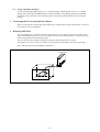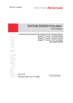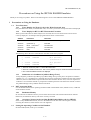
1
HS7046EPH60HE-P (D)
Precautions on Using the SH7046 E6000H Emulator
Thank you for using our product. There are the following notes on use of the SH7046 E6000H Emulator.
1
Precautions on Using the Emulator
1.1
Trace Functions
1.1.1
Trace Display of a Write Cycle for the Write-Protected Area
Only the address bus value, not the data bus value, of a write cycle for the write-protected area is displayed.
1.1.2
Trace Display for BT/S or BT/F Instruction Execution
When a point where BT/S or BT/F is adjacent is executed, the trace execution instruction will not be
correctly displayed. An example of the program and execution is shown below.
Address
Instruction
Execution
*1
xxxxxxx0
BT/S
xxxxxxx2
(instruction 1)
Branches to H'xxxxxxx8 by SR.T = 1
H'xxxxxxx8
Executed
*2
xxxxxxx4
BF/S
xxxxxxx6
(instruction 2)
Not executed
xxxxxxx8
NOP
Executed
H'xxxxxxxx
Not executed
The following shows the trace result after the execution of the above program.
No.
0
BP
-000006
PC
Code
xxxxxxx0
BT/S @H'1008:8
1
(instruction 1)
*3
2
-000005
xxxxxxx4
BF/S @H'1040:8
3
-000004
xxxxxxx8
NOP
Notes: 1. Same as a branch by SR.T = 0 in the BF/S instruction.
2. Same as in the BT/S instruction. This is not a problem except in the BF/S and BT/S instructions.
3. The unexecuted BF/S instruction is displayed.
1.1.3
Satisfaction of a Condition in [Address Range Trace]
If only the [Start] condition of [Address] in [Address Range Trace] on the [Trace Acquisition Condition
Channel n (n = 1 to 11)] dialog box is satisfied, do not specify [Acquisition Condition] for the same channel.
Otherwise, the trace information acquired will be the same as that in the free trace, even if an acquisition
condition is set on another channel or [Acquisition Condition] has been selected for the channel on which
the [Address Range Trace] condition has been satisfied.
1.2
MCU Operating Mode
Use this emulator in the MCU operating mode described in the SH7046 series, SH7047 series, or SH7144
series hardware manual.
1.2.1
Emulation Memory
Do not allocate an emulation memory to areas other than CS that is described in the hardware manual.
Otherwise, the emulation memory will not be correctly accessed.
1.2.2
Accessing CS0 Area in the On-Chip ROM Enabled Mode (only for SH7047)
In the on-chip ROM enabled mode, write 0 to the A0SZ bit in the bus state control register 1 before
accessing the CS0 area, and set the bus size to be eight bits.
1.3
Setting the Operating Condition of the Emulator
Set the H-UDI (JTAG) clock up to 16.0 MHz.
1/5
1.4
Pin Function Controller
This emulator does not support the power port control register (PPCR) of the SH7145. ‘Pin Function
Controller – PPCR’ will not thus be displayed in the [IO] window.
1.5
Coverage Function
For the coverage function, only the command lines (COVERAGE_DISPLAY, COVERAGE_CLEAR, and
COVERAGE_SET) are supported. For details, refer to the on-line help. Coverage data is not initialized
after initiation of the emulator. If you use the coverage function, initialize the coverage data by the
COVERAGE_CLEAR command.
1.6
Detecting the User PVCC Voltage
When the emulator is operated with the user system interface board for the SH7144/SH7145
(HS7144ECH61H or HS7145ECH61H) connected, [OK] is always displayed in [User PVcc] of the
[Extended Monitor] window. Any setting for [User VCC Threshold] of the [Configuration] dialog box is
invalid. To use the user system interface board for the SH7144/SH7145 connected to the emulator, check
the power supply voltage of the user system displayed in [User Vcc] of the [Extended Monitor] window.
1.7
Event Function
1.7.1
Setting a Breakpoint on a SLEEP Instruction
To set a breakpoint on a SLEEP instruction, use a hardware break, not a software break.
The sleep and standby modes will be canceled when the hardware break condition is satisfied or a forced
break is used. The program counter after cancellation of the sleep or standby mode will be located at the
next instruction of SLEEP.
1.8
Step Function
Do not execute a step on a SLEEP instruction.
1.9
Removing Software Breakpoints during the User Program Execution
Do not remove software breakpoints in the source window, [Disassembly] window, or [Label] window
during the user program execution.
1.10 Recovery of Software Breakpoints by the Session File
Information on software breakpoints that was saved in the session file is not available until a load module is
loaded. If necessary, load a load module or set new software breakpoints.
1.11 Display of the Memory Content and Operation of Memory
1.11.1 Operating Memory during Execution of the User Program
The memory copy, memory compare, memory fill, and memory test functions are not available during
execution of the user program. These command lines are not available either.
1.11.2
[Memory] Window
Do not enter a key at a blank in the [Memory] window. Otherwise, the values on the left of the cursor may be
incorrect.
1.11.3
MEMORY_EDIT Command
Do not select the V/N option in the MEMORY_EDIT command. Writing to memory by the
MEMORY_EDIT command always requires no verification.
1.11.4
MEMORY_FILL Command
Do not select the V/N option in the MEMORY_FILL command. Writing to memory by the
MEMORY_FILL command always requires verification.
1.11.5
MEMORY_MOVE Command
Do not select the V/N option in the MEMORY_MOVE command. Writing to memory by the
MEMORY_MOVE command always requires verification.
2/5
1.11.6
Verification of Memory
Use the FILE_VERIFY command to verify memory. Do not use [Verify Memory…] in the [File] menu.
1.12 The Load/Save of File
1.12.1 Loading a File in the SYSROF Format
No program in the SYSROF format can be loaded. Any program for debugging must be created in the
Elf/Dwarf2 format.
1.12.2
FILE_LOAD Command
Do not specify V for the FILE_LOAD command. Use the FILE_VERIFY command to verify memory.
1.12.3
FILE_SAVE Command
The content of memory cannot be saved in the Elf/Dwarf2 format.
1.13 Emulation
1.13.1 Temporary Breakpoints
•
Run... (Run menu)
Do not set temporary breakpoints to an area wherein a software break (User Read-only) cannot be set.
1.13.2
Rate of Stepping
•
To perform stepping continuously with the [Image View] or [Waveform] window open, do not select
“0 seconds” as the delay.
•
Do not perform stepping continuously if you have specified the realtime update of the [Image] or
[Waveform] window.
1.13.3
Go to Cursor
The [Go to Cursor] function uses one software breakpoint. To use the [Go to Cursor] function, the number
of software breakpoints must be 254 or less.
1.13.4
Note on Occurrence of Breaks
When a break occurs during execution of the user program with a dialog box open, the state of HEW may
not transit to the breaking state. In this case, close the dialog box and select [Halt Program] from the [Debug]
menu or press the [Halt Program] button on the toolbar. You can check whether a break has occurred or not
by the RUN lamp (LED) on the emulator station. The RUN lamp (LED) is illuminated while the user
program is running.
1.13.5
Execution Status Display
• Execution Status Display on Status Bar
At memory access wait, the next fetched address is displayed, not the address where the access is halted.
1.13.6
Source-Level Execution
• Step
Even standard C libraries are executed. To return to a higher-level function, enter Step Out. In a for
statement or a while statement, executing a single step does not move execution to the next line. To move
to the next line, execute two steps.
1.14 The Load/Save of the Session File
Load the file after you confirm that the H/W environment is the same as that when the last session file was
loaded.
Note that the operation of HEW may become incorrect when Target Clock is chosen at the time when the
session file was saved and the target clock was not supplied at the time when the session file was loaded.
1.15 Assembling and Disassembling
1.15.1 Line Assembly
•
Input Radix
The default for line assembly input is decimal regardless of the Radix setting. Specify H’ or 0x as the radix
for a hexadecimal input.
3/5
1.16 Note on [Register] Window Operation during the User Program Execution
During user program execution, double-clicking the [Register] window displays a dialog box that allows a
change of the register contents. However, the operation to change the register contents is invalid during the
user program execution.
1.17 [IO] Window
1.17.1 Contents of the [IO] Window
The invalid module display and bit information display in the [IO] window are not supported.
1.18 Source File
1.18.1 Note on the Source File Location after Creating a Load Module
When the source file is moved after the load module has been created, the [Open] dialog box, which
specifies the source file, may be displayed during debugging of the created load module. Select the correct
source file.
1.19 Watch
1.19.1
Local Variables at Optimization
Depending on the generated object code, local variables in a C source file compiled with the optimization
option enabled will not be displayed correctly. Check the generated object code in the [Disassembly]
window.
1.19.2
Variable Name Specification
When a name other than a variable name (such as a symbol name or a function name) is specified, no data is
displayed.
1.19.3
Display of float-type and double-type Variables
Do not enable the automatic update of float-type and double-type variables. The values of float-type and
double-type variables will not be correctly displayed if they are automatically updated during the user
program execution. If you want to check the values, use the monitoring function ([Monitor] window).
1.20 Monitoring Function
1.20.1 Changing Monitor Settings during User Program Execution
If you change the monitor settings in the [Monitor] window during execution of the user program, the initial
values will be undefined.
1.21 Command Line Interface
• Overwrite File
In Command Line Interface, a file that has the same name as the output file is overwritten without asking the
user.
• Log File
To change the target platform due to a change of the session while logging of the command line window,
halt logging.
2
Installation and Uninstallation
2.1
Uninstallation from [Tools Administration]
Note that a message dialog box appears for confirmation if the folder to be removed includes a file other
than those installed. Even though this dialog box is displayed, press the [Ignore] button to continue
uninstallation.
2.2
[Add/Remove Programs Properties] of the Control Panel
Note the followings:
•
Uninstalling from [Add/Remove Programs Properties] of the control panel only removes folders and
files of the product most recently installed if several products that conform to HEW have been
installed. Use the explorer to remove the folders and files of the rest of the products.
•
Once uninstallation is attempted, even the products that were not removed may not operate correctly.
If you want to use these products, re-install them.
4/5
2.3
Usage with Other Products
To install the SuperH™ RISC engine C/C++ compiler package or H8S, H8/300 series C/C++ compiler
package after installing the E6000H emulator software for HEW, select [High-performance Embedded
Workshop] as the component to be installed in [Select Components] during installation of the compiler
package.
3
Connecting the User System Interface Board
Before connecting the evaluation chip board and the user system interface board, check that pin 1 of each of
the connectors is correctly aligned.
4
Reducing EMI Noise
To prevent EMI noise, enclose the evaluation chip board in a case at usage, as shown in the figure below.
The recommended material of the case is iron plated with nickel. For EMI compliance, we have used a case
made of iron plated with nickel during testing.
The case must be large enough to include the evaluation chip board and the user system.
The opening in the case (on the top) should be large enough to let the emulator trace cable go through.
Note: EMI stands for Electrical Magnetic Interference.
E6000H station
E6000H
RENESAS
User system
5/5