1
XT IEC Power Control
XT IEC Power
Control
June 2005
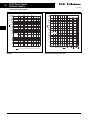
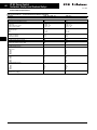
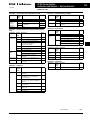
Contents
Description
Page
Relays and Timers
Product Family Overview . . . . . . . . . . . . . . . . . . . . . . . . . . . . . . . . . . . . . . .
Catalog Number Selection . . . . . . . . . . . . . . . . . . . . . . . . . . . . . . . . . . . . . .
Product Selection . . . . . . . . . . . . . . . . . . . . . . . . . . . . . . . . . . . . . . . . . . . . .
Technical Data and Specifications . . . . . . . . . . . . . . . . . . . . . . . . . . . . . . . .
Miniature Controls
Product Family Overview . . . . . . . . . . . . . . . . . . . . . . . . . . . . . . . . . . . . . . .
Catalog Number Selection . . . . . . . . . . . . . . . . . . . . . . . . . . . . . . . . . . . . . .
Product Selection . . . . . . . . . . . . . . . . . . . . . . . . . . . . . . . . . . . . . . . . . . . . .
Technical Data and Specifications . . . . . . . . . . . . . . . . . . . . . . . . . . . . . . . .
Contactors, Starters and Overload Relays
Product Family Overview . . . . . . . . . . . . . . . . . . . . . . . . . . . . . . . . . . . . . . .
Catalog Number Selection . . . . . . . . . . . . . . . . . . . . . . . . . . . . . . . . . . . . . .
Product Selection . . . . . . . . . . . . . . . . . . . . . . . . . . . . . . . . . . . . . . . . . . . . .
Technical Data and Specifications . . . . . . . . . . . . . . . . . . . . . . . . . . . . . . . .
Contactors and Starters — Enclosed Control
Product Family Overview . . . . . . . . . . . . . . . . . . . . . . . . . . . . . . . . . . . . . . .
Catalog Number Selection . . . . . . . . . . . . . . . . . . . . . . . . . . . . . . . . . . . . . .
Product Selection . . . . . . . . . . . . . . . . . . . . . . . . . . . . . . . . . . . . . . . . . . . . .
Modification Codes . . . . . . . . . . . . . . . . . . . . . . . . . . . . . . . . . . . . . . . . . . . .
Manual Motor Protectors
Product Family Overview . . . . . . . . . . . . . . . . . . . . . . . . . . . . . . . . . . . . . . .
Catalog Number Selection . . . . . . . . . . . . . . . . . . . . . . . . . . . . . . . . . . . . . .
Product Selection . . . . . . . . . . . . . . . . . . . . . . . . . . . . . . . . . . . . . . . . . . . . .
Technical Data and Specifications . . . . . . . . . . . . . . . . . . . . . . . . . . . . . . . .
Combination Motor Controllers
Product Family Overview . . . . . . . . . . . . . . . . . . . . . . . . . . . . . . . . . . . . . . .
Catalog Number Selection . . . . . . . . . . . . . . . . . . . . . . . . . . . . . . . . . . . . . .
Product Selection . . . . . . . . . . . . . . . . . . . . . . . . . . . . . . . . . . . . . . . . . . . . .
Technical Data and Specifications . . . . . . . . . . . . . . . . . . . . . . . . . . . . . . . .
Combination Motor Controllers — Enclosed Control
Product Family Overview . . . . . . . . . . . . . . . . . . . . . . . . . . . . . . . . . . . . . . .
Catalog Number Selection . . . . . . . . . . . . . . . . . . . . . . . . . . . . . . . . . . . . . .
Product Selection . . . . . . . . . . . . . . . . . . . . . . . . . . . . . . . . . . . . . . . . . . . . .
Dimensions . . . . . . . . . . . . . . . . . . . . . . . . . . . . . . . . . . . . . . . . . . . . . . . . . .
Reference Data
Approvals for World Markets . . . . . . . . . . . . . . . . . . . . . . . . . . . . . . . . . . . .
IEC Utilization Categories . . . . . . . . . . . . . . . . . . . . . . . . . . . . . . . . . . . . . . .
Motor Ratings Data . . . . . . . . . . . . . . . . . . . . . . . . . . . . . . . . . . . . . . . . . . . .
Enclosure Ratings. . . . . . . . . . . . . . . . . . . . . . . . . . . . . . . . . . . . . . . . . . . . . .
Note: Supplement to Publication No. CAT.02.02.S.K — Tab B , F and Tab J.
XT IEC Power Control
CAT.02.02.S.K.CD
For more information visit:www.EatonElectrical.ca
1
2
3
9
12
13
14
21
28
29
30
54
88
90
91
117
123
126
127
142
159
161
162
167
168
170
171
174
175
178
180
184
XT IEC Power Control
June 2005
For more information visit: www.EatonElectrical.ca
CAT.02.02.S.K.CD
XT IEC Power Control
Relays and Timers
1
June 2005
Product Family Overview
Product Description
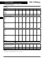
Contents
Description
Catalog Number
Selection . . . . . . . . . . . . . . . .
Product Selection . . . . . . . . . .
Technical Data and
Specifications . . . . . . . . . . . .
Dimensions . . . . . . . . . . . . . . .
Page
2
3
9
11
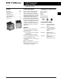
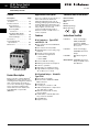
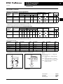
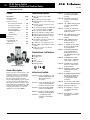
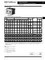
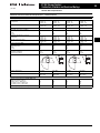
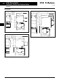
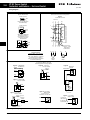
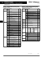
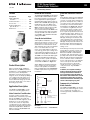
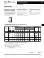
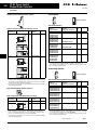
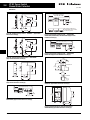
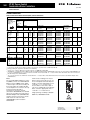
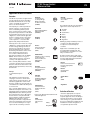
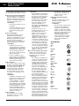
Eaton’s new line of XT Relays and
Timers includes mini and standard
frame control relays and auxiliary
contacts, mini electronic on-delay and
multi-function timers and an electronic
star-delta (wye-delta) timer for use in
star-delta (wye-delta combinations.
Because XT meets UL, CSA, CCC and
CE standards, it is the perfect product
solution for IEC applications all over
the world. The compact, space saving,
and easy to install XT line of IEC
contactors and starters is the efficient
and effective solution for customer
applications.
Features
■
■
■
■
■
■
■
CAT.02.02.S.K.CD
For use with Mini and Standard
frame size contactors and starters
Control Relays
❑ AC Control from 12V to 550V 50
Hz, 600V 60 Hz
❑ DC Control from 12V to 220V
On-Delay and Multi-FunctionTimers
❑ 24 – 240V AC/DC Control
Available with screw or spring cage
terminals
4-Pole Configurations
IP20 finger and back-of-hand proof
Large ambient temperature range –
25° to 50°C [-13° to 122°F]
For more information visit: www.EatonElectrical.ca
Standards and Certifications
■
■
■
■
■
■
IEC EN 60947
CE Approved
UL
CSA
CCC (pending)
ATEX (pending)
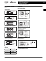
Instructional Leaflets
Pub51219
Inside of Packaging
XTRM Mini Control
Relays
Pub51210
Inside of Packaging
7-15A XTCE Contactors
and XTRE Control
Relays
Pub51244
XTTR Electronic
Star-Delta (Wye-Delta)
Timer
Pub51245
XTMT Mini Electronic
On-Delay and
Multi-Function Timers
2
XT IEC Power Control
Relays and Timers
June 2005
Catalog Number Selection
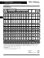
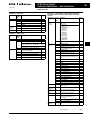
Catalog Number Selection
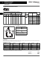
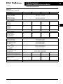
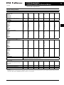
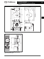
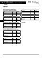
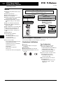
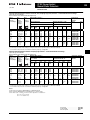
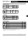
Table 1. XT — Relay Catalog Numbering System
XT RE C 10 B 22 AD
Coil Code
Product Line Prefix
See Table 4 on Page 3.
XT = XT IEC Power Control
Contact
Configuration
Product Family Code
RM = Mini IEC Control Relay
RE = IEC Control Relay
40 = 4NO
31 = 3NO-1NC
22 = 2NO-2NC
Terminations
Frame
Blank = Screw Terminals
C=
Spring Cage Terminals
For XTRM
A = 45 mm — Mini
Conventional
Thermal Current
Rating
For XTRE
B = 45 mm — Standard
10 = 10A
Table 2. XT — Timers Catalog Numbering System
XT MT 6 B 30S 11 B
Coil Code
Product Line Prefix
B = 24 – 240V AC/DC
XT = XT IEC Power Control
Product Family Code
Function
MT = Mini IEC Timing Relay
TR = Star-Delta (Wye-Delta)
Electronic Timing Relay
For XTMT
Time Range Max.
For XTMT
Conventional
Thermal Current
Rating
6 = 6A
Frame
A = 45 mm
30S = 1.5 – 30 s
60H = 0.05 – 1 s
0.15 – 3 s
0.5 – 10 s
3 – 60 s
0.15 – 3 min
0.5 – 3 min
3 – 60 min
0.15 – 3 h
0.5 – 3 h
3 – 60 h
11 = On-Delay
70 = Adjustable
For XTTR
51 = Star-Delta
For XTTR
60S = 3 – 60 s
For more information visit: www.EatonElectrical.ca
CAT.02.02.S.K.CD
XT IEC Power Control
Relays and Timers
3
June 2005
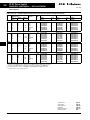
Product Selection
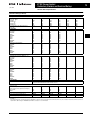
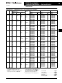
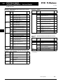
Product Selection
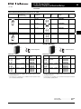
Mini Control Relays
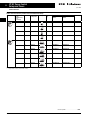
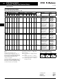
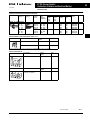
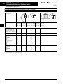
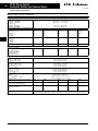
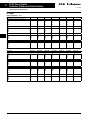
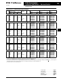
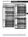
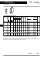
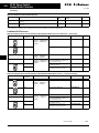
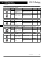
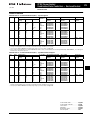
Table 3. Mini Control Relays
Conventional
Thermal
Current
I th (A)
Contact
Configuration
10
4NO
6
3
10
3NO-1NC
6
3
Rated Operational Current
I e AC-15 Amps
220/230/240V
380/400/415V
Circuit
Symbol
A1 13 23 33 43
Screw Terminals
Catalog
Number Spring Cage
Terminals
Catalog
Number XTRM10A40_
XTRMC10A40_
XTRM10A31_
XTRMC10A31_
XTRM10A22_
XTRMC10A22_
Price
AC
Coil
DC
Coil
A2 14 24 34 44
A1 13 21 33 43
A2 14 22 34 44
10
2NO-2NC
6
3
A1 13 21 31 43
A2 14 22 32 44
Underscore (_) indicates magnet coil suffix required. See Table 4.
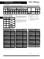
Table 4. Coil Voltage Suffix
Coil Voltage
Suffix Code
Coil Voltage
Suffix Code
Coil Voltage
Suffix Code
110V 50 Hz, 120V 60 Hz
220V 50 Hz, 240V 60 Hz
230V 50 Hz
24V 50/60 Hz
24V DC
415V 50 Hz, 480V 60 Hz
550V 50 Hz, 600V 60 Hz
A
B
F
T
TD C
D
208V 60 Hz
190V 50 Hz, 220V 60 Hz
240V 50 Hz, 277V 60 Hz
380V 50 Hz, 440V 60 Hz
400V 50 Hz
380V 60 Hz
12V 50/60 Hz
E
G
H
L
N
P
R
24V 50 Hz
42V 50 Hz, 48V 60 Hz
48V 50 Hz
120V DC
220V DC
12V DC
48V DC
U
W
Y
AD BD RD WD With DC Operation: Integrated diode-resistor
combination, coil consumption 2.6 kW.
Discount Symbol . . . . . . . . . . . . . . . . . . . . . . . MC8
CAT.02.02.S.K.CD
For more information visit: www.EatonElectrical.ca
XT IEC Power Control
Relays and Timers
4
June 2005
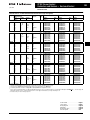
Product Selection
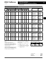
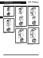
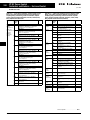
Table 5. Front Mount Auxiliary Contacts for use with XTRM Mini Control Relays
Conventional free air
thermal current,
I th = I e , AC-1 in Amps
Contact
Configuration
10
0NO-2NC
10
1NO-1NC
10
2NO-0NC
10
1NO-1NC
10
0NO-4NC
10
1NO-3NC
10
2NO-2NC
10
3NO-1NC
10
4NO-0NC
10
2NO-2NC
Contact
Sequence
51 61
Package
Qty.
Screw Terminals
Catalog
Number
Spring Cage
Price
Terminals Catalog Number
5
XTMCXFA02
—
5
XTMCXFA11
XTMCXFAC11
5
XTMCXFA20
—
5
XTMCXFAL11 —
5
XTMCXFA04
XTMCXFAC04
5
XTMCXFA13
XTMCXFAC13
5
XTMCXFA22
XTMXCFAC22
5
XTMCXFA31
XTMCXFAC31
5
XTMCXFA40
XTMCXFAC40
5
XTMCXFAL22 XTMCXFCLC22 52 62
53 61
54 62
53 63
54 64
57 65
58 66
51 61 71 81
52 62 72 82
53 61 71 81
54 62 72 82
53 61 71
83
54 62 72
84
53 61 73 83
54 62 74 84
53 63 73 83
54 64 74 84
57 65 71
83
58 66 72
84
Price listed is for a quantity of (1), orders must be placed in multiples of the package quantity listed.
1 early-make contact, 1 late-break contact.
Discount Symbol . . . . . . . . . . . . . . . . . . . . . . . . MC8
For more information visit: www.EatonElectrical.ca
CAT.02.02.S.K.CD
XT IEC Power Control
Relays and Timers
5
June 2005
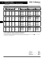
Product Selection
Control Relays
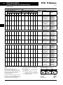
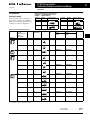
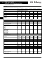
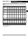
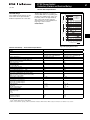
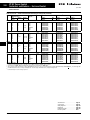
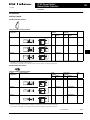
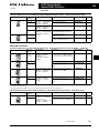
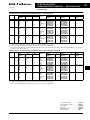
Table 6. Control Relays
Conventional
Thermal
Current I th (A)
Contact
Configuration
10
Rated Operational Current
I e AC-15 Amps
Circuit
Symbol
Screw Terminals Spring Cage Terminals
Catalog
Catalog
Number Number 220/230/240V
380/400/415V
4NO
6
4
10
3NO-1NC
6
4
A1 13 21 33 43
10
2NO-2NC
6
4
A1 13 21 31 43
A1 13 23 33 43
XTRE10B40_
XTREC10B40_
XTRE10B31_
XTREC10B31_
XTRE10B22_
XTREC10B22_
Price
AC
Coil
DC
Coil
A2 14 24 34 44
A2 14 22 34 44
A2 14 22 32 44
Underscore (_) indicates magnet coil suffix required. See Table 7.
Price listed is for a quantity of (1), orders must be placed in multiples of the package quantity listed.
Table 7. Coil Voltage Suffix
Coil Voltage
Suffix Code
Coil Voltage
Suffix Code
Coil Voltage
Suffix Code
110V 50 Hz, 120V 60 Hz
220V 50 Hz, 240V 60 Hz
230V 50 Hz
24V 50/60 Hz
24V DC
415V 50 Hz, 480V 60 Hz
550V 50 Hz, 600V 60 Hz
A
B
F
T
TD C
D
208V 60 Hz
190V 50 Hz, 220V 60 Hz
240V 50 Hz, 277V 60 Hz
380V 50 Hz, 440V 60 Hz
400V 50 Hz
380V 60 Hz
12V 50/60 Hz
E
G
H
L
N
P
R
24V 50 Hz
42V 50 Hz, 48V 60 Hz
48V 50 Hz
120V DC
220V DC
12V DC
48V DC
U
W
Y
AD BD RD WD With DC Operation: Integrated diode-resistor
combination, coil consumption 2.6 kW.
Discount Symbol . . . . . . . . . . . . . . . . . . . . . . . MC8
CAT.02.02.S.K.CD
For more information visit: www.EatonElectrical.ca
XT IEC Power Control
Relays and Timers
6
June 2005
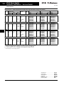
Product Selection
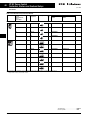
Table 8. Front Mount Auxiliary Contacts for Use with XTRE Control Relays
Conventional
Free Air
Thermal Current,
I th = I e ,
AC-1 in Amps
Poles
Contact
Configuration
Circuit Symbol
10
2
2NO
10
2
1NO-1NC
10
2
2NC
10
2
1NO-1NC
10
4
4NO
10
4
3NO-1NC
10
4
2NO-2NC
10
4
1NO-3NC
10
4
4NC
51 61 71 81
10
4
2NO-2NC
5765 71 83
53 63
Pkg.
Qty.
Screw Terminals
Spring Cage Terminals
Catalog
Number
Catalog
Number
5
XTCEXFAC20
XTCEXFACC20
5
XTCEXFAC11
XTCEXFACC11
5
XTCEXFAC02
XTCEXFACC02
5
XTCEXFALC11 XTCEXFALCC11 5
XTCEXFAC40
XTCEXFACC40
5
XTCEXFAC31
XTCEXFACC31
5
XTCEXFAC22
XTCEXFACC22
5
XTCEXFAC13
XTCEXFACC13
5
XTCEXFAC04
XTCEXFACC04
5
XTCEXFCLC22 XTCEXFCLCC22 Price
54 64
53 61
54 62
51 61
52 62
57 65
58 66
53 6373 83
54 6474 84
53 61 73 83
54 62 74 84
5361 71 83
54 62 72 84
536171 81
54 62 72 82
52 62 72 82
58 66 72 84
Price listed is for a quantity of (1), orders must be placed in multiples of the package quantity listed.
1 early-make contact, 1 late-break contact.
Discount Symbol . . . . . . . . . . . . . . . . . . . . . . . . MC8
For more information visit: www.EatonElectrical.ca
CAT.02.02.S.K.CD
XT IEC Power Control
Relays and Timers
7
June 2005
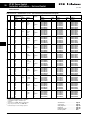
Product Selection
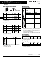
Mini Electronic On-Delay Timers
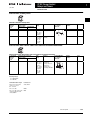
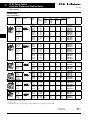
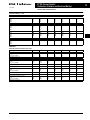
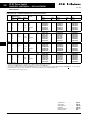
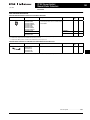
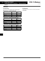
Table 9. Mini Electronic On-Delay Timers
Conventional
Thermal
Current
I e (A)
Rated Operational Current
I e AC-11 Amps
220/230/240V
380/400/440V
6
3
3
6
3
6
Time
Range
Function
Terminal Marking
According to
EN 50042
1.5 – 30 sec
.05 – 1 sec
0.15 – 3 sec
0.5 – 10 sec
3 – 60 sec
0.15 – 3 min
0.5 – 10 min
3 – 60 min
0.15 – 3 h
0.5 – 10 h
3 – 60 h
Fixed,
On-delay
A1
15
A2
16 18
Fixed,
On-delay
Catalog
Number
Price
XTMT6A30S11B
XTMT6A60H11B
Mini Electronic Multi-Function Timers with Connection for Remote Potentiometer
Table 10. Mini Electronic Multi-Function Timers with Connection for Remote Potentiometer
Conventional
Thermal
Current
I e (A)
Rated Operational Current
I e AC-11 Amps
220/230/240V
380/400/440V
Time
Range
Function
6
3
.05 – 1 sec
0.15 – 3 sec
0.5 – 10 sec
3 – 60 sec
0.15 – 3 min
0.5 – 10 min
3 – 60 min
0.15 – 3 h
0.5 – 10 h
3 – 60 h
Adjustable:
On-delayed;
Fleeting contact on
energization;
Flashing; Pulse
generating; ON-OFF
3
Terminal Marking
According to
EN 50042
Z1
Z2
A1
Catalog
Number
Price
XTMT6A60H70B
15
A2 16 18
Notes —
Actuating Voltage
24 – 240 50/60 Hz
24 – 240V DC
Admissible Cable Length
Connection to
Cable unscreened, with
cable cross-section
0.5 – 1.5 mm2
Y1/Y2, Z1/Z2
Two-core cable
M250
Two-core cable in the same
cable duct with the main
cable, 50/60 Hz
M50
Discount Symbol . . . . . . . . . . . . . . . . . . . . . . . MC8
vCAT.02.02.S.K.CD
For more information visit: www.EatonElectrical.ca
XT IEC Power Control
Relays and Timers
8
June 2005
Product Selection
Electronic Star-Delta (Wye-Delta)
Table 11. Electronic Star-Delta (Wye-Delta)
Conventional
Thermal
Current
I e (A)
Rated Operational Current
I e AC-11 Amps
230V
400V
6
3
3
Time
Range
Function
3 – 60 sec
Fixed, Star-Delta
Terminal Marking
According to
EN 50042
A2
18
Price
XTTR6A60S51B
17
A1
Catalog
Number
28
Notes —
Actuating Voltage
24 – 240 50/60 Hz
24 – 240V DC
Admissible Cable Length
Connection to
Cable unscreened, with
cable cross-section
0.5 – 1.5 mm2
B1, Z1/Z2
Two-core cable
M250
Two-core cable in the same
cable duct with the main
cable, 50/60 Hz
M50
Discount Symbol . . . . . . . . . . . . . . . . . . . . . . . . MC8
For more information visit: www.EatonElectrical.ca
CAT.02.02.S.K.CD
XT IEC Power Control
Relays and Timers
9
June 2005
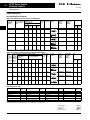
Technical Data and Specifications
Technical Data and Specifications
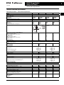
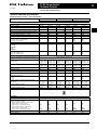
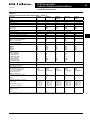
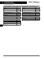
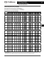
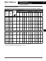
Table 12. Relays and Timers — Technical Data and Specifications
Description
XTRE
XTCEXFAC_
XTRM
XTMCXFA_
General
Standards
Lifespan, Mechanical
AC Operated
DC Operated
Maximum operating frequency (ops/hr)
IEC/EN 60947, VDE 0660, UL, CSA
20,000,000
20,000,000
9000
Climatic Proofing
Ambient Temperature
Open (°C)
Enclosed (°C)
Ambient Temperature for Storage (°C)
Mounting Position
10,000,000
10,000,000
9000
10,000,000
20,000,000
9000
10,000,000
20,000,000
9000
Damp heat, constant, to IEC 60068-2-78; Damp heat, cyclical, to IEC 60068-2-30
-25/60
-25/40
-40/80
-25/60
-25/40
-40/80
30°
90°
90°
-25/50
-25/50
-25/40
-25/40
—
—
As required, except vertically A1/A2 at
the bottom
90°
180°
Mechanical shock resistance (IEC/EN 60068-2-27)
Half-sinusoidal shock 10 ms
Base unit with auxiliary contact module
Make contact
Break contact
Half-sinusoidal shock 20 ms
Base unit with auxiliary contact module
Make contact
Break contact
Degree of Protection
Protection against direct contact from the front when actuated by a perpendicular test finger (IEC 536)
Weight
AC operated (kg)
DC operated (kg)
Terminal capacity
Screw terminals
Solid (mm2)
7g
5g
—
—
—
—
IP20
—
—
IP20
0.23
0.28
0.23
0.28
Flexible with ferrule (mm2)
Solid or stranded (AWG)
Terminal screw
Pozidriv screwdriver
Standard screwdriver (mm)
M3.5
Size 2
Max. tightening torque (Nm)
Spring cage terminals
Solid (mm2)
1.2
10g
8g
—
—
IP20
Finger- and back-of-hand proof
1 x (0.75 – 4)
2 x (0.75 – 2.5)
1 x (0.75 – 2.5)
2 x (0.75 – 2.5)
18 – 14
M3.5
Size 2
0.8 x 5.5
1x6
1.2
0.17
0.20
M3.5
Size 2
1.2
Solid or stranded (AWG)
Standard screwdriver (mm)
—
—
IP20
—
—
1 x (0.75 – 2.5)
2 x (0.75 – 2.5)
1 x (0.75 – 1.5)
2 x (0.75 – 1.5)
18 – 14
M3.5
Size 2
0.8 x 5.5
1x6
1.2
1 x (0.75 – 2.5)
2 x (0.75 – 2.5)
1 x (0.75 – 2.5)
2 x (0.75 – 2.5)
18 – 14
1 x (0.75 – 2.5)
2 x (0.75 – 2.5)
1 x (0.75 – 2.5)
2 x (0.75 – 2.5)
18 – 14
Flexible with or without ferrule DIN 46228 (mm 2)
10g
8g
0.6 x 3.5
Contacts
Interlocked opposing contacts to ZH 1/457,
including auxiliary contact module
Rated impulse withstand voltage (U imp) V AC
Overvoltage category/pollution degree
Rated insulation voltage (U i) V AC
Rated operational voltage (U e) V AC
Safe isolation to VDE 0106 Part 101 and Part 101/A1
Between coil and auxiliary contacts (V AC)
Between the auxiliary contacts (V AC)
Rated operational current
AC-15 220/240V Ie
380/415V Ie
500V Ie
CAT.02.02.S.K.CD
—
—
Yes
Yes
6000
III/3
690
690
6000
III/3
690
500
6000
III/3
690
600
6000
III/3
690
600
400
400
400
400
300
300
300
300
6
4
1.5
6
3
—
6
3
1.5
4
2
1.5
For more information visit: www.EatonElectrical.ca
XT IEC Power Control
Relays and Timers
10
June 2005
Technical Data and Specifications
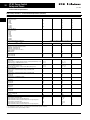
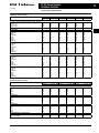
Table 12. Relays and Timers — Technical Data and Specifications (Continued)
Description
XTRE
XTCEXFAC_
XTRM
XTMCXFA_
2.5
1
3
0.5
3
0.25
1
—
—
—
—
—
—
—
2.5
—
2.5
—
1.5
—
0.5
2.5
—
2.5
—
1.5
—
0.5
—
4
—
4
—
2
—
1
—
—
—
—
—
—
—
—
—
—
—
—
—
—
—
—
—
—
—
—
—
—
—
—
Contacts (Continued)
DC-13 DC-13 L/R ≤ 15 mS
Contacts in series:
1:24V
1:60V
2:60V
1:110V
3:110V
1:220V
3:220V
DC-13 L/R ≤ 50 mS
Contacts in series:
2:24V
3:24V
2:60V
3:60V
1:110V
3:110V
1:220V
3:220V
<10-8, < one failure in 10 million operations center
Contact reliability Fault probability (λ)
(at Ue = 24V DC, Umin = 17, Imin = 5.4 mA)
Conventional thermal current (I th)
Short-circuit rating without welding
Maximum overcurrent protective device
220/240V – XTPR Frame B
380/415V – XTPR Frame B
Short-circuit protection, max. fuse 500V (a gG/gL)
500V (A fast)
Current heat losses at load of I th
AC operated (W)
DC operated (W)
10
10
10
10
4
4
—
—
4
4
4
4
10
—
10
—
6
10
6
10
0.3
0.3
0.3
0.3
0.2
0.3
0.2
0.3
0.8 – 1.1
0.8 – 1.1
—
—
0.8 – 1.1
0.85 – 1.1
—
—
0.8 – 1.1
0.7 – 1.3
—
—
0.85 – 1.3
0.7 – 1.3
—
—
24
19
—
—
25
22
—
—
4
1.2
—
—
4.6
1.3
—
—
28
22
—
—
30
26
—
—
4.6
1.4
—
—
5.4
1.6
—
—
26
21
—
—
29
24
—
—
3.9
1.2
—
—
3.9
1.2
—
—
3
100
—
—
2.6
100
—
—
≤ 20
≤15
—
≤35
≤15
—
—
—
—
—
—
—
14 – 21
8 – 18
45
26 – 35
15 – 25
70
—
—
45
—
—
70
Magnet Systems
Pick-up and drop-out values
AC operated
Single-voltage coil 50 Hz and dual-voltage coil 50 Hz, 60 Hz (Pick-up x U c)
Dual-frequency coil 50/60 Hz (Pick-up x U c)
DC operated Pick -up voltage (Pick-up x U c)
At 24V: without auxiliary contact module (40°C) (Pick-up x U c)
Power consumption
Single-voltage coil 50 Hz and dual-voltage coil 50 Hz, 60 Hz
Pick-up VA
Pick-up W
Single-voltage coil 50 Hz and dual-voltage coil 50 Hz, 60 Hz
Sealing VA
Sealing W
Dual-frequency coil 50/60 Hz at 50 Hz
Pick-up VA
Pick-up W
Dual-frequency coil 50/60 Hz at 50 Hz
Sealing VA
Sealing W
Dual-frequency coil 50/60 Hz at 60 Hz
Pick-up VA
Pick-up W
Dual-frequency coil 50/60 Hz at 60 Hz
Sealing VA
Sealing W
DC operated
Pull-in = sealing (W)
Duty factor
Switching times at 100% U c (approximate values)
AC operated closing delay (mS)
AC operated make contact opening delay (mS)
AC operated with auxiliary contact module, max. closing delay (mS)
DC operated closing delay (mS)
DC operated make contact opening delay (mS)
DC operated with auxiliary contact module, max. closing delay (mS)
Making and breaking conditions to DC13, time constant as stated.
See transparent overlay “Fuses” for time/current characteristics (please enquire).
Smoothed DC or three-phase bridge rectifier
For more information visit: www.EatonElectrical.ca
CAT.02.02.S.K.CD
XT IEC Power Control
Relays and Timers
11
June 2005
Technical Data and Specifications
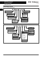
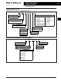
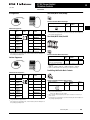
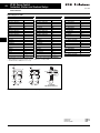
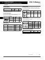
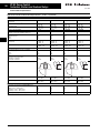
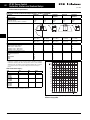
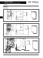
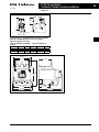
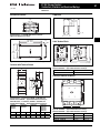
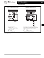
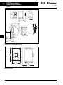
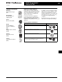
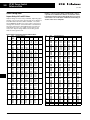
Flow Diagrams — Electronic
Timers
XTMT Mini Timers
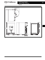
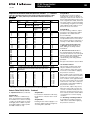
Dimensions
Mini Contactor Relays
5.5 [.22]
A1-A2
15-18
t
LED
58
[2.28
Figure 1. On-Delayed
[1.77]
OFF
A1-A2
15-18
ON OFF
LED
–
[2.05] – [2.13]
Figure 7. Mini Control Relay XTRM —
Approximate Dimensions in mm [in.]
Figure 2. ON-OFF Function
43
[1.69]
A1-A2
15-18
t
LED
58
[2.28]
Figure 3. Fleeting Contact on Energization
A1-A2
15-18
t
t
t
t
45
[1.77]
45
[1.77]
65.3
[2.57]
Figure 8. XTRM Mini Control Relay with IP40
XTMCX Shroud — Approximate
Dimensions in mm [in.]
LED
Figure 4. Flashing, Pulse Initiating
A1-A2
15-18
0.5 s
t
45
[1.77]
LED
Figure 5. Pulse Generating
Star-Delta (Wye-Delta) Timer
–
–
13]
Figure 9. XTRM Mini Control Relay with RC or
Varistor Suppressor — Approximate
Dimensions in mm [in.]
M4
A1-A2
17-18
17-28
t
tu
Power LED
LED
LED
Figure 6. Star-Delta
50
[1.97]
[1.77]
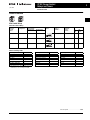
Rating Data
Table 13. Rating Data for Approved Types
Pilot Duty
58
83 – 86
[3.27] – [3.39]
Figure 10. XTRM Mini Control Relay with XTMCXPA Auxiliary Control
— Approximate Dimensions in mm [in.]
General Use
Control Relays — XTMR
A600, P300
10A – 600V AC
0.5A – 250V DC
Timers — XTMT, XTTR
B300
CAT.02.02.S.K.CD
35
[1.38]
6A – 250V AC
For more information visit: www.EatonElectrical.ca
12
XT IEC Power Control
Miniature Controls
June 2005
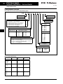
Product Family Overview
Contents
Description
Catalog Number
Selection . . . . . . . . . . . . . . . .
Product Selection . . . . . . . . . .
Non-reversing
Mini Contactors . . . . . . . . .
Reversing Mini
Contactors . . . . . . . . . . . . .
Star-Delta (Wye-Delta)
Miniature Contactors . . . .
Overload Relays. . . . . . . . . .
Accessories . . . . . . . . . . . . . . .
Technical Data and
Specifications . . . . . . . . . . . .
Dimensions . . . . . . . . . . . . . . .
Page
13
14
14
15
16
17
18
21
27
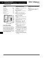
Application Description
Standards and Certifications
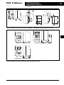
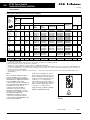
Due to its compact size, the XT line of
mini controls is best suited to be
applied in light duty loads such as
hoisting, packaging, material handling,
heating, lighting and automation systems. XT mini contactors are a particularly compact, economic and
environmentally friendly solution
wherever control of small motors or
loads is required.
■
Features
Instructional Leaflets
Mini Contactors — Types XTMC
and XTMF, 6 – 9A
Pub51219
■
■
■
■
■
■
■
■
■
XTMC Mini Contactor
Product Description
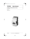
Eaton’s new line of Cutler-Hammer®
XT Miniature Controls includes nonreversing and reversing mini contactors,
mini overload relays and snap-on
accessories. A wide range of applications is possible including small
electrical motors from fractional to
5 hp (460V AC) or up to 4 kW
(400V AC).
■
AC Control from 12V to 550V 50 Hz,
600V 60 Hz
DC Control from 12V to 220V
Available with screw or spring cage
terminals
Reversing or Non-reversing
3 and 4-Pole Configurations
❑ 3-Pole XTMC
❑ 4-Pole XTMF
Panel or DIN rail mounting
IP20 finger and back-of-hand proof
Low noise operation
High degree of climatic proofing
Large ambient temperature range
-25° to 50°C [-13° to 122°F]
■
■
■
■
■
IEC EN 60947
CE Approved
UL
CSA
ATEX (pending)
CCC (pending)
Inside of Packaging
XTMC, XTMF Mini
Contactors, XTRM
Mini Control Relay and
Accessories
Pub51243
Inside of Packaging
XTOM Mini Overload
Relays
Pub51206
Mini Reversing Link
Kits
MN03402002E XTOM Mini Overload
Relays Installation and
User Manual
Mini Overload Relays — Bimetallic
Type XTOM
■
■
■
■
■
■
■
■
■
Phase failure sensitivity
Direct mount to XTMC and XTMF
Mini Contactors
Trip Class 10
11 settings to cover 0.1 to 12A
Ambient temperature compensated
-5° to 50°C [23° to 122°F]
Manual and automatic reset by
selector switch
1 Make (NO) or 1 Break (NC) auxiliary contact as standard
Test/Off Button
Trip-free release
For more information visit: www.EatonElectrical.ca
CAT.02.02.S.K.CD
XT IEC Power Control
Miniature Controls
13
June 2005
Catalog Number Selection
Catalog Number Selection
Table 14. XT IEC Miniature Contactors — Catalog Numbering System
XT MC C 6 A 10 A
Coil Codes
Designation
A=
B=
F=
T=
TD =
C=
D=
E=
G=
H=
L=
XT = XT IEC Power Control
Type
MC = 3-Pole FVNR Mini IEC Contactor
MF = 4-Pole FVNR Mini IEC Contactor
MR = 3-Pole FVR Mini IEC Contactor
Terminations
110V 50 Hz, 120V 60 Hz
220V 50 Hz, 240V 60 Hz
230V 50 Hz
24V 50/60 Hz
24V DC
415V 50 Hz, 480V 60 Hz
550V 50 Hz, 600V 60 Hz
208V 60 Hz
190V 50 Hz, 220V 60 Hz
240V 50 Hz, 277V 60 Hz
380V 50 Hz, 440V 60 Hz
Blank = Screw Terminals
C = Spring Cage Terminals
Integral Auxiliary Contact
01 = 1NC
10 = 1NO
Current Rating, AC-3
XTMC
6 = 6.6A
9 = 9.0A
Frame Size
A = 45 mm Mini
XTMF
9 = 9.0A
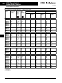
Table 15. XT IEC Miniature Overload Relays — Catalog Numbering System
XT OM P16 A C1
Trip Class
Designation
C1 = Class 10A
XT = XT IEC Power Control
Type
OM = Mini Overload Relay
Frame Size
A = 45 mm Mini
Overload Release
P16 =
P24 =
P40 =
P60 =
001 =
1P6 =
2P4 =
004 =
006 =
009 =
012 =
CAT.02.02.S.K.CD
0.1 – 0.16A
0.16 – 0.24A
0.24 – 0.4A
0.4 – 0.6A
0.6 – 1A
1 – 1.6A
1.6 – 2.4A
2.4 – 4A
4 – 6A
6 – 9A
9 – 12A
For more information visit: www.EatonElectrical.ca
N=
P=
R=
U=
W=
Y=
AD =
BD =
RD =
WD =
400V 50 Hz
380V 60 Hz
12V 50/60 Hz
24V 50 Hz
42V 50 Hz, 48V 60 Hz
48V 50 Hz
120V DC
220V DC
12V DC
48V DC
XT IEC Power Control
Miniature Controls
14
June 2005
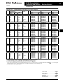
Product Selection
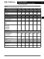
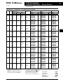
Product Selection
Non-reversing Mini Contactors
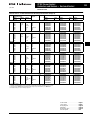
Table 16. Full Voltage Non-reversing Contactors with kW RATINGS
Operational
Current AC-3
Amp Rating
380/400V
Conventional
Free Air Thermal
Current AC-1 at
50°C
Maximum
kW Ratings AC-3
3-Phase Motors
50 – 60Hz
220 – 380 – 550V
240V 400V
No. of
Power
Poles
660/
690V
Auxiliary Circuit
Contacts Symbol
Spring Cage
Terminals
Catalog
Number Screw
Terminals
Catalog
Number Price
AC
Coil
6.6
20
1.5
3
3
3
3
1NO
6.6
20
1.5
3
3
3
3
1NC
A1 1 3 5 21
8.8
20
2.2
4
4
4
3
1NO
A1 1 3 5 13
8.8
20
2.2
4
4
4
3
1NC
A1 1 3 5 21
8.8
20
2.2
4
4
4
4
—
A1 1 3 5 13
XTMC6A10_
XTMCC6A10_
XTMC6A01_
XTMCC6A01_
XTMC9A10_
XTMCC9A10_
XTMC9A01_
XTMCC9A01_
XTMF9A00_
—
DC
Coil
A2 2 4 6 14
A2 2 4 6 22
A2 2 4 6 14
A2 2 4 6 22
A1 1 3 5 7
A2 2 4 6 8
Underscore (_) indicates Magnetic Coil Suffix required. See Table 18.
Table 17. Full Voltage Non-reversing Contactors with HORSEPOWER RATINGS
Spring Cage
Terminals
Catalog
Number Operational
Current
AC-3 Amp
Rating
380/400V
Conventional
Free Air
Thermal
Current
AC-1 at
50°C
Maximum Three-phase Motor Rating
1-Phase
3-Phase
Horsepower
Horsepower Ratings
Ratings
115V
200V
230V
200V
230V
460V
575V
6.6
20
1/4
3/4
1
1-1/2
2
3
3
3
1NO
A1 1 3 5 13
XTMC6A10_
XTMCC6A10_
6.6
20
1/4
3/4
1
1-1/2
2
3
3
3
1NC
A1 1 3 5 21 XTMC6A01_
XTMCC6A01_
8.8
20
1/2
1
1-1/2
2
3
5
5
3
1NO
A1 1 3 5 13
XTMC9A10_
XTMCC9A10_
8.8
20
1/2
1
1-1/2
2
3
5
5
3
1NC
A1 1 3 5 21 XTMC9A01_
XTMCC9A01_
8.8
20
1/2
1
1-1/2
2
3
5
5
4
—
No. of Aux.
Power ConPoles tacts
Circuit
Symbol
Screw
Terminals
Catalog
Number Price
AC
Coil
DC
Coil
A2 2 4 6 14
A2 2 4 6 22
A2 2 4 6 14
A2 2 4 6 22
A1 1 3 5 7
XTMF9A00_
—
A2 2 4 6 8
Underscore (_) indicates Magnetic Coil Suffix required. See Table 18.
Table 18. Magnet Coil Suffix
Coil Voltage
Suffix
Code
Coil Voltage
Suffix
Code Coil Voltage
Suffix
Code Coil Voltage
Suffix
Code 110V 50 Hz, 120V 60 Hz
220V 50 Hz, 240V 60 Hz
230V 50 Hz
24V 50/60 Hz
24V DC
—
A
B
F
T
TD —
415V 50 Hz, 480V 60 Hz
550V 50 Hz, 600V 60 Hz
208V 60 Hz
190V 50 Hz, 220V 60 Hz
240V 50 Hz, 277V 60 Hz
380V 50 Hz, 440V 60 Hz
C
D
E
G
H
L
400V 50 Hz
380V 60 Hz
12V 50/60 Hz
24V 50 Hz
42V 50 Hz, 48V 60 Hz
48V 50 Hz
N
P
R
U
W
Y
120V DC
220V DC
12V DC
48V DC
—
—
AD
BD
RD
WD
—
—
For indicated coils, price adder of 10% must be applied to the contactor list price in Tables 16 and 17.
With DC Operation: Integrated diode resistor combination, coil rating 2.6W.
Overload Relays. . . . . . . . . . . . . . . . . . . . . . . Page 17
Accessories . . . . . . . . . . . . . . . . . . . . . . . . . . Page 18
Dimensions . . . . . . . . . . . . . . . . . . . . . . . . . . Page 27
Discount Symbol . . . . . . . . . . . . . . . . . . . . . . MC8
For more information visit: www.EatonElectrical.ca
CAT.02.02.S.K.CD
XT IEC Power Control
Miniature Controls
15
June 2005
Product Selection
Reversing Mini Contactors
Table 19. Full Voltage Reversing Contactors with kW RATINGS
Operational
Current AC-3
Amp Rating
380/400V
Conventional
Maximum kW Ratings AC-3
Free Air Thermal 3-Phase Motors 50 – 60 Hz
Current AC-1 at
220/230/240V 380/400/440V
50°C
500V
660/690V
6.6
20
1.5
3
3
3
33
34
34
8.8
20
2.2
4
4
4
33
33
34
34
Spare Auxiliary Contacts
K1M
K2M
Forward
Reversing
Contactor
Contactor
Catalog
Number Price
AC
DC
XTMR6A21_
33
XTMR9A21_
Underscore (_) indicates Magnetic Coil Suffix required. See Table 21.
The factory installed reversing mini contactor includes (2) XTMC…10_ Contactors, (2) XTMCXFD11 1NO1NC Front Mount Auxiliary Contacts (1)
XTMCXRL Reversing Link Kit and (1) XTMCXML Mechanical Interlock.
Table 20. Full Voltage Reversing Contactors with HORSEPOWER RATINGS
Operational
Current AC-3
Amp Rating
380/400V
Conventional
Maximum 3-Phase Current Motor Rating
Free Air Thermal 1-Phase hp Ratings
3-Phase hp Ratings
Current AC-1 at
115V
200V
230V
200V
230V 460V
50°C
575V
6.6
20
1/4
3/4
1
1-1/2
2
3
3
33
33
34
34
8.8
20
1/2
1
1-1/2
2
3
5
5
33
33
34
34
Spare Auxiliary Contacts
K1M
K2M
Catalog
Number Price
AC
DC
XTMR6A21_
XTMR9A21_
Underscore (_) indicates Magnetic Coil Suffix required. See Table 21.
The factory installed reversing mini contactor includes (2) XTMC…10_ Contactors, (2) XTMCXFD11 1NO1NC Front Mount Auxiliary Contacts (1)
XTMCXRL Reversing Link Kit and (1) XTMCXML Mechanical Interlock.
Table 21. Magnet Coil Suffix
Coil Voltage
Suffix
Code
Coil Voltage
Suffix
Code Coil Voltage
Suffix
Code Coil Voltage
Suffix
Code 110V 50 Hz, 120V 60 Hz
220V 50 Hz, 240V 60 Hz
230V 50 Hz
24V 50/60 Hz
24V DC
—
A
B
F
T
TD —
415V 50 Hz, 480V 60 Hz
550V 50 Hz, 600V 60 Hz
208V 60 Hz
190V 50 Hz, 220V 60 Hz
240V 50 Hz, 277V 60 Hz
380V 50 Hz, 440V 60 Hz
C
D
E
G
H
L
400V 50 Hz
380V 60 Hz
12V 50/60 Hz
24V 50 Hz
42V 50 Hz, 48V 60 Hz
48V 50 Hz
N
P
R
U
W
Y
120V DC
220V DC
12V DC
48V DC
—
—
AD
BD
RD
WD
—
—
For indicated coils, price adder of 10% must be applied to the contactor list price in Tables 19 and 20.
With DC Operation: Integrated diode resistor combination, coil rating 2.6W.
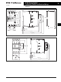
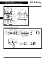
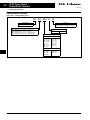
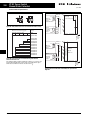
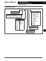
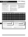
Notes:
IEC Utilization Categories, see Page 178,
Reference Data.
21
0
22
II
21
22
22
1 3 5
K1M
21
AC-1: Non-inductive or slightly inductive
loads.
2 4 6
AC-2: Squirrel-cage motors — starting,
switching of motors during running.
K2M
2 4 6
13
14
13
14 14
14
K1M
K2M
13
13
22
K1M 22
K2M 21
21
A1 K2M A1
K1M
A2
A2
13 5
I
AC-3: Squirrel-cage motors — starting,
plugging, inching.
UV W
M1
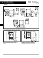
Figure 11. XTMR Reversing Contactor Control
Wiring Diagram
M
3
Figure 12. XTMR Reversing Contactor Power
Wiring Diagram
Overload Relays . . . . . . . . . . . . . . . . . . . . . .
Accessories . . . . . . . . . . . . . . . . . . . . . . . . . .
Dimensions . . . . . . . . . . . . . . . . . . . . . . . . . .
Discount Symbol . . . . . . . . . . . . . . . . . . . . .
CAT.02.02.S.K.CD
For more information visit: www.EatonElectrical.ca
Page 17
Page 18
Page 27
MC8
XT IEC Power Control
Miniature Controls
16
June 2005
Product Selection
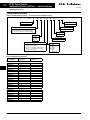
Star-Delta (Wye-Delta) Miniature Contactors
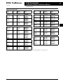
Table 22. Star-Delta (Wye-Delta) Miniature Contactor Configuration Maximum kW Ratings AC-3
Maximum 3-Phase Current Motor Rating
Max.
Changeover
1-Phase hp
3-Phase hp Ratings
Time (sec.)
Ratings
115V 200V 230V 200V 230V 460V 575V
3-Phase Motors 50 – 60 Hz
220/230/ 380/400/ 500V
240V
440V
4
5.5
5.5
1/2
1
1-1/2 2
3
5
Spare
Auxiliary
Contacts
7-1/2 30
21 31 53
Price
K1M
22 32 54
Component Catalog Number
Description
Catalog Number
AC
K1M Main
Contactor
K1M Auxiliary
Contact
K5M Delta
Contactor
K3M Star
Contactor
K3M Auxiliary
Contact
K1T Timing
Relay
DC
XTMC9A10_
XTMCXFC22
XTMC9A01_
XTMC9A10_
XTMCXFC02
XTTR6A60S51B
Operating Frequency: 30 Starts/hour
Underscore (_) indicates magnet coil suffix required. See Table 24.
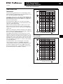
Table 23. Mini Overload Relay Settings (A)
B
K1M
1 3 5
K5M
24 6
13 5
K3M
24 6
A
Setting
Starting
A: IN x 0.58
≤ = 15 sec
Motor Protection in the Y and Delta
Configurations.
1 35
B: IN x 1
246
15 – 40 sec
Only partial motor protection in star position
C
C: IN x 0.58
> 40 sec
Motor not protected in star position.
Timing Relay set to approximately 10 sec.
U1
V1 M1
W1 3
M1
V2
W2
U2
Figure 13. Star-Delta (Wye-Delta) Power
Wiring Diagram
Note: Depending on the coordination type required (i.e. Type 1 or Type 2) it must be established whether the fuse protection and the input wiring for the main and delta contactors are to be common or separate.
Table 24. Magnet Coil Suffix
Coil Voltage
Suffix
Code
Coil Voltage
Suffix
Code Coil Voltage
Suffix
Code Coil Voltage
Suffix
Code 110V 50 Hz, 120V 60 Hz
220V 50 Hz, 240V 60 Hz
230V 50 Hz
24V 50/60 Hz
24V DC
—
A
B
F
T
TD —
415V 50 Hz, 480V 60 Hz
550V 50 Hz, 600V 60 Hz
208V 60 Hz
190V 50 Hz, 220V 60 Hz
240V 50 Hz, 277V 60 Hz
380V 50 Hz, 440V 60 Hz
C
D
E
G
H
L
400V 50 Hz
380V 60 Hz
12V 50/60 Hz
24V 50 Hz
42V 50 Hz, 48V 60 Hz
48V 50 Hz
N
P
R
U
W
Y
120V DC
220V DC
12V DC
48V DC
—
—
AD
BD
RD
WD
—
—
For indicated coils, price adder of 10% must be applied to the contactor list price in Table 22.
With DC Operation: Integrated diode resistor combination, coil rating 2.6W.
Overload Relays. . . . . . . . . . . . . . . . . . . . . . . Page 17
Accessories . . . . . . . . . . . . . . . . . . . . . . . . . . Page 18
Dimensions . . . . . . . . . . . . . . . . . . . . . . . . . . Page 27
Discount Symbol . . . . . . . . . . . . . . . . . . . . . . MC8
For more information visit: www.EatonElectrical.ca
CAT.02.02.S.K.CD
XT IEC Power Control
Miniature Controls
17
June 2005
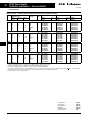
Product Selection
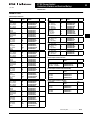
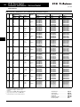
Overload Relays
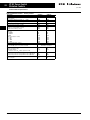
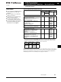
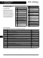
Table 25. Mini Overload Relays Overload
Release It
Trip
Class
0.1 – 0.16A
0.16 – 0.24A
0.24 – 0.4A
0.4 – 0.6A
10A
0.6 – 1A
1 – 1.6A
1.6 – 2.4A
10A
2.4 – 4A
4 – 6A
6 – 9A
9 – 12A
10A
Contact
Sequence
97 95
2 4 6 98 96
Contact
Configuration
Short Circuit Protection (A)
Type 1
Type 2
Coordination, Coordination,
gG/gL
gG/gL
Circuit
Breaker
CEC/NEC
Fuse
Catalog
Number
1NO-1NC
20
20
20
20
0.5
1
2
2
15
15
15
15
—
—
—
—
XTOMP16AC1
XTOMP24AC1
XTOMP40AC1
XTOMP60AC1
1NO-1NC
20
20
20
4
6
6
15
15
15
3
6
6
XTOM001AC1
XTOM1P6AC1
XTOM2P4AC1
1NO-1NC
20
20
20
—
10
10
10
—
15
15
15
—
15
20
35
45
XTOM004AC1
XTOM006AC1
XTOM009AC1
XTOM012AC1
Price
Short-circuit protection:
Observe the maximum permissible fuse of the contactor with direct device mounting. See MN03402002E for more information.
When fitted directly to the contactor, a clearance of at least 5 mm is required between the overload relays.
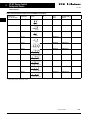
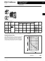
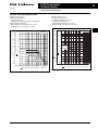
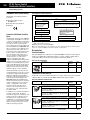
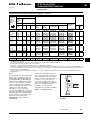
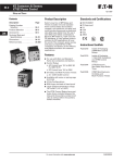
Tripping Characteristics Chart
2h
100
60
40
Minutes
These tripping characteristics are mean values of the spread
at 20°C ambient temperature in a cold state. Tripping time
depends on response current. With devices at operating
temperature, the tripping time of the overload relay reduces
to approx. 25% of the read off value. Specific characteristics
for each individual setting range can be found on Page 25.
XTOM
20
10
6
4
2
1
40
3-Phase
Seconds
20
10
6
4
2-Phase
2
1
0.6
1
1.5 2
3
4
6
8 10 15
20
x Setting Current
Figure 14. Tripping Characteristics
Dimensions . . . . . . . . . . . . . . . . . . . . . . . . . . Page 27
Discount Symbol . . . . . . . . . . . . . . . . . . . . . . MC8
CAT.02.02.S.K.CD
For more information visit: www.EatonElectrical.ca
XT IEC Power Control
Miniature Controls
18
June 2005
Accessories
Accessories
Auxiliary Contacts
Front mounted snap-on auxiliary contacts for mini contactors are available with screw or spring cage terminals in a variety of
contact configurations. Auxiliary contact modules are standard with interlocked opposing contacts, except in the case of earlymake or late-break contacts.
Table 26. Front Mount Auxiliary Contacts for Use with Mini Contactors
Conventional free air
thermal current,
Ith = Ie, AC-1 in Amps
Contact
Configuration
10
0NO-2NC
10
1NO-1NC
10
2NO-2NC
10
0NO-2NC
10
1NO-1NC
10
2NO-0NC
10
1NO-1NC
10
0NO-4NC
10
1NO-3NC
10
2NO-2NC
10
3NO-1NC
10
4NO-0NC
10
2NO-2NC
Contact
Sequence
21 31
Package
Qty.
Screw Terminals
Catalog
Number
Spring Cage
Price
Terminals Catalog Number
5
XTMCXFC02
—
5
XTMCXFD11
XTMCXFDC11
5
XTMCXFC22
XTMCXFCC22
5
XTMCXFA02
—
5
XTMCXFA11
XTMCXFAC11
5
XTMCXFA20
—
5
XTMCXFAL11 —
5
XTMCXFA04
XTMCXFAC04
5
XTMCXFA13
XTMCXFAC13
5
XTMCXFA22
XTMXCFAC22
5
XTMCXFA31
XTMCXFAC31
5
XTMCXFA40
XTMCXFAC40
5
XTMCXFAL22 XTMCXFCLC22 22 32
21
33
22
34
21 31 43 53
22 32 44 54
51 61
52 62
53 61
54 62
53 63
54 64
57 65
58 66
51 61 71 81
52 62 72 82
53 61 71 81
54 62 72 82
53 61 71
83
54 62 72
84
53 61 73 83
54 62 74 84
53 63 73 83
54 64 74 84
57 65 71
83
58 66 72
84
1 early-make contact, 1 late-break contact.
Price listed is for a quantity of (1), orders must be placed in multiples of
the package quantity listed.
For more information visit: www.EatonElectrical.ca
Discount Symbol . . . . . . . . . . . . . . . . . . . . . . . MC8
CAT.02.02.S.K.CD
XT IEC Power Control
Miniature Controls
19
June 2005
Accessories
RC Suppressor
Star-Delta (WYE-Delta) Bridge
Table 29. Star-Delta (WYE-Delta) Bridge
Contact Sequence
Package Catalog
Qty.
Number
20
XTMCXSDB
Price
Table 27. RC Suppressor Voltage
24 – 48
48 – 130
110 – 250
24 – 48
48 – 130
110 – 250
For Use
With —
Circuit
Symbol
XTMC6A…, A1
XTMC9A…
XTMC6A…,
XTMC9A…
A2
XTMC6A…,
XTMC9A…
XTMCC6A…,
XTMCC9A…
XTMCC6A…,
XTMCC9A…
XTMCC6A…,
XTMCC9A…
Package Catalog
Qty.
Number
10
XTMCXRSW
10
XTMCXRSA
10
XTMCXRSB
10
XTMCXRSCW
10
XTMCXRSCA
10
XTMCXRSCB
Price
Protected against direct contact in accordance with IEC 536.
Price listed is for a quantity of (1), orders must be placed in multiples of
the package quantity listed.
Star-Delta (WYE-Delta) Link Kit
For AC operated contactors, 50/60 Hz. Note drop-out delay.
Price listed is for a quantity of (1), orders must be placed in multiples of
the package quantity listed.
Varistor Suppressor
Table 30. Star-Delta (WYE-Delta) Link Kit
Description
Package Catalog
Qty.
Number
Main current wiring for star-delta
(wye-delta) combinations.
Includes the Star-Delta Bridge.
1
Price
XTMCXSDL The following control cables are integrated in addition to the electrical
interlock:
K3M: A1 — K5M: 21; K3M: 21 — K5M: A1; K3M: A2 — K5M: A2
When combined with overload relay use separate mounting.
Paralleling Link Set for Main Contacts
Table 28. Varistor Suppressor Voltage
24 – 48
48 – 130
110 – 250
380 – 415
24 – 48
48 – 130
110 – 250
For Use With Circuit
—
Symbol
Package Catalog
Qty.
Number
XTMC6A…, A1
XTMC9A…
XTMC6A…,
XTMC9A…
A2
XTMC6A…,
XTMC9A…
XTMC6A…,
XTMC9A…
XTMCC6A…,
XTMCC9A…
XTMCC6A…,
XTMCC9A…
XTMCC6A…,
XTMCC9A…
10
XTMCXVSW
10
XTMCXVSA
Price
Table 31. Paralleling Link Set for Main Contacts
10
Contact Sequence
Package Catalog
Qty.
Number
XTMCXVSB
5
10
XTMCXVSN
10
XTMCXVSCW
10
XTMCXVSCA
10
XTMCXVSCB
For AC operated contactors, 50/60 Hz. DC operated contactors have
integrated varistor suppressors.
Price listed is for a quantity of (1), orders must be placed in multiples of
the package quantity listed.
Price
XTMCXPLK Protected against direct contact in accordance with IEC 536.
4th pole can be broken off:
4-pole: Ith = 60A; 3-pole: Ith = 50A
AC-1 current carrying capacity of the open contactor increases by a
factor of 2.5.
Price listed is for a quantity of (1), orders must be placed in multiples of
the package quantity listed.
Discount Symbol . . . . . . . . . . . . . . . . . . . . . . . MC8
CAT.02.02.S.K.CD
For more information visit: www.EatonElectrical.ca
XT IEC Power Control
Miniature Controls
20
June 2005
Accessories
Reversing Link Kit
Connector
Table 34. Connector
Table 32. Reversing Link Kit
Description
Main current wiring for
reversing contactors and
starters.
Package Catalog
Qty.
Number
1
Price
Description
Package Catalog
Qty.
Number
For mechanically arranging
contactors and timing relays
in combinations.
50
XTMCXRL Price
XTMCXCN 0 mm distance between contactors.
Price listed is for a quantity of (1), orders must be placed in multiples of
the package quantity listed.
IP40 Sealable Transparent Shroud
When combined with overload relay use separate mounting.
The following control cables are integrated in addition to the electrical
interlock:
K3M: A1 — K5M: 21; K3M: 21 — K5M: A1; K3M: A2 — K5M: A2
Mechanical Interlock
Table 35. IP40 Sealable Transparent Shroud
Table 33. Mechanical Interlock
Description
Mechanical Interlock
Package Catalog
Qty.
Number
5
Price
Description
Package Catalog
Qty.
Number
IP40 Sealable Transparent
Shroud, snap fitting on mini
contactor.
1
Price
XTMCXSHROUD
XTMCXML
For two contactors with AC or DC operated magnet system that are
horizontally or vertically mounted, the distance between contactors is
0 mm, and the mechanical lifespan is 2.5 x 10⁶ operations.
Price listed is for a quantity of (1), orders must be placed in multiples of
the package quantity listed.
Discount Symbol . . . . . . . . . . . . . . . . . . . . . . . MC8
For more information visit: www.EatonElectrical.ca
CAT.02.02.S.K.CD
XT IEC Power Control
Miniature Controls
21
June 2005
Technical Data and Specifications
Technical Data and Specifications
Table 36. XT Miniature Controls — General Specifications
Description
XTMC6A…
Coils A – Y
XTMC9A…
Coils AD – WD Coils A – Y
XTMF9A…
Coils AD – WD Coils A – Y
0.2 [0.44]
10,000,000
7
0.17 [0.37]
20,000,000
—
690
6000
690
690
6000
690
300
300
110
300
300
110
300
300
110
300
300
110
300
300
110
300
300
110
90
90
64
54
90
90
64
54
90
90
64
54
90
90
64
54
90
90
64
54
90
90
64
54
10
20
10
20
10
20
10
10
20
20
IP20
Finger- and back-of-hand proof
10
20
1 x (0.75 – 2.5)
2 x (0.75 – 2.5)
1 x (0.75 – 1.5)
2 x (0.75 – 1.5)
18-14
M3.5
Size 2
0.8 x 5.5
1x6
1 x (0.75 – 2.5)
2 x (0.75 – 2.5)
1 x (0.75 – 1.5)
2 x (0.75 – 1.5)
18-14
M3.5
Size 2
0.8 x 5.5
1x6
1 x (0.75 – 2.5)
2 x (0.75 – 2.5)
1 x (0.75 – 1.5)
2 x (0.75 – 1.5)
18-14
M3.5
Size 2
0.8 x 5.5
1x6
1 x (0.75 – 2.5)
2 x (0.75 – 2.5
1 x (0.75 – 1.5)
2 x (0.75 – 1.5)
18-14
M3.5
Size 2
0.8 x 5.5
1x6
1 x (0.75 – 2.5)
2 x (0.75 – 2.5)
1 x (0.75 – 1.5)
2 x (0.75 – 1.5)
18-14
M3.5
Size 2
0.8 x 5.5
1x6
1 x (0.75 – 2.5)
2 x (0.75 – 2.5)
1 x (0.75 – 1.5)
2 x (0.75 – 1.5)
18-14
M3.5
Size 2
0.8 x 5.5
1x6
1.2
10.6
1.2
10.6
1.2
10.6
1.2
10.6
1.2
10.6
1.2
10.6
1 x (1 – 2.5)
2 x (1 – 2.5)
1 x (1 – 2.5)
2 x (1 – 2.5)
0.6 x 3.5
1 x (1 – 2.5)
1 x (1 – 2.5)
1 x (1 – 2.5)
1 x (1 – 2.5)
2 x (1 – 2.5)
2 x (1 – 2.5)
2 x (1 – 2.5)
2 x (1 – 2.5)
1 x (1 – 2.5)
1 x (1 – 2.5)
1 x (1 – 2.5)
1 x (1 – 2.5)
2 x (1 – 2.5)
2 x (1 – 2.5)
2 x (1 – 2.5)
2 x (1 – 2.5)
0.6 x 3.5
0.6 x 3.5
0.6 x 3.5
0.6 x 3.5
As required, except vertical with terminals A1/A2 at the bottom
Coils AD – WD
Physical and Electrical
Standards
Weights in kg [lb]
Mechanical Life — Operations
Mechanical Life — Coil @ 50 Hz
Maximum mechanical operating frequency (ops/hr)
Insulation Voltage (Ui) VAC
Impulse Withstand Voltage (Uimp) VAC
Operational Voltage (Ue) VAC
Safe Isolation to VDE 0106 Part 101 and Part 101/A1
between coil and contacts (VAC)
between contacts (VAC)
Making Capacity (amps)
Breaking Capacity (amps)
220/230V
380/400V
500V
660/690V
Short-Circuit Protection rating maximum fuse (gL/gG)
Type 2 Coordination (A)
Type 1 Coordination (A)
Degree of Protection
Protection against direct contact when actuated from
front (IEC 536)
Terminal Capacity of main and auxiliary contacts
Solid (mm2)
Flexible with ferrule (mm2)
Solid or Stranded (AWG)
Terminal Screw
Posidrive screwdriver
Standard screwdriver (mm)
Max. Tightening Torque
Nm
Lb-in
Terminal Capacity of spring cage main terminals
Solid (mm2)
Flexible with ferrule (mm2)
Standard screwdriver (mm)
Mounting Position
IEC/EN 60947, VDE 0660, CSA, UL, CCC
0.2 [0.44]
0.17 [0.34]
0.2 [0.44]
10,000,000
20,000,000
20,000,000
7
—
7
9000
690
690
690
6000
6000
6000
690
690
690
0.17 [0.37]
—
—
690
6000
690
1 x (1 – 2.5)
2 x (1 – 2.5)
1 x (1 – 2.5)
2 x (1 – 2.5)
0.6 x 3.5
A1
A2
Environmental
Ambient Temperature
Mechanical Shock Resistance (IEC/EN 60068-2-27)
Half-sinusoidal shock 10 ms
Contactor without auxiliary contact module
Main contact — make contact
Main contact — break/make contact
Contactor with auxiliary contact module
Main contact — make contact
Main contact — make/break contact
Climatic Proofing
Pollution Degree
CAT.02.02.S.K.CD
-25° to 50°C [-13° to 122°F]
10g
10/8g
10g
10/8g
10g
10/8g
10g
10/8g
10g
—
10g
20/20g
10g
20/20g
10g
20/20g
10g
20/20g
10g
20/20g
III/3
10g
—
10g
20/20g
Damp heat, constant, to IEC 60 068-2-78; Damp heat, cyclic, to IEC 60 068-2-30
III/3
III/3
III/3
III/3
III/3
For more information visit: www.EatonElectrical.ca
XT IEC Power Control
Miniature Controls
22
June 2005
Technical Data and Specifications
Table 37. XT Miniature Controls — Magnet Systems
Description
XTMC6A…
Coils A – Y
XTMC9A…
Coils AD – WD Coils A – Y
XTMF9A…
Coils AD – WD Coils A – Y
Coils AD – WD
0.8 – 1.1
0.85 – 1.1
—
—
—
0.8 – 1.1
0.8 – 1.1
0.85 – 1.1
—
—
—
0.8 – 1.1
0.8 – 1.1
0.85 – 1.1
—
—
—
0.85 – 1.1
25
30
29
—
—
—
25
30
29
—
—
—
25
30
29
—
—
—
22
26
24
—
—
—
22
26
24
—
—
—
22
26
24
—
—
—
Sealing VA
Single-voltage coil 50 Hz and dual-voltage coil 50 Hz, 60 Hz 4.6
Dual frequency coil 50/60 Hz at 50 Hz
5.4
Dual frequency coil 50/60 Hz at 60 Hz
3.9
—
—
—
4.6
5.4
3.9
—
—
—
4.6
5.4
3.9
—
—
—
Sealing W
Single-voltage coil 50 Hz and dual-voltage coil 50 Hz, 60 Hz 1.3
Dual frequency coil 50/60 Hz at 50 Hz
1.6
Dual frequency coil 50/60 Hz at 60 Hz
1.1
—
—
—
1.3
1.6
1.1
—
—
—
1.3
1.6
1.1
—
—
—
DC operated Power consumption pick-up = sealing (VA/W)
Duty Factor (%)
—
100
2.6
100
—
100
2.6
100
—
100
2.6
100
14
21
8
18
max. 45
26
35
15
25
max. 70
14
21
8
18
max. 45
26
35
15
25
max. 70
14
21
8
18
max. 45
26
35
15
25
max. 70
16
21
max. 12
40
50
max. 12
16
21
max. 12
40
50
max. 12
16
21
max. 12
40
50
max. 12
Voltage Tolerance
Pick-Up (x Uc)
Single-voltage coil 50 Hz and dual-voltage coil 50 Hz, 60 Hz
Dual frequency coil 50/60 Hz
DC operated Power Consumption
AC Operation
Pick-Up VA
Single-voltage coil 50 Hz and dual-voltage coil 50 Hz, 60 Hz
Dual frequency coil 50/60 Hz at 50 Hz
Dual frequency coil 50/60 Hz at 60 Hz
Pick-Up W
Single-voltage coil 50 Hz and dual-voltage coil 50 Hz, 60 Hz
Dual frequency coil 50/60 Hz at 50 Hz
Dual frequency coil 50/60 Hz at 60 Hz
Switching Time at 100% Uc
Make Contact
Closing delay min (mS)
Closing delay max (mS)
Opening delay min (mS)
Opening delay max (mS)
Closing delay with top mounting auxiliary contact (mS)
Reversing contactors
Changeover time at 100% Uc
Min (mS)
Max (mS)
Arcing time at 690V AC (mS)
Smoothed DC or three-phase bridge rectifier.
For more information visit: www.EatonElectrical.ca
CAT.02.02.S.K.CD
XT IEC Power Control
Miniature Controls
23
June 2005
Technical Data and Specifications
Table 38. XT Miniature Controls
Description
XTMC6A…
Coils A – Y
XTMC9A…
Coils AD – WD Coils A – Y
XTMF9A…
Coils AD – WD Coils A – Y
Coils AD – WD
22
20
19
50
22
20
19
50
22
20
19
50
22
20
19
50
22
20
19
60
22
20
19
60
Rated Operational Current, 50/60 Hz (Ie) in amperes (A)
220/230V
240V
380/400V
415V
440V
500V
660/690V
6.6
6.6
6.6
6.6
6.6
5
3.5
6.6
6.6
6.6
6.6
6.6
5
3.5
9.0
9.0
9.0
9.0
9.0
6.4
4.8
9.0
9.0
9.0
9.0
9.0
6.4
4.8
9.0
9.0
9.0
9.0
9.0
6.4
4.8
9.0
9.0
9.0
9.0
9.0
6.4
4.8
Rated power (P) in kilowatts (kW)
220/230V
240V
380/400V
415V
440V
500V
660/690V
1.5
1.8
3
3.1
3.3
3
3
1.5
1.8
3
3.1
3.3
3
3
2.2
2.5
4
4.3
4.6
4
4
2.2
2.5
4
4.3
4.6
4
4
2.2
2.5
4
4.3
4.6
4
4
2.2
2.5
4
4.3
4.6
4
4
Rated Operational Current, 50/60 Hz (Ie) in amperes (A)
220/230V
240V
380/400V
415V
440V
500V
660/690V
5
5
5
5
5
3.7
2.9
5
5
5
5
5
3.7
2.9
6.6
6.6
6.6
6.6
6.6
5
3.4
6.6
6.6
6.6
6.6
6.6
5
3.4
6.6
6.6
6.6
6.6
6.6
5
3.4
6.6
6.6
6.6
6.6
6.6
5
3.4
Rated power (P) in kilowatts (kW)
220/230V
240V
380/400V
415V
440V
500V
660/690V
1.1
1.3
2.2
2.3
2.4
2.2
2.2
1.1
1.3
2.2
2.3
2.4
2.2
2.2
1.5
1.8
3
3.1
3.3
3
3
1.5
1.8
3
3.1
3.3
3
3
1.5
1.8
3
3.1
3.3
3
3
1.5
1.8
3
3.1
3.3
3
3
XTMC6A…
Coils A – Y
XTMC9A…
Coils AD – WD Coils A – Y
XTMF9A…
Coils AD – WD Coils A – Y
Coils AD – WD
20
20
20
20
20
20
20
20
20
20
20
20
20
20
20
20
20
20
20
20
—
—
—
—
—
—
—
—
—
—
6
6
3
2
—
6
6
3
2
—
8
8
4
3
—
8
8
4
3
—
—
—
—
—
1
—
—
—
—
1
1.8
1.8
1.8
1.1
0.2
1.8
1.8
1.8
1.1
0.2
2.5
2.5
2.5
1.5
0.3
2.5
2.5
2.5
1.5
0.3
—
—
—
2.5
1
—
—
—
2.5
1
2
0.3
3.5
0.4
2
0.5
3.5
0.7
2.7
—
4.7
—
AC-1 Operation
Conventional free air thermal current, 3-pole, 50 – 60 Hz (A)
at 40°C (Ith)
at 50°C (Ith)
at 55°C (Ith)
Conventional free air thermal current, 1-pole (Ith)
AC-3 Operation
AC-4 Operation
At maximum permissible ambient temperature.
Table 39. XT Miniature Controls
Description
DC-1 Operation 12V
24V
60V
110V
220V
DC-3 Operation 12V
24V
60V
110V
220V
DC-4 Operation 12V
24V
60V
110V
220V
Current Heat Loss (3- or 4-pole) in watts
at Ith
at Ie to AC-3/400V
Rated operation current (le) in amperes, at maximum permissible ambient temperature.
CAT.02.02.S.K.CD
For more information visit: www.EatonElectrical.ca
24
XT IEC Power Control
Miniature Controls
June 2005
Technical Data and Specifications
Table 40. XT Miniature Controls — Auxiliary Contacts
Description
XTMC6A…
XTMC9A…
Interlocked opposing contacts to ZH1/457, including auxiliary
contact module
Rated impulse withstand voltage, Uimp (VAC)
Overvoltage category / pollution degree
Rated insulation voltage, Ui (VAC)
Rated operational voltage, Ue (VAC)
Safe isolation to VDE 0106 Part 101 and Part 101(A) in VAC
between coil and auxiliary contacts
between the auxiliary contacts
Rated Operational Current
AC-15, Ie
220/240V
380/415V
500V
DC-13 (Contacts in Series)
1: 24V
2: 60V
3: 100V
3: 220V
Yes
Yes
6000
III/3
690
600
6000
III/3
690
600
300
300
300
300
6A
3A
1.5A
6A
3A
1.5A
Conventional thermal current, Ith
Control circuit reliability
(at Ue = 24 VDC, Umin = 17 V, I min = 5.4 mA)
Component Lifespan at Ue = 240V
AC-15, operations x 106
DC-13 L/R = 50 mS:
2 contacts in series at Ie = 0.5A, operations x 106
Short Circuit rating without welding
Short Circuit protection rating maximum fuse, 500V gG/gL
Short Circuit protection rating maximum fuse, 500V fast
Current heat loss at conventional free air thermal current Ith
per contact, W
2.5A
2.5A
1.5A
0.5A
10A
2.5A
2.5A
1.5A
0.5A
10A
<10-8, < one failure at
100 million operations
0.2
0.15
0.2
0.15
6A
10A
6A
10A
0.2
0.2
For more information visit: www.EatonElectrical.ca
CAT.02.02.S.K.CD
XT IEC Power Control
Miniature Controls
25
June 2005
Technical Data and Specifications
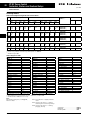
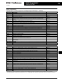
Electrical Switching Operation Charts
22
18.5
15
11
7.5
5.5
4
3
2.2
AC-3/400V
A
58
43
36
30
23
16
12
8.8 XTMC 9A
6.5 XTMC 6A
5
XTMC DC Coil
1.5
3.5
1.1
2.5
XTMC AC Coil
0.8
0.55
2
1.6
0.01
kW
22
18.5
15
11
7.5
5.5
4
3
2.2
1.5
Rated operational current le 50 – 60 Hz
30
Squirrel-cage motors
Operating characteristics
Jogging, plugging, reversing
Electrical Characteristics —
Make (NO): 6x rated motor current
Breaking (NC): 6x rated motor current
Rated output of three-phase motors, 50 – 60 Hz
kW
Rated operational current le 50 – 60 Hz
Rated output of three-phase motors, 50 – 60 Hz
Squirrel-cage motors
Operating characteristics
Starting: from rest
Stopping: after attaining a full running speed
Electrical Characteristics —
Make (NO): Up to 6x rated motor current
Breaking (NC): 1x rated motor current
AC-4/400V
A
43
36
30
23
16
12
8.8
6.5 XTMC 9A
5 XTMC 6A
3.5
1.1
2.5
0.8
2
0.55
1.6
0.37
1.2
0.25
0.8
0.01
0.04
0.1
0.4 0.75
2
4 6 10
0.02
0.06
0.2
0.6 1
3 5 8
Component lifespan (millions of operations)
0.03 0.06
0.2
0.4
1
3 5 8
0.02 0.04
0.1
0.3
0.6
2
4 6 10
Component lifespan (millions of operations)
Figure 16. Extreme Switching Duty — AC-4/400V
Figure 15. Normal Switching Duty — AC-3/400V
CAT.02.02.S.K.CD
For more information visit: www.EatonElectrical.ca
XT IEC Power Control
Miniature Controls
June 2005
1400
1000
700
500
350
275
Short-time current
Technical Data and Specifications
Breaking current
26
AC-1/400V
A
700
AC-1/400V
500
400
300
160
100
200
55
35
100
150
70
20 XTMC 9A
XTMC 9A
50
40
10
7
5
4
3
2
30
20
15
1
0.1
0.2 0.3
0.5 0.7
1
2
3
5
7
10
Seconds 2
3
5
7 10
20 30 50 70 100 200 300 500 700 900
Duration of load
Component lifespan (millions of operations)
Figure 17. Switching Duty for Non-motor Loads, 3- & 4-Pole —
AC-1/400V
1 min
3 min
10 min
5 min
15 min
Figure 18. Short Time Loading, 3-Pole — AC-1/400V (time interval
between two loading cycles: 15 minutes)
For more information visit: www.EatonElectrical.ca
CAT.02.02.S.K.CD
XT IEC Power Control
Miniature Controls
27
June 2005
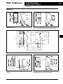
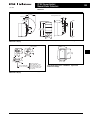
Dimensions
Dimensions
D
M4
62.5
[2.46]
58
50
[1.97]
45
[1.77]
35
[1.38]
45
[1.77]
52
[2.05]
Figure 23. XTMCXRSA, XTMCXVSA Mini Suppressors — Approximate
Dimensions in mm [in]
D1
43
[1.69]
Figure 19. Non-reversing Mini Contactor
45
[1.77]
58
[2.28]
Table 41. Mini Contactor
XTMC
XTMCC
D
52 [2.05]
54 [2.13]
D1
83 [3.27]
86 [3.39]
45
[1.77]
69
[2.72]
Figure 24. XTMCXTSA Mini Sealable Shroud — Approximate
Dimensions in mm [in]
61
[2.40]
58
[2.28]
108
[4.25]
63
[2.48]
83
[3.27]
180
[7.09]
58
[2.28]
Figure 20. Star-Delta Starter Combinations
90
[3.54]
61
[2.40]
Figure 25. XTMCXML Mechanical Interlock — Approximate
Dimensions in mm [in]
108
[4.25]
90
[3.54]
94
[3.70]
Figure 21. Reversing Mini Contactor
5.5
[.22]
106
49
[4.17] [1.93]
32
[1.26]
45
[1.77]
58
[2.28]
≥ 5 [.20]
Figure 22. Non-reversing Mini Contactor with Overload Relay
CAT.02.02.S.K.CD
94
[3.70]
For more information visit: www.EatonElectrical.ca
28
XT IEC Power Control
Contactors, Starters and Overload Relays
June 2005
Product Family Overview
Features and Benefits
Contents
Description
Catalog Number
Selection . . . . . . . . . . . . . . . .
Product Selection
Non-reversing Contactors . . .
Reversing Contactors . . . . . . .
Non-reversing Starters . . . . . .
Reversing Starters . . . . . . . . . .
Star-Delta (Wye-Delta)
Starters. . . . . . . . . . . . . . . . . .
Overload Relays. . . . . . . . . . . .
Accessories . . . . . . . . . . . . . . .
Renewal Parts . . . . . . . . . . . . .
Technical Data and
Specifications . . . . . . . . . . . .
Dimensions . . . . . . . . . . . . . . .
Page
■
29
■
■
30
33
35
38
■
■
■
40
44
47
53
54
78
■
■
■
■
■
■
■
AC control from 12V to 600V
50/60 Hz
DC control from 12V to 220V
Available with screw or spring cage
terminals
Reversing or non-reversing contactors and starters
AC-3 contactor ratings to 1000A and
AC-1 contactor ratings to 2000A
Non-reversing starters to 650A
Panel or DIN rail mounting to 65A
IP20 finger and back-of-hand proof
Large ambient temperature range,
-25 to 50°C [-13 to 122°F]
AC and DC controlled contactors in
the same compact frame
Low power consumption DC coils
Built-in NO or NC auxiliary contacts
to 32A
Plug-in accessories for reduced
installation time
Standards and Certifications
■
■
■
■
■
■
IEC EN 60947
CE Approved
UL
CSA
CCC (pending)
ATEX (pending)
XT Family of Contactors
Product Description
Eaton’s new line of XT Contactors and
Starters includes non-reversing and
reversing contactors, overload relays
and a variety of related accessories.
Because XT meets IEC, UL, CSA,
CCC and CE standards, it is the perfect
product solution for IEC applications
all over the world. The compact, space
saving, and easy to install XT line of IEC
contactors and starters is the efficient
and effective solution for customer
applications from 7A to 2000A.
Instructional Leaflets
Pub51210 Inside of Packaging 7 – 15A
B-Frame XTCE, XTCEC and
XTCF Contactors and
Accessories
Pub51232 18 – 32A C-Frame XTCE
Contactors and Auxiliary
Contacts
Pub51216 40 – 65A D-Frame XTCE
Contactors and Auxiliary
Contacts
Pub51203 185 – 500A L-M Frame XTCE
Contactors and Auxiliary
Contacts
Pub51215 S-Series 185 – 500A L-M
Frame XTCE Contactors and
Auxiliary Contacts
Pub51204 580 – 1000A N-Frame XTCE
Contactors and Auxiliary
Contacts
Pub51209 1400 – 2000A P-R Frame
XTCE Contactors and
Auxiliary Contacts
Pub51213 7 – 150A B-G Frame XTAE
Non-reversing and XTAR
Reversing Starters
Pub51217 XTCEXFA and XTCEXSA
Front and Side Mount
Auxiliary Contacts from
40 – 150A D-G Frame XTCE
Contactors
Pub51212 XTCEXML Mechanical
Interlock for 7 – 150A B-G
Frame XTCE Contactors
Pub51214 XTCEXRL Reversing Link
Kits for 18 – 32A C-Frame
XTCE Contactors
Pub51218 XTCEXTL Lug Kits for 500 –
820A M-N Frame XTCE
Contactors
Pub51219 XTCEXRLB and XTCEXSDLB
Reversing and Star-Delta
(Wye-Delta) Link Kits for
7 – 12A B-Frame XTCE
Contactors
Pub51211 Inside of Packaging 18 – 32A
C-Frame XTCE and XTCEC
Contactors and Accessories
Pub51205 Accessories for 185 – 500A
L-M Frame XTCE Contactors
Pub51221 Inside of Packaging XTOB
D-Frame Overload Relays
Pub51213 Renewal Parts — Coils for
18 – 32A C-Frame XTCE
Contactors
Pub51222 Inside of Packaging XTOB
B-C Frame Overload Relays
Pub51237 7 – 12A B-Frame XTCE
Contactors and Auxiliary
Contacts
For more information visit: www.EatonElectrical.ca
Pub51207 Replacement DC Coils
Pub51186 Renewal Parts — Coils for
40 – 65A D-Frame XTCE
Contactors
CAT.02.02.S.K.CD
XT IEC Power Control
Contactors, Starters and Overload Relays
June 2005
Catalog Number Selection
Catalog Number Selection
Table 42. XT IEC Contactors & Starters — Catalog Numbering System
XT CE C 007 B 01 AD P16
Designation
Maximum Overload Rating
XT = XT Line of IEC Control
XTAE, XTAS and XTAR Starters Only
Frame B
P16 = 0.1 – 0.16A
P24 = 0.16 – 0.24A
P40 = 0.24 – 0.4A
P60 = 0.4 – 0.6A
001 = 0.6 – 1A
1P6 = 1.0 – 1.6A
2P4 = 1.6 – 2.4A
004 = 2.4 – 4A
006 = 4 – 6A
010 = 6 – 10A
012 = 9 – 12A
016 = 12 – 16A
Type
CE =
CS =
CF =
CR =
CC =
AE =
AS =
AR =
3-Pole FVNR IEC Contactor
3-Pole FVNR S Series IEC Contactor
4-Pole FVNR IEC Contactor
3-Pole FVR IEC Contactor
IEC Capacitor Contactor
FVNR IEC Starter
FVNR S-Series IEC Starter
FVR IEC Starter
Terminations
Frame C
P16 = 0.1 – 0.16A
P24 = 0.16 – 0.24A
P40 = 0.24 – 0.4A
P60 = 0.4 – 0.6A
001 = 0.6 – 1A
1P6 = 1.0 – 1.6A
2P4 = 1.6 – 2.4A
004 = 2.4 – 4A
006 = 4 – 6A
010 = 6 – 10A
016 = 10 – 16A
024 = 16 – 24A
032 = 24 – 32A
Blank = Screw Terminals
(6 – 65A); 5 mm (80 – 150A);
No Lugs (185 – 2000A)
C = Spring Cage Terminals
(6 – 32A); Spring Cage Coil
Terminals Only (185 – 2000A)
Current Ratings,
AC-3
Frame Size
Designation
007 =
009 =
012 =
015 =
7A
9A
12A
15A
B=
45 mm
018 =
025 =
032 =
18A
25A
32A
C=
45 mm
040 =
050 =
065 =
40A
50A
65A
D = 55 mm
080 =
095 =
80A
95A
F=
01 = 1NC
10 = 1NO
Frame D
010 = 6 – 10A
016 = 12 – 16A
024 = 16 – 24A
040 = 24 – 40A
057 = 40 – 57A
065 = 50 – 65A
00 = 0NO-0NC
Frame F
035 = 25 – 35A
050 = 35 – 50A
070 = 50 – 70A
100 = 70 – 100A
90 mm
115 = 115A
150 = 150A
G = 90 mm
185 = 185A
225 = 225A
L=
250 =
300 =
400 =
500 =
250A
300A
400A
500A
M = 160 mm
580 =
650 =
750 =
820 =
C10 =
580A
650A
750A
820A
1000A
N = 250 mm
Coil Codes
140 mm
C14 = 1400A, AC-1 P =
260 mm
C20 = 2000A, AC-1 R =
515 mm
CAT.02.02.S.K.CD
Auxiliary Contact
22 = 2NO-2NC
See Page 32.
For more information visit: www.EatonElectrical.ca
Frame G
035 = 25 – 35A
050 = 35 – 50A
070 = 50 – 70A
100 = 70 – 100A
125 = 95 – 125A
150 = 120 – 150A
Frame L
070 = 50 – 70A
100 = 70 – 100A
125 = 95 – 125A
160 = 120 – 160A
220 = 160 – 220A
250 = 200 – 250A
Frame M
063 = 42 – 63A
090 = 60 – 90A
125 = 85 – 125A
160 = 110 – 160A
240 = 160 – 240A
290 = 190 – 290A
400 = 270 – 400A
540 = 360 – 540A
Frame N
063 = 42 – 63A
090 = 60 – 90A
125 = 85 – 125A
160 = 110 – 160A
240 = 160 – 240A
290 = 190 – 290A
400 = 270 – 400A
540 = 360 – 540A
630 = 420 – 630A
29
XT IEC Power Control
Contactors, Starters and Overload Relays
30
June 2005
Product Selection
Product Selection
Non-reversing Contactors
Table 43. Full Voltage Non-reversing 3-Pole Contactors
Ie (A)
AC-3
AC-1
Maximum kW
Maximum 3-Phase Motor Rating
Ratings AC-3
3-Phase Motors 50 – 60 Hz
1-Phase hp Ratings
3-Phase hp Ratings
220/ 380/ 415V 660/
1000V 115V 200V 230V 200V 230V 460V
230V 400V
690V Aux.
Contacts
575V
Catalog
Number —
Screw
Terminals
Price
AC
Coil
DC
Coil
Frame B
7
7
9
9
20
20
20
20
2.2
2.2
2.5
2.5
3
3
4
4
4
4
5.5
5.5
3.5
3.5
4.5
4.5
—
—
—
—
12
12
15.5
15.5
20
20
20
20
3.5
3.5
4
4
5.5
5.5
7.5
7.5
7
7
8
8
6.5
6.5
7
7
—
—
—
—
35
35
40
40
40
40
5
5
7.5
7.5
10
10
7.5
7.5
11
11
15
15
10
10
14.5
14.5
18
18
11
11
14
14
17
17
50
60
72
12.5
15.5
20
18.5
22
30
24
30
39
23
30
35
110
110
25
30
37
45
48
57
63
75
45
55
160
160
37
48
55
75
70
91
105
125
66
80
10
15
1/4
1/4
1/2
1/2
3/4
3/4
1
1
1
1
1-1/2
1-1/2
1-1/2
1-1/2
3
3
2
2
3
3
3
3
5
5
1
1
1
1
2
2
2
2
2
2
3
3
3
3
5
5
3
3
5
5
—
—
—
—
—
—
2
2
2
2
3
3
2
2
3
3
5
5
3
3
5
5
5
5
—
—
—
3
3
5
10 10 10 10 5
5
7-1/2
7-1/2
10
10
10
10
1NO
1NC
1NO
1NC
1NO
1NC
1NO
1NC
XTCE007B10_
XTCE007B01_
XTCE009B10_
XTCE009B01_
XTCE012B10_
XTCE012B01_
XTCE015B10_
XTCE015B01_
10 10 15
15
20
20
15
15
20
20
25
25
1NO
1NC
1NO
1NC
1NO
1NC
XTCE018C10_
XTCE018C01_
XTCE025C10_
XTCE025C01_
XTCE032C10_
XTCE032C01_
15
20
25
30
40
50
40
50
60
—
—
—
XTCE040D00_
XTCE050D00_
XTCE065D00_
Frame C
18
18
25
25
32
32
5
5
5
5
7-1/2 7-1/2
7-1/2 7-1/2
10
10
10
10
Frame D
40
50
65
5
7-1/2 10
7-1/2 10
15
10
15
20
Frame F
80
95
15
15
25
25
30
40
60
75
75
100
—
—
XTCE080F00_ XTCE095F00_ 25
25
25
30
40
40
50
60
100
125
125
150
—
—
XTCE115G00_ XTCE150G00_ 7-1/2 15
7-1/2 15
Frame G
115
150
Frame L
185
225
250
275
315
350
55
70
75
90
110
132
110
132
148
175
215
240
108
108
108
—
—
—
—
—
—
—
—
—
50
60
75
60
75
100
125
150
200
150
200
250
2NO-2NC XTCE185L22_
2NO-2NC XTCE225L22_
2NO-2NC XTCE250L22_
400
500
700
90
125
155
160
200
250
180
240
300
286
344
344
132
132
132
—
—
—
—
—
—
—
—
—
100
125
150
125
150
200
250
300
400
300
400
500
2NO-2NC XTCE300M22_
2NO-2NC XTCE400M22_
2NO-2NC XTCE500M22_
800
850
900
1000
1000
185
205
240
260
315
315
355
400
450
560
348
390
455
500
610
560
630
720
750
1000
600
600
800
800
1000
—
—
—
—
—
—
—
—
—
—
—
—
—
—
—
200
200
250
290
—
200
250
300
350
—
400
500
600
700
—
600
600
700
860
—
2NO-2NC
2NO-2NC
2NO-2NC
2NO-2NC
2NO-2NC
1400 —
—
—
—
—
—
—
—
—
—
—
—
2NO-2NC XTCEC14P22_ 2000 —
—
—
—
—
—
—
—
—
—
—
—
2NO-2NC XTCEC20R22_ Frame M
300
400
500
Frame N
580
650
750
820
1000
XTCE580N22_ XTCE650N22_ XTCE750N22_ XTCE820N22_ XTCEC10N22_ Frame P
—
Frame R
—
Underscore (_) indicates magnet coil suffix required. See Table 48.
7 – 150A DC operated contactors have an integrated suppressor. 185 – 2000A AC and DC contactors have an integrated suppressor.
For Spring Cage Terminals, insert C after the fourth digit of the Catalog Number. Example: XTCEC007B10A. For 7 – 15A XTCEC Contactors, the power,
auxiliary and coil terminals are spring cage. For 18 – 32A XTCEC Contactors, the auxiliary and coil terminals are spring cage. For 40 – 150A XTCEC
Contactors, the coil terminals only are spring cage. 185 – 2000A Contactors are available with screw terminals only.
When operating the 580 – 2000A XTCE contactors with frequency inverters, the suppressor on the load side must be removed. The load side
suppressor must also be removed when performing a high-voltage test.
Available September 2005.
AC-1 Ratings Only.
For 185 – 2000A Contactors at 660/690V or 1000V: Do not reverse directly.
For electrical life contactor application data see Table 45.
Coil Voltage Chart . . . . . . . . . . . . . . . . . . . .
Accessories . . . . . . . . . . . . . . . . . . . . . . . . .
Dimensions . . . . . . . . . . . . . . . . . . . . . . . . .
Contact Sequence (Circuit Symbols) . . .
Discount Symbol . . . . . . . . . . . . . . . . . . . . .
For more information visit: www.EatonElectrical.ca
Page 32
Page 47
Page 78
Page 31
MC7
CAT.02.02.S.K.CD
XT IEC Power Control
Contactors, Starters and Overload Relays
31
June 2005
Product Selection
Frame B
Frame C
Frame D
Frame L
Frame F – G
Frame N
Frame P
Frame R
Table 44. Full Voltage 3-Pole Non-reversing S-Series Contactors — AC Coils Only
Ie (A)
AC-3
AC-1
Maximum kW
Ratings AC-3
3-Phase Motors 50 – 60 Hz
220/
380/
415V 660/
230V 400V
690V Maximum 3-Phase Motor Rating
1000V 1-Phase hp Ratings
115V
230V
Auxiliary
Contacts
3-Phase hp Ratings
200V 230V 460V
575V
Catalog
Number —
Screw
Terminals
Price
AC
Coil
Frame L
185
225
250
337
386
429
55
70
75
90
110
132
110
132
148
175
215
240
108
108
108
—
—
—
—
—
—
50
60
75
60
75
100
125
150
200
150
200
250
2NO-2NC
2NO-2NC
2NO-2NC
XTCS185L22_
XTCS225L22_
XTCS250L22_
90
125
155
160
200
250
180
240
300
286
344
344
132
132
132
—
—
—
—
—
—
100
125
150
125
150
200
250
300
400
300
400
500
2NO-2NC
2NO-2NC
2NO-2NC
XTCS300M22_
XTCS400M22_
XTCS500M22_
Frame M
300
400
500
490
612
857
Underscore (_) indicates magnet coil suffix required. See Table 48.
7 – 150A DC operated contactors have an integrated suppressor. 185 – 2000A AC and DC contactors have an integrated suppressor.
For Spring Cage Terminals, insert C after the fourth digit of the Catalog Number. Example: XTCEC007B10A. For 7 – 15A XTCEC Contactors, the power,
auxiliary and coil terminals are spring cage. For 18 – 32A XTCEC Contactors, the auxiliary and coil terminals are spring cage. For 40 – 150A XTCEC
Contactors, the coil terminals only are spring cage. 185 – 2000A Contactors are available with screw terminals only.
For 185 – 2000A Contactors at 660/690V or 1000V: Do not reverse directly.
Notes:
The 7 – 32A XTCE Contactors have positively driven contacts
between the integrated auxiliary contact and the auxiliary contact
module as well as within the auxiliary contact modules.
The 40 – 65A XTCE Contactors have positively driven contacts within
the auxiliary contact module. 6 auxiliary contacts are possible with a
combination of side mounted and front mount auxiliary contacts.
Table 45. Contactor Application Data Catalog Prefix
AC-3
Electrical Life
(Operations)
XTCE012B
XTCE015B
XTCE018C
12A
15A
18A
1 million
1.2 million
2 million
See Figure 37 on Page 76 for Electrical Life Curves.
IEC Utilization Categories, see Page 178, Reference Data.
AC-1: Non-inductive or slightly inductive loads.
AC-3: Squirrel-cage motors — starting, switching of motors during
running.
AC-4: Squirrel-cage motors — starting, plugging, inching.
Coil Voltage Chart . . . . . . . . . . . . . . . . . . . .
Accessories . . . . . . . . . . . . . . . . . . . . . . . . .
Dimensions . . . . . . . . . . . . . . . . . . . . . . . . .
Discount Symbol . . . . . . . . . . . . . . . . . . . . .
CAT.02.02.S.K.CD
For more information visit: www.EatonElectrical.ca
Page 32
Page 47
Page 78
MC7
XT IEC Power Control
Contactors, Starters and Overload Relays
32
June 2005
Product Selection
Table 46. Full Voltage 4-Pole Non-reversing Contactors with Screw Terminals
Ie (A)
AC-3
AC-1
Maximum kW
Ratings AC-3
3-Phase Motors 50 – 60 Hz
220/
230V
380/
400V
415V
660/
690V
Maximum 3-Phase Motor Rating
1000V
1-Phase hp
Ratings
115V 230V
Contact
Sequence
Catalog
Number 3-Phase hp Ratings
200V
230V
460V
Price
AC
Coil
DC
Coil
575V
20
A1 1 3 5 7
XTCF020B00_
A2 2 4 6 8
Underscore (_) indicates magnet coil suffix required. See Table 48.
Table 47. Full Voltage Non-reversing
3-Pole Contactors — Contact Sequence
(Circuit Symbols) — Standard Offering
Contactor
Frame
Auxiliary
Contacts
B–C
1NO
Contact
Sequence
1NC
D–G
—
L–R
2NO-2NC
IEC Utilization Categories, see Page 178,
Reference Data.
The 40 – 65A XTCE Contactors have positively
driven contacts within the auxiliary contact
module. 6 auxiliary contacts are possible with
a combination of side mounted and front
mount auxiliary contacts.
AC-4: Squirrel-cage motors — starting,
plugging, inching.
A1 1 3 5 13
A2 2 4 6 14
B–C
Notes:
The 7 – 32A XTCE Contactors have positively
driven contacts between the integrated
auxiliary contact and the auxiliary contact
module as well as within the auxiliary contact
modules.
A1 1 3 5 21
A2 2 4 6 22
AC-1: Non-inductive or slightly inductive
loads.
AC-3: Squirrel-cage motors — starting,
switching of motors during running.
A1 1 3 5
A2 2 4 6
A1 1 3 5 13 21 31 43
A2 2 4 6 14 22 32 44
Table 48. Magnet Coil Suffix
Coil Voltage
Suffix Code
Frame A – B
110V 50 Hz, 120V 60 Hz
220V 50 Hz, 240V 60 Hz
230V 50 Hz
24V 50/60 Hz
24V DC
415V 50 Hz, 480V 60 Hz
550V 50 Hz, 600V 60 Hz
208V 60 Hz
190V 50 Hz, 220V 60 Hz
240V 50 Hz, 277V 60 Hz
380V 50 Hz, 440V 60 Hz
400V 50 Hz
380V 60 Hz
12V 50/60 Hz
24V 50 Hz
42V 50 Hz, 48V 60 Hz
48V 50 Hz
120V DC
220V DC
12V DC
48V DC
Coil Voltage
Suffix Code
Frame C – F
A
B
F
T
TD C
D
E
G
H
L
N
P
R
U
W
Y
AD BD RD WD 110V 50 Hz, 120V 60 Hz
220V 50 Hz, 240V 60 Hz
230V 50 Hz
24V 50/60 Hz
24 – 27V DC
415V 50 Hz, 480V 60 Hz
550V 50 Hz, 600V 60 Hz
208V 60 Hz
190V 50 Hz, 220V 60 Hz
240V 50 Hz, 277V 60 Hz
380V 50 Hz, 440V 60 Hz
400V 50 Hz
380V 60 Hz
12V 50/60 Hz
24V 50 Hz
42V 50 Hz, 48V 60 Hz
48V 50 Hz
110 – 130V DC
200 – 240V DC
12 – 14V DC
48 – 60V DC
Coil Voltage
Suffix Code
Frame G
A
B
F
T
TD C
D
E
G
H
L
N
P
R
U
W
Y
AD BD RD WD 100 – 120V 50/60 Hz
190 – 240V 50/60 Hz
24V 50/60 Hz
24 – 27V DC
480 – 500V 50/60 Hz
380 – 440V 50/60 Hz
42 – 48V 50/60 Hz
110 – 130V DC
200 – 240V DC
48 – 60V DC
A
B
T
TD C
L
W
AD BD WD Frame L – N
110 – 250V 40 – 60 Hz/DC
250 – 500V 40 – 60 Hz/DC
48 – 110V 40 – 60 Hz/DC
24 – 48V DC
A
C
Y TD Frame L – N, S-Series
110 – 120V 50/60 Hz
220 – 240V 50/60 Hz
A
B
Frame P – R
220 – 250V 50 – 60 Hz/DC
B
For indicated coils, price adder of 10% must be applied to the contactor list price in Tables 43 – 46.
With DC Operation: Integrated diode-resistor combination, coil rating 2.6W.
Available October 2005, Frame C – D only.
Discount Symbol . . . . . . . . . . . . . . . . . . . . . MC7
For more information visit: www.EatonElectrical.ca
CAT.02.02.S.K.CD
XT IEC Power Control
Contactors, Starters and Overload Relays
33
June 2005
Product Selection
Reversing Contactors
Frame B XTCR
Reversing Contactor
Table 49. Full Voltage Reversing Contactors with Screw Terminals
Ie (A)
Maximum kW Ratings AC-3
Maximum 3-Phase Motor Rating
AC-3
3-Phase Motors 50 – 60 Hz
220/
380/
415V 660/
230V 400V
690V
1-Phase hp Ratings
115V
230V
3-Phase hp Ratings
200V
230V
460V
Spare Auxiliary
Contacts
K1M
K2M
Catalog
Number Price
AC Coil
DC Coil
575V
Frame B
7
9
12
2.2
3
2.5
4
3.5
5.5
4
5.5
7
3.5
1/4
4.5
1
1/2
6.5
1-1/2
1/2
2
1-1/2
2
3
2
3
3
3
5
7-1/2
5
7-1/2
10
63
63
64
64
63
63
64
64
63
63
64
64
63
63
64
64
63
63
64
64
63
63
64
64
XTCR007B21_
XTCR009B21_
XTCR012B21_
Frame C
18
25
32
5
7.5
10
7.5
11
15
8
14.5
18
11
14
17
2
3
2
5
3
5
5
7-1/2
10
5
7-1/2
10
10
15
20
15
20
25
XTCR018C21_
XTCR025C21_
XTCR032C21_
Frame D
40
50
65
12.5
15.5
20
18.5
22
30
24
30
39
23
30
35
3
3
5
7-1/2
10
15
10
15
20
15
20
25
30
40
50
40
50
60
—
—
—
—
—
—
XTCR040D11_
XTCR050D11_
XTCR065D11_
25
30
37
45
48
57
63
75
7-1/2
7-1/2
15
15
25
25
30
40
60
75
75
100
—
—
—
—
XTCR080F11_ XTCR095F11_ 37
48
55
75
70
91
105
125
25
30
40
40
50
60
100
125
125
150
—
—
—
—
XTCR115G11_ XTCR150G11_ Frame F
80
95
Frame G
115
150
10
15
Underscore (_) indicates magnet coil suffix required. See Table 50.
The factory assembled reversing contactor for the 7 – 32A devices includes: (2) XTCE…01_ Contactors, (2) XTCEXFAC20 2NO Seq. A Front Mount
Auxiliary Contacts, (1) XTCEXRL Reversing Link Kit and (1) XTCEXML_ Mechanical Interlock. The factory assembled reversing contactor for the 40 –
150A devices includes: (2) XTCE…00_ Contactors and (2) XTCEXFBG11 1NO-1NC Seq. B Front Mount Auxiliary Contacts and (1) XTCEXML_
Mechanical Interlock.
Available September 2005.
Note:
IEC Utilization Categories, see Page 178,
Reference Data.
AC-1: Non-inductive or slightly inductive
loads.
AC-3: Squirrel-cage motors — starting,
switching of motors during running.
AC-4: Squirrel-cage motors — starting,
plugging, inching.
CAT.02.02.S.K.CD
Coil Voltage Chart . . . . . . . . . . . . . . . . . . . . .
Accessories . . . . . . . . . . . . . . . . . . . . . . . . .
Dimensions . . . . . . . . . . . . . . . . . . . . . . . . . .
Discount Symbol . . . . . . . . . . . . . . . . . . . . .
For more information visit: www.EatonElectrical.ca
Page 34
Page 47
Page 78
MC7
XT IEC Power Control
Contactors, Starters and Overload Relays
34
June 2005
Product Selection
Table 50. Magnet Coil Suffix
Coil Voltage
Suffix Code
Coil Voltage
Frame A – B
110V 50 Hz, 120V 60 Hz
220V 50 Hz, 240V 60 Hz
230V 50 Hz
24V 50/60 Hz
24V DC
415V 50 Hz, 480V 60 Hz
550V 50 Hz, 600V 60 Hz
208V 60 Hz
190V 50 Hz, 220V 60 Hz
240V 50 Hz, 277V 60 Hz
380V 50 Hz, 440V 60 Hz
400V 50 Hz
380V 60 Hz
12V 50/60 Hz
24V 50 Hz
42V 50 Hz, 48V 60 Hz
48V 50 Hz
120V DC
220V DC
12V DC
48V DC
Suffix Code
Frame C – F
A
B
F
T
TD C
D
E
G
H
L
N
P
R
U
W
Y
AD BD RD WD Coil Voltage
Suffix Code
Frame G
110V 50 Hz, 120V 60 Hz
220V 50 Hz, 240V 60 Hz
230V 50 Hz
24V 50/60 Hz
24 – 27V DC
415V 50 Hz, 480V 60 Hz
550V 50 Hz, 600V 60 Hz
208V 60 Hz
190V 50 Hz, 220V 60 Hz
240V 50 Hz, 277V 60 Hz
380V 50 Hz, 440V 60 Hz
400V 50 Hz
380V 60 Hz
12V 50/60 Hz
24V 50 Hz
42V 50 Hz, 48V 60 Hz
48V 50 Hz
110 – 130V DC
200 – 240V DC
12 – 14V DC
48 – 60V DC
A
B
F
T
TD C
D
E
G
H
L
N
P
R
U
W
Y
AD BD RD WD 100 – 120V 50/60 Hz
190 – 240V 50/60 Hz
24V 50/60 Hz
24 – 27V DC
480 – 500V 50/60 Hz
380 – 440V 50/60 Hz
42 – 48V 50/60 Hz
110 – 130V DC
200 – 240V DC
48 – 60V DC
A
B
T
TD C
L
W
AD BD WD Frame L – N
110 – 250V 40 – 60 Hz/DC
250 – 500V 40 – 60 Hz/DC
48 – 110V 40 – 60 Hz/DC
24 – 48V DC
A
C
Y TD Frame L – N, S-Series
110 – 120V 50/60 Hz
220 – 240V 50/60 Hz
A
B
Frame P – R
220 – 250V 50 – 60 Hz/DC
B
For indicated coils, price adder of 10% must be applied to the contactor list price in Table 49.
With DC Operation: Integrated diode-resistor combination, coil rating 2.6W.
Available October 2005, Frame C – D only.
0
21
22
0
22
21
21
22
13
14
I
14
13
54
54
K1M
K2M 53
53
22
22
K2M 21
K1M 21
A1
A1
K1M
K2M
II
A2
7 – 32A
A2
21
22
22
21
22
21
14
13
I
14
13
14
14
K2M
K1M
13
13
22
K2M
K1M 22
21
21
A1
A1
K1M
K2M
A2
A2
(-)N
1 3 5
II
40 – 150A
K1M
13 5
2 4 6 K2M 2 4 6
M1
U V W
M
3
7 – 65A with
Mechanical Interlock
Figure 26. 7 – 150A XTCR Reversing Contactor Wiring Diagram
Accessories . . . . . . . . . . . . . . . . . . . . . . . . . Page 47
Dimensions . . . . . . . . . . . . . . . . . . . . . . . . . Page 78
Discount Symbol . . . . . . . . . . . . . . . . . . . . . MC7
For more information visit: www.EatonElectrical.ca
CAT.02.02.S.K.CD
XT IEC Power Control
Contactors, Starters and Overload Relays
35
June 2005
Product Selection
Non-reversing Starters
Frame C XTAE
Non-reversing Starter
Table 51. Full Voltage Non-reversing 3-Pole Starters Ie (A)
Maximum kW Ratings AC-3
AC-3 AC-1 3-Phase Motors 50 – 60 Hz
220/ 380/ 415V 660/
230V 400V
690V
Maximum 3-Phase Motor Rating
1-Phase hp Ratings
1000V 115V
230V
Auxiliary
Contacts
3-Phase hp Ratings
200V
230V
460V
Catalog
Number Price
AC Coil DC Coil
575V
Frame B
7
7
9
9
20
20
20
20
2.2
2.2
2.5
2.5
3
3
4
4
4
4
5.5
5.5
3.5
3.5
4.5
4.5
—
—
—
—
12
12
15.5
15.5
20
20
20
20
3.5
3.5
4
4
5.5
5.5
7.5
7.5
7
7
8
8
6.5
6.5
7
7
—
—
—
—
35
35
40
40
40
40
5
5
7.5
7.5
10
10
7.5
7.5
11
11
15
15
10
10
14.5
14.5
18
18
11
11
14
14
17
17
50
60
72
12.5
15.5
20
18.5
22
30
24
30
39
23
30
35
25
30
37
45
48
57
63
75
45
55
160
160
37
48
55
75
70
91
105
125
66
80
275
315
350
55
70
75
90
110
132
110
132
148
175
215
240
90
125
155
160
200
250
180
240
300
185
205
315
355
348
390
1/4
1/4
1/2
1/2
1
1
1-1/2
1-1/2
1-1/2
1-1/2
3
3
2
2
3
3
3
3
5
5
1
1
1
1
2
2
3
3
3
3
5
5
3
3
5
5
—
—
—
—
—
—
2
2
2
2
3
3
3
3
5
5
5
5
—
—
—
3
3
5
7-1/2
7-1/2
10 10 10 10 5
5
7-1/2
7-1/2
10
10
10
10
1NO
1NC
1NO
1NC
1NO
1NC
1NO
1NC
XTAE007B10_ _
XTAE007B01_ _
XTAE009B10_ _
XTAE009B01_ _
XTAE012B10_ _
XTAE012B01_ _
XTAE015B10_ _
XTAE015B01_ _
Frame C
18
18
25
25
32
32
5
5
7-1/2
7-1/2
10
10
5
5
7-1/2
7-1/2
10
10
10 10 15
15
20
20
15
15
20
20
25
25
1NO
1NC
1NO
1NC
1NO
1NC
XTAE018C10_ _
XTAE018C01_ _
XTAE025C10_ _
XTAE025C01_ _
XTAE032C10_ _
XTAE032C01_ _
7-1/2
10
15
10
15
20
15
20
25
30
40
50
40
50
60
—
—
—
XTAE040D00_ _
XTAE050D00_ _
XTAE065D00_ _
15
15
25
25
30
40
60
75
75
100
—
—
XTAE080F00_ _
XTAE095F00_ _
10
15
25
30
40
40
50
60
100
125
125
150
—
—
XTAE115G00_ _
XTAE150G00_ _
108
108
108
—
—
—
—
—
—
50
60
75
60
75
100
125
150
200
150
200
250
2NO-2NC
2NO-2NC
2NO-2NC
XTAE185L22_ _
XTAE225L22_ _
XTAE250L22_ _
286
344
344
132
132
132
—
—
—
—
—
—
100
125
150
125
150
200
250
300
400
300
400
500
2NO-2NC
2NO-2NC
2NO-2NC
XTAE300M22_ _
XTAE400M22_ _
XTAE500M22_ _
560
630
600
600
—
—
—
—
200
200
200
250
400
500
600
600
2NO-2NC
2NO-2NC
XTAE580N22_ _
XTAE650N22_ _
Frame D
40
50
65
Frame F
80
95
110
110
Frame G
115
150
Frame L
185
225
250
Frame M
300
400
500
400
500
700
Frame N
580
650
800
850
Underscore (_) indicates magnet coil suffix required. See Table 53.
Underscore (_) indicates overload relay suffix required. See Table 55.
Available August 2005.
For electrical life contactor application data see Table 54.
Notes:
IEC Utilization Categories, see Page 178,
Reference Data.
AC-3: Squirrel-cage motors — starting,
switching of motors during running.
AC-1: Non-inductive or slightly inductive
loads.
AC-4: Squirrel-cage motors — starting,
plugging, inching.
CAT.02.02.S.K.CD
For more information visit: www.EatonElectrical.ca
Coil Voltage Chart . . . . . . . . . . . . . . . . . . . . .
Accessories . . . . . . . . . . . . . . . . . . . . . . . . .
Dimensions . . . . . . . . . . . . . . . . . . . . . . . . . .
Discount Symbol . . . . . . . . . . . . . . . . . . . . .
Page 36
Page 47
Page 78
MC7
XT IEC Power Control
Contactors, Starters and Overload Relays
36
June 2005
Product Selection
Table 52. Full Voltage Non-reversing S-Series 3-Pole Starters Ie (A)
AC-3
Maximum kW Ratings AC-3
AC-1
3-Phase Motors 50 – 60 Hz
220/
380/
415V 660/
230V 400V
690V
Maximum 3-Phase Motor Rating
1000V
1-Phase hp Ratings
115V
230V
Catalog
Number 3-Phase hp Ratings
200V 230V 460V
Price
AC Coil
DC Coil
575V
Frame L
185
225
250
337
386
429
55
70
75
90
110
132
110
132
148
175
215
240
108
108
108
—
—
—
—
—
—
50
60
75
60
75
100
125
150
200
150
200
250
XTAS185L00_ _
XTAS225L00_ _
XTAS250L00_ _
490
612
857
90
125
155
160
200
250
180
240
300
286
344
344
132
132
132
—
—
—
—
—
—
100
125
150
125
150
200
250
300
400
300
400
500
XTAS300M00_ _
XTAS400M00_ _
XTAS500M00_ _
Frame M
300
400
500
Underscore (_) indicates magnet coil suffix required. See Table 53.
Underscore (_) indicates overload relay suffix required. See Table 55.
Available August 2005.
Table 53. Magnet Coil Suffix
Coil Voltage
Suffix Code
Frame A – B
110V 50 Hz, 120V 60 Hz
220V 50 Hz, 240V 60 Hz
230V 50 Hz
24V 50/60 Hz
24V DC
415V 50 Hz, 480V 60 Hz
550V 50 Hz, 600V 60 Hz
208V 60 Hz
190V 50 Hz, 220V 60 Hz
240V 50 Hz, 277V 60 Hz
380V 50 Hz, 440V 60 Hz
400V 50 Hz
380V 60 Hz
12V 50/60 Hz
24V 50 Hz
42V 50 Hz, 48V 60 Hz
48V 50 Hz
120V DC
220V DC
12V DC
48V DC
Coil Voltage
Suffix Code
Frame C – F
A
B
F
T
TD C
D
E
G
H
L
N
P
R
U
W
Y
AD BD RD WD Coil Voltage
Suffix Code
Frame G
110V 50 Hz, 120V 60 Hz
220V 50 Hz, 240V 60 Hz
230V 50 Hz
24V 50/60 Hz
24 – 27V DC
415V 50 Hz, 480V 60 Hz
550V 50 Hz, 600V 60 Hz
208V 60 Hz
190V 50 Hz, 220V 60 Hz
240V 50 Hz, 277V 60 Hz
380V 50 Hz, 440V 60 Hz
400V 50 Hz
380V 60 Hz
12V 50/60 Hz
24V 50 Hz
42V 50 Hz, 48V 60 Hz
48V 50 Hz
110 – 130V DC
200 – 240V DC
12 – 14V DC
48 – 60V DC
A
B
F
T
TD C
D
E
G
H
L
N
P
R
U
W
Y
AD BD RD WD 100 – 120V 50/60 Hz
190 – 240V 50/60 Hz
24V 50/60 Hz
24 – 27V DC
480 – 500V 50/60 Hz
380 – 440V 50/60 Hz
42 – 48V 50/60 Hz
110 – 130V DC
200 – 240V DC
48 – 60V DC
A
B
T
TD C
L
W
AD BD WD Frame L – N
110 – 250V 40 – 60 Hz/DC
250 – 500V 40 – 60 Hz/DC
48 – 110V 40 – 60 Hz/DC
24 – 48V DC
A
C
Y TD Frame L – N, S-Series
110 – 120V 50/60 Hz
220 – 240V 50/60 Hz
A
B
Frame P – R
220 – 250V 50 – 60 Hz/DC
B
For indicated coils, price adder of 10% must be applied to the contactor list price in Tables 51 and 52.
With DC Operation: Integrated diode-resistor combination, coil rating 2.6W. Available October 2005, Frame C – D only.
Note:
IEC Utilization Categories, see Page 178,
Reference Data.
AC-1: Non-inductive or slightly inductive
loads.
AC-3: Squirrel-cage motors — starting,
switching of motors during running.
AC-4: Squirrel-cage motors — starting,
plugging, inching.
Table 54. Contactor Application Data Catalog Prefix
AC-3
Electrical Life
(Operations)
XTAE012B
XTAE015B
XTAE018C
12A
15A
18A
1 million
1.2 million
2 million
See Figure 37 on Page 76 for Electrical Life
Curves.
Accessories . . . . . . . . . . . . . . . . . . . . . . . . . Page 47
Dimensions . . . . . . . . . . . . . . . . . . . . . . . . . Page 78
Discount Symbol . . . . . . . . . . . . . . . . . . . . . MC7
For more information visit: www.EatonElectrical.ca
CAT.02.02.S.K.CD
XT IEC Power Control
Contactors, Starters and Overload Relays
37
June 2005
Product Selection
Table 55. Overload Relay Suffix
Motor Full
Load
Amperes
Suffix
Code
For use with
Contactor
Amp Range
Overload Relay
Catalog
Number
Frame B
P16
P24
P40
P60
7 – 15A
7 – 15A
7 – 15A
7 – 15A
XTOBP16BC1
XTOBP24BC1
XTOBP40BC1
XTOBP60BC1
0.6 – 1
1 – 1.6
1.6 – 2.4
2.4 – 4
001
1P6
2P4
004
7 – 15A
7 – 15A
7 – 15A
7 – 15A
XTOB001BC1
XTOB1P6BC1
XTOB2P4BC1
XTOB004BC1
006
010
012
016
7 – 15A
7 – 15A
9 – 15A
12 – 15A
XTOB006BC1
XTOB009BC1
XTOB012BC1
XTOB016BC1
0.1 – 0.16
0.16 – 0.24
0.24 – 0.4
0.4 – 0.6
P16
P24
P40
P60
18 – 32A
18 – 32A
18 – 32A
18 – 32A
XTOBP16CC1
XTOBP24CC1
XTOBP40CC1
XTOBP60CC1
0.6 – 1
1 – 1.6
1.6 – 2.4
2.4 – 4
001
1P6
2P4
004
18 – 32A
18 – 32A
18 – 32A
18 – 32A
XTOB001CC1
XTOB1P6CC1
XTOB2P4CC1
XTOB004CC1
006
010
016
024
032
18 – 32A
18 – 32A
18 – 32A
18 – 32A
25 – 32A
XTOB006CC1
XTOB010CC1
XTOB016CC1
XTOB024CC1
XTOB032CC1
Frame C
4–6
6 – 10
10 – 16
16 – 24
24 – 32
Suffix
Code
For use with
Contactor
Amp Range
Overload Relay
Catalog
Number
035
050
070
100
125
150
115 – 150A
115 – 150A
115 – 150A
115 – 150A
115 – 150A
150A
XTOB055GC1 XTOB050GC1 XTOB070GC1 070
100
125
185 – 250A
185 – 250A
185 – 250A
XTOB070LC1
XTOB100LC1
XTOB125LC1
160
220
250
185 – 250A
185 – 250A
225 – 250A
XTOB160LC1
XTOB220LC1
XTOB250LC1
42 – 63
60 – 90
85 – 125
110 – 160
063
090
125
160
300 – 500A
300 – 500A
300 – 500A
300 – 500A
XTOT063C3S
XTOT090C3S
XTOT125C3S
XTOT160C3S
160 – 240
190 – 290
270 – 400
360 – 540
240
290
400
540
300 – 500A
300 – 500A
300 – 500A
500A
XTOT240C3S
XTOT290C3S
XTOT400C3S
XTOT540C3S
42 – 63
60 – 90
85 – 125
110 – 160
063
090
125
160
580 – 650A
580 – 650A
580 – 650A
580 – 650A
XTOT063C3S
XTOT090C3S
XTOT125C3S
XTOT160C3S
160 – 240
190 – 290
270 – 400
360 – 540
420 – 630
240
290
400
540
630
580 – 650A
580 – 650A
580 – 650A
580 – 650A
580 – 650A
XTOT240C3S
XTOT290C3S
XTOT400C3S
XTOT540C3S
XTOT630C3S
Frame G
0.1 – 0.16
0.16 – 0.24
0.24 – 0.4
0.4 – 0.6
4–6
6 – 10
9 – 12
12 – 16
Motor Full
Load
Amperes
Frame D
6 – 10
10 – 16
16 – 24
010
016
024
40 – 65A
40 – 65A
40 – 65A
XTOB010DC1
XTOB016DC1
XTOB024DC1
24 – 40
40 – 57
50 – 65
040
057
065
40 – 65A
50 – 65A
65A
XTOB040DC1
XTOB057DC1
XTOB065DC1
035
050
070
100
80 – 95A
80 – 95A
80 – 95A
80 – 95A
XTOB055GC1 XTOB050GC1 XTOB070GC1 XTOB100GC1 25 – 35
35 – 50
50 – 70
70 – 100
95 – 125
120 – 150
Frame L
50 – 70
70 – 100
95 – 125
120 – 160
160 – 220
200 – 250
Frame M
Frame N
Frame F
25 – 35
35 – 50
50 – 70
70 – 100
Catalog Number refers to direct mount overload relay. Add an S to the end of the Catalog Number for separate mount.
CAT.02.02.S.K.CD
XTOB100GC1 XTOB125GC1 XTOB150GC1 For more information visit: www. EatonElectrical.ca
XT IEC Power Control
Contactors, Starters and Overload Relays
38
June 2005
Product Selection
Reversing Starters
Table 56. Full Voltage Reversing Starters with Screw Terminals Ie (A)
Maximum kW Ratings AC-3
Maximum 3-Phase Motor Rating
AC-3
3-Phase Motors 50 – 60 Hz
220/
380/
415V
660/
230V
400V
690V
1-Phase hp Ratings
115V
230V
Catalog
Number 3-Phase hp Ratings
200V
230V
460V
Price
AC Coil
DC Coil
575V
Frame B
7
9
12
2.2
2.5
3.5
3
4
5.5
4
5.5
7
5
7.5
10
7.5
11
15
8
14.5
18
12.5
15.5
20
18.5
22
30
25
30
37
48
3.5
4.5
6.5
1/4
1/2
1
1
1-1/2
2
11
14
17
2
2
3
3
5
5
24
30
39
23
30
35
3
3
5
37
45
48
57
63
75
7-1/2
7-1/2
55
75
70
91
105
125
1-1/2
3
3
2
3
3
3
5
10
5
7-1/2
10
XTAR007B21_ _
XTAR009B21_ _
XTAR012B21_ _
Frame C
18
25
32
5
7-1/2
10
5
7-1/2
10
10
15
20
15
20
25
XTAR018C21_ _
XTAR025C21_ _
XTAR032C21_ _
7-1/2
10
15
10
15
20
15
20
25
30
40
50
40
50
60
XTAR040D11_ _
XTAR050D11_ _
XTAR065D11_ _
15
15
25
25
30
40
60
75
75
100
XTAR080F11_ _
XTAR095F11_ _
25
30
40
40
50
60
100
125
125
150
XTAR115G11_ _
XTAR150G11_ _
Frame D
40
50
65
Frame F
80
95
Frame G
115
150
10
15
Underscore (_) indicates magnet coil suffix required. See Table 57.
Underscore (_) indicates overload relay suffix required. See Table 58.
Available August 2005.
Table 57. Magnet Coil Suffix
Coil Voltage
Suffix Code
Frame A – B
110V 50 Hz, 120V 60 Hz
220V 50 Hz, 240V 60 Hz
230V 50 Hz
24V 50/60 Hz
24V DC
415V 50 Hz, 480V 60 Hz
550V 50 Hz, 600V 60 Hz
208V 60 Hz
190V 50 Hz, 220V 60 Hz
240V 50 Hz, 277V 60 Hz
380V 50 Hz, 440V 60 Hz
400V 50 Hz
380V 60 Hz
12V 50/60 Hz
24V 50 Hz
42V 50 Hz, 48V 60 Hz
48V 50 Hz
120V DC
220V DC
12V DC
48V DC
Coil Voltage
Suffix Code
Frame C – F
A
B
F
T
TD C
D
E
G
H
L
N
P
R
U
W
Y
AD BD RD WD 110V 50 Hz, 120V 60 Hz
220V 50 Hz, 240V 60 Hz
230V 50 Hz
24V 50/60 Hz
24 – 27V DC
415V 50 Hz, 480V 60 Hz
550V 50 Hz, 600V 60 Hz
208V 60 Hz
190V 50 Hz, 220V 60 Hz
240V 50 Hz, 277V 60 Hz
380V 50 Hz, 440V 60 Hz
400V 50 Hz
380V 60 Hz
12V 50/60 Hz
24V 50 Hz
42V 50 Hz, 48V 60 Hz
48V 50 Hz
110 – 130V DC
200 – 240V DC
12 – 14V DC
48 – 60V DC
Coil Voltage
Suffix Code
Frame G
A
B
F
T
TD C
D
E
G
H
L
N
P
R
U
W
Y
AD BD RD WD 100 – 120V 50/60 Hz
190 – 240V 50/60 Hz
24V 50/60 Hz
24 – 27V DC
480 – 500V 50/60 Hz
380 – 440V 50/60 Hz
42 – 48V 50/60 Hz
110 – 130V DC
200 – 240V DC
48 – 60V DC
A
B
T
TD C
L
W
AD BD WD Frame L – N
110 – 250V 40 – 60 Hz/DC
250 – 500V 40 – 60 Hz/DC
48 – 110V 40 – 60 Hz/DC
24 – 48V DC
A
C
Y TD Frame L – N, S-Series
110 – 120V 50/60 Hz
220 – 240V 50/60 Hz
A
B
Frame P – R
220 – 250V 50 – 60 Hz/DC
B
For indicated coils, price adder of 10% must be applied to the contactor list price in Table 56.
With DC Operation: Integrated diode-resistor combination, coil rating 2.6W.
Available October 2005, Frame C – D only.
Note:
IEC Utilization Categories, see Page 178,
Reference Data.
AC-1: Non-inductive or slightly inductive
loads.
AC-3: Squirrel-cage motors — starting
switching of motors during running.
AC-4: Squirrel-cage motors — starting,
plugging, inching.
For more information visit: www.EatonElectrical.ca
Accessories . . . . . . . . . . . . . . . . . . . . . . . . . Page 47
Dimensions . . . . . . . . . . . . . . . . . . . . . . . . . Page 78
Discount Symbol . . . . . . . . . . . . . . . . . . . . . MC7
CAT.02.02.S.K.CD
XT IEC Power Control
Contactors, Starters and Overload Relays
39
June 2005
Product Selection
Table 58. Overload Relay Suffix
Motor Full
Load
Amperes
Suffix
Code
For use with
Contactor
Amp Range
Overload Relay
Catalog
Number
Frame B
P16
P24
P40
P60
7 – 15A
7 – 15A
7 – 15A
7 – 15A
XTOBP16BC1
XTOBP24BC1
XTOBP40BC1
XTOBP60BC1
0.6 – 1
1 – 1.6
1.6 – 2.4
2.4 – 4
001
1P6
2P4
004
7 – 15A
7 – 15A
7 – 15A
7 – 15A
XTOB001BC1
XTOB1P6BC1
XTOB2P4BC1
XTOB004BC1
006
010
012
016
7 – 15A
7 – 15A
9 – 15A
12 – 15A
XTOB006BC1
XTOB009BC1
XTOB012BC1
XTOB016BC1
0.1 – 0.16
0.16 – 0.24
0.24 – 0.4
0.4 – 0.6
P16
P24
P40
P60
18 – 32A
18 – 32A
18 – 32A
18 – 32A
XTOBP16CC1
XTOBP24CC1
XTOBP40CC1
XTOBP60CC1
0.6 – 1
1 – 1.6
1.6 – 2.4
2.4 – 4
001
1P6
2P4
004
18 – 32A
18 – 32A
18 – 32A
18 – 32A
XTOB001CC1
XTOB1P6CC1
XTOB2P4CC1
XTOB004CC1
006
010
016
024
032
18 – 32A
18 – 32A
18 – 32A
18 – 32A
25 – 32A
XTOB006CC1
XTOB010CC1
XTOB016CC1
XTOB024CC1
XTOB032CC1
Frame C
4–6
6 – 10
10 – 16
16 – 24
24 – 32
Suffix
Code
For use with
Contactor
Amp Range
6 – 10
10 – 16
16 – 24
010
016
024
40 – 65A
40 – 65A
40 – 65A
XTOB010DC1
XTOB016DC1
XTOB024DC1
24 – 40
40 – 57
50 – 65
040
057
065
40 – 65A
50 – 65A
65A
XTOB040DC1
XTOB057DC1
XTOB065DC1
035
050
070
100
80 – 95A
80 – 95A
80 – 95A
80 – 95A
XTOB055GC1 XTOB050GC1 XTOB070GC1 XTOB100GC1 035
050
070
100
125
150
115 – 150A
115 – 150A
115 – 150A
115 – 150A
115 – 150A
150A
XTOB055GC1 XTOB050GC1 XTOB070GC1 Frame F
25 – 35
35 – 50
50 – 70
70 – 100
Frame G
25 – 35
35 – 50
50 – 70
70 – 100
95 – 125
120 – 150
Catalog Number refers to direct mount overload relay. Add an S to the end of the Catalog Number for separate mount.
CAT.02.02.S.K.CD
Overload Relay
Catalog
Number
Frame D
0.1 – 0.16
0.16 – 0.24
0.24 – 0.4
0.4 – 0.6
4–6
6 – 10
9 – 12
12 – 16
Motor Full
Load
Amperes
For more information visit: www.EatonElectrical.ca
XTOB100GC1 XTOB125GC1 XTOB150GC1 XT IEC Power Control
Contactors, Starters and Overload Relays
40
June 2005
Product Selection
Star-Delta (Wye-Delta) Starters
Table 59. Star-Delta (Wye-Delta) Starters, 12 – 55A
Ie (A)
Maximum kW Ratings AC-3
Maximum 3-Phase current Motor Rating
AC-3
3-Phase Motors 50 – 60 Hz
220/ 380/ 415V 500V
230V 400V
1-Phase hp Ratings
115V
230V
660/
690V
3-Phase hp Ratings
200V 230V 460V
575V
Maximum
Changeover
Time (sec)
Components
Description
Catalog
Number Frame B
12
3
5.5
7
5.5
5.5
1/2
2
3
3
2-1/2 10
< 20
K1M Main Contactor
K5M Delta Contactor
K3M Star Contactor
K1T Timing Relay
Overload Relay
(2) Auxiliary Contacts
XTCE007B10_
XTCE007B01_
XTCE007B01_
XTTR6A60S51B
XTOB…BC1
XTCEXFAC20
16
4
7.5
8
7.5
7.5
3/4
2
3
5
7-1/2 10
< 20
K1M Main Contactor
K5M Delta Contactor
K3M Star Contactor
K1T Timing Relay
Overload Relay
(2) Auxiliary Contacts
XTCE009B10_
XTCE009B01_
XTCE009B01_
XTTR6A60S51B
XTOB…BC1
XTCEXFAC20
22
5.5
11
14.5
11
11
2
3
5
5
10
15
< 20
K1M Main Contactor
K5M Delta Contactor
K3M Star Contactor
K1T Timing Relay
Overload Relay
(2) Auxiliary Contacts
XTCE012B10_
XTCE012B01_
XTCE012B01_
XTTR6A60S51B
XTOB…BC1
XTCEXFAC20
7.5
15
19
18.5
18.5
2
5
7-1/2
7-1/2 15
20
< 20
K1M Main Contactor
K5M Delta Contactor
K3M Star Contactor
K1T Timing Relay
Overload Relay
(2) Auxiliary Contacts
XTCE018C10_
XTCE018C01_
XTCE018C01_
XTTR6A60S51B
XTOB…CC1
XTCEXFAC20
7-1/2
Frame C
30
45
11
22
30
30
22
3
55
15
30
39
37
30
3
10
10
15
30
40
< 20
K1M Main Contactor
K5M Delta Contactor
K3M Star Contactor
K1T Timing Relay
Overload Relay
(2) Auxiliary Contacts
XTCE025C10_
XTCE025C01_
XTCE025C01_
XTTR6A60S51B
XTOB…CC1
XTCEXFAC20
15
20
40
50
< 20
K1M Main Contactor
K5M Delta Contactor
K3M Star Contactor
K1T Timing Relay
Overload Relay
(2) Auxiliary Contacts
XTCE032C10_
XTCE032C01_
XTCE032C01_
XTTR6A60S51B
XTOB…CC1
XTCEXFAC20
Underscore (_) indicates magnet coil suffix required. See Table 65.
Notes:
Main Circuit: Depending on the
coordination type required (i.e. Type 1 or
Type 2) it must be established whether the
fuse protection and the input wiring for the
main and delta contactors are to be
common or separate.
Control Circuit: If the combinations are used
in the scope of the IEC/EN 60 204-1, VDE
0113 part 1, point 9.1.1 regarding the supply
of control circuits is to be observed.
IEC Utilization Categories, see Page 178,
Reference Data.
AC-1: Non-inductive or slightly inductive
loads.
AC-3: Squirrel-cage motors — starting,
switching of motors during running.
Table 60. Spare Auxiliary Contacts
K1M
K3M
K5M
63
63
63
64
64
64
AC-4: Squirrel-cage motors — starting,
plugging, inching.
Coil Voltage Chart . . . . . . . . . . . . . . . . . . . .
Accessories . . . . . . . . . . . . . . . . . . . . . . . . .
Dimensions . . . . . . . . . . . . . . . . . . . . . . . . .
Discount Symbol . . . . . . . . . . . . . . . . . . . . .
For more information visit: www.EatonElectrical.ca
Page 43
Page 47
Page 78
MC7
CAT.02.02.S.K.CD
XT IEC Power Control
Contactors, Starters and Overload Relays
41
June 2005
Product Selection
Table 61. Star-Delta (Wye-Delta) Starters, 70 – 260A
Ie (A)
Maximum kW Ratings AC-3
Maximum 3-Phase current Motor Rating
AC-3
3-Phase Motors 50 – 60 Hz
220/ 380/ 415V 500V
230V 400V
660/
690V
1-Phase hp Ratings
115V
230V
Maximum
Changeover
Time (sec)
Components
Description
70
18.5
37
37
45
37
5
15
20
25
50
60
< 20
K1M Main Contactor
K5M Delta Contactor
K3M Star Contactor
K1T Timing Relay
Overload Relay
(2) Auxiliary Contacts
XTCE040D10_
XTCE040D00_
XTCE040D00_
XTTR6A60S51B
XTOB…DC1
XTCEXFBG11
90
22
45
45
55
45
7-1/2
15
25
30
60
75
< 20
K1M Main Contactor
K5M Delta Contactor
K3M Star Contactor
K1T Timing Relay
Overload Relay
(2) Auxiliary Contacts
XTCE050D10_
XTCE050D00_
XTCE040D00_
XTTR6A60S51B
XTOB…DC1
XTCEXFBG11
115
30
55
55
75
55
10
25
40
50
100
125
< 20
K1M Main Contactor
K5M Delta Contactor
K3M Star Contactor
K1T Timing Relay
Overload Relay
(2) Auxiliary Contacts
XTCE065D10_
XTCE065D00_
XTCE040D00_
XTTR6A60S51B
XTOB…DC1
XTCEXFBG11
140
37
75
75
90
90
15
30
40
60
125
150
< 20
K1M Main Contactor
K5M Delta Contactor
K3M Star Contactor
K1T Timing Relay
Overload Relay
(2) Auxiliary Contacts
XTCE080F10_
XTCE080F00_
XTCE050D00_
XTTR6A60S51B
XTOB…FC1
XTCEXFBG11
165
45
90
110
110
132
15
30
40
60
125
150
< 20
K1M Main Contactor
K5M Delta Contactor
K3M Star Contactor
K1T Timing Relay
Overload Relay
(2) Auxiliary Contacts
XTCE095F10_
XTCE095F00_
XTCE065D00_
XTTR6A60S51B
XTOB…FC1
XTCEXFBG11
200
55
110
132
132
160
—
—
50
60
125
150
< 20
K1M Main Contactor
K5M Delta Contactor
K3M Star Contactor
K1T Timing Relay
Overload Relay
(2) Auxiliary Contacts
XTCE115G10_
XTCE115G00_
XTCE080F00_
XTTR6A60S51B
XTOB…GC1
XTCEXFBG11
260
75
132
148
160
200
—
—
75
100
200
250
< 20
K1M Main Contactor
K5M Delta Contactor
K3M Star Contactor
K1T Timing Relay
Overload Relay
(2) Auxiliary Contacts
XTCE150G10_
XTCE150G00_
XTCE080F00_
XTTR6A60S51B
XTOB…GC1
XTCEXFBG11
3-Phase hp Ratings
200V 230V 460V
575V
Catalog
Number Frame D
Frame F
Frame G
Underscore (_) indicates magnet coil suffix required. See Table 65.
Notes:
Main Circuit: Depending on the
coordination type required (i.e. Type 1 or
Type 2) it must be established whether the
fuse protection and the input wiring for the
main and delta contactors are to be
common or separate.
Control Circuit: If the combinations are used
in the scope of the IEC/EN 60 204-1, VDE
0113 part 1, point 9.1.1 regarding the supply
of control circuits is to be observed.
IEC Utilization Categories, see Page 178,
Reference Data.
AC-1: Non-inductive or slightly inductive
loads.
AC-3: Squirrel-cage motors — starting,
switching of motors during running.
Table 62. Spare Auxiliary Contacts
K1M
K3M
K5M
63
63
63
64
64
64
AC-4: Squirrel-cage motors — starting,
plugging, inching.
Coil Voltage Chart . . . . . . . . . . . . . . . . . . . . .
Accessories . . . . . . . . . . . . . . . . . . . . . . . . .
Dimensions . . . . . . . . . . . . . . . . . . . . . . . . . .
Discount Symbol . . . . . . . . . . . . . . . . . . . . .
CAT.02.02.S.K.CD
For more information visit: www.EatonElectrical.ca
Page 43
Page 47
Page 78
MC7
XT IEC Power Control
Contactors, Starters and Overload Relays
42
June 2005
Product Selection
Table 63. Star-Delta (Wye-Delta) Starters, 315 – 1700A
Ie (A) Maximum kW Ratings AC-3
Maximum 3-Phase current Motor Rating
Maximum
Changeover
AC-3 3-Phase Motors 50 – 60 Hz
1-Phase hp Ratings 3-Phase hp Ratings
Time (sec)
230V
200V 230V 460V 575V
220/ 380/ 415V 500V 660/ 1000V 115V
230V 400V
690V
Components
Description
Catalog
Number Frame L
315
90
160
180
200
250
132
—
—
100
125
250
300
<30
385 110
200
240
250
315
160
—
—
125
150
300
400
<20
430 132
250
300
315
400
200
—
—
125
150
300
400
<30
515 160
300
348
355
450
200
—
—
150
200
400
500
<30
685 200
355
390
450
560
220
—
—
200
250
500
600
<20
860 250
450
500
560
600
220
—
—
290
350
700
860
<30
1000 300
560
610
710
900
355
—
—
—
—
—
—
<30
1120 350
630
680
750
950
355
—
—
—
—
—
—
<30
1290 400
710
760
900
1200
1400
—
—
—
—
—
—
<30
1400 450
800
850
950
1300
1400
—
—
—
—
—
—
<30
1700 560
1000
1050
1200
1700
1700
—
—
—
—
—
—
<20
K1M Main Contactor
K5M Delta Contactor
K3M Star Contactor K1T Timing Relay
Overload Relay
K3M Auxiliary Contact
K1M Main Contactor
K5M Delta Contactor
K3M Star Contactor K1T Timing Relay
Overload Relay
K3M Auxiliary Contact
K1M Main Contactor
K5M Delta Contactor
K3M Star Contactor K1T Timing Relay
Overload Relay
XTCE185L22_
XTCE185L22_
XTCE115G00_
XTTR6A60S51B
XTOB…LC1
XTCEXFBG22
XTCE225L22_
XTCE225L22_
XTCE150G00_
XTTR6A60S51B
XTOB…LC1
XTCEXFBG22
XTCE250L22_
XTCE250L22_
XTCE185L22_
XTTR6A60S51B
XTOB…LC1
K1M Main Contactor
K5M Delta Contactor
K3M Star Contactor K1T Timing Relay
Overload Relay
K1M Main Contactor
K5M Delta Contactor
K3M Star Contactor K1T Timing Relay
Overload Relay
K1M Main Contactor
K5M Delta Contactor
K3M Star Contactor K1T Timing Relay
Overload Relay
XTCE300M22_
XTCE300M22_
XTCE185L00_
XTTR6A60S51B
XTOT…C3S
XTCE400M22_
XTCE400M22_
XTCE250L00_
XTTR6A60S51B
XTOT…C3S
XTCE500M22_
XTCE500M22_
XTCE300M00_
XTTR6A60S51B
XTOT…C3S
K1M Main Contactor
K5M Delta Contactor
K3M Star Contactor K1T Timing Relay
Overload Relay
K1M Main Contactor
K5M Delta Contactor
K3M Star Contactor K1T Timing Relay
Overload Relay
K1M Main Contactor
K5M Delta Contactor
K3M Star Contactor K1T Timing Relay
Overload Relay
K1M Main Contactor
K5M Delta Contactor
K3M Star Contactor K1T Timing Relay
Overload Relay
K1M Main Contactor
K5M Delta Contactor
K3M Star Contactor K1T Timing Relay
Overload Relay
XTCE580N22_
XTCE580N22_
XTCE400M00_
XTTR6A60S51B
XTOT…C3S
XTCE650N22_
XTCE650N22_
XTCE400M00_
XTTR6A60S51B
XTOT…C3S
XTCE750N22_
XTCE750N22_
XTCE580N00_
XTTR6A60S51B
XTOT…C3S
XTCE820N22_
XTCE820N22_
XTCE580N00_
XTTR6A60S51B
XTOT…C3S
XTCEC10N22_
XTCEC10N22_
XTCE650N00_
XTTR6A60S51B
XTOT…C3S
Frame M
Frame N
Underscore (_) indicates magnet coil suffix required. See Table 65.
If mechanical interlock of the star contactor is required, star contactor must be the same frame size as main and delta contactors.
Notes:
Main Circuit: Depending on the
coordination type required (i.e. Type 1 or
Type 2) it must be established whether the
fuse protection and the input wiring for the
main and delta contactors are to be
common or separate.
Control Circuit: If the combinations are used
in the scope of the IEC/EN 60 204-1, VDE
0113 part 1, point 9.1.1 regarding the supply
of control circuits is to be observed.
IEC Utilization Categories, see Page 178,
Reference Data.
AC-1: Non-inductive or slightly inductive
loads.
AC-3: Squirrel-cage motors — starting,
switching of motors during running.
AC-4: Squirrel-cage motors — starting,
plugging, inching.
For more information visit: www.EatonElectrical.ca
Table 64. Spare Auxiliary Contacts
K1M
K3M
K5M
21 31
31 43
31 43
22 32
32 44
32 44
Coil Voltage Chart . . . . . . . . . . . . . . . . . . . .
Accessories . . . . . . . . . . . . . . . . . . . . . . . . .
Dimensions . . . . . . . . . . . . . . . . . . . . . . . . .
Discount Symbol . . . . . . . . . . . . . . . . . . . . .
Page 43
Page 47
Page 78
MC7
CAT.02.02.S.K.CD
XT IEC Power Control
Contactors, Starters and Overload Relays
43
June 2005
Product Selection
Table 65. Magnet Coil Suffix
Coil Voltage
Suffix Code
Frame A – B
110V 50 Hz, 120V 60 Hz
220V 50 Hz, 240V 60 Hz
230V 50 Hz
24V 50/60 Hz
24V DC
415V 50 Hz, 480V 60 Hz
550V 50 Hz, 600V 60 Hz
208V 60 Hz
190V 50 Hz, 220V 60 Hz
240V 50 Hz, 277V 60 Hz
380V 50 Hz, 440V 60 Hz
400V 50 Hz
380V 60 Hz
12V 50/60 Hz
24V 50 Hz
42V 50 Hz, 48V 60 Hz
48V 50 Hz
120V DC
220V DC
12V DC
48V DC
Coil Voltage
Suffix Code
Frame C – F
A
B
F
T
TD C
D
E
G
H
L
N
P
R
U
W
Y
AD BD RD WD Coil Voltage
Suffix Code
Frame G
110V 50 Hz, 120V 60 Hz
220V 50 Hz, 240V 60 Hz
230V 50 Hz
24V 50/60 Hz
24 – 27V DC
415V 50 Hz, 480V 60 Hz
550V 50 Hz, 600V 60 Hz
208V 60 Hz
190V 50 Hz, 220V 60 Hz
240V 50 Hz, 277V 60 Hz
380V 50 Hz, 440V 60 Hz
400V 50 Hz
380V 60 Hz
12V 50/60 Hz
24V 50 Hz
42V 50 Hz, 48V 60 Hz
48V 50 Hz
110 – 130V DC
200 – 240V DC
12 – 14V DC
48 – 60V DC
A
B
F
T
TD C
D
E
G
H
L
N
P
R
U
W
Y
AD BD RD WD 100 – 120V 50/60 Hz
190 – 240V 50/60 Hz
24V 50/60 Hz
24 – 27V DC
480 – 500V 50/60 Hz
380 – 440V 50/60 Hz
42 – 48V 50/60 Hz
110 – 130V DC
200 – 240V DC
48 – 60V DC
A
B
T
TD C
L
W
AD BD WD Frame L – N
110 – 250V 40 – 60 Hz/DC
250 – 500V 40 – 60 Hz/DC
48 – 110V 40 – 60 Hz/DC
24 – 48V DC
A
C
Y TD Frame L – N, S-Series
110 – 120V 50/60 Hz
220 – 240V 50/60 Hz
A
B
Frame P – R
220 – 250V 50 – 60 Hz/DC
B
For indicated coils, price adder of 10% must be applied to the contactor list price in Tables 59, 61 and 63.
With DC Operation: Integrated diode-resistor combination, coil rating 2.6W.
Available October 2005, Frame C – D only.
Table 66. Overload Relay Settings (A)
B
K1M
13 5
2 4 6 K5M
B
1 3 5
2 4 6 K3M
A
U1
V1 M1
W1 3
M1
135
24 6
K1M
C
13 5
2 4 6 K5M
13 5
2 4 6 K3M
A
V2
W2
U2
C
U1
V1 M1
W1 3
M1
Figure 27. Wiring Diagram
K1M
1 3 5
2 4 6 K5M
13 5
2 4 6
V2
W2
U2
1 3 5
2 4 6 K3M
A
13 5
24 6
C
Figure 28. Wiring Diagram
CAT.02.02.S.K.CD
For more information visit: www.EatonElectrical.ca
Setting
Starting
A: IN x 0.58
Motor Protection in the Star and
Delta Configurations
B: IN x 1
Only partial motor protection in
star position
C: IN x 0.58
Motor not protected in star
position
Timing Relay set to
approximately 10 sec
≤ 15 sec
15 – 40 sec
> 40 sec
XT IEC Power Control
Contactors, Starters and Overload Relays
44
June 2005
Product Selection
Overload Relays
Table 67. Overload Relay Overload
Releases, I r
Contact
Sequence
Contact
Configuration
For use
with
Contactor
Amp Range
1NO-1NC
1NO-1NC
1NO-1NC
1NO-1NC
7 – 15A
7 – 15A
7 – 15A
7 – 15A
25
25
25
25
1NO-1NC
1NO-1NC
1NO-1NC
7 – 15A
7 – 15A
7 – 15A
7 – 15A
25
25
25
25
1NO-1NC
1NO-1NC
1NO-1NC
1NO-1NC
7 – 15A
7 – 15A
12 – 15A
15A
25
50
50
—
1NO-1NC
1NO-1NC
1NO-1NC
1NO-1NC
18 – 32A
18 – 32A
18 – 32A
18 – 32A
25
25
25
25
1NO-1NC
1NO-1NC
1NO-1NC
1NO-1NC
18 – 32A
18 – 32A
18 – 32A
18 – 32A
25
25
25
25
1NO-1NC
1NO-1NC
1NO-1NC
1NO-1NC
1NO-1NC
18 – 32A
18 – 32A
18 – 32A
18 – 32A
25 – 32A
Short-circuit protection (A)
Type 1
Type 2
Circuit
CoordiCoordiBreaker
nation,
nation,
gG/gL
gG/gL
CEC/NEC
Fuse
Catalog
Number
Price
Frame B — Direct Mount
0.1 – 16A
0.16 – 0.24A
0.24 – 0.4A
0.4 – 0.6A
0.6 – 1A
1 – 1.6A
1.6 – 2.4A
2.4 – 4A
97 95
2 4 6 98 96A214/
22 1NO-1NC
4 – 6A
6 – 10A
9 – 12A
12 – 16
0.5
1
2
4
15
15
15
15
3
3
3
3
XTOBP16BC1
XTOBP24BC1
XTOBP40BC1
XTOBP60BC1
4
6
10
16
15
15
15
15
3
6
6
15
XTOB001BC1
XTOB1P6BC1
XTOB2P4BC1
XTOB004BC1
20
25
25
—
15
15
15
15
20
35
45
45
XTOB006BC1
XTOB010BC1
XTOB012BC1
XTOB016BC1
25
25
25
25
3
3
3
3
XTOBP16CC1
XTOBP24CC1
XTOBP40CC1
XTOBP60CC1
4
6
10
16
25
25
25
25
3
6
6
15
XTOB001CC1
XTOB1P6CC1
XTOB2P4CC1
XTOB004CC1
25
50
63
100
125
20
25
35
35
63
25
25
30
30
30
20
25
25
25
25
XTOB006CC1
XTOB010CC1
XTOB016CC1
XTOB024CC1
XTOB032CC1
Frame C — Direct Mount
0.1 – 0.16
0.16 – 0.24
0.24 – 0.4
0.4 – 0.6
0.6 – 1
1 – 1.6
1.6 – 2.4
2.4 – 4
97 95
2 4 6 98 9614/
22
4–6
6 – 10
10 – 16
16 – 24
24 – 32
0.5
1
2
4
Frame D — Direct Mount
6 – 10
10 – 16
16 – 24
9795
1NO-1NC
1NO-1NC
1NO-1NC
40 – 65A
40 – 65A
40 – 65A
50
63
63
25
35
50
25
25
30
25
25
25
XTOB010DC1
XTOB016DC1
XTOB024DC1
24 – 40
40 – 57
50 – 65
2 4 6 9896
1NO-1NC
1NO-1NC
1NO-1NC
40 – 65A
50 – 65A
65A
125
160
160
63
80
100
125
150
150
125
150
200
XTOB040DC1
XTOB057DC1
XTOB065DC1
9795
1NO-1NC
1NO-1NC
1NO-1NC
115 – 150A
115 – 150A
115 – 150A
125
160
250
100
125
160
125
150
150
125
200
200
XTOB035GC1
XTOB050GC1
XTOB070GC1
2 4 6 9896
1NO-1NC
1NO-1NC
1NO-1NC
115 – 150A
115 – 150A
150A
315
315
315
200
250
250
400
500
600
400
400
600
XTOB100GC1
XTOB125GC1
XTOB150GC1
9795
1NO-1NC
1NO-1NC
1NO-1NC
115 – 150A
115 – 150A
115 – 150A
125
160
250
100
125
160
125
150
150
125
200
200
XTOB035GC1S
XTOB050GC1S
XTOB070GC1S
2 4 6 9896
1NO-1NC
1NO-1NC
1NO-1NC
115 – 150A
115 – 150A
150A
315
315
315
200
250
250
400
500
600
400
400
600
XTOB100GC1S
XTOB125GC1S
XTOB150GC1S
1NO-1NC
1NO-1NC
1NO-1NC
185 – 250A
185 – 250A
185 – 250A
250
315
315
1NO-1NC
1NO-1NC
1NO-1NC
185 – 250A
185 – 250A
225 – 250A
400
400 400 160
200
250
250
315 315 150
400
500
600
800
600
200
400
400
600
800
700
XTOB070LC1
XTOB100LC1
XTOB125LC1
XTOB160LC1
XTOB220LC1
XTOB250LC1
Frame F – G — Direct Mount
25 – 35
35 – 50
50 – 70
70 – 100
95 – 125
120 – 150
Frame F – G — Separate Mount
25 – 35
35 – 50
50 – 70
70 – 100
95 – 125
120 – 150
Frame L
50 – 70
70 – 100
95 – 125
120 – 160
160 – 220
200 – 250
1 3 5 97 95
2 4 6 98 96
Short circuit protection: Observe the maximum permissible fuse of the contactor with direct device mounting. See MN03402001E for more information
on overload relays for frames B – G.
Trip Class: 10A
For separate mounting, short circuit Type 1 rating is 500A and short circuit Type 2 rating is 400A.
Technical Data . . . . . . . . . . . . . . . . . . . . . . Page 54
Discount Symbol . . . . . . . . . . . . . . . . . . . . . MC7
For more information visit: www.EatonElectrical.ca
CAT.02.02.S.K.CD
XT IEC Power Control
Contactors, Starters and Overload Relays
45
June 2005
Product Selection
Table 68. Current Transformer Operated Overload Relays Overload
Releases, I r
Contact
Sequence
Contact
Configuration
For use
with
Contactor
Amp Range
Short-circuit protection (A)
Type 1
Type 2
Circuit
CoordiCoordiBreaker
nation,
nation,
gG/gL
gG/gL
1NO-1NC
1NO-1NC
1NO-1NC
1NO-1NC
300 – 500A
300 – 500A
300 – 500A
300 – 500A
—
—
—
—
—
—
—
—
150
250
500
600
200
250
400
600
XTOT063C3S
XTOT090C3S
XTOT125C3S
XTOT160C3S
1NO-1NC
1NO-1NC
1NO1-NC
1NO-1NC
300 – 500A
300 – 500A
300 – 500A
500A
—
—
—
—
—
—
—
—
600
600
1000
600
700
700
1000
1000
XTOT240C3S
XTOT290C3S
XTOT400C3S
XTOT540C3S
CEC/NEC
Fuse
Catalog
Number
Price
Frame M – N — Separate Mount
42 – 63
60 – 90
85 – 125
110 – 160
97 95
98 96
160 – 240
190 – 290
270 – 400
360 – 540
The main current parameters are defined by the main current wiring which is used.
Table 69. DIN Rail or Panel Mount Adapter, Frames C – D For use with …
Catalog
Number
XTOB…CC1
XTOBXDINC
XTOB…DC1
XTOBXDIND
Price
Can be snap fitted on a top hat rail (DIN rail) to IEC/EN 60715 or can be screw fitted.
Table 70. Terminal Shroud
For use with …
Catalog
Number
XTOB…LC1
XTOBXTSL
For direct mounting of …
Catalog
Number
XTOB…LC1 to XTCE185L,
XTCE225L or XTCE250L
XTOBXTSCL
Price
Price
Discount Symbol . . . . . . . . . . . . . . . . . . . . . MC7
CAT.02.02.S.K.CD
For more information visit: www.EatonElectrical.ca
46
XT IEC Power Control
Contactors, Starters and Overload Relays
June 2005
Product Selection
Figure 29. Frame B — Overload Fitted
Directly to the Contactor
Figure 31. Frame C — Overload Mounted
Separately from the Contactor
Figure 33. Frame D — Overload Mounted
Separately from the Contactor
Figure 30. Frame C — Overload Fitted Directly
to the Contactor
Figure 32. Frame D — Overload Fitted
Directly to the Contactor
For more information visit: www.EatonElectrical.ca
Figure 34. Frame F – G — Overload Fitted
Directly to the Contactor
CAT.02.02.S.K.CD
XT IEC Power Control
Contactors, Starters and Overload Relays
47
June 2005
Accessories
Accessories
Table 71. Full Voltage Non-reversing 3-Pole
Contactors — Contact Sequence (Circuit
Symbols) — Standard Offering
Auxiliary Contacts
Front mounted snap-on auxiliary contacts for XT contactors are available
with screw or spring cage terminals in
a variety of contact configurations.
Contactor
Frame
Auxiliary
Contacts
B–C
1NO
Contact Sequence
A1 1 3 5 13
Contactor
Frame
Auxiliary
Contacts
D–G
—
L–R
2NO-2NC
Contact Sequence
A1 1 3 5
A2 2 4 6 14
B–C
1NC
A1 1 3 5 21
A2 2 4 6
A2 2 4 6 22
A1 1 3 5 13 21 31 43
A2 2 4 6 14 22 32 44
Table 72. Front Mount Auxiliary Contacts
Conventional
Free Air
Thermal Current,
Ith = Ie,
AC-1 in Amps
Poles
Contact
Configuration
10
2
1NO-1NC
Circuit Symbol
Pkg.
Qty.
Screw Terminals
Catalog
Number
Spring Cage Terminals
Catalog
Number
5
XTCEXFDC11
XTCEXFDCC11
5
XTCEXFCC02
XTCEXFCCC02
5
XTCEXFCC22
XTCEXFCCC22
5
XTCEXFAC20
XTCEXFACC20
5
XTCEXFAC11
XTCEXFACC11
5
XTCEXFAC02
XTCEXFACC02
5
XTCEXFALC11 XTCEXFALCC11 5
XTCEXFAC40
XTCEXFACC40
5
XTCEXFAC31
XTCEXFACC31
5
XTCEXFAC22
XTCEXFACC22
5
XTCEXFAC13
XTCEXFACC13
5
XTCEXFAC04
XTCEXFACC04
5
XTCEXFCLC22 XTCEXFCLCC22 Price
Frames B – C
21 33
22 34
21 31
10
2
2NC
10
4
2NO-2NC
21 31
22 32
21 31 43 53
22 32 44 54
10
2
2NO
10
2
1NO-1NC
10
2
2NC
10
2
1NO-1NC
10
4
4NO
10
4
3NO-1NC
10
4
2NO-2NC
10
4
1NO-3NC
10
4
4NC
10
4
2NO-2NC
53 63
54 64
53 61
54 62
51 61
52 62
57 65
58 66
53 6373 83
54 6474 84
53 61 73 83
54 62 74 84
5361 71 83
54 62 72 84
536171 81
54 62 72 82
51 61 71 81
52 62 72 82
5765 71 83
58 66 72 84
Price listed is for a quantity of one (1). Orders must be placed in multiples of package quantity listed.
1 early-make contact, 1 late-break contact.
Technical Data . . . . . . . . . . . . . . . . . . . . . . . Page 69
Discount Symbol . . . . . . . . . . . . . . . . . . . . . MC7
CAT.02.02.S.K.CD
For more information visit: www.EatonElectrical.ca
XT IEC Power Control
Contactors, Starters and Overload Relays
48
June 2005
Accessories
Table 72. Front Mount Auxiliary Contacts (Continued)
Conventional
Free Air
Thermal Current,
Ith = Ie,
AC-1 in Amps
Poles
Contact
Configuration
10
2
2NO
13 23
10
2
1NO-1NC
53 61
10
2
1NO-1NC
10
2
2NC
10
4
4NO-0NC
13 23 33 43
10
4
3NO-1NC
13 21 33 43
10
4
2NO-2NC
10
4
2NO-2NC
53 61 71 83
10
4
1NO-3NC
13 21 31 41
10
4
0NO-4NC
Circuit Symbol
Pkg.
Qty.
Screw Terminals
Catalog
Number
Spring Cage Terminals
Catalog
Number
5
XTCEXFBG20
—
5
XTCEXFAG11
—
5
XTCEXFBG11
—
5
XTCEXFBG02
—
5
XTCEXFBG40
XTCEXFBGC40
5
XTCEXFBG31
XTCEXFBGC31
5
XTCEXFBG22
XTCEXFBGC32
5
XTCEXFAG22
XTCEXFAGC22
5
XTCEXFBG13
XTCEXFBGC13
5
XTCEXFBG04
XTCEXFBGC04
5
XTCEXFBLG22 XTCEXFBLGC22 Price
Frame D – G
14 24
54 62
13 21
14 22
11 21
12 22
14 24 34 44
14 22 34 44
13 21 31 43
14 22 32 44
54 62 72 84
14 2232 42
11 2131 41
12 2232 42
10
4
2NO-2NC
13 21 35 47
14 22 36 48
Price listed is for a quantity of one (1). Orders must be placed in multiples of package quantity listed.
1 early-make contact, 1 late-break contact.
Technical Data . . . . . . . . . . . . . . . . . . . . . . Page 69
Discount Symbol . . . . . . . . . . . . . . . . . . . . . MC7
For more information visit: www.EatonElectrical.ca
CAT.02.02.S.K.CD
XT IEC Power Control
Contactors, Starters and Overload Relays
49
June 2005
Accessories
Table 73. Side Mount Auxiliary Contacts for Frame D – R, 40 – 2000A
Conventional Free Air
Thermal Current,
Ith = Ie, AC-1 in Amps
Poles
Contact
Configuration
10
2
1NO-1NC
Circuit Symbol
Pkg.
Qty.
Catalog
Number
Price
1
XTCEXSBN11
1
XTCEXSBLN11
1
XTCEXSCN11
1
XTCEXSBNC11
1
XTCEXSCNC11
Screw Terminals
17
84
61
83
62
71
44
54
26
72
53
47
1NO-1NC
25
35
2
48
10
22
36
18
43
1NO-1NC
31
44
2
14
32
10
21
13
21
Spring Cage Terminals
53
54
22
61
83
14
62
71
1NO-1NC
84
2
72
10
13
43
1NO-1NC
31
2
32
10
Varistor Suppressor RC Suppressor A1
A1
Contact Sequence
Contact Sequence
A2
A2
Table 74. RC Suppressor
Table 75. Varistor Suppressor
Voltage
For use with …
24 – 48
48 – 130
110 – 240
240 – 500
24 – 48
110 – 130
130 – 240
240 – 500
42 – 50, 48/60
110 – 130
130 – 240
240 – 500
XTCE007B – XTCE015B, 10
XTCF020B
10
10
10
XTCE018C – XTCE032C 10
10
10
10
XTCE040D – XTCE095F 10
10
10
10
Pkg.
Qty.
Catalog
Number
Price
XTCEXRSBW
XTCEXRSBA
XTCEXRSBB
XTCEXRSBC
XTCEXRSCW
XTCEXRSCA
XTCEXRSCB
XTCEXRSCC
XTCEXRSFW
XTCEXRSFA
XTCEXRSFB
XTCEXRSFC
Note drop-out delay.
For AC operated contactors, 50/60 Hz. DC operated contactors have an
integrated suppressor.
Price listed is for a quantity of one (1). Orders must be placed in multiples of package quantity listed.
Voltage
For use with …
24 – 48
48 – 130
130 – 240
240 – 500
24 – 48
48 – 130
130 – 240
240 – 500
24 – 48
48 – 130
130 – 240
240 – 500
XTCE007B – XTCE015B, 10
XTCF020B
10
10
10
XTCE018C – XTCE032C 10
10
10
10
XTCE040D – XTCE095F 10
10
10
10
Pkg.
Qty.
Catalog
Number
Price
XTCEXVSBW
XTCEXVSBA
XTCEXVSBB
XTCEXVSBC
XTCEXVSCW
XTCEXVSCA
XTCEXVSCB
XTCEXVSCC
XTCEXVSFW
XTCEXVSFA
XTCEXVSFB
XTCEXVSFC
Note drop-out delay.
For AC operated contactors, 50/60 Hz. DC operated contactors have an
integrated suppressor.
Price listed is for a quantity of one (1). Orders must be placed in multiples of package quantity listed.
Technical Data . . . . . . . . . . . . . . . . . . . . . . Page 69
Discount Symbol . . . . . . . . . . . . . . . . . . . . . MC7
CAT.02.02.S.K.CD
For more information visit: www.EatonElectrical.ca
XT IEC Power Control
Contactors, Starters and Overload Relays
50
June 2005
Accessories
Mechanical Interlock Varistor Suppressor with Integrated LED Table 79. Mechanical Interlock
A1
A2
Contact Sequence
For use
with …
Pkg.
Qty.
Catalog
Number
XTCE007B – XTCE015B,
XTCF020B
5
XTCEXMLB
XTCE018C – XTCE032C
XTCE040D – XTCE065D
XTAE080F – XTCE150G
1
1
1
XTCEXMLC
XTCEXMLD
XTCEXMLG
XTCE185L – XTCE500M
1
XTCEXMLM
XTCE580N – XTCEC10N
1
XTCEXMLN
Price
Table 76. Varistor Suppressor
Voltage
For use with …
24 – 48
130 – 240
24 – 48
130 – 240
42 (50 Hz),
48 (60 Hz)
130 – 240
XTCE007B – XTCE015B 10
10
XTCE018C – XTCE032C 10
10
XTCE040D – XTCE095F 10
Pkg.
Qty.
Catalog
Number
Price
XTCEXVSLBW
XTCEXVSLBB
XTCEXVSLCW
XTCEXVSLCB
XTCEXVSLFW
10
XTCEXVSLFB
Note drop-out delay.
For AC operated contactors, 50/60 Hz. DC operated contactors have an
integrated suppressor.
Price listed is for a quantity of one (1). Orders must be placed in multiples of package quantity listed.
Voltage Indicator
Table 77. Voltage Indicator
Voltage
For use with …
Pkg.
Qty.
Catalog
Number
24 – 48
110 – 120
110 – 250
24 – 48
110 – 130
130 – 250
42 – 48
50/60 Hz
48 – 130
130 – 250
XTCE007B – XTCE015B,
XTCF020B
10
10
10
10
10
10
10
XTCEXVIBW
XTCEXVIBA
XTCEXVIBB
XTCEXVICW
XTCEXVICA
XTCEXVICB
XTCEXVIGW
10
10
XTCEXVIGA
XTCEXVIGB
XTCE018C – XTCE032C
XTCE040D – XTCE150G
Price
Price listed is for a quantity of one (1). Orders must be placed in multiples of package quantity listed.
Connector For two contactors with AC or DC operated magnet system which are
horizontally or vertically mounted. For B – G Frames, mechanical lifespan
is 2.5 x 10⁶ operations and the distance between contactors is 0 mm. For
L – N frames mechanical lifespan is 5 x 10⁶ operations and no auxiliary
contact can be mounted between the mechanical interlock and the contactor. The distance between contactors is 15 mm. XTCEXMLN consists
of an interlock element and mounting plate.
Price listed is for a quantity of one (1). Orders must be placed in multiples of package quantity listed.
Interlocking Bridge
Table 80. Interlocking Bridge
Table 78. Connector
For use
with …
Pkg.
Qty.
Catalog
Number
XTAE007B – XTAE032C
50
XTCEXCNC
Price
For use
with …
Pkg.
Qty.
Catalog
Number
XTCE007B – XTCE015B
20
XTCEXLBB
Price
Price listed is for a quantity of one (1). Orders must be placed in multiples of package quantity listed.
Paralleling Bridge
Table 81. Paralleling Bridge
XTAE040D – XTAE015G
50
XTCEXCNG
For mechanically arranging contactors in combinations. Distance
between contactors is 0 mm.
Price listed is for a quantity of one (1). Orders must be placed in multiples of package quantity listed.
For use
with …
Pkg.
Qty.
Catalog
Number
XTCE007B – XTCE015B
XTCE018C – XTCE032C
20
20
XTCEXPBB
XTCEXPBC
Price
Price listed is for a quantity of one (1). Orders must be placed in multiples of package quantity listed.
Discount Symbol . . . . . . . . . . . . . . . . . . . . . . . . MC7
For more information visit: www.EatonElectrical.ca
CAT.02.02.S.K.CD
XT IEC Power Control
Contactors, Starters and Overload Relays
51
June 2005
Accessories
Parallel Link Star-Delta (Wye Delta) Link Kits Table 82. Parallel Link
For use with …
Pkg.
Qty.
Catalog
Number
XTCE007B –
XTCE015B
5
XTCEXPLKB
XTCE018C –
XTCE032C
XTCE040D –
XTCE065D
XTCE080F –
XTCE150G
XTCE185L
5
XTCEXPLKC
1
XTCEXPLKD
1
XTCEXPLKG
1
XTCEXPLKL185
Price
Main current wiring for star-delta (wye-delta) combinations.
Includes the Star-Delta bridge.
Table 85. Star-Delta (Wye Delta) Link Kits
4th Pole can be broken off: 4-Pole: Ith = 60A; 3-Pole: Ith = 50A.
AC-1 current carrying capacity of the contactor increases by a factor of
2.5. For XTCEXPLKL185, one shroud is included for protection against
accidental contact
Protected against accidental contact in accordance with IEC 536.
Price listed is for a quantity of one (1). Orders must be placed in multiples of package quantity listed.
Catalog
Number
Catalog
Number
XTCE007B –
XTCE015B
XTCE018C –
XTCE032C
1
XTCEXSDLB
1
XTCEXSDLC
Price
Reversing Link Kit Main current wiring for reversing contactors and starters.
Table 86. Reversing Link Kit
Table 83. 3-Phase Commoning Link
Qty. Pkg.
Con. Qty.
Pkg.
Qty.
The following control cables are integrated in addition to the electrical
interlock:
K3M: A1 – K5M: 21
K3M: 21 – K5M: A1
K3M: A2 – K5M: A2
3-Phase Commoning Link
For use
with …
For use with …
Price
For use with …
Pkg.
Qty.
Catalog
Number
XTCE007B –
XTCE012B
XTCE018C –
XTCE032C
1
XTCEXRLB
1
XTCEXRLC
Price
Frame B
B-Frame
3
XTCE
Contactors 4
5
XTCEXCLK3B
5
XTCEXCLK4B
5
5
XTCEXCLK5B
Price listed is for a quantity of one (1). Orders must be placed in multiples of package quantity listed.
Note: Reversing Link Kits do not include mechanical interlocks, see
Page 50.
Reversing Bridge
Star-Delta (Wye Delta) Bridge
Table 87. Reversing Bridge
Table 84. Star-Delta (Wye Delta) Bridge
The following control cables are integrated in addition to the electrical
interlock:
K1M: A1 – K2M: 21
K1M: 21 – K2M: A1
K1M: A2 – K2M: A2
For use with …
Pkg.
Qty.
Catalog
Number
XTCE007B –
XTCE015B
XTCE018C –
XTCE032C
XTCE040D –
XTCE065D
XTCE080F —
XTCE150G
XTCE185L –
XTCE400M
XTCE500M
20
XTCEXSDBB
20
XTCEXSDBC
10
XTCEXSDBD
1
XTCEXSDBG
1
XTCEXSDB400
1
XTCEXSDB500
Price
For use
with …
Pkg.
Qty.
Catalog
Number
XTCE007B – XTCE105B
XTCE018C – XTCE032C
20
20
XTCEXRBB
XTCEXRBC
Price
Price listed is for a quantity of one (1). Orders must be placed in multiples of package quantity listed.
Price listed is for a quantity of one (1). Orders must be placed in multiples of package quantity listed.
Discount Symbol . . . . . . . . . . . . . . . . . . . . . . . . MC7
CAT.02.02.S.K.CD
For more information visit: www.EatonElectrical.ca
XT IEC Power Control
Contactors, Starters and Overload Relays
52
June 2005
Accessories
Incoming Terminal
Terminal Flat Bar
Table 88. Incoming Terminal
For use
with …
Pkg.
Qty.
Catalog
Number
XTCE007B – XTCE015B
5
XTCEXITB
Price
For connection of a flat strip conductor. Comes with control
circuit terminal (Consisting of 3 flat strip conductor terminals).
Table 91. Terminal Flat Bar
Price listed is for a quantity of one (1). Orders must be placed in multiples of package quantity listed.
Terminal Lug Assembly
For connection of: round conductor, flexible and stranded,
flat strip conductor. With control circuit terminal.
For use with …
Pkg.
Qty.
Catalog
Number
Price
XTCE500M –
XTCE650N
XTCE750N –
XTCE820N
1
XTCEXTFB650
1
XTCEXTFB820
Table 89. Terminal Lug Assembly
For use with …
Pkg.
Qty.
Catalog
Number
XTCE185L –
XTCE225L
XTCE250L –
XTCE400M
1
XTCEXTLA225
1
XTCEXTLA400
Price
Terminal Shrouds
Protection against direct contact with connection lugs when
touched vertically from the front.
Table 92. Terminal Shrouds
Set of (3) Lugs
Table 90. Set of (3) Lugs
For use with …
Description
Pkg. Catalog
Qty. Number
XTCE500M
Set of 3 Lugs #4-500MCM
2-Phase Cu/Al 500A
Set of 3 Lugs #2-500MCM
2-Phase Cu/Al 650A
Set of 3 Lugs #2-500MCM
4-Phase Cu/Al 820A
1
XTCEXTL500
1
XTCEXTL650
1
XTCEXTL820
XTCE650N
XTCE820N
Price
For use with …
Pkg.
Qty.
Catalog
Number
XTCE185L –
XTCE400M
XTCE500M
XTCE580N –
XTCE650N
XTCE750N –
XTCEC10N
1
XTCEXTS400
1
1
XTCEXTS500
XTCEXTS650
1
XTCEXTS820
Price
Control Wire Terminal Extension
Table 93. Control Wire Terminal Extension
For use
with …
Pkg.
Qty.
Catalog
Number
XTCE080F – XTCE150G
10
XTCEXTCWG
Price
Price listed is for a quantity of one (1). Orders must be placed in multiples of package quantity listed.
Discount Symbol . . . . . . . . . . . . . . . . . . . . . . . . MC7
For more information visit: www.EatonElectrical.ca
CAT.02.02.S.K.CD
XT IEC Power Control
Contactors, Starters and Overload Relays
53
June 2005
Renewal Parts
Renewal Parts
Table 94. Replacement Coils
Voltage
Coil
Suffix
Catalog
Number
Price
110/50 120/60
110 – 130V DC
220/50 240/60
200 – 240V DC
A
AD
B
BD
XTCERENCOILCA
XTCERENCOILCAD
XTCERENCOILCB
XTCERENCOILCBD
415/50 480/60
550/50 600/60
208/60
230/50
C
D
E
F
XTCERENCOILCC
XTCERENCOILCD
XTCERENCOILCE
XTCERENCOILCF
190/50 220/60
240/50 277/60
380/50 440/60
400/50
G
H
L
N
XTCERENCOILCG
XTCERENCOILCH
XTCERENCOILCL
XTCERENCOILCN
380/60
12/50 12/60
12 – 14V DC
24/50 24/60
P
R
RD
T
XTCERENCOILCP
XTCERENCOILCR
XTCERENCOILCRD
XTCERENCOILCT
24 – 27V DC
24/50
42/50 48/60
48 – 60V DC
48/50
TD
U
W
WD
Y
XTCERENCOILCTD
XTCERENCOILCU
XTCERENCOILCW
XTCERENCOILCWD
XTCERENCOILCY
110/50 120/60
110 – 130V DC
220/50 240/60
200 – 240V DC
A
AD
B
BD
XTCERENCOILDA
XTCERENCOILDAD
XTCERENCOILDB
XTCERENCOILDBD
415/50 480/60
550/50 600/60
208/60
230/50
C
D
E
F
XTCERENCOILDC
XTCERENCOILDD
XTCERENCOILDE
XTCERENCOILDF
190/50 220/60
240/50 277/60
380/50 440/60
400/50
G
H
L
N
XTCERENCOILDG
XTCERENCOILDH
XTCERENCOILDL
XTCERENCOILDN
380/60
12/50 12/60
12 – 14V DC
24/50 24/60
P
R
RD
T
XTCERENCOILDP
XTCERENCOILDR
XTCERENCOILDRD
XTCERENCOILDT
24 – 27V DC
24/50
42/50 48/60
48 – 60V DC
48/50
TD
U
W
WD
Y
XTCERENCOILDTD
XTCERENCOILDU
XTCERENCOILDW
XTCERENCOILDWD
XTCERENCOILDY
110/50 120/60
110 – 130V DC
220/50 240/60
200 – 240V DC
A
AD
B
BD
XTCERENCOILFA
XTCERENCOILFAD
XTCERENCOILFB
XTCERENCOILFBD
415/50 480/60
550/50 600/60
208/60
230/50
C
D
E
F
XTCERENCOILFC
XTCERENCOILFD
XTCERENCOILFE
XTCERENCOILFF
190/50 220/60
240/50 277/60
380/50 440/60
400/50
G
H
L
N
XTCERENCOILFG
XTCERENCOILFH
XTCERENCOILFL
XTCERENCOILFN
380/60
12/50 12/60
24/50 24/60
24 – 27V DC
P
R
T
TD
XTCERENCOILFP
XTCERENCOILFR
XTCERENCOILFT
XTCERENCOILFTD
24/50
42/50 48/60
48 – 60V DC
48/50
U
W
WD
Y
XTCERENCOILFU
XTCERENCOILFW
XTCERENCOILFWD
XTCERENCOILFY
Frame C
Voltage
Coil
Suffix
Catalog
Number
100 – 120V 50/60
110 – 130V DC
190 – 240V 50/60
200 – 240V DC
480 – 500V 50/60
A
AD
B
BD
C
XTCERENCOILGA
XTCERENCOILGAD
XTCERENCOILGB
XTCERENCOILGBD
XTCERENCOILGC
380 – 440V 50/60
24/50 24/60
24 – 27V DC
42 – 48V 50/60
48 – 60V DC
L
T
TD
W
WD
XTCERENCOILGL
XTCERENCOILGT
XTCERENCOILGTD
XTCERENCOILGW
XTCERENCOILGWD
A
C
TD
Y
XTCERENCOILLA
XTCERENCOILLC
XTCERENCOILLTD
XTCERENCOILLY
A
C
TD
Y
XTCERENCOILMA
XTCERENCOILMC
XTCERENCOILMTD
XTCERENCOILMY
A
C
Y
XTCERENCOILNA
XTCERENCOILNC
XTCERENCOILNY
Price
Frame G
Frame D
Frame F
Frame L 110 – 250V AC/DC
250 – 500V 40 – 60
24 – 48V DC
48 – 110V AC/DC
Frame M 110 – 250V AC/DC
250 – 500V 40 – 60
24 – 48V DC
48 – 110V AC/DC
Frame N 110 – 250V AC/DC
250 – 500V 40 – 60
48 – 110V AC/DC
Electronic modules including coils.
Table 95. Replacement Contact Kits
For use with …
Catalog
Number
XTAE040D – XTAE065D
XTCE185L – XTCE250L
XTCE300M – XTCE500M
XTCERENCONTACTD
XTCERENCONTACTL
XTCERENCONTACTM
Price
Table 96. Replacement Vacuum Tube Assembly
For use with …
Catalog
Number
XTCE580N
XTCE650N
XTCE750N
XTCE820N
XTCERENVACT580
XTCERENVACT650
XTCERENVACT750
XTCERENVACT820
Price
Table 97. Replacement Arc Chambers
For use with …
Catalog
Number
XTCE185L
XTCE225L
XTCE250L
XTCERENARC185
XTCERENARC225
XTCERENARC250
XTCE300M
XTCE400M
XTCE500M
XTCERENARC300
XTCERENARC400
XTCERENARC500
Price
Discount Symbol . . . . . . . . . . . . . . . . . . . . . MC17
CAT.02.02.S.K.CD
For more information visit: www.EatonElectrical.ca
54
XT IEC Power Control
Contactors, Starters and Overload Relays
June 2005
Technical Data and Specifications
Technical Data and Specifications
Contents
Description
XT Contactors . . . . . . . . . . . . .
Overload Relays . . . . . . . . . . . .
Coil Data . . . . . . . . . . . . . . . . . .
Auxiliary Contacts . . . . . . . . . .
AC Ratings . . . . . . . . . . . . . . . .
DC Ratings . . . . . . . . . . . . . . . .
Heat Loss . . . . . . . . . . . . . . . . .
Life Curves . . . . . . . . . . . . . . . .
Page
54
67
63
69
70
74
75
76
Frame B XTCE Contactor
XT Contactors
Frame B
Table 98. XT Contactors Technical Data and Specifications — Frame B
Description
XTCE007B
XTCE009B
XTCE012B
XTCE015B
General
Standards
Weights in kg [Lb]
AC operated
DC operated
Mechanical Life
Mechanical Operating Frequency (ops/hr)
AC operated
DC operated
Maximum Operating Frequency (ops/hr)
Mechanical Operating Frequency (ops/hr)
AC-1; 400V I e
AC-3; 400V I e
AC-4; 400V I e
Climatic Proofing
Insulation Voltage (Ui) VAC
Impulse Withstand Voltage (Uimp) VAC
Operational Voltage (Ue) VAC
Safe Isolation to VDE 0106 Part 101 and Part 101/A1
Between coil and contacts (VAC)
Between contacts (VAC)
Making Capacity (Amps)
Breaking Capacity (Amps)
220/230V
380/400V
500V
660/690V
Short-Circuit Protection Rating Maximum Fuse
Type 2 Coordination
400V; gG/gL 500V
690V; gG/gL 690V
Type 1 Coordination
400V; gG/gL 500V
690V; gG/gL 690V
Degree of Protection
Protection against Direct Contact when Actuated
from Front (IEC 536)
IEC/EN 60947, VDE 0660, UL, CSA, CCC, RoHS
0.23 [0.51]
0.28 [0.62]
10,000,000
0.23 [0.51]
0.28 [0.62]
10,000,000
0.23 [0.51]
0.28 [0.62]
10,000,000
0.23 [0.51]
0.28 [0.62]
10,000,000
9000
9000
9000
9000
9000
9000
9000
9000
800
1000
300
800
1000
300
800
1000
300
800
1000
300
Damp heat, constant, to IEC 60068-2-78; Damp heat, cyclic, to IEC 60 068-2-30
690
690
690
690
8000
8000
8000
8000
690
690
690
690
400
400
108
400
400
108
400
400
144
400
400
155
70
70
50
40
90
90
70
50
120
120
100
70
124
124
100
70
20
16
20
16
20
20
20
20
35
20
35
20
35
20
63
50
IP20
Finger- and back-of-hand proof
For more information visit: www.EatonElectrical.ca
CAT.02.02.S.K.CD
XT IEC Power Control
Contactors, Starters and Overload Relays
55
June 2005
Technical Data and Specifications
Table 98. XT Contactors Technical Data and Specifications — Frame B (Continued)
Description
XTCE007B
XTCE009B
XTCE012B
XTCE015B
1 x (0.75 – 4)
2 x (0.75 – 2.5)
1 x (0.75 – 2.5)
1 x (0.75 – 2.5)
18 – 14
1 x (0.75 – 4)
2 x (0.75 – 2.5)
1 x (0.75 – 2.5)
1 x (0.75 – 2.5)
18 – 14
1 x (0.75 – 4)
2 x (0.75 – 2.5)
1 x (0.75 – 2.5)
1 x (0.75 – 2.5)
18 – 14
1 x (0.75 – 4)
2 x (0.75 – 2.5)
1 x (0.75 – 2.5)
1 x (0.75 – 2.5)
18 – 14
M3.5
1.2
10.6
M3.5
1.2
10.6
M3.5
1.2
10.6
M3.5
1.2
10.6
1 x (0.75 – 4)
2 x (0.75 – 2.5)
1 x (0.75 – 2.5)
1 x (0.75 – 2.5)
18 – 14
1 x (0.75 – 4)
2 x (0.75 – 2.5)
1 x (0.75 – 2.5)
1 x (0.75 – 2.5)
18 – 14
1 x (0.75 – 4)
2 x (0.75 – 2.5)
1 x (0.75 – 2.5)
1 x (0.75 – 2.5)
18 – 14
1 x (0.75 – 4)
2 x (0.75 – 2.5)
1 x (0.75 – 2.5)
1 x (0.75 – 2.5)
18 – 14
M3.5
1.2
10.6
M3.5
1.2
10.6
M3.5
1.2
10.6
M3.5
1.2
10.6
Size 2
0.8 x 5.5
Size 2
0.8 x 5.5
Size 2
0.8 x 5.5
Size 2
0.8 x 5.5
General (Continued)
Main Cable Cross-Section
Solid (mm2)
Flexible with ferrule (mm2)
Solid or Stranded (AWG)
Main Cable Connection Screw/Bolt
Tightening torque
Nm
Lb-in
Control Circuit Cable Cross-Sections
Solid (mm2)
Flexible with ferrule (mm2)
Solid or Stranded (AWG)
Main Cable Connection Screw/Bolt
Tightening torque
Nm
Lb-in
Tools
Pozidrive screwdriver
Standard screwdriver
Mounting Position, AC and DC Operated
30°
Ambient Temperature
90°
90°
180°
90°
180°
90°
30°
30°
-25 to 60°C
[-13 to 140°F]
-40 to 80°C
[-40 to 176°F]
-25 to 60°C
[-13 to 140°F]
-40 to 80°C
[-40 to 176°F]
-25 to 60°C
[-13 to 140°F]
-40 to 80°C
[-40 to 176°F]
-25 to 60°C
[-13 to 140°F]
-40 to 80°C
[-40 to 176°F]
Mechanical Shock Resistance (IEC/EN 60068-2-27)
Half-sinusoidal shock 10 mS
Main contact — NO Contact
Auxiliary contact — NO Contact
Auxiliary contact — NC Contact
10g
7g
5g
10g
7g
5g
10g
7g
5g
Overvoltage Category/Pollution degree
III/3
III/3
III/3
10g
7g
5g
III/3
Ambient Storage Temperature
Environmental
Rated operational current: Making and breaking conditions to DC-13, L/R constant as stated.
CAT.02.02.S.K.CD
For more information visit: www.EatonElectrical.ca
30°
56
XT IEC Power Control
Contactors, Starters and Overload Relays
June 2005
Technical Data and Specifications
Frame C – D
Table 99. XT Contactors Technical Data and Specifications — Frame C – D
Description
XTCE018C
XTCE025C
XTCE032C
XTCE040D
XTCE050D
XTCE065D
General
Standards
Weights in kg [Lb]
AC operated
DC operated
Mechanical Life
Mechanical Operating Frequency (ops/hr)
AC operated
DC operated
Mechanical Operating Frequency (ops/hr)
AC-1; 400V I e
AC-3; 400V I e
AC-4; 400V I e
Climatic Proofing
Insulation Voltage (Ui) VAC
Impulse Withstand Voltage (Uimp) VAC
Operating Voltage (Ue) VAC
Safe Isolation to VDE 0106 Part 101 and Part 101/A1
Between coil and contacts (VAC)
Between contacts (VAC)
Making Capacity (Amps)
Breaking Capacity (Amps)
220/230V
380/400V
500V
660/690V
Short-Circuit Protection Rating Maximum Fuse
Type 2 Coordination
400V; gG/gL 500V
690V; gG/gL 690V
Type 1 Coordination
400V; gG/gL 500V
690V; gG/gL 690V
Degree of Protection
Protection against Direct Contact when
Actuated from Front (IEC 536)
Main Cable Cross-Section
Solid (mm2)
Flexible with ferrule (mm2)
Solid or Stranded (AWG)
Flat Conductor
(Number of Segments x Width x Thickness)
Main Cable Connection Screw/Bolt
Tightening torque
Nm
Lb-in
Control Circuit Cable Cross-Sections
Solid (mm2)
Flexible with ferrule (mm2)
Solid or Stranded (AWG)
Control Circuit Cable Connection Screw/Bolt
Tightening torque
Nm
Lb-in
Tools
Main and control circuit cable
Pozidrive screwdriver
Standard screwdriver
IEC/EN 60947, VDE 0660, UL, CSA, CCC, RoHS
0.42 [0.93]
0.48 [1.06]
10,000,000
0.42 [0.93]
0.48 [1.06]
10,000,000
0.42 [0.93]
0.48 [1.06]
10,000,000
0.9 [2.0]
1.1 [2.4]
10,000,000
0.9 [2.0]
1.1 [2.4]
10,000,000
0.9 [2.0]
1.1 [2.4]
10,000,000
5000
5000
5000
5000
5000
5000
5000
5000
5000
5000
5000
5000
800
800
300
800
800
300
800
800
300
800
800
300
800
800
300
800
800
300
Damp heat, constant, to IEC 60068-2-78;
Damp heat, cyclic, to IEC 60 068-2-30
690
690
690
8000
8000
8000
690
690
690
690
8000
690
690
8000
690
690
8000
690
440
238
238
440
440
350
440
440
384
440
440
560
440
440
700
440
440
910
170
170
170
120
250
250
250
150
320
250
250
150
400
400
400
250
500
500
500
320
650
650
650
370
25
25
35
35
63
35
63
50
80
63
125
80
63
50
100
50
125
63
125
80
160
80
250
100
1 x (0.75 – 16)
2 x (0.75 – 10)
1 x (0.75 – 16)
2 x (0.75 – 10)
18 – 6
1 x (0.75 – 16)
2 x (0.75 – 10)
1 x (0.75 – 16)
2 x (0.75 – 10)
18 – 6
1 x (0.75 – 16)
2 x (0.75 – 10)
1 x (0.75 – 16)
2 x (0.75 – 10)
18 – 6
IP00
Finger- and back-of-hand proof
1 x (0.75 – 16)
2 x (0.75 – 10)
1 x (0.75 – 16)
2 x (0.75 – 10)
18 – 6
—
1 x (0.75 – 16)
2 x (0.75 – 10)
1 x (0.75 – 16)
2 x (0.75 – 10)
18 – 6
—
1 x (0.75 – 16)
2 x (0.75 – 10)
1 x (0.75 – 16)
2 x (0.75 – 10)
18 – 6
—
2 x (6 x 9 x 0.8)
2 x (6 x 9 x 0.8)
2 x (6 x 9 x 0.8)
M5
M5
M5
M6
M6
M6
3
26.6
3
26.6
3
26.6
3
26.6
3
26.6
3
26.6
1 x (0.75 – 4)
1 x (0.75 – 4)
1 x (0.75 – 2.5)
2 x (0.75 – 2.5)
18 – 14
1 x (0.75 – 4)
1 x (0.75 – 4)
1 x (0.75 – 2.5)
2 x (0.75 – 2.5)
18 – 14
1 x (0.75 – 4)
1 x (0.75 – 4)
1 x (0.75 – 2.5)
2 x (0.75 – 2.5)
18 – 14
1 x (0.75 – 4)
1 x (0.75 – 4)
1 x (0.75 – 2.5)
2 x (0.75 – 2.5)
18 – 14
1 x (0.75 – 4)
1 x (0.75 – 4)
1 x (0.75 – 2.5)
2 x (0.75 – 2.5)
18 – 14
1 x (0.75 – 4)
1 x (0.75 – 4)
1 x (0.75 – 2.5)
2 x (0.75 – 2.5)
18 – 14
M3.5
M3.5
M3.5
M3.5
M3.5
M3.5
1.2
10.6
1.2
10.6
1.2
10.6
1.2
10.6
1.2
10.6
1.2
10.6
Size 2
0.8 x 5.5
1x6
Size 2
0.8 x 5.5
1x6
Size 2
0.8 x 5.5
1x6
Size 2
0.8 x 5.5
1x6
Size 2
0.8 x 5.5
1x6
Size 2
0.8 x 5.5
1x6
For more information visit: www.EatonElectrical.ca
CAT.02.02.S.K.CD
XT IEC Power Control
Contactors, Starters and Overload Relays
57
June 2005
Technical Data and Specifications
Table 99. XT Contactors Technical Data and Specifications — Frame C – D (Continued)
Description
XTCE018C
XTCE025C
XTCE032C
XTCE040D
XTCE050D
XTCE065D
General (Continued)
Mounting Position, AC and DC operated
30°
90°
30°
90°
Ambient Temperature
90°
180°
180°
90°
-25 to 60°C
[-13 to 140°F]
-40 to 80°C
[-40 to 176°F]
-25 to 60°C
[-13 to 140°F]
-40 to 80°C
[-40 to 176°F]
-25 to 60°C
[-13 to 140°F]
-40 to 80°C
[-40 to 176°F]
-25 to 60°C
[-13 to 140°F]
-40 to 80°C
[-40 to 176°F]
-25 to 60°C
[-13 to 140°F]
-40 to 80°C
[-40 to 176°F]
-25 to 60°C
[-13 to 140°F]
-40 to 80°C
[-40 to 176°F]
Mechanical Shock Resistance (IEC/EN 60068-2-27)
Main contact — NO Contact
Auxiliary contact — NO Contact
Auxiliary contact — NC Contact
10
7
5
10
7
5
10
7
5
10
7
5
10
7
5
10
7
5
Overvoltage Category / Pollution Degree
III/3
III/3
III/3
III/3
Ambient Storage Temperature
Environmental
Frame F – G
Table 100. XT Contactors Technical Data and Specifications — Frame F – G
Description
XTCE080F
XTCE095F
XTCE115G
XTCE150G
General
Standards
Weights in kg [Lb]
AC operated
DC operated
Mechanical Life
Mechanical Operating Frequency (ops/hr)
AC operated
DC operated
Mechanical Operating Frequency (ops/hr)
AC-1; 400V I e
AC-3; 400V I e
AC-4; 400V I e
Climatic Proofing
Insulation Voltage (Ui) VAC
Impulse Withstand Voltage (Uimp) VAC
IEC/EN 60947, VDE 0660, UL, CSA, CCC, RoHS
2
2.1
10,000
2
2.1
10,000
2
2.1
10,000
5000
1000
5000
1000
5000
1000
5000
1000
800
800
300
800
800
300
800
800
300
800
800
300
Damp heat, constant, to IEC 60068-2-78; Damp heat, cyclic, to IEC 60 068-2-30
1000
1000
1000
1000
Operational Voltage (Ue) VAC
Safe Isolation to VDE 0106 Part 101 and Part 101/A1
Between coil and contacts (VAC)
Between contacts (VAC)
Making Capacity (Amps)
Breaking Capacity (Amps)
220/230V
380/400V
500V
660/690V
1000V
Short-Circuit Protection Rating Maximum Fuse
Type 2 Coordination
400V; gG/gL 500V
690V; gG/gL 690V
Type 1 Coordination
400V; gG/gL 500V
690V; gG/gL 690V
Degree of Protection
Protection Against Direct Contact when
Actuated from Front (IEC 536)
2
2.1
10,000
8000
1000
8000
1000
8000
1000
8000
1000
440
440
1120
440
440
1330
440
440
1610
440
440
2100
800
800
800
650
320
950
950
950
800
370
1150
1150
1150
1100
450
1500
1500
1500
1320
550
IP00
Finger- and back-of-hand proof
Contact Eaton.
CAT.02.02.S.K.CD
For more information visit: www.EatonElectrical.ca
XT IEC Power Control
Contactors, Starters and Overload Relays
June 2005
Technical Data and Specifications
Table 100. XT Contactors Technical Data and Specifications — Frame F – G (Continued)
Description
XTCE080F
XTCE095F
XTCE115G
XTCE150G
—
1 x (4 – 70)
2 x (4 – 50)
1 x (16 – 95)
2 x (16 – 70)
10 – 4/0
2 x (6 x 16 x 0.8)
—
1 x (4 – 70)
2 x (4 – 50)
1 x (16 – 95)
2 x (16 – 70)
10 – 4/0
2 x (6 x 16 x 0.8)
—
1 x (10 – 95)
2 x (10 – 70)
1 x (16 – 120)
2 x (16 – 95)
8 – 250 MCM
2 x (6 x 16 x 0.8)
—
1 x (10 – 95)
2 x (10 – 70)
1 x (16 – 120)
2 x (16 – 95)
8 – 250 MCM
2 x (6 x 16 x 0.8)
M10
10
88.5
M10
10
88.5
M10
10
88.5
M10
10
88.5
1 x (0.75 – 4)
1 x (0.75 – 4)
1 x (0.75 – 2.5)
2 x (0.75 – 2.5)
18 – 14
1 x (0.75 – 4)
1 x (0.75 – 4)
1 x (0.75 – 2.5)
2 x (0.75 – 2.5)
18 – 14
1 x (0.75 – 4)
1 x (0.75 – 4)
1 x (0.75 – 2.5)
2 x (0.75 – 2.5)
18 – 14
1 x (0.75 – 4)
1 x (0.75 – 4)
1 x (0.75 – 2.5)
2 x (0.75 – 2.5)
18 – 14
M3.5
1.2
10.6
M3.5
1.2
10.6
M3.5
1.2
10.6
M3.5
1.2
10.6
Size 2
0.6 x 3.5
Size 2
0.6 x 3.5
Size 2
0.6 x 3.5
Size 2
0.6 x 3.5
General (Continued)
Stranded (mm2)
Solid or Stranded (AWG)
Flat Conductor
(Number of Segments x Width x Thickness)
Main Cable Connection Screw/Bolt
Tightening torque
Nm
Lb-in
Control Circuit Cable Cross-Sections
Solid (mm2)
Flexible with ferrule (mm2)
Solid or Stranded (AWG)
Control Circuit Cable Connection Screw/Bolt
Tightening torque
Nm
Lb-in
Tools
Main and control circuit cable
Pozidrive screwdriver
Standard screwdriver
Mounting Position, AC and DC operated
30°
90°
Ambient Temperature
30°
30°
90°
90°
90°
-25 to 60°C
[-13 to 140°F]
-40 to 80°C
[-40 to 176°F]
-25 to 60°C
[-13 to 140°F]
-40 to 80°C
[-40 to 176°F]
-25 to 60°C
[-13 to 140°F]
-40 to 80°C
[-40 to 176°F]
-25 to 60°C
[-13 to 140°F]
-40 to 80°C
[-40 to 176°F]
Mechanical Shock Resistance (IEC/EN 60068-2-27)
Half-sinusoidal shock 10 mS
Main contact — NO Contact
Auxiliary contact — NO Contact
Auxiliary contact — NC Contact
10g
7g
5g
10g
7g
5g
10g
7g
5g
Overvoltage Category/Pollution Degree
III/3
III/3
III/3
10g
7g
5g
III/3
Ambient Storage Temperature
30°
180°
Main Cable Cross-Section
Solid (mm2)
Flexible with ferrule (mm2)
180°
58
Environmental
For more information visit: www.EatonElectrical.ca
CAT.02.02.S.K.CD
XT IEC Power Control
Contactors, Starters and Overload Relays
59
June 2005
Technical Data and Specifications
Frame L – M
Table 101. XT Contactors Technical Data and Specifications — Frame L – M
Description
XTCE185L
XTCE225L
XTCE250L
XTCE300M
XTCE400M
6.5 [14.3]
10,000,000
6.5 [14.3]
10,000,000
IEC/EN 60947, VDE 0660, UL, CSA
6.5 [14.3]
8 [18]
8 [18]
10,000,000
7000000
7000000
3000
3000
3000
3000
XTCE500M
General
Standards
Weights in kg [Lb]
Mechanical Life
Mechanical Operating Frequency (ops/hr)
AC operated
DC operated
Mechanical Operating Frequency (ops/hr)
Climatic Proofing
Insulation Voltage (Ui) VAC
Impulse Withstand Voltage (Uimp) VAC
Operating Voltage (Ue) VAC
Safe Isolation to VDE 0106 Part 101 and Part 101/A1
Between coil and contacts (VAC)
Between contacts (VAC)
Making Capacity (Amps)
500
500
3000
500
500
3000
500
500
3000
500
500
5500
500
500
5500
500
500
5500
Breaking Capacity (Amps)
220/230V
380/400V
500V
660/690V
1000V
2500
2500
2500
2500
760
2500
2500
2500
2500
760
2500
2500
2500
2500
760
5000
5000
5000
5000
950
5000
5000
5000
5000
950
5000
5000
5000
5000
950
315
315
160
315
315
160
315
315
160
500
500
200
500
500
200
500
500
200
400
400
200
400
400
200
400
400
200
630
630
250
630
630
250
630
630
250
Short-Circuit Protection Rating Maximum Fuse
Type 2 Coordination
400V; gG/gL 500V
690V; gG/gL 690V
1000V; gG/gL 1000V
Type 1 Coordination
400V; gG/gL 500V
690V; gG/gL 690V
1000V; gG/gL 1000V
Degree of Protection
Protection Against Direct Contact when
Actuated from Front (Iec 536)
Main Cable Cross-Section
Flexible with cable lug (mm2)
Stranded with cable lug (mm2)
Solid or Stranded (AWG)
Flat Conductor (mm)
Busbar — Width in mm
Main Cable Connection Screw/Bolt
Tightening torque
Nm
Lb-in
Control Circuit Cable Cross-Sections
Solid (mm2)
Flexible with ferrule (mm2)
Solid or Stranded (AWG)
Control Circuit Cable Connection Screw/Bolt
Tightening torque
Nm
Lb-in
Tools
Main cable wrench
Control circuit cable pozidrive screwdriver
1000
8000
1000
3000
2000
2000
2000
3000
2000
2000
2000
See Figure 35 on Page 62.
Damp heat, constant, to IEC 60068-2-78; Damp heat, cyclic, to IEC 60 068-2-30
1000
1000
1000
1000
1000
8000
8000
8000
8000
8000
1000
1000
1000
1000
1000
IP00
Finger- and back-of-hand proof with terminal shroud or terminal block.
35 – 95
50 – 120
50 – 240
70 – 240
1/0 – 250 MCM
50 – 240
70 – 240
1/0 – 250 MCM
50 – 240
70 – 240
1/0 – 250 MCM
50 – 240
70 – 240
1/0 – 250 MCM
50 – 240
70 – 240
1/0 – 250 MCM
20
M10
20
25
25
25
30
M10
M10
M10
M10
M10
24
213
24
213
24
213
24
213
24
213
24
213
1 x (0.75 – 2.5)
2 x (0.75 – 2.5)
1 x (0.75 – 2.5)
2 x (0.75 – 2.5)
2 x (18 – 12)
1 x (0.75 – 2.5)
2 x (0.75 – 2.5)
1 x (0.75 – 2.5)
2 x (0.75 – 2.5)
2 x (18 – 12)
1 x (0.75 – 2.5)
2 x (0.75 – 2.5)
1 x (0.75 – 2.5)
2 x (0.75 – 2.5)
2 x (18 – 12)
1 x (0.75 – 2.5)
2 x (0.75 – 2.5)
1 x (0.75 – 2.5)
2 x (0.75 – 2.5)
2 x (18 – 12)
1 x (0.75 – 2.5)
2 x (0.75 – 2.5)
1 x (0.75 – 2.5)
2 x (0.75 – 2.5)
2 x (18 – 12)
1 x (0.75 – 2.5)
2 x (0.75 – 2.5)
1 x (0.75 – 2.5)
2 x (0.75 – 2.5)
2 x (18 – 12)
M3.5
M3.5
M3.5
M3.5
M3.5
M3.5
1.2
10.6
1.2
10.6
1.2
10.6
1.2
10.6
1.2
10.6
1.2
10.6
16 mm
Size 2
16 mm
Size 2
16 mm
Size 2
16 mm
Size 2
16 mm
Size 2
16 mm
Size 2
Screw tightening with flat cable terminal or cable terminal blocks. See terminal capacity for cable terminal blocks.
CAT.02.02.S.K.CD
8 [18]
7000000
For more information visit: www.EatonElectrical.ca
XT IEC Power Control
Contactors, Starters and Overload Relays
60
June 2005
Technical Data and Specifications
Table 101. XT Contactors Technical Data and Specifications — Frame L – M (Continued)
Description
XTCE185L
XTCE225L
XTCE250L
XTCE300M
XTCE400M
XTCE500M
General (Continued)
Mounting Position,
AC and DC Operated
30°
90°
30°
30°
90°
90°
30°
90°
180°
Ambient Temperature
-25 to 60°C
[-13 to 140°F]
-40 to 80°C
[-40 to 176°F]
-25 to 60°C
[-13 to 140°F]
-40 to 80°C
[-40 to 176°F]
-25 to 60°C
[-13 to 140°F]
-40 to 80°C
[-40 to 176°F]
-25 to 60°C
[-13 to 140°F]
-40 to 80°C
[-40 to 176°F]
-25 to 60°C
[-13 to 140°F]
-40 to 80°C
[-40 to 176°F]
-25 to 60°C
[-13 to 140°F]
-40 to 80°C
[-40 to 176°F]
10g
10g
8g
10g
10g
8g
10g
10g
8g
10g
10g
8g
10g
10g
8g
III/3
III/3
III/3
III/3
III/3
10g
10g
8g
III/3
87
150
190
150
—
—
—
—
—
—
—
—
115
200
265
200
—
—
—
—
—
—
—
—
Group Compensation,
with Choke
230V
400/420/440V
525V
690V
80
150
200
260
100
175
230
300
110
190
260
340
130
225
290
390
160
280
370
480
160
280
370
480
Group Compensation,
without Choke
230V
400/420/440V
525V
690V
66
115
145
115
—
—
—
—
—
—
—
—
85
150
195
150
—
—
—
—
—
—
—
—
Ambient Storage Temperature
Environmental
Mechanical Shock
Resistance (IEC/EN 60068-2-27)
Half-sinusoidal shock 10 mS
Main contact — NO Contact
Auxiliary contact — NO Contact
Auxiliary contact — NC Contact
Overvoltage Category/
Pollution Degree
Switching Capacity, kvar Individual Compensation
230V
400/420/440V
525V
690V
When using contactors for group compensation, a minimum inductance of approx. 6 uh per capacitor must be available to limit the high inrush current
peaks. This corresponds to an air-cored coil with 5 windings and a coil diameter of approximately 140 mm. The conductor cross-section must be
selected according to the rated current per phase.
For more information visit: www.EatonElectrical.ca
CAT.02.02.S.K.CD
XT IEC Power Control
Contactors, Starters and Overload Relays
61
June 2005
Technical Data and Specifications
Frame N – R
Table 102. XT Contactors Technical Data and Specifications — Frame N – R
Description
XTCE580N
XTCE650N
XTCE750N,
XTCE820N,
XTCEC10N
XTCEC14P,
XTCEC20R
15 [33]
5,000,000
15 [33]
5,000,000
15, 32 [33, 70]
5,000,000
General
Standards
Weights in kg [Lb]
Mechanical Life
Mechanical Operating Frequency (ops/hr)
AC operated
DC operated
Maximum Operating frequency (ops/hr)
Climatic Proofing
Insulation Voltage (Ui) VAC
Impulse Withstand Voltage (Uimp) VAC
Operating Voltage (Ue) VAC
Safe Isolation to VDE 0106 Part 101 and Part 101/A1
Between coil and contacts (VAC)
Between contacts (VAC)
Making Capacity (Amps)
Breaking Capacity (Amps)
220/230V
380/400V
500V
660/690V
1000V
Short-Circuit Protection Rating Maximum Fuse
Type 2 Coordination
400V; gG/gL 500V
690V; gG/gL 690V
1000V; gG/gL 1000V
Type 1 Coordination
400V; gG/gL 500V
690V; gG/gL 690V
1000V; gG/gL 1000V
Degree of Protection
Protection Against Direct Contact when
Actuated from Front (Iec 536)
Main Cable Cross-Section
Flexible with cable lug (mm2)
Stranded with cable lug (mm2)
Solid or Stranded (AWG)
Flat Conductor (mm)
Busbar — Width in mm
Main Cable Connection Screw/Bolt
Tightening torque
Nm
Lb-in
Control Circuit Cable Cross-Sections
Solid (mm2)
Flexible with ferrule (mm2)
Solid or Stranded (AWG)
Control Circuit Cable Connection Screw/Bolt
Tightening torque
Nm
Lb-in
IEC/EN 60947, VDE 0660, UL, CSA
15 [33]
15 [33]
5,000,000
5,000,000
1000
1000
1000
1000
1000
1000
1000
1000
See Figure 35 on Page 62.
Damp heat, constant, to IEC 60068-2-78; Damp heat, cyclic, to IEC 60 068-2-30
1000
1000
1000
1000
8000
8000
8000
8000
1000
1000
1000
1000
1000
1000
500
500
500
500
500
500
500
500
500
500
7800
7800
9840
9840
9840
6500
6500
6500
6500
4350
6500
6500
6500
6500
4350
8200
8200
8200
8200
5800
8200
8200
8200
8200
5800
8200
8200
8200
8200
5800
630
630
500
630
630
500
630
630
630
630
630
630
—
—
—
1000
1000
630
1000
1000
630
1200
1200
800
1200
1200
800
—
—
—
IP00
Finger- and back-of-hand proof with terminal shroud or terminal block.
50-240
70-240
2/0 – 500 MCM
50-240
70-240
2/0 – 500 MCM
50-240
70-240
2/0 – 500 MCM
50-240
70-240
2/0 – 500 MCM
50-240
70-240
2/0 – 500 MCM
50
50
50
50
50
M10
M10
M12
M12
M12
24
213
24
213
35
311
35
311
35
311
1 x (0.75 – 2.5)
2 x (0.75 – 2.5)
1 x (0.75 – 2.5)
2 x (0.75 – 2.5)
2 x (18 – 12)
1 x (0.75 – 2.5)
2 x (0.75 – 2.5)
1 x (0.75 – 2.5)
2 x (0.75 – 2.5)
2 x (18 – 12)
1 x (0.75 – 2.5)
2 x (0.75 – 2.5)
1 x (0.75 – 2.5)
2 x (0.75 – 2.5)
2 x (18 – 12)
1 x (0.75 – 2.5)
2 x (0.75 – 2.5)
1 x (0.75 – 2.5)
2 x (0.75 – 2.5)
2 x (18 – 12)
1 x (0.75 – 2.5)
2 x (0.75 – 2.5)
1 x (0.75 – 2.5)
2 x (0.75 – 2.5)
2 x (18 – 12)
M3.5
M3.5
M3.5
M3.5
M3.5
1.2
10.6
1.2
10.6
1.2
10.6
1.2
10.6
1.2
10.6
Screw tightening with flat cable terminal or cable terminal blocks. See terminal capacity for cable terminal blocks.
CAT.02.02.S.K.CD
1000
8000
1000
For more information visit: www.EatonElectrical.ca
XT IEC Power Control
Contactors, Starters and Overload Relays
62
June 2005
Technical Data and Specifications
Table 102. XT Contactors Technical Data and Specifications — Frame N – R (Continued)
Description
XTCE580N
XTCE650N
XTCE750N,
XTCE820N,
XTCEC10N
XTCEC14N,
XTCEC20N
16 mm
Size 2
16 mm
Size 2
18 mm
Size 2
18 mm
Size 2
18 mm
Size 2
General (Continued)
Tools
Main cable wrench
Control circuit cable pozidrive screwdriver
Mounting Position, AC and DC Operated
30°
90°
30°
30°
90°
90°
30°
90°
180°
Ambient Temperature
Ambient Storage Temperature
-25 to 60°C
[-13 to 140°F]
-40 to 80°C
[-40 to 176°F]
-25 to 60°C
[-13 to 140°F]
-40 to 80°C
[-40 to 176°F]
-25 to 60°C
[-13 to 140°F]
-40 to 80°C
[-40 to 176°F]
-25 to 60°C
[-13 to 140°F]
-40 to 80°C
[-40 to 176°F]
-25 to 60°C
[-13 to 140°F]
-40 to 80°C
[-40 to 176°F]
10
10
8
III/3
10
10
8
III/3
10
10
8
III/3
10
10
8
III/3
10
10
8
III/3
175
300
400
300
—
—
—
—
—
—
—
—
—
—
—
—
—
—
—
—
Environmental
Mechanical Shock Resistance (IEC/EN 60068-2-27)
Half-sinusoidal shock 10 mS (g)
Main contact — NO Contact
Auxiliary contact — NO Contact
Auxiliary contact — NC Contact
Overvoltage Category/Pollution Degree
Switching Capacity, kvar Individual Compensation
230V
400/420/440V
525V
690V
When using contactors for group compensation, a minimum
inductance of approx. 6 uh per capacitor must be available to limit the
high inrush current peaks. This corresponds to an air-cored coil with 5
windings and a coil diameter of approximately 140 mm. The conductor
cross-section must be selected according to the rated current per
phase.
Table 103. Utilization Category Type
AC-1
Characteristic
AC-3
XTCE185L
XTCE225L
XTCE250L
2
2
2
1
1
1
6
6
6
XTCE300M
XTCE400M
XTCE500M
3
3
3
2
2
2
7
7
7
XTCE580N
XTCE650N
XTCE750N
XTCE820N
3
3
3
3
4
4
4
4
5
5
5
5
Ops./h
4000
3000
2000
1500
AC-4
1000
800
600
500
400
300
200
150
100
P N = max. motor rating (kW) of the relevant contactor.
ops./h = max. number of operations per hour.
50
0
10
20
30
40
50
60
70
80
90 100 %
PN [kW]
Figure 35. Maximum Operating Frequency — Related to Rating and
Utilization Category (400V)
For more information visit: www.EatonElectrical.ca
CAT.02.02.S.K.CD
XT IEC Power Control
Contactors, Starters and Overload Relays
63
June 2005
Technical Data and Specifications
Coil Data
Frame B – D
Table 104. Coil Data — Frame B – D
XTCE007B
XTCE009B
XTCE012B
XTCE015B
XTCE018C
XTCE025C
XTCE032C
XTCE040D
XTCE050D
XTCE065D
Voltage Tolerance
Pick-Up (x Uc)
AC operated
DC operated
Drop-Out (x Uc)
AC operated
DC operated
0.8 – 1.1
0.8 – 1.1
0.8 – 1.1
0.8 – 1.1
0.8 – 1.1
0.8 – 1.1
0.8 – 1.1
0.8 – 1.1
0.8 – 1.1
0.8 – 1.1
0.8 – 1.11 0.8 – 1.11 0.8 – 1.11 0.8 – 1.11 0.8 – 1.11 0.8 – 1.11 0.8 – 1.11 0.8 – 1.11 0.8 – 1.11 0.8 – 1.11 0.3 – 0.6
0.15 – 0.6
0.3 – 0.6
0.15 – 0.6
0.3 – 0.6
0.15 – 0.6
0.3 – 0.6
0.15 – 0.6
0.3 – 0.6
0.15 – 0.6
0.3 – 0.6
0.15 – 0.6
0.3 – 0.6
0.15 – 0.6
0.3 – 0.6
0.15 – 0.6
0.3 – 0.6
0.15 – 0.6
0.3 – 0.6
0.15 – 0.6
Power Consumption of the coil at cold state and 1.0 x Uc
AC operated
Pick-Up VA
Pick-Up W
Single-voltage coil 50 Hz
Sealing VA
Sealing W
60 Hz
Pick-Up VA
Pick-Up W
Sealing VA
Sealing W
50/60 Hz
Pick-Up VA
Pick-Up W
Sealing VA
Sealing W
DC operated
Pick-Up W
Sealing W
Duty Factor (%DF)
24
19
24
19
24
19
24
19
50
40
50
40
50
40
130
80
130
80
130
80
4
1.2
4
1.2
4
1.2
4
1.2
8
2.4
8
2.4
8
2.4
14
4
14
4
14
4
29
23
4.4
1.3
29
23
4.4
1.3
29
23
4.4
1.3
29
23
4.4
1.3
62
50
9.1
2.7
62
50
9.1
2.7
62
50
9.1
2.7
62
50
9.1
2.7
62
50
9.1
2.7
62
50
9.1
2.7
28
26
22
21
4.6
3.9
1.4
1.2
28
26
22
21
4.6
3.9
1.4
1.2
28
26
22
21
4.6
3.9
1.4
1.2
28
26
22
21
4.6
3.9
1.4
1.2
60
54
48
43
9.5
7.9
2.8
2.4
60
54
48
43
9.5
7.9
2.8
2.4
60
54
48
43
9.5
7.9
2.8
2.4
60
54
48
43
9.5
7.9
2.8
2.4
60
54
48
43
9.5
7.9
2.8
2.4
60
54
48
43
9.5
7.9
2.8
2.4
3
3
100
3
3
100
4.5
4.5
100
4.5
4.5
100
12 at 24V
0.5 at 24V
100
12 at 24V
0.5 at 24V
100
12 at 24V
0.5 at 24V
100
12 at 24V
0.5 at 24V
100
12 at 24V
0.5 at 24V
100
12 at 24V
0.5 at 24V
100
Switching Time at 100% Uc (approximate values)
Main Contact
AC operated
Closing delay (mS)
Opening delay (mS)
DC operated
Closing delay (mS)
Opening delay (mS)
Arcing time (mS)
<20
<15
<20
<15
<20
<15
<20
<15
<25
<20
<25
<20
<25
<20
<25
<25
<25
<25
<25
<25
<35
<15
<35
<15
<35
<15
<35
<15
<55
<15
<55
<15
<55
<15
<60
<20
<60
<20
10
10
10
10
10
10
10
10
10
<60
<20
10
Electromagnetic Compatibility (EMC)
Emitted interference
Noise Immunity
To EN-60947-1
To EN-60947-1
At 24V: 0.7 – 1.3 without additional auxiliary contact modules and ambient temperature +40°C [104°F].
Coil Suffix AD: Umin 110V DC/Umax 130V DC.
Coil Suffix BD: Umin 200V DC/Umax 240V DC.
Example:
Uc = 0.7 x Umin — 1.2 x Umax
Uc = 0.7 x 24V — 1.2 x 27V DC
CAT.02.02.S.K.CD
For more information visit: www.EatonElectrical.ca
XT IEC Power Control
Contactors, Starters and Overload Relays
64
June 2005
Technical Data and Specifications
Frames F – G
Table 105. Coil Data — Frames F – G
XTCE80F
XTCE95F
XTCE115G
XTCE150G
0.8 – 1.1
0.7 – 1.2 0.8 – 1.1
0.7 – 1.2 0.8 – 1.1
0.7 – 1.2 0.8 – 1.1
0.7 – 1.2 0.3 – 0.6
0.15 – 0.6
0.3 – 0.6
0.15 – 0.6
0.3 – 0.6
0.15 – 0.6
0.3 – 0.6
0.15 – 0.6
310
165
310
165
130
130
130
130
26
5.5
26
5.5
3.5
2
3.5
2
375
190
31
6.8
375
190
31
6.8
130
130
3.5
2
130
130
3.5
2
50/60 Hz
Pick-Up VA
Pick-Up W
Sealing VA
Sealing W
375
190
31
6.8
375
190
31
6.8
130
130
3.5
2
130
130
3.5
2
DC operated
Pick-Up W
Sealing W
Duty Factor (%DF)
90 at 24V
2 at 24V
100
90 at 24V
2 at 24V
100
130 at 24V
2 at 24V
100
130 at 24V
2 at 24V
100
Max. 25 mS
Max. 20 mS
Max. 25 mS
Max. 20 mS
Max. 30 mS
Max. 40 mS
Max. 30 mS
Max. 40 mS
Max. 40 mS
Max. 40 mS
Max. 40 mS
Max. 40 mS
Max. 35 mS
Max. 40 mS
Max. 35 mS
Max. 40 mS
Voltage Tolerance
Pick-Up (x Uc)
AC operated
DC operated
Drop-Out (x Uc)
AC operated
DC operated
Power Consumption of the coil at cold state and 1.0 x Uc
AC operated
Pick-Up VA
Pick-Up W
Single-voltage coil 50 Hz
Sealing VA
Sealing W
60 Hz
Pick-Up VA
Pick-Up W
Sealing VA
Sealing W
Switching Time at 100% Uc (approximate values)
Main Contact
AC operated
Closing delay (mS)
Opening delay (mS)
DC operated
Closing delay (mS)
Opening delay (mS)
Electromagnetic Compatibility (EMC)
Emitted interference
Noise Immunity
To EN60947-1
To EN60947-1
At 24V: 0.7 – 1.3 without additional auxiliary contact modules and ambient temperature
+40°C [104°F].
For more information visit: www.EatonElectrical.ca
CAT.02.02.S.K.CD
XT IEC Power Control
Contactors, Starters and Overload Relays
June 2005
Technical Data and Specifications
Frames L – R
Table 106. Coil Data — Frames L – R
Description
XTCE185L
XTCE225L, XTCE250L
XTCE300M, XTCE400M
XTCE500M
Voltage Tolerance
Pick-Up (x Uc)
XTCE185L – XTCEC20R
XTCS185L – XTCS500M
Drop-Out (x Uc)
XTCE185L – XTCEC20R
XTCS185L – XTCS500M
0.7 x Ucmin — 1.15 x Ucmax
0.85 x Ucmin — 1.1 x Ucmax
0.2 x Ucmin — 0.6 x Ucmax
0.2 x Ucmin — 0.4 x Ucmax
Power Consumption of the coil at cold state and 1.0 x Uc
XTCE185L – XTCEC20R
Pick-Up VA
Pick-Up W
Sealing VA
Sealing W
XTCS185L – XTCS500M
Pick-Up VA
Pick-Up W
Sealing VA
Sealing W
Duty Factor (%DF)
250 200
4.3
3.3
250 200
4.3
3.3
450 350
4.3
3.3
450 350
4.3
3.3
360
325
4.3
3.3
360
325
4.3
3.3
715
645
4.3
3.3
100
100
100
715
645
4.3
3.3
100
<100
<80
<100
<80
<80
<80
<80
<80
<50
<40
<50
<40
<50
<40
<50
<40
Switching Time at 100% Main Contact Uc (approximate values)
XTCE185L – XTCEC20R
Closing delay (mS)
Opening delay (mS)
XTCS185L – XTCS500M
Closing delay (mS)
Opening delay (mS)
Reaction in Threshold and Sealing State Transition Range (XTCE185L – XTCEC20R)
Voltage interruptions
(0 – 0.2 x Ucmin) ≤ 10ms
(0 – 0.2 x Ucmin) > 10ms
Voltage Dips
(0.2 – 0.6 x Ucmin) ≤ 12ms
(0.2 – 0.6 x Ucmin) > 12ms
(0.6 – 0.7 x Ucmin)
Excess Voltage
(1.15 – 1.3 x Ucmax)
(>1.3 x Ucmax) ≤ 3s
(>1.3 x Ucmax) > 3s
Pick – Up phase
(0 – 0.7 x Ucmin)
(0.7 x Ucmin –1.15 x Ucmax)
(>1.15 x Ucmax)
Permissible contact resistance (of the external
command device with actuation of A11), Ω
Permissible residual current (with actuation of
A11 by the electronics with 0 signal)
SPS Signal Level (A3 – A4) to
IEC/EN 61131-2 (Type 2)
High
Low
Electromagnetic compatibility (EMC)
Time is bridged successfully
Drop-out of the contactor
Time is bridged successfully
Drop-out of the contactor
Contactor remains switched on
Contactor remains switched on
Contactor remains switched on
Drop-out of the contactor
≤ 500
≤ 500
≤1
≤1
Contactor does not switch on
Contactor switches on with certainty
Contactor switches on with certainty
≤ 500
≤1
15V
15V
15V
15V
5V
5V
5V
5V
This product is designed for operation in industrial environments. Usage in domestic areas can cause radio
frequency interference (RFI). Noise suppression measures must be provided for the additional interference.
Control transformer with Uk ≤6%.
CAT.02.02.S.K.CD
≤1
≤ 500
For more information visit: www.EatonElectrical.ca
65
XT IEC Power Control
Contactors, Starters and Overload Relays
66
June 2005
Technical Data and Specifications
Table 106. Coil Data — Frames L – R (Continued)
Description
XTCE580N
XTCE750N, XTCE820N
XTCEC10N
XTCEC14P
XTCEC20R
Voltage Tolerance
Pick-Up (x Uc)
XTCE185L – XTCEC20R
XTCS185L – XTCS500M
Drop-Out (x Uc)
XTCE185L – XTCEC20R
XTCS185L – XTCS500M
0.7 x Ucmin — 1.15 x Ucmax
0.85 x Ucmin — 1.1 x Ucmax
0.2 x Ucmin — 0.6 x Ucmax
0.2 x Ucmin — 0.4 x Ucmax
Power Consumption of the coil at cold state and 1.0 x Uc
XTCE185L – XTCEC20R
Pick-Up VA
Pick-Up W
Sealing VA
Sealing W
XTCS185L -– XTCS500M
Pick-Up VA
Pick-Up W
Sealing VA
Sealing W
Duty Factor (%DF)
800 700
7.5
6.5
800 700
7.5
6.5
800 700
7.5
6.5
800 700
7.5
6.5
1600 1400
15
13
—
—
—
—
—
—
—
—
—
—
—
—
—
—
—
—
100
100
100
100
—
—
—
—
100
<70
<70
<70
<70
<70
<70
<70
<40
<70
<40
—
—
—
—
—
—
—
—
—
—
Switching Time at 100% Main Contact Uc (approximate values)
XTCE185L – XTCEC20R
Closing delay (mS)
Opening delay (mS)
XTCS185L – XTCS500M
Closing delay (mS)
Opening delay (mS)
Reaction in Threshold and Sealing State Transition Range (XTCE185L – XTCEC20R)
Voltage interruptions
(0 – 0.2 x Ucmin) ≤ 10ms
(0 – 0.2 x Ucmin) > 10ms
Voltage Dips
(0.2 – 0.6 x Ucmin) ≤ 12ms
(0.2 – 0.6 x Ucmin) > 12ms
(0.6 – 0.7 x Ucmin)
Excess Voltage
(1.15 – 1.3 x Ucmax)
(>1.3 x Ucmax) ≤ 3s
(>1.3 x Ucmax) > 3s
Time is bridged successfully
Drop-out of the contactor
Time is bridged successfully
Drop-out of the contactor
Contactor remains switched on
Contactor remains switched on
Contactor remains switched on
Drop-out of the contactor
Pick – Up phase
(0 – 0.7 x Ucmin)
(0.7 x Ucmin –1.15 x Ucmax)
(>1.15 x Ucmax)
Permissible contact resistance (of the external
command device with actuation of A11), Ω
Permissible residual current (with actuation of
A11 by the electronics with 0 signal)
SPS Signal Level (A3 – A4) to
IEC/EN 61131-2 (Type 2)
High
Low
Electromagnetic compatibility (EMC)
≤ 500
≤ 500
≤1
≤1
Contactor does not switch on
Contactor switches on with certainty
Contactor switches on with certainty
≤ 500
≤ 500
≤1
≤1
≤ 500
≤1
15V
15V
15V
15V
15V
5V
5V
5V
5V
5V
This product is designed for operation in industrial environments. Usage in domestic areas can cause radio
frequency interference (RFI). Noise suppression measures must be provided for the additional interference.
Control transformer with Uk ≤7%.
For more information visit: www.EatonElectrical.ca
CAT.02.02.S.K.CD
XT IEC Power Control
Contactors, Starters and Overload Relays
67
June 2005
Technical Data and Specifications
Overload Relays
Tripping time depends on response
current. With devices at operating temperature, the tripping time of the overload relay reduces to approximately
25% of the read off value. Specific
characteristics for each individual setting range can be found in
MN03402001E.
2h
100
60
40
Minutes
These tripping characteristics are the
mean values of the spread at 20°C
ambient temperature in a cold state.
XTOB...BC1,
XTOB...CC1,
XTOB...DC1
20
10
6
4
2
1
40
3-Phase
Seconds
20
10
6
4
2-Phase
2
1
0.6
1 1.5 2
3 4
6 8 10 15 20
x Setting Current
Figure 36. Tripping Characteristics
Table 107. Overload Relay — Technical Data and Specifications
Description
XTOB…BC1, XTOB…CC1
XTOB…DC1
IEC/EN 60947, VDE 0660, UL, CSA
Damp heat, constant, to IEC 60068-2-78;
Damp heat, cyclic, to IEC 60 068-2-30
-25 to 50°C [-13 to 122°F]
IEC/EN 60947, VDE 0660, UL, CSA
Damp heat, constant, to IEC 60068-2-78;
Damp heat, cyclic, to IEC 60 068-2-30
-25 to 50°C [-13 to 122°F]
Continuous
Continuous
10g
IP20
Finger and back of hand proof
10g
IP20
Finger and back of hand proof
690
III/3
6000
690
690
III/3
6000
690
440
440
0.1 – 32A
≤ 0.25
440
440
6 – 75A
≤ 0.25
2.5
6
2 x (1 – 6)
2 x (1 – 4)
2 x (1 – 6) 14-8
M4
3
7.5
2 x (1 – 16)
1 x 25
2 x (1 – 10) 14-2
M6
1.8
16
3.5
31
Size 2
1x6
Size 2
1x6
General
Standards
Climatic Proofing
Ambient Temperature Temperature Compensation
Mechanical Shock Resistance (IEC/EN 60068-2-27)
Half-sinusoidal Shock 10 mS
Degree of Protection
Protection against Direct Contact when Actuated
from Front (IEC 536)
Insulation Voltage (Ui) VAC
Overvoltage Category /Pollution Degree
Impulse Withstand Voltage (Uimp) VAC
Operational Voltage (Ue) VAC
Safe Isolation to VDE 0106 Part 101 and Part 101/A1
Between auxiliary contacts and main contacts (VAC)
Between main contacts (VAC)
Overload Relay Setting Range
Temperature Compensation Residual Error >20°C (%/K)
Current Heat Loss (3 Conductors)
Lower value of setting range, W
Upper value of setting range, W
Terminal Capacity
Solid, mm2
Flexible with ferrule, mm2
Solid or Stranded, AWG
Terminal Screw
Tightening Torque
Nm
Lb-in
Tools
Pozidrive screwdriver
Standard screwdriver
Ambient temperature operating range to IEC/EN 60947, PTB: -5°C to +50°C.
6 mm2 flexible with ferrules to DIN 46228.
Main contact terminal capacity, solid and stranded conductors with ferrules: When using 2 conductors use identical cross-section.
CAT.02.02.S.K.CD
For more information visit: www.EatonElectrical.ca
XT IEC Power Control
Contactors, Starters and Overload Relays
68
June 2005
Technical Data and Specifications
Table 107. Overload Relay — Technical Data and Specifications (Continued)
Description
XTOB…BC1, XTOB…CC1
XTOB…DC1
6000
III/3
6000
III/3
2 x (0.75 – 4)
2 x (0.75 – 2.5)
2 x (18 – 12)
M3.5
2 x (0.75 – 4)
2 x (0.75 – 2.5)
2 x (18 – 12)
M3.5
0.8 – 1.3
7 – 11.5
0.8 – 1.3
7 – 11.5
Size 2
1x6
500
500
Size 2
1x6
500
500
240
6
240
6
1.5
1.5
0.5
0.5
1.5
1.5
0.5
0.5
1.5
1.5
0.9
0.8
1.5
1.5
0.9
0.8
0.9
0.75
0.4
0.2
0.9
0.75
0.4
0.2
6
6
Auxiliary and Control Circuit Connections
Impulse Withstand Voltage (Uimp) VAC
Overvoltage Category/Pollution Degree
Terminal Capacity
Solid, mm2
Flexible with ferrule, mm2
Solid or stranded, AWG
Terminal Screw
Tightening Torque
Nm
Lb-in
Tools
Pozidrive screwdriver
Standard screwdriver
Auxiliary Circuit Rated Insulation Voltage (Ui) VAC
Rated Operational Voltage (Ue) VAC
Safe Isolation to VDE 0106 Part 101 and Part 101/A1
Between the auxiliary contacts (VAC)
Conventional Thermal Current, Ith
Rated Operational Current —
AC-15
NO Contact
120V
240V
415V
500V
NC Contact
120V
240V
415V
500V
Rated Operational Current —
DC-13 L/R ≤15 mS 24V
60V
110V
220V
Short Circuit Rating without Welding
Maximum fuse, A gG/gL
Rated operational current: Making and breaking conditions to DC-13, L/R constant as stated.
For more information visit: www.EatonElectrical.ca
CAT.02.02.S.K.CD
XT IEC Power Control
Contactors, Starters and Overload Relays
69
June 2005
Technical Data and Specifications
Auxiliary Contacts
Table 108. Auxiliary Contacts Technical Data and Specifications
Description
XTCE007B…–
XTCE032C
XTCEXFAC…
XTCEXFCC…
XTCEXFAG…
XTCEXSBLN…
XTCEXSBN…
XTCEXSBNC...
XTCEXSCN…
XTCEXSCNC…
Interlocked opposing contacts with an auxiliary
contact module (to IEC 60947-5 -1 Annex L)
Break contact (not late-break contact)
suitable as a mirror contact
(to IEC/EN 60947-4 -1 Annex F)
—
Yes
Yes
Yes
Yes
XTCE007B… –
XTCE032C
XTCE007B… –
XTCE032C
XTCE007B… –
XTCE032C
XTCE040D… –
XTCE065D…
XTCE040D… –
XTCE065D…
XTCE185L… –
XTCEC10N…
Rated impulse withstand voltage, (U imp) VAC
Overvoltage category / pollution degree
Rated insulation voltage, (U i) VAC
Rated operational voltage, (U e) VAC
Safe isolation to VDE 0106 Part 101 and
Part 101(A) in VAC
Between coil and auxiliary contacts
Between the auxiliary contacts
Rated Operational Current, l e
AC-15
230V
380/415V
500V
DC-3 L/R ≤5 mS 24V
60V
110V
220V
6000
III/3
690
500
6000
III/3
690
500
6000
III/3
690
500
6000
III/3
690
500
6000
III/3
690
500
400
400
400
400
400
400
440
440
440
440
6A
4A
1.5A
6A
4A
—
6A
4A
1.5A
6A
4A
1.5A
6A
4A
1.5A
10A
10A
10A
6A
6A
6A
3A
3A
3A
1A
1A
1A
10A
10A
10A
<10-8, < one failure at 100 million operations
10A
6A
3A
1A
10A
10A
6A
3A
1A
10A
1.3
1.3
1.3
1.3
1.3
10A
10A
10A
16A
16A
Conventional thermal current, I th
Control circuit reliability
(at Ue = 24 V DC, Umin = 17 V, Imin = 5.4 mA)
Component Lifespan, Operations x 10 6
at Ue = 230V, AC-15, 3A
Short-circuit rating without welding Maximum fuse, gG/gL
Making and breaking conditions to DC-13, time L/R contact as stated.
See fuses overlay for time/current characteristic (on request).
CAT.02.02.S.K.CD
For more information visit: www.EatonElectrical.ca
XT IEC Power Control
Contactors, Starters and Overload Relays
70
June 2005
Technical Data and Specifications
AC Ratings
Table 109. AC Ratings
Description
XTCE007B
XTCE009B
XTCE012B
XTCE015B
XTCE018C
XTCE025C
XTCE032C
22A
21A
21A
20A
50A
22A
21A
21A
20A
50A
22A
21A
21A
20A
50A
22A
21A
21A
20A
50A
40A
38A
37A
35A
85A
45A
43A
42A
40A
85A
45A
43A
42A
40A
85A
Rated Operational Current, 50/60 Hz (Ie)
in amperes
220/230V
240V
380/400V
415V
440V
500V
660/690V
1000V
7
7
7
7
7
5
4
—
9
9
9
9
9
7
5
—
12
12
12
12
12
10
7
—
15.5
15.5
15.5
15.5
15.5
12.5
9
—
18
18
18
18
18
18
12
—
25
25
25
25
25
25
15
—
32
32
32
32
32
32
18
—
Rated power (P) in kilowatts
220/230V
240V
380/400V
415V
440V
500V
660/690V
1000V
2.2
2.2
3
4
4.5
3.5
3.5
—
2.5
3
4
5.5
5.5
4.5
4.5
—
3.5
4
5.5
7
7.5
7
6.5
—
4
4.6
7.5
8
8.4
7.5
7
—
5
5.5
7.5
10
10.5
12
11
—
7.5
8.5
11
14.5
15.5
17.5
14
—
10
11
15
19
20
23
17
—
Rated Operational Current, 50/60 Hz (Ie)
in amperes
220/230V
240V
380/400V
415V
440V
500V
660/690V
1000V
5
5
5
5
5
4.5
4
—
6
6
6
6
6
5
4.5
—
7
7
7
7
7
6
5
—
7
7
7
7
7
6
5
—
10
10
10
10
10
10
8
—
13
13
13
13
13
13
10
—
15
15
15
15
15
15
12
—
Rated power (P) in kilowatts
220/230V
240V
380/400V
415V
440V
500V
660/690V
1000V
1
1.5
2.2
2.3
2.4
2.5
2.9
—
1.5
1.6
2.5
2.8
3
2.8
3.6
—
2
2.2
3
3.4
3.6
3.5
4.4
—
2
2.2
3
3.4
3.6
3.5
4.4
—
2.5
3
4.5
5
5.5
6
6.5
—
3.5
4
6
6.5
7
8
8.5
—
4
4.5
7
7.5
8
9
10
—
AC-1 Operation
Conventional Free Air Thermal Current,
3-Pole, 50 – 60 Hz
at 40°C (Ith)
at 50°C (Ith)
at 55°C (Ith)
at 60°C (Ith)
Conventional Free Air Thermal Current,
1-Pole (Ith)
AC-3 Operation
AC-4 Operation
AC-6A Operation
Transformer Loads
Values are application specific. Calculation is IeAC-3 = X / 6 * Ie Transformer where X is the inrush current of the
transformer and Ie Transformer is the nominal current.
AC-6B Operation
Capacitor Loads
Individual compensation rated operational current Ie of three-phase capacitors in amperes
Up to 525V
690V
Maximum inrush current peak (x I e)
Component Lifesaving (Operations)
Maximum Operating Frequency (ops/hr)
—
—
—
—
—
—
—
—
—
—
—
—
—
—
—
—
—
—
—
—
—
—
—
—
—
—
—
—
—
—
—
—
—
—
—
At maximum permissible ambient temperature.
Example —
The transformer has a nominal current of 10A with an inrush current of 18 times the nominal current. So, the contactor must have an AC-3 current of
18/6 x 10A = 30A. Using an XTCE032C (32A AC-3) contactor is recommended.
For more information visit: www.EatonElectrical.ca
CAT.02.02.S.K.CD
XT IEC Power Control
Contactors, Starters and Overload Relays
71
June 2005
Technical Data and Specifications
Table 109. AC Ratings (Continued)
Description
XTCE040D
XTCE050D
XTCE065D
XTCE080F
XTCE095F
XTCE115G
XTCE150G
60A
57A
55A
50A
125A
70A
65A
63A
60A
150A
85A
80A
75A
72A
180A
130
130
190
190
110
110
160
160
Rated Operational Current, 50/60 Hz (Ie)
in amperes
220/230V
240V
380/400V
415V
440V
500V
660/690V
1000V
40
40
40
40
40
40
25
—
50
50
50
50
50
50
32
—
65
65
65
65
65
65
37
—
80
80
80
80
80
80
65
95
95
95
95
95
95
80
115
115
115
115
115
115
110
150
150
150
150
150
150
132
Rated power (P) in kilowatts
220/230V
240V
380/400V
415V
440V
500V
660/690V
1000V
12.5
13.5
18.5
24
25
28
23
—
15.5
17
22
30
32
36
30
—
20
22
30
39
41
47
35
—
25
—
37
—
—
58
63
—
30
—
45
—
—
70
75
—
37
—
55
—
—
85
105
—
48
—
75
—
—
110
125
—
Rated Operational Current, 50/60 Hz (Ie)
in amperes
220/230V
240V
380/400V
415V
440V
500V
660/690V
1000V
18
18
18
18
18
18
14
—
21
21
21
21
21
21
17
—
25
25
25
25
25
25
20
—
37
37
37
37
37
37
27
15
40
40
40
40
40
40
37
17
55
55
55
55
55
55
45
22
65
65
65
65
65
65
50
25
Rated power (P) in kilowatts
220/230V
240V
380/400V
415V
440V
500V
660/690V
1000V
5
5.5
9
9.5
10
11
12
—
6
6.5
10
11
12
13
14
—
7
7.5
12
13
14
16
17
—
11.5
13
19
22
23
27
26
22
13
14
20
24
26
29
36
25
17
19
28
33
35
40
45
32
20
23
34
39
41
47
48
37
AC-1 Operation
Conventional Free Air Thermal Current,
3-Pole, 50 – 60 Hz
at 40°C (Ith)
at 50°C (Ith)
at 55°C (Ith)
at 60°C (Ith)
Conventional Free Air Thermal Current,
1-Pole (Ith)
AC-3 Operation
AC-4 Operation
AC-6A Operation
Transformer Loads
Values are application specific. Calculation is IeAC-3 = X / 6 * Ie Transformer where X is the inrush current of the
transformer and Ie Transformer is the nominal current. AC-6B Operation
Capacitor Loads
Individual compensation rated operational current Ie of three-phase capacitors in amperes
Up to 525V
690V
Maximum inrush current peak (x I e)
Component Lifesaving (Operations)
Maximum Operating Frequency (ops/hr)
—
—
—
—
—
—
—
—
—
—
—
—
—
—
—
—
—
—
—
—
—
—
—
—
—
—
—
—
—
—
—
—
—
—
—
At maximum permissible ambient temperature.
Example —
The transformer has a nominal current of 10A with an inrush current of 18 times the nominal current. So, the contactor must have an AC-3 current of
18/6 x 10A = 30A. Using an XTCE032C (32A AC-3) contactor is recommended.
CAT.02.02.S.K.CD
For more information visit: www.EatonElectrical.ca
XT IEC Power Control
Contactors, Starters and Overload Relays
72
June 2005
Technical Data and Specifications
Table 109. AC Ratings (Continued)
Description
XTCE185L
XTCE225L
XTCE250L
XTCE300M
XTCE400M
XTCE500M
XTCE580N
337
301
287
275
685
386
345
329
315
785
429
383
366
350
875
490
438
418
400
1000
612
548
522
500
1250
857
767
731
700
1750
980
876
836
800
2000
Rated Operational Current, 50/60 Hz (Ie)
in amperes
220/230V
240V
380/400V
415V
440V
500V
660/690V
1000V
185
185
185
185
185
185
185
76
225
225
225
225
225
225
225
76
250
250
250
250
250
250
250
76
300
300
300
300
300
300
300
95
400
400
400
400
400
400
400
95
500
500
500
500
500
500
500
95
580
580
580
580
580
580
580
435
Rated power (P) in kilowatts
220/230V
240V
380/400V
415V
440V
500V
660/690V
1000V
55
62
90
110
115
132
175
108
70
75
110
132
142
160
215
108
75
85
132
148
157
180
240
108
90
100
160
180
190
215
286
132
125
132
200
240
255
290
344
132
155
170
250
300
345
360
344
132
185
200
315
348
370
420
560
600
Rated Operational Current, 50/60 Hz (Ie)
in amperes
220/230V
240V
380/400V
415V
440V
500V
660/690V
1000V
136
136
136
136
136
136
136
76
164
164
164
164
164
164
164
76
200
200
200
200
200
200
200
76
240
240
240
240
240
240
240
95
296
296
296
296
296
296
296
95
360
360
360
360
360
360
296
95
456
456
456
456
456
456
456
348
Rated power (P) in kilowatts
220/230V
240V
380/400V
415V
440V
500V
660/690V
1000V
41
45
75
80
85
96
127
108
51
54
90
96
102
116
155
108
62
68
110
117
125
143
189
108
75
82
132
142
151
172
229
132
92
101
160
176
186
214
283
132
112
122
200
216
229
260
344
132
143
156
250
274
290
330
440
509
AC-1 Operation
Conventional Free Air Thermal Current,
3-Pole, 50 – 60 Hz
at 40°C (Ith)
at 50°C (Ith)
at 55°C (Ith)
at 60°C (Ith)
Conventional Free Air Thermal Current,
1-Pole (Ith)
AC-3 Operation
AC-4 Operation
AC-6A Operation
Transformer Loads
Values are application specific. Calculation is IeAC-3 = X / 6 * Ie Transformer where X is the inrush current of the
transformer and Ie Transformer is the nominal current. AC-6B Operation
Capacitor Loads
Individual compensation rated operational current Ie of three-phase capacitors in amperes
Up to 525V
690V
Maximum inrush current peak (x I e)
Component Lifesaving (Operations)
Maximum Operating Frequency (ops/hr)
220
133
30
100,000
200
220
133
30
100,000
200
220
133
30
100,000
200
307
177
30
100,000
200
307
177
30
100,000
200
307
177
30
100,000
200
463
265
30
100,000
200
At maximum permissible ambient temperature.
Example —
The transformer has a nominal current of 10A with an inrush current of 18 times the nominal current. So, the contactor must have an AC-3 current of
18/6 x 10A = 30A. Using an XTCE032C (32A AC-3) contactor is recommended.
For more information visit: www.EatonElectrical.ca
CAT.02.02.S.K.CD
XT IEC Power Control
Contactors, Starters and Overload Relays
73
June 2005
Technical Data and Specifications
Table 109. AC Ratings (Continued)
Description
XTCE650N
XTCE750N
XTCE820N
XTCEC10N
XTCEC14P
XTCEC20R
1041
931
888
850
2125
1102
986
940
900
2250
1225
1095
1044
1000
2500
1225
1095
1044
1000
2500
1714
1533
1462
1400
3500
2450
2190
2089
2000
5000
Rated Operational Current, 50/60 Hz (Ie)
in amperes
220/230V
240V
380/400V
415V
440V
500V
660/690V
1000V
650
650
650
650
650
650
650
435
750
750
750
750
750
750
750
580
820
820
820
820
820
820
820
580
1000
1000
1000
1000
1000
1000
1000
700
—
—
—
—
—
—
—
—
—
—
—
—
—
—
—
—
Rated power (P) in kilowatts
220/230V
240V
380/400V
415V
440V
500V
660/690V
1000V
205
225
355
390
420
470
630
600
240
260
400
455
480
550
720
800
260
285
450
500
525
600
750
800
315
340
560
610
650
730
1000
1000
—
—
—
—
—
—
—
—
—
—
—
—
—
—
—
—
Rated Operational Current, 50/60 Hz (Ie)
in amperes
220/230V
240V
380/400V
415V
440V
500V
660/690V
1000V
512
512
512
512
512
512
512
348
576
576
576
576
576
576
576
464
656
656
656
656
656
656
656
464
800
800
800
800
800
800
800
700
—
—
—
—
—
—
—
—
—
—
—
—
—
—
—
—
Rated power (P) in kilowatts
220/230V
240V
380/400V
415V
440V
500V
660/690V
1000V
161
176
280
307
326
370
494
509
181
200
315
346
367
417
556
678
209
228
355
394
418
474
633
678
260
280
450
490
520
590
780
1000
—
—
—
—
—
—
—
—
—
—
—
—
—
—
—
—
AC-1 Operation
Conventional Free Air Thermal Current,
3-Pole, 50 – 60 Hz
at 40°C (Ith)
at 50°C (Ith)
at 55°C (Ith)
at 60°C (Ith)
Conventional Free Air Thermal Current,
1-Pole (Ith)
AC-3 Operation
AC-4 Operation
AC-6A Operation
Transformer Loads
Values are application specific. Calculation is IeAC-3 = X / 6 * Ie Transformer where X is the inrush current of the
transformer and Ie Transformer is the nominal current. AC-6B Operation
Capacitor Loads
Individual compensation rated operational current Ie of three-phase capacitors in amperes
Up to 525V
690V
Maximum inrush current peak (x I e)
Component Lifesaving (Operations)
Maximum Operating Frequency (ops/hr)
463
265
30
100,000
200
463
265
30
100,000
200
463
265
30
100,000
200
463
265
30
100,000
200
—
—
—
—
—
—
—
—
—
—
At maximum permissible ambient temperature.
Example —
The transformer has a nominal current of 10A with an inrush current of 18 times the nominal current. So, the contactor must have an AC-3 current of
18/6 x 10A = 30A. Using an XTCE032C (32A AC-3) contactor is recommended.
CAT.02.02.S.K.CD
For more information visit: www.EatonElectrical.ca
74
XT IEC Power Control
Contactors, Starters and Overload Relays
June 2005
Technical Data and Specifications
DC Ratings
Table 110. DC Ratings — DC-1
Description
Rated operation current {1} (Ie) in amperes
60V
110V
220V
440V
XTCE007B
XTCE009B
XTCE012B
XTCE015B
XTCE018C
XTCE025C
XTCE032C
20
20
15
1
20
20
15
1.3
20
20
15
1.3
20
20
15
1.3
35
35
35
2.9
40
40
40
2.9
40
40
40
2.9
XTCE040D
XTCE050D
XTCE065D
XTCE080F
XTCE095F
XTCE115G
XTCE150G
60V
110V
220V
440V
50
50
45
2.9
60
50
45
2.9
72
72
65
2.9
—
—
—
—
—
—
—
—
—
—
—
—
—
—
—
—
XTCE185L
XTCE225L
XTCE250L
XTCE300M
XTCE400M
XTCE500M
XTCE580N
60V
110V
220V
440V
300
300
300
11
300
300
300
11
300
300
300
11
400
400
400
11
400
400
400
11
400
400
400
11
—
—
—
—
XTCE650N
XTCE750N
XTCE820N
XTCEC10N
XTCEC14P
XTCEC20R
—
60V
110V
220V
440V
—
—
—
—
—
—
—
—
—
—
—
—
—
—
—
—
—
—
—
—
—
—
—
—
—
—
—
—
Description
Rated operation current {1} (Ie) in amperes
60V
110V
220V
440V
XTCE007B
XTCE009B
XTCE012B
XTCE015B
XTCE018C
XTCE025C
XTCE032C
20
20
1.5
0.2
20
20
1.5
0.2
20
20
1.5
0.2
20
20
1.5
0.2
35
35
10
0.6
35
35
10
0.6
40
40
25
0.6
XTCE040D
XTCE050D
XTCE065D
XTCE080F
XTCE095F
XTCE115G
XTCE150G
60V
110V
220V
440V
50
50
25
0.6
60
50
25
0.6
72
72
35
0.6
—
—
—
—
—
—
—
—
—
—
—
—
—
—
—
—
XTCE185L
XTCE225L
XTCE250L
XTCE300M
XTCE400M
XTCE500M
XTCE580N
60V
110V
220V
440V
300
300
300
—
300
300
300
—
300
300
300
—
400
400
400
—
400
400
400
—
400
400
400
—
—
—
—
—
XTCE650N
XTCE750N
XTCE820N
XTCEC10N
XTCEC14P
XTCEC20R
—
60V
110V
220V
440V
—
—
—
—
—
—
—
—
—
—
—
—
—
—
—
—
—
—
—
—
—
—
—
—
—
—
—
—
Table 111. DC Ratings — DC-3
For more information visit: www.EatonElectrical.ca
CAT.02.02.S.K.CD
XT IEC Power Control
Contactors, Starters and Overload Relays
75
June 2005
Technical Data and Specifications
Table 112. DC Ratings — DC-5
Description
Rated operation current {1} (Ie) in amperes
60V
110V
220V
440V
XTCE007B
XTCE009B
XTCE012B
XTCE015B
XTCE018C
XTCE025C
XTCE032C
20
20
1.5
0.2
20
20
1.5
0.2
20
20
1.5
0.2
20
20
1.5
0.2
35
35
10
0.6
35
35
10
0.6
40
40
25
0.6
XTCE040D
XTCE050D
XTCE065D
XTCE080F
XTCE095F
XTCE115G
XTCE150G
50
50
25
0.6
60
50
25
0.6
72
72
35
0.6
—
—
—
—
—
—
—
—
—
—
—
—
—
—
—
—
XTCE185L
XTCE225L
XTCE250L
XTCE300M
XTCE400M
XTCE500M
XTCE580N
300
300
300
—
300
300
300
—
300
300
300
—
400
400
400
—
400
400
400
—
400
400
400
—
—
—
—
—
XTCE650N
XTCE750N
XTCE820N
XTCEC10N
XTCEC14P
XTCEC20R
—
—
—
—
—
—
—
—
—
—
—
—
—
—
—
—
—
—
—
—
—
—
—
—
—
—
—
—
—
Description
XTCE007B
XTCE009B
XTCE012B
XTCE015B
XTCE018C
XTCE025C
XTCE032C
Current heat loss (3-Pole) in watts
at Ith
at Ie to AC-3/400V
Impedance per pole, Ω
4.7
0.37
2.5
4.7
0.6
2.5
4.7
1.1
2.5
4.7
1.8
2.5
7.3
1.7
2
9.6
3.8
2
12.1
6.1
2
XTCE040D
XTCE050D
XTCE065D
XTCE080F
XTCE095F
XTCE115G
XTCE150G
11.3
7.2
1.5
16.2
11.3
1.5
15.6
12.7
1.5
—
—
—
—
—
—
—
—
—
—
—
—
XTCE185L
XTCE225L
XTCE250L
XTCE300M
XTCE400M
XTCE500M
XTCE580N
79
36
108
55
95
48
123
69
188
120
236
120
227
120
XTCE650N
XTCE750N
XTCE820N
XTCEC10N
XTCEC14P
XTCEC20R
—
257
150
288
200
355
239
355
355
697
—
711
—
—
—
60V
110V
220V
440V
60V
110V
220V
440V
60V
110V
220V
440V
Heat Loss
Table 113. Current heat loss (3-Pole) in watts
Current heat loss (3-Pole) in watts
at Ith
at Ie to AC-3/400V
Impedance per pole, Ω
Current heat loss (3-Pole) in watts
at Ith
at Ie to AC-3/400V
Impedance per pole, Ω
Current heat loss (3-Pole) in watts
at Ith
at Ie to AC-3/400V
Impedance per pole, Ω
CAT.02.02.S.K.CD
For more information visit: www.EatonElectrical.ca
XT IEC Power Control
Contactors, Starters and Overload Relays
76
June 2005
Technical Data and Specifications
Life Curves
5.5
4
3
XTCE065D
XTCE050D
XTCE040D
XTCE032C
XTCE025C
18
XTCE018C
12
9
7
0.01
XTCE012B
XTCE009B
XTCE007B
0.02
0.4 0.6 1
0.04 0.06 0.1
0.2
2
4
Component Lifespan [Millions of Operations]
6
A
4
2.2
2.2
1.5
45
37
30
145
104
85
72
58
43
36
15
30
11
7.5
23
16
0.01
0.4 0.6 1
0.2
2
4
0.02 0.04 0.06 0.1
Component Lifespan [Millions of Operations]
kW
A
355
315
280
250
200
160
656
576
512
456
360
296
XTCE820N
XTCE750N
XTCE650N
XTCE580N
XTCE500M
XTCE400M
240
200
164
140
104
85
72
58
43
36
30
XTCE300M
XTCE250M
XTCE225L
XTCE185L
132
110
90
75
55
45
37
30
22
18.5
15
XTCE018C
3
2
0.02
0.4 0.6 1
0.04 0.06 0.1
0.2
2
4
Component Lifespan [Millions of Operations]
Figure 38. Extreme Switching Duty — XTCE007B – XTCE065D
6
10
AC-4/400 V
AC-4/400 V
7 XTCE012B
6 XTCE009B
5 XTCE007B
4
0.01
55
250 XTCE250M
225 XTCE225L
185 XTCE185L
Figure 39. Normal Switching Duty — XTCE185L – XTCEC10N
25 XTCE065D
21 XTCE050D
18 XTCE040D
15 XTCE032C
13 XTCE025C
10
75
AC-3/400 V
XTCEC10N
XTCE820N
XTCE750N
XTCE650N
XTCE580N
XTCE500M
XTCE400M
XTCE300M
22
18.5
Rated Output of Three-Phase Motors 50-60 Hz
4.5
Rated Operational Current e 50-60 Hz
Rated Output of Three-Phase Motors 50-60 Hz
6
132
110
90
10
Figure 37. Normal Switching Duty — XTCE007B – XTCE065D
kW
250
200
160
A
1000
820
750
650
580
500
400
300
6
10
Rated Operational Current e 50-60 Hz
7.5
65
50
40
32
25
Rated Output of Three-Phase Motors 50-60 Hz
22
18.5
15
11
Rated Operational Current e 50-60 Hz
Rated Output of Three-Phase Motors 50-60 Hz
75
55
45
37
30
kW
560
450
400
355
315
AC-3/400 V
Rated Operational Current e 50-60 Hz
A
kW
11
23
7.5
16
5.5
4
3
8.8
6.5
2.2
1.5
12
5
3.5
0.01
0.02
0.4 0.6 1
0.04 0.06 0.1
0.2
2
4
Component Lifespan [Millions of Operations]
6
10
Figure 40. Extreme Switching Duty — XTCE185L – XTCE820N
For more information visit: www.EatonElectrical.ca
CAT.02.02.S.K.CD
XT IEC Power Control
Contactors, Starters and Overload Relays
77
June 2005
Technical Data and Specifications
1400
900 1000
850
800 700
500
400
350
300
275
XTCEC14P
A
10000 XTCE820N XTCEC10N, XTCEC14P, XTCEC20R
XTCE750N
8000 XTCE650N
XTCE580N
6000
AC-1/400 V
XTCE820N/XTCEC10N
XTCE750N
XTCE650N XTCE580N
XTCE500M
XTCE400M
XTCE500M
5000
XTCE400M
4000
XTCE300M
XTCE250M
XTCE225L
XTCE300M
XTCE185L
Short-Time Current
Breaking Current A
160
100
55
35
3000 XTCE250M
2500
2000 XTCE185L/XTCE225L
1500
1000
700
20
500
10
7
5
4
3
400
300
200
2
1
0.1
Seconds 2
0.2
0.3
0.5 0.7
1
2
3
5
7
Figure 41. Switching Duty for Non-motor loads, 3-pole, 4-pole —
XTCE185L – XTCEC14P
3
5
7 10
20 30
50 70 100
10
Component Lifespan [Millions of Operations]
CAT.02.02.S.K.CD
AC-1/400 V
Duration of Load
1
min
200 300 500 700
900
3
5
10 15
min min min min
Figure 42. Short-Time Loading, 3-pole — XTCE185L – XTCEC20R
For more information visit: www.EatonElectrical.ca
78
XT IEC Power Control
Contactors, Starters and Overload Relays
June 2005
Dimensions
Dimensions
XTCE Contactors
36 [1.42]
4 x M4 Dia.
68
[2.68]
[.71]
8.7 [.34]
Typ.
60 [2.36]
45
[1.77]
3.2 [.13]
35 [1.38]
6.5 [.26]
5.1 [.20]
75 [2.95]
45 [1.77]
116.3 [4.58]
Figure 43. Frame B, XTCE007B – XTCE015B Contactors with Screw Terminals (7 – 15A) — Approximate Dimensions in mm [in]
26.4
[1.04]
68
[2.68]
4 x M4 Dia.
52.3
[2.06]
1.8
[.07]
1.8
[.07]
60 [2.36]
3.2 [.13]
6.5 [.26]
35 [1.38]
75 [2.95]
8.7 [.34]
Typ.
125.2 [4.93]
5.1 [.20]
45 [1.77]
Figure 44. Frame B, XTCEC007B – XTCEC012B Contactors with Spring Cage Terminals (7 – 12A) — Approximate Dimensions in mm [in]
38
[1.50]
71
[2.80]
60.4
[2.38]
2 x M4 Dia.
85
[3.46]
75 [2.95]
4.5 [.17]
4.8 [.19]
17.7 [.70]
6.4
[.25]
11.6
[.46]
10.6
[.42]
4.5 [.17]
6.5 [.26]
97.4 [3.83]
35 [1.38]
138.7 [5.46]
11.6
[.46]
45 [1.77]
Figure 45. Frame C, XTCE018C – XTCE032C Contactors (18 – 32A) — Approximate Dimensions in mm [in]
For more information visit: www.EatonElectrical.ca
CAT.02.02.S.K.CD
XT IEC Power Control
Contactors, Starters and Overload Relays
79
June 2005
Dimensions
4 x M4 Dia.
104
[4.09]
57
[2.24]
86.4
[3.40]
105 [4.13]
45 [1.77]
34.4 [1.35]
4.7 [.19]
55 [2.17]
6.9 [.27]
113.8 [4.48]
132.1 [5.20]
146.8 [5.78]
Figure 46. Frame D, XTCE040D – XTCE065D Contactors (40 – 65A) — Approximate Dimensions in mm [in]
26.4 40 123.9 170
[1.04] [1.57] [4.88] [6.69]
30
[1.18]
10 [.39]
30
[1.18]
4.0 [.18]
159 [6.26]
174.4 [6.87]
90 [30.54]
Figure 47. Frame F – G, XTCE080F – XTCE150G Contactors (80 – 150A) — Approximate Dimensions in mm [in]
CAT.02.02.S.K.CD
For more information visit: www.EatonElectrical.ca
80
XT IEC Power Control
Contactors, Starters and Overload Relays
June 2005
Dimensions
W1
W
11 [.43] Dia.
M6 Dia.
H3
H1 H
H2
W3
W2
D1
W4
140 [5.51]
8 [.31]
D
Figure 48. Frame L – M, XTCE185L – XTCE500M Contactors (185 – 500A) — Approximate Dimensions in mm [in]
Table 114. Frame L – M, XTCE185L – XTCE500M Contactors (185 – 500A) — Approximate Dimensions in mm [in]
W
W1
W2
W3
W4
H
H1
H2
H3
D
D1
Frame L
(185 – 250A)
140 [5.51]
160 [6.30]
120 [4.72]
20 [.79]
48 [1.89]
180 [7.09]
164 [6.46]
189 [7.44]
160 [6.30]
208 [8.19]
5 [.20]
Frame M
(300 – 500A)
160 [6.30]
180 [7.09]
130 [5.12]
25 [.98]
48 [1.89]
200 [7.87]
184 [7.24]
209 [8.23]
180 [7.09]
216 [8.50]
6 [.24]
A Dia.
M6
Dia.
232
[9.13]
**
215
[8.46]
256 H
[10.08]
**
*
*
165 [6.50]
80
[3.15]
D1
W
140 [5.51]
232 [9.13]
270 [10.63]
Figure 49. Frame N, XTCE580N – XTCEC10N Contactors (580 – 1000A) — Approximate Dimensions in mm [in]
Table 115. Frame N, XTCE580N – XTCEC10N Contactors (580 – 1000A) —
Approximate Dimensions in mm [in]
W
H
D1
A (Dia.)
XTCE580N
35 [1.38]
286 [11.26]
6 [.24]
11 [.43]
XTCE650N
35 [1.38]
286 [11.26]
6 [.24]
11 [.43]
XTCE750N
45 [1.77]
296 [11.65]
6 [.24]
13.5 [.53]
XTCE820N
45 [1.77]
296 [11.65]
6 [.24]
13.5 [.53]
XTCEC10N
45 [1.77]
296 [11.65]
10 [.40]
13.5 [.53]
For more information visit: www.EatonElectrical.ca
CAT.02.02.S.K.CD
XT IEC Power Control
Contactors, Starters and Overload Relays
81
June 2005
Dimensions
M6 Dia.
210
342
[13.46]
232
[9.13]
256
[10.08]
215
[8.46]
308
[12.13]
165 [6.50]
60
[2.36]
100
[3.94]
130 [5.12]
Dia.
100
[3.94]
10
[.39]
232 [9.13]
260 [10.24]
Figure 50. Frame P, XTCEC14P Contactor (1400A, AC-1) — Approximate Dimensions in mm [in]
210
[8.27]
392
[15.43]
300
272
[11.81]
10.71]
352
[13.86]
150 [5.91]
252 [9.92]
40
[1.57]
80 [3.15]
80 [3.15]
150 [5.90]
125 [4.92]
14 [.55]
Dia.
172.5 [6.79]
40
172.5 [6.79]
515 [20.28]
M6 Dia.
270
[10.63]
430 [16.93]
Figure 51. Frame R, XTCEC20R Contactor (2000A, AC-1) — Approximate Dimensions in mm [in]
CAT.02.02.S.K.CD
For more information visit: www.EatonElectrical.ca
10 [.39]
82
XT IEC Power Control
Contactors, Starters and Overload Relays
June 2005
Dimensions
XTAE Starters
45.3
[1.78]
35
[1.38]
Mounting
Holes for
M4 or #8
Screws
(4 Places)
117.1
[4.61]
75.8
[2.98]
60
[2.36]
45
[1.77]
Mounting
Holes for
M4 or #8
Screws
(4 Places)
146
[5.75]
132.5
[5.22]
60
[2.36]
117.8
[4.64]
105
[4.13]
174
[6.85]
83.3 [3.28]
88.4 [3.48]
To Reset
Figure 52. Frame B, XTAE007B – XTAE012B Starters (7 – 12A)
45
[1.77]
35
[1.38]
Mounting
Holes for
M4 or #8
Screws
(2 Places)
98 [3.86]
To Reset
93.6 [3.69]
139.8
[5.50]
Figure 54. Frame D, XTAE040D – XTAE065D Starters (40 – 65A)
97.8
[3.85]
75
[2.95]
136.4
[5.37]
100.2 [3.94]
105.3 [4.15]
To Reset
Figure 53. Frame C, XTAE018C – XTAE032C Starters (18 – 32A)
For more information visit: www.EatonElectrical.ca
CAT.02.02.S.K.CD
XT IEC Power Control
Contactors, Starters and Overload Relays
June 2005
Dimensions
90 [3.54]
70 [2.76]
160 [6.30]
150 [5.91]
170
57
[2.24] [6.69]
156
[6.14]
277
[10.91]
91
[3.58]
74
[2.91]
95 [3.74]
100 [3.94]
118 [4.65]
7 [.276]
Dia.
134 [5.28]
Figure 55. Frames F – G, XTAE080F – XTAE150G Starters (80 – 150A) — Approximate Dimensions in mm [in]
150 [5.91]
110
[4.33]
523
[20.60]
328
[12.91]
34
[1.34]
~144 [5.67]
Figure 56. Frame L, XTAE185L – XTAE250L Starters (185 – 250A) —
Approximate Dimensions in mm [in]
CAT.02.02.S.K.CD
For more information visit: www.EatonElectrical.ca
83
XT IEC Power Control
Contactors, Starters and Overload Relays
84
June 2005
Dimensions
Reversing Combination
H
W
D
Figure 57. Reversing Combination — Approximate Dimensions in mm [in]
Table 116. Reversing Combination — Approximate Dimensions in mm [in]
Frame B (7 – 15A)
Frame C (18 – 32A)
Frame D (40 – 65A)
Frame F – G (80 – 150A)
W
H
D
W
H
D
W
H
D
W
H
D
90
[3.54]
68
[2.68]
125.2
[4.93]
90
[3.54]
85
[3.34]
147.3
[5.80]
110
[4.33]
115
[4.53]
146.8
[5.78]
180
[7.09]
170
[6.69]
174.4
[6.87]
Overload Relays
35.5
[1.40]
29.5
39.5 [1.16]
[1.56]
48
[1.89]
65 [2.56]
83 [3.27]
45 [1.77]
Figure 58. Frame B – C, XTOB…BC1 and XTOB…CC1 Overload Relays — Approximate
Dimensions in mm [in]
20.3
[.80]
51.5
[ 2.03]
79.2
[3.12]
95.5 [3.76]
60 [2.36]
102 [4.02]
Figure 59. Frame D, XTOB…DC1 Overload Relay — Approximate Dimensions in mm [in]
For more information visit: www.EatonElectrical.ca
CAT.02.02.S.K.CD
XT IEC Power Control
Contactors, Starters and Overload Relays
June 2005
Dimensions
D1
42.5
[1.67]
H
5 [.20]
D2
16.5 [.65]
D
W
Figure 60. Frame B – C, XTOBXDINC DIN Rail or Panel Mount Adapter
and Frame D, XTOBXDIND DIN Rail or Panel Mount Adapter —
Approximate Dimensions in mm [in]
Table 117. XTOBXDINC, XTOBXDIND — Approximate Dimensions
in mm [in]
H
W
D
D1
XTOB…CC1
85 [3.46]
45 [1.77]
90.5 [3.56]
58.3 [2.30]
3.8 [.15]
XTOB…DC1
86 [3.39]
60 [2.36]
112 [4.41]
80.5 [3.17]
4.7 [.19]
99 [3.90]
80 [3.15]
D2
73 [2.87]
138
[5.43]
74
[2.91]
95 [3.74]
100 [3.94]
118 [4.65]
63 [2.48]
129 [5.08]
134 [5.28]
Figure 61. Frame F – G, XTOB…GC1 Overload Relay — Approximate Dimensions in mm [in]
CAT.02.02.S.K.CD
For more information visit: www.EatonElectrical.ca
85
XT IEC Power Control
Contactors, Starters and Overload Relays
June 2005
Dimensions
110 [4.33]
121 [4.76]
144 [5.67]
96 [3.78]
48 [1.89]
111 [4.37]
144
[5.67]
**
74
[2.91]
*
86
7 [.28]
5*
25 [.20]
[.98]
94
[3.70]
169
[6.65]
7 [.28] Dia.
**
16.5
[.65]
* = OFF
** = RESET/ON
11 [.43] Dia.
128 [5.04]
Figure 62. Frame L, XTOB…LC1 Overload Relay — Approximate Dimensions in mm [in]
Current Transformer Operated Overload Relay
185 [7.28]
8 [.31]
4.3 [.17]
185 [7.28]
1.5 [.06]
7.5 [.30]
21 [.83]
*
85
55 [3.35]
[2.17]
71 44 [1.73] 33
[2.80]
[1.30]
26
[1.02]
44
[1.73]
M4
55
[2.17]
26 [1.02]
*
159 [6.26]
172 – 250
[6.77 – 9.84]
* = RESET/ON
200 [7.87]
65
[2.56]
65
[2.56]
71
[2.80]
90°
90°
90°
27
[1.06]
Figure 63. XTOT…C3S — Approximate Dimensions in mm [in]
For more information visit: www.EatonElectrical.ca
CAT.02.02.S.K.CD
XT IEC Power Control
Contactors, Starters and Overload Relays
87
June 2005
Dimensions
Mechanical Interlock
Suppressor
15
[.59]
32 [1.26]
Approx.
28
[1.10]
9.2
[.36]
Figure 64. Frame L – M. XTCEXMLM Mechanical Interlock —
Approximate Dimensions in mm [in]
9 [.35]
25 [.98]
Figure 67. Suppressor — Approximate Dimensions in mm [in]
20
[.79]
515 [20.28]
430 [16.93]
Cable Terminal Block
270
[10.63]
300
[11.81]
H
9 [.35]
135
[5.31]
Figure 65. XTCEXMLN — Approximate Dimensions in mm [in]
Contactor with Terminal Shroud
222
[8.74]
30
[1.18]
Figure 68. XTCEXTLA — Approximate Dimensions in mm [in]
Table 119. XTCEXTLA — Approximate Dimensions in mm [in]
W
XTCE185L – XTCE250L
XTCE300M – XTCE400M
198 [7.80]
218 [8.58]
Flat Strip Conductor Terminals
H
H
Figure 66. Frame L – N Contactors, XTCE185L – XTCEC10N, with
Terminal Shroud XTLEXTS — Approximate Dimensions in mm [in]
Table 118. Frame L – N Contactors, XTCE185L – XTCEC10N, with
Terminal Shroud XTLEXTS — Approximate Dimensions in mm [in]
XTCE185L,
XTCE225L,
XTCE250L
XTCE300M,
XTCE400M
W
H
W
H
W
H
W
H
150
[5.91]
384
[15.12]
150
[5.91]
404
[15.91]
174
[6.85]
426
[16.77]
236
[9.29]
506
[19.92]
CAT.02.02.S.K.CD
XTCE500M
XTCE580N,
XTCE650N,
XTCE750N,
XTCE820N,
XTCEC10N
W
Figure 69. XTCEXTFB — Approximate Dimensions in mm [in]
Table 120. XTCEXTFB — Approximate Dimensions in mm [in]
W
H
XTCE500M
171 [6.73]
232 [9.13]
XTCE580N – XTCE650N
218 [8.58]
295 [11.61]
XTCE750N – XTCE820N
231 [9.09]
310 [12.20]
For more information visit: www.EatonElectrical.ca
88
XT IEC Power Control
Contactors and Starters — Enclosed Control
June 2005
Product Family Overview
Contents
Description
Cover Control . . . . . . . . . . . . . .
Catalog Number
Selection . . . . . . . . . . . . . . . .
Product Selection . . . . . . . . . .
Wiring Diagrams . . . . . . . . . . .
Dimensions . . . . . . . . . . . . . . .
Modification Codes . . . . . . . . .
Page
89
90
91
113
116
117
Product Description
Standards and Certifications
The Cutler-Hammer® XT Line from
Eaton’s electrical business includes IEC
Contactors, Starters and Combination
Motor Controllers (CMCs). Designed to
meet International Standards, the
Enclosed Control XT Line (ECX), carries CE, UL and cUL certifications to
support the IEC and NEMA markets.
■
Fusible — with Class J fuses
❑ UL Listed
❑ cUL Listed ■
Fusible — with Class gG fuses
❑ CE Marked
■
Circuit Breaker HMCPE
❑ UL Listed
❑ cUL Listed ❑ CE Marked
cUL Listing indicates appropriate CSA
standard investigation.
Features and Benefits
■
■
■
■
■
■
■
■
■
■
■
■
■
■
■
■
ECX Enclosed Control
AC control from 12V to 600V
50/60 Hz
DC control from 12V to 220V
Available with screw or spring cage
terminals
Reversing or non-reversing contactors and starters
AC-3 contactor ratings to 1000A and
AC-1 contactor ratings to 2000A
Non-reversing starters to 650A
Panel or DIN rail mounting to 65A
IP20 finger and back-of-hand proof
Large ambient temperature range,
-25 to 50°C [-13 to 122°F]
AC and DC controlled contactors in
the same compact frame
Low power consumption DC coils
Built-in NO or NC auxiliary contacts
to 32A
Plug-in accessories for reduced
installation time
Nonmetallic and metallic enclosures
in Types 1 (IP23), 4 (IP66), 4X (IP66)
and 12 (IP65)
Circuit breakers, North American or
European fuses available
Opaque (standard) or clear covers
available on nonmetallic Halyester
enclosure)
For more information visit: www.EatonElectrical.ca
CAT.02.02.S.K.CD
XT IEC Power Control
Contactors and Starters — Enclosed Control
89
June 2005
Product Family Overview
Cover Control
Non-combination Starters
Current Power Transformer (CPT) may
be required.
Combination Starters
■
■
■
■
■
Cover control for Combination
Starters uses E22 style (22 mm).
Selector switches are maintained
with lever operators.
Pushbuttons are momentary type
with extended pushbutton.
The kit includes hardware and
connecting wires (where possible).
For factory installed control devices
other than shown below, refer to
Modification Codes, Page 117.
E22 Selector Switch
Table 121. Combination Starter Cover Control
Factory Installed Description
Position 9
Cover Control
Code
Field Kits
Combination
Only
Catalog
Number
Price
Adder
Kits for Non-reversing
No Cover Mounted Pilot Devices
START/STOP Pushbuttons (PB)
START/STOP PB & Red RUN Light
START/STOP PB, Red RUN, & Green STOPPED Light
HAND/OFF/AUTO Selector Switch (SS)
H-O-A SS & Red RUN Light
A
B
C
D
H
J
N/C —
.
CE400T01
.
CE400T02 CE400T03 CE400T04
.
CE400T05 H-O-A SS, Red RUN, & Green STOPPED Light
Red RUN Pilot Light
Green Off Pilot Light
Red RUN/Green OFF Pilot Light
ON/OFF Selector Switch (SS)
K
P
Q
R
S
CE400T06 CE400T10 CE400T11 CE400T12 CE400T07
ON/OFF SS, Red RUN Light
ON/OFF SS, Red RUN, & Green STOPPED Light
T
U
CE400T08 CE400T09 No Cover Mounted Pilot Devices
FWD/REV/STOP Pushbuttons (PB)
FWD/REV/STOP PB + Red FWD & REV Lights
FWD/REV/STOP PB, Red FWD/REV, & Green STOPPED
FOR/OFF/REV Selector Switch (SS)
FOR/OFF/REV SS + Red FWD & REV Lights
A
B
C
D
H
J
N/C —
CE400T50
CE400T51 CE400T52 CE400T53
CE400T54 FOR/OFF/REV SS, Red FWD/REV, & Green STOPPED
OPEN/OFF/CLOSE Selector Switch (SS)
OPEN/OFF/CLOSE SS + Red FWD & REV Lights
OPEN/OFF/CLOSE SS, Red FWD/REV, & Green STOPPED
K
V
W
X
CE400T55 CE400T56
CE400T57 CE400T58 .
Kits for Full Voltage Reversing
To include any of the above cover controls, place the control code character in position 9 of your Catalog Number. Example: EXE09B4ADA_.
Full voltage non-reversing fusible starter with START/STOP pushbutton with red RUN and green OFF pilot lights.
Suffix for lights (required for field installed kits only) in chart below:
Rating
Catalog Rating
Suffix
Catalog
Suffix
120V 60 Hz
208V 60 Hz
240V 60 Hz
A
E
B
H
L
C
D
277V 60 Hz
380V 50 Hz
460V 60 Hz
600V 60 Hz
Discount Symbol . . . . . . . . . . . . . . . . . . . . . . MC7
CAT.02.02.S.K.CD
For more information visit: www.EatonElectrical.ca
XT IEC Power Control
Contactors and Starters — Enclosed Control
90
June 2005
Catalog Number Selection
Catalog Number Selection
Table 122. IEC XT Line Enclosed Control Catalog Numbering System
EC
X 25 E
5 A A A -
Design
Modification Codes
X = XT IEC
(See Page 117)
Class
09 =
10 =
11 =
19 =
20 =
25 =
26 =
FVNR Starters — Non-combination
FVR Starters — Non-combination
FVNR Starters with CPT — Non-combination
FVNR Combination with Fused Disconnect
FVR Combination with Fused Disconnect
FVNR Combination with HMCP/E
FVR Combination with HMCP/E
Page
Overload Range
91
93
95
97
101
105
109
(See Table 123)
Disconnect Fuse Clip
Ratings
A = None
C = 30A J
D = 30A gG
E = 60A J
F = 60A gG
G = 100A J
H = 100A gG
Frame Size
Combination
(Class 16 – 74)
IEC Size B – L
Non-combination (Class 09 – 11)
Ampere Rating (UL 600V)
B=
C=
D=
E=
F=
7A
9A
12A
15A
18A
G=
H=
J=
K=
L=
HMCPE Ratings
25A
32A
40A
50A
65A
A=
B=
C=
D=
E=
F=
W=
G=
H=
J=
Enclosure Type/IP Ratings 1
3
4
5
8
=
=
=
=
=
Type 1— General Purpose/IP23
Type 4 — Painted Steel/IP66
Type 4X — Watertight (304-Grade Stainless Steel)/IP66
Type 4X - Watertight (Non-metallic)/IP66
Type 12 — Dust-Tight/IP65
None
3A
7A
15A
30A
50A
70A
100A
150A
250A
Cover Control
(See Page 89)
Coil Voltage
A=
B=
C=
D=
E=
120V
240V
480V
600V
208V
H=
L=
Q=
T=
277V
380V/50 Hz
24V DC
24V AC
See Table 234 on Page 184 for Enclosure Type/IP Rating Cross-Reference.
Table 123. XTOB Overload Relays
FLA Ratings
B – D Frames
12A
E – H Frames
32A
J – L Frames
65A
0.1 – 0.16
0.16 – 0.24
0.24 – 0.4
0.4 – 0.6
A
B
C
D
A
B
C
D
—
—
—
—
0.6 – 1
1 – 1.6
1.6 – 2.4
2.4 – 4
E
F
G
H
E
F
G
H
—
—
—
—
4–6
6 – 10
9 – 12
10 – 16
I
J
K
—
I
J
—
L
—
J
—
L
16 – 24
24 – 32
24 – 40
40 – 57
50 – 65
—
—
—
—
—
M
N
—
—
—
M
N
P
Q
R
For more information visit: www.EatonElectrical.ca
CAT.02.02.S.K.CD
XT IEC Power Control
Contactors and Starters — Enclosed Control
91
June 2005
Product Selection
Table 124. Class 09 — XT FVNR Starters — Non-combination (Type 1 and Type 4X)
Size
B
Amps
7
C
9
D
12
E
15
F
18
G
25
H
32
J
40
K
50
L
65
Maximum hp
(kW Ratings AC-3) 1-Phase
Motor
Voltage 115
200
230
380
460
575
115
200
230
380
460
575
115
200
230
380
460
575
115
200
230
380
460
575
115
200
230
380
460
575
115
200
230
380
460
575
115
200
230
380
460
575
115
200
230
380
460
575
115
200
230
380
460
575
115
200
230
380
460
575
1/4
3/4
1
—
—
—
1/2
1
1-1/2
—
—
—
1
2
2
—
—
—
1
2
3
—
—
—
2
2
3
—
—
—
2
3
5
—
—
—
3
5
5
—
—
—
3
5
7-1/2
—
—
—
3
7-1/2
10
—
—
—
5
10
15
—
—
—
Coil Voltage
@ 60 Hz 3-Phase
1 hp = 1.014 kW.
Voltage is listed @ 60 Hz unless otherwise
noted. Other voltages available upon
request.
Select proper “XTOB” Overload Amperage
range as per motor FLA, see Table 123.
CAT.02.02.S.K.CD
Catalog
Number —
1-1/2
2 (2.2)
3 (3)
3
5
—
3
3 (2.5)
4 (4)
5
7-1/2
—
3
3 (3.5)
5 (5.5)
10
10
—
5
5 (5)
5 (7.5)
10
10
—
5
5 (5)
7-1/2 (5)
10
15
—
7-1/2
7-1/2 (7.5)
10 (10)
15
20
—
10
10 (10)
15 (15)
20
25
—
10
15 (12.5)
15 (17.5)
30
40
—
15
20 (15.5)
20 (22)
40
50
—
20
25 (20)
30 (30)
50
60
120
208
240
380/50 Hz
480
600
120
208
240
380/50 Hz
480
600
120
208
240
380/50 Hz
480
600
120
208
240
380/50 Hz
480
600
120
208
240
380/50 Hz
480
600
120
208
240
380/50 Hz
480
600
120
208
240
380/50 Hz
480
600
120
208
240
380/50 Hz
480
600
120
208
240
380/50 Hz
480
600
120
208
240
380/50 Hz
480
600
Type 4X/IP66 Type 1/IP23
Price
ECX09B1AAA-_
ECX09B1EAA-_
ECX09B1BAA-_
ECX09B1LAA-_
ECX09B1CAA-_
ECX09B1DAA-_
ECX09C1AAA-_
ECX09C1EAA-_
ECX09C1CAA-_
ECX09C1LAA-_
ECX09C1CAA-_
ECX09C1DAA-_
ECX09D1AAA-_
ECX09D1EAA-_
ECX09D1BAA-_
ECX09D1LAA-_
ECX09D1CAA-_
ECX09D1DAA-_
ECX09E1AAA-_
ECX09E1EAA-_
ECX09E1BAA-_
ECX09E1LAA-_
ECX09E1CAA-_
ECX09E1DAA-_
ECX09F1AAA-_
ECX09F1EAA-_
ECX09F1BAA-_
ECX09F1LAA-_
ECX09F1CAA-_
ECX09F1DAA-_
ECX09G1AAA-_
ECX09G1EAA-_
ECX09G1BAA-_
ECX09G1LAA-_
ECX09G1CAA-_
ECX09G1DAA-_
ECX09H1AAA-_
ECX09H1EAA-_
ECX09H1BAA-_
ECX09H1LAA-_
ECX09H1CAA-_
ECX09H1DAA-_
ECX09J1AAA-_
ECX09J1EAA-_
ECX09J1BAA-_
ECX09J1LAA-_
ECX09J1CAA-_
ECX09J1DAA-_
ECX09K1AAA-_
ECX09K1EAA-_
ECX09K1BAA-_
ECX09K1LAA-_
ECX09K1CAA-_
ECX09K1DAA-_
ECX09L1AAA-_
ECX09L1EAA-_
ECX09L1BAA-_
ECX09L1LAA-_
ECX09L1CAA-_
ECX09L1DAA-_
These are the Catalog Numbers for Type 4X
304-Grade Stainless Steel, as indicated by the
seventh digit 4. Example: ECX09B4AAA-_. To
order Type 4X 316-Grade Stainless Steel,
change that digit to 9. To order Type 4
Painted Steel, change that digit to 3.
Contact factory for other voltage options.
For more information visit: www.EatonElectrical.ca
Catalog
Number ECX09B4AAA-_
ECX09B4EAA-_
ECX09B4BAA-_
ECX09B4LAA-_
ECX09B4CAA-_
ECX09B4DAA-_
ECX09C4AAA-_
ECX09C4EAA-_
ECX09C4CAA-_
ECX09C4LAA-_
ECX09C4CAA-_
ECX09C4DAA-_
ECX09D4AAA-_
ECX09D4EAA-_
ECX09D4BAA-_
ECX09D4LAA-_
ECX09D4CAA-_
ECX09D4DAA-_
ECX09E4AAA-_
ECX09E4EAA-_
ECX09E4BAA-_
ECX09E4LAA-_
ECX09E4CAA-_
ECX09E4DAA-_
ECX09F4AAA-_
ECX09F4EAA-_
ECX09F4BAA-_
ECX09F4LAA-_
ECX09F4CAA-_
ECX09F4DAA-_
ECX09G4AAA-_
ECX09G4EAA-_
ECX09G4BAA-_
ECX09G4LAA-_
ECX09G4CAA-_
ECX09G4DAA-_
ECX09H4AAA-_
ECX09H4EAA-_
ECX09H4BAA-_
ECX09H4LAA-_
ECX09H4CAA-_
ECX09H4DAA-_
ECX09J4AAA-_
ECX09J4EAA-_
ECX09J4BAA-_
ECX09J4LAA-_
ECX09J4CAA-_
ECX09J4DAA-_
ECX09K4AAA-_
ECX09K4EAA-_
ECX09K4BAA-_
ECX09K4LAA-_
ECX09K4CAA-_
ECX09K4DAA-_
ECX09L4AAA-_
ECX09L4EAA-_
ECX09L4BAA-_
ECX09L4LAA-_
ECX09L4CAA-_
ECX09L4DAA-_
Component
Price
Catalog
Number XTAE007B10A_
XTAE007B10E_
XTAE007B10B_
XTAE007B10L_
XTAE007B10C_
XTAE007B10D_
XTAE009B10A_
XTAE009B10E_
XTAE009B10B_
XTAE009B10L_
XTAE009B10C_
XTAE009B10D_
XTAE012D10A_
XTAE012D10E_
XTAE012D10B_
XTAE012D10L_
XTAE012D10C_
XTAE012D10D_
XTAE015B10A_
XTAE015B10E_
XTAE015B10B_
XTAE015B10L_
XTAE015B10C_
XTAE015B10D_
XTAE018B10A_
XTAE018B10E_
XTAE018B10B_
XTAE018B10L_
XTAE018B10C_
XTAE018B10D_
XTAE025B10A_
XTAE025B10E_
XTAE025B10B_
XTAE025B10L_
XTAE025B10C_
XTAE025B10D_
XTAE032B10A_
XTAE032B10E_
XTAE032B10B_
XTAE032B10L_
XTAE032B10C_
XTAE032B10D_
XTAE040B00A_
XTAE040B00E_
XTAE040B00B_
XTAE040B00L_
XTAE040B00C_
XTAE040B00D_
XTAE050B00A_
XTAE050B00E_
XTAE050B00B_
XTAE050B00L_
XTAE050B00C_
XTAE050B00D_
XTAE065B00A_
XTAE065B00E_
XTAE065B00B_
XTAE065B00L_
XTAE065B00C_
XTAE065B00D_
Technical Data . . . . . . . . . . . . . . . . . . . . .
Cover Control . . . . . . . . . . . . . . . . . . . . . .
Wiring Diagrams . . . . . . . . . . . . . . . . . . .
Dimensions . . . . . . . . . . . . . . . . . . . . . . . .
Modification Codes . . . . . . . . . . . . . . . . .
Discount Symbol . . . . . . . . . . . . . . . . . . .
Page 54
Page 89
Page 113
Page 116
Page 117
MC7
XT IEC Power Control
Contactors and Starters — Enclosed Control
92
June 2005
Product Selection
Table 125. Class 09 — XT FVNR Starters — Non-combination (Type 4X Nonmetallic and Type 12)
Size
B
Amps
7
C
9
D
12
E
15
F
18
G
25
H
32
J
40
K
50
L
65
Maximum hp
(kW Ratings AC-3) 1-Phase
Motor
Voltage 115
200
230
380
460
575
115
200
230
380
460
575
115
200
230
380
460
575
115
200
230
380
460
575
115
200
230
380
460
575
115
200
230
380
460
575
115
200
230
380
460
575
115
200
230
380
460
575
115
200
230
380
460
575
115
200
230
380
460
575
1/4
3/4
1
—
—
—
1/2
1
1-1/2
—
—
—
1
2
2
—
—
—
1
2
3
—
—
—
2
2
3
—
—
—
2
3
5
—
—
—
3
5
5
—
—
—
3
5
7-1/2
—
—
—
3
7-1/2
10
—
—
—
5
10
15
—
—
—
Coil Voltage
@ 60 Hz 3-Phase
—
1-1/2
2 (2.2)
3 (3)
3
5
—
3
3 (2.5)
4 (4)
5
7-1/2
—
3
3 (3.5)
5 (5.5)
10
10
—
5
5 (5)
5 (7.5)
10
10
—
5
5 (5)
7-1/2 (5)
10
15
—
7-1/2
7-1/2 (7.5)
10 (10)
15
20
—
10
10 (10)
15 (15)
20
25
—
10
15 (12.5)
15 (17.5)
30
40
—
15
20 (15.5)
20 (22)
40
50
—
20
25 (20)
30 (30)
50
60
120
208
240
380/50 Hz
480
600
120
208
240
380/50 Hz
480
600
120
208
240
380/50 Hz
480
600
120
208
240
380/50 Hz
480
600
120
208
240
380/50 Hz
480
600
120
208
240
380/50 Hz
480
600
120
208
240
380/50 Hz
480
600
120
208
240
380/50 Hz
480
600
120
208
240
380/50 Hz
480
600
120
208
240
380/50 Hz
480
600
Type 4X Nonmetallic/IP66
Type 12/IP65
Catalog
Number Catalog
Number Price
ECX09B5AAA-_
ECX09B5EAA-_
ECX09B5BAA-_
ECX09B5LAA-_
ECX09B5CAA-_
ECX09B5DAA-_
ECX09C5AAA-_
ECX09C5EAA-_
ECX09C5CAA-_
ECX09C5LAA-_
ECX09C5CAA-_
ECX09C5DAA-_
ECX09D5AAA-_
ECX09D5EAA-_
ECX09D5BAA-_
ECX09D5LAA-_
ECX09D5CAA-_
ECX09D5DAA-_
ECX09E5AAA-_
ECX09E5EAA-_
ECX09E5BAA-_
ECX09E5LAA-_
ECX09E5CAA-_
ECX09E5DAA-_
ECX09F5AAA-_
ECX09F5EAA-_
ECX09F5BAA-_
ECX09F5LAA-_
ECX09F5CAA-_
ECX09F5DAA-_
ECX09G5AAA-_
ECX09G5EAA-_
ECX09G5BAA-_
ECX09G5LAA-_
ECX09G5CAA-_
ECX09G5DAA-_
ECX09H5AAA-_
ECX09H5EAA-_
ECX09H5BAA-_
ECX09H5LAA-_
ECX09H5CAA-_
ECX09H5DAA-_
ECX09J5AAA-_
ECX09J5EAA-_
ECX09J5BAA-_
ECX09J5LAA-_
ECX09J5CAA-_
ECX09J5DAA-_
ECX09K5AAA-_
ECX09K5EAA-_
ECX09K5BAA-_
ECX09K5LAA-_
ECX09K5CAA-_
ECX09K5DAA-_
ECX09L5AAA-_
ECX09L5EAA-_
ECX09L5BAA-_
ECX09L5LAA-_
ECX09L5CAA-_
ECX09L5DAA-_
1 hp = 1.014 kW.
Voltage is listed @ 60 Hz unless otherwise
noted. Other voltages available upon
request.
Select proper “XTOB” Overload Amperage
range as per motor FLA, see Table 123.
Contact factory for other voltage options.
ECX09B8AAA-_
ECX09B8EAA-_
ECX09B8BAA-_
ECX09B8LAA-_
ECX09B8CAA-_
ECX09B8DAA-_
ECX09C8AAA-_
ECX09C8EAA-_
ECX09C8CAA-_
ECX09C8LAA-_
ECX09C8CAA-_
ECX09C8DAA-_
ECX09D8AAA-_
ECX09D8EAA-_
ECX09D8BAA-_
ECX09D8LAA-_
ECX09D8CAA-_
ECX09D8DAA-_
ECX09E8AAA-_
ECX09E8EAA-_
ECX09E8BAA-_
ECX09E8LAA-_
ECX09E8CAA-_
ECX09E8DAA-_
ECX09F8AAA-_
ECX09F8EAA-_
ECX09F8BAA-_
ECX09F8LAA-_
ECX09F8CAA-_
ECX09F8DAA-_
ECX09G8AAA-_
ECX09G8EAA-_
ECX09G8BAA-_
ECX09G8LAA-_
ECX09G8CAA-_
ECX09G8DAA-_
ECX09H8AAA-_
ECX09H8EAA-_
ECX09H8BAA-_
ECX09H8LAA-_
ECX09H8CAA-_
ECX09H8DAA-_
ECX09J8AAA-_
ECX09J8EAA-_
ECX09J8BAA-_
ECX09J8LAA-_
ECX09J8CAA-_
ECX09J8DAA-_
ECX09K8AAA-_
ECX09K8EAA-_
ECX09K8BAA-_
ECX09K8LAA-_
ECX09K8CAA-_
ECX09K8DAA-_
ECX09L8AAA-_
ECX09L8EAA-_
ECX09L8BAA-_
ECX09L8LAA-_
ECX09L8CAA-_
ECX09L8DAA-_
Component
Price
Catalog
Number XTAE007B10A_
XTAE007B10E_
XTAE007B10B_
XTAE007B10L_
XTAE007B10C_
XTAE007B10D_
XTAE009B10A_
XTAE009B10E_
XTAE009B10B_
XTAE009B10L_
XTAE009B10C_
XTAE009B10D_
XTAE012B10A_
XTAE012B10E_
XTAE012B10B_
XTAE012B10L_
XTAE012B10C_
XTAE012B10D_
XTAE015B10A_
XTAE015B10E_
XTAE015B10B_
XTAE015B10L_
XTAE015B10C_
XTAE015B10D_
XTAE018B10A_
XTAE018B10E_
XTAE018B10B_
XTAE018B10L_
XTAE018B10C_
XTAE018B10D_
XTAE025B10A_
XTAE025B10E_
XTAE025B10B_
XTAE025B10L_
XTAE025B10C_
XTAE025B10D_
XTAE032B10A_
XTAE032B10E_
XTAE032B10B_
XTAE032B10L_
XTAE032B10C_
XTAE032B10D_
XTAE040B00A_
XTAE040B00E_
XTAE040B00B_
XTAE040B00L_
XTAE040B00C_
XTAE040B00D_
XTAE050B00A_
XTAE050B00E_
XTAE050B00B_
XTAE050B00L_
XTAE050B00C_
XTAE050B00D_
XTAE065B00A_
XTAE065B00E_
XTAE065B00B_
XTAE065B00L_
XTAE065B00C_
XTAE065B00D_
Technical Data . . . . . . . . . . . . . . . . . . . . .
Cover Control . . . . . . . . . . . . . . . . . . . . . . .
Wiring Diagrams . . . . . . . . . . . . . . . . . . . .
Dimensions . . . . . . . . . . . . . . . . . . . . . . . .
Modification Codes . . . . . . . . . . . . . . . . .
Discount Symbol . . . . . . . . . . . . . . . . . . . .
For more information visit: www.EatonElectrical.ca
Page 54
Page 89
Page 113
Page 116
Page 117
MC7
CAT.02.02.S.K.CD
XT IEC Power Control
Contactors and Starters — Enclosed Control
93
June 2005
Product Selection
Table 126. Class 10 — XT FVR Starters — Non-combination (Type 1 and Type 4X)
Size
B
Amps
7
C
9
D
12
E
15
F
18
G
25
H
32
J
40
K
50
L
65
Maximum hp
(kW Ratings AC-3) 1-Phase
Motor
Voltage 115
200
230
380
460
575
115
200
230
380
460
575
115
200
230
380
460
575
115
200
230
380
460
575
115
200
230
380
460
575
115
200
230
380
460
575
115
200
230
380
460
575
115
200
230
380
460
575
115
200
230
380
460
575
115
200
230
380
460
575
1/4
3/4
1
—
—
—
1/2
1
1-1/2
—
—
—
1
2
2
—
—
—
1
2
3
—
—
—
2
2
3
—
—
—
2
3
5
—
—
—
3
5
5
—
—
—
3
5
7-1/2
—
—
—
3
7-1/2
10
—
—
—
5
10
15
—
—
—
Coil Voltage
@ 60 Hz 3-Phase
1 hp = 1.014 kW.
Voltage is listed @ 60 Hz unless otherwise
noted. Other voltages available upon
request.
Select proper “XTOB” Overload Amperage
range as per motor FLA, see Table 123.
CAT.02.02.S.K.CD
Catalog
Number —
1-1/2
2 (2.2)
3 (3)
3
5
—
3
3 (2.5)
4 (4)
5
7-1/2
—
3
3 (3.5)
5 (5.5)
10
10
—
5
5 (5)
5 (7.5)
10
10
—
5
5 (5)
7-1/2 (5)
10
15
—
7-1/2
7-1/2 (7.5)
10 (10)
15
20
—
10
10 (10)
15 (15)
20
25
—
10
15 (12.5)
15 (17.5)
30
40
—
15
20 (15.5)
20 (22)
40
50
—
20
25 (20)
30 (30)
50
60
120
208
240
380/50 Hz
480
600
120
208
240
380/50 Hz
480
600
120
208
240
380/50 Hz
480
600
120
208
240
380/50 Hz
480
600
120
208
240
380/50 Hz
480
600
120
208
240
380/50 Hz
480
600
120
208
240
380/50 Hz
480
600
120
208
240
380/50 Hz
480
600
120
208
240
380/50 Hz
480
600
120
208
240
380/50 Hz
480
600
Type 4X/IP66 Type 1/IP23
Price
ECX10B1AAA-_
ECX10B1EAA-_
ECX10B1BAA-_
ECX10B1LAA-_
ECX10B1CAA-_
ECX10B1DAA-_
ECX10C1AAA-_
ECX10C1EAA-_
ECX10C1CAA-_
ECX10C1LAA-_
ECX10C1CAA-_
ECX10C1DAA-_
ECX10D1AAA-_
ECX10D1EAA-_
ECX10D1BAA-_
ECX10D1LAA-_
ECX10D1CAA-_
ECX10D1DAA-_
ECX10E1AAA-_
ECX10E1EAA-_
ECX10E1BAA-_
ECX10E1LAA-_
ECX10E1CAA-_
ECX10E1DAA-_
ECX10F1AAA-_
ECX10F1EAA-_
ECX10F1BAA-_
ECX10F1LAA-_
ECX10F1CAA-_
ECX10F1DAA-_
ECX10G1AAA-_
ECX10G1EAA-_
ECX10G1BAA-_
ECX10G1LAA-_
ECX10G1CAA-_
ECX10G1DAA-_
ECX10H1AAA-_
ECX10H1EAA-_
ECX10H1BAA-_
ECX10H1LAA-_
ECX10H1CAA-_
ECX10H1DAA-_
ECX10J1AAA-_
ECX10J1EAA-_
ECX10J1BAA-_
ECX10J1LAA-_
ECX10J1CAA-_
ECX10J1DAA-_
ECX10K1AAA-_
ECX10K1EAA-_
ECX10K1BAA-_
ECX10K1LAA-_
ECX10K1CAA-_
ECX10K1DAA-_
ECX10L1AAA-_
ECX10L1EAA-_
ECX10L1BAA-_
ECX10L1LAA-_
ECX10L1CAA-_
ECX10L1DAA-_
These are the Catalog Numbers for Type 4X
304-Grade Stainless Steel, as indicated by the
seventh digit 4. Example: ECX10B4AAA-_. To
order Type 4X 316-Grade Stainless Steel,
change that digit to 9. To order Type 4
Painted Steel, change that digit to 3.
Contact factory for other voltage options.
For more information visit: www.EatonElectrical.ca
Catalog
Number ECX10B4AAA-_
ECX10B4EAA-_
ECX10B4BAA-_
ECX10B4LAA-_
ECX10B4CAA-_
ECX10B4DAA-_
ECX10C4AAA-_
ECX10C4EAA-_
ECX10C4CAA-_
ECX10C4LAA-_
ECX10C4CAA-_
ECX10C4DAA-_
ECX10D4AAA-_
ECX10D4EAA-_
ECX10D4BAA-_
ECX10D4LAA-_
ECX10D4CAA-_
ECX10D4DAA-_
ECX10E4AAA-_
ECX10E4EAA-_
ECX10E4BAA-_
ECX10E4LAA-_
ECX10E4CAA-_
ECX10E4DAA-_
ECX10F4AAA-_
ECX10F4EAA-_
ECX10F4BAA-_
ECX10F4LAA-_
ECX10F4CAA-_
ECX10F4DAA-_
ECX10G4AAA-_
ECX10G4EAA-_
ECX10G4BAA-_
ECX10G4LAA-_
ECX10G4CAA-_
ECX10G4DAA-_
ECX10H4AAA-_
ECX10H4EAA-_
ECX10H4BAA-_
ECX10H4LAA-_
ECX10H4CAA-_
ECX10H4DAA-_
ECX10J4AAA-_
ECX10J4EAA-_
ECX10J4BAA-_
ECX10J4LAA-_
ECX10J4CAA-_
ECX10J4DAA-_
ECX10K4AAA-_
ECX10K4EAA-_
ECX10K4BAA-_
ECX10K4LAA-_
ECX10K4CAA-_
ECX10K4DAA-_
ECX10L4AAA-_
ECX10L4EAA-_
ECX10L4BAA-_
ECX10L4LAA-_
ECX10L4CAA-_
ECX10L4DAA-_
Component
Price
Catalog
Number XTAR007B21A_
XTAR007B21E_
XTAR007B21B_
XTAR007B21L_
XTAR007B21C_
XTAR007B21D_
XTAR009B21A_
XTAR009B21E_
XTAR009B21B_
XTAR009B21L_
XTAR009B21C_
XTAR009B21D_
XTAR012B21A_
XTAR012B21E_
XTAR012B21B_
XTAR012B21L_
XTAR012B21C_
XTAR012B21D_
XTAR015B21A_
XTAR015B21E_
XTAR015B21B_
XTAR015B21L_
XTAR015B21C_
XTAR015B21D_
XTAR018B21A_
XTAR018B21E_
XTAR018B21B_
XTAR018B21L_
XTAR018B21C_
XTAR018B21D_
XTAR025B21A_
XTAR025B21E_
XTAR025B21B_
XTAR025B21L_
XTAR025B21C_
XTAR025B21D_
XTAR032B21A_
XTAR032B21E_
XTAR032B21B_
XTAR032B21L_
XTAR032B21C_
XTAR032B21D_
XTAR040B11A_
XTAR040B11E_
XTAR040B11B_
XTAR040B11L_
XTAR040B11C_
XTAR040B11D_
XTAR050B11A_
XTAR050B11E_
XTAR050B11B_
XTAR050B11L_
XTAR050B11C_
XTAR050B11D_
XTAR065B11A_
XTAR065B11E_
XTAR065B11B_
XTAR065B11L_
XTAR065B11C_
XTAR065B11D_
Technical Data . . . . . . . . . . . . . . . . . . . . .
Cover Control . . . . . . . . . . . . . . . . . . . . . .
Wiring Diagrams . . . . . . . . . . . . . . . . . . .
Dimensions . . . . . . . . . . . . . . . . . . . . . . . .
Modification Codes . . . . . . . . . . . . . . . . .
Discount Symbol . . . . . . . . . . . . . . . . . . .
Page 54
Page 89
Page 113
Page 116
Page 117
MC7
XT IEC Power Control
Contactors and Starters — Enclosed Control
94
June 2005
Product Selection
Table 127. Class 10 — XT FVR Starters — Non-combination (Type 4X Nonmetallic and Type 12)
Size
B
Amps
7
C
9
D
12
E
15
F
18
G
25
H
32
J
40
K
50
L
65
Maximum hp
(kW Ratings AC-3) 1-Phase
Motor
Voltage 115
200
230
380
460
575
115
200
230
380
460
575
115
200
230
380
460
575
115
200
230
380
460
575
115
200
230
380
460
575
115
200
230
380
460
575
115
200
230
380
460
575
115
200
230
380
460
575
115
200
230
380
460
575
115
200
230
380
460
575
1/4
3/4
1
—
—
—
1/2
1
1-1/2
—
—
—
1
2
2
—
—
—
1
2
3
—
—
—
2
2
3
—
—
—
2
3
5
—
—
—
3
5
5
—
—
—
3
5
7-1/2
—
—
—
3
7-1/2
10
—
—
—
5
10
15
—
—
—
Coil Voltage
@ 60 Hz 3-Phase
—
1-1/2
2 (2.2)
3 (3)
3
5
—
3
3 (2.5)
4 (4)
5
7-1/2
—
3
3 (3.5)
5 (5.5)
10
10
—
5
5 (5)
5 (7.5)
10
10
—
5
5 (5)
7-1/2 (5)
10
15
—
7-1/2
7-1/2 (7.5)
10 (10)
15
20
—
10
10 (10)
15 (15)
20
25
—
10
15 (12.5)
15 (17.5)
30
40
—
15
20 (15.5)
20 (22)
40
50
—
20
25 (20)
30 (30)
50
60
120
208
240
380/50 Hz
480
600
120
208
240
380/50 Hz
480
600
120
208
240
380/50 Hz
480
600
120
208
240
380/50 Hz
480
600
120
208
240
380/50 Hz
480
600
120
208
240
380/50 Hz
480
600
120
208
240
380/50 Hz
480
600
120
208
240
380/50 Hz
480
600
120
208
240
380/50 Hz
480
600
120
208
240
380/50 Hz
480
600
Type 4X Nonmetallic/IP66
Type 12/IP65
Catalog
Number Catalog
Number Price
ECX10B5AAA-_
ECX10B5EAA-_
ECX10B5BAA-_
ECX10B5LAA-_
ECX10B5CAA-_
ECX10B5DAA-_
ECX10C5AAA-_
ECX10C5EAA-_
ECX10C5CAA-_
ECX10C5LAA-_
ECX10C5CAA-_
ECX10C5DAA-_
ECX10D5AAA-_
ECX10D5EAA-_
ECX10D5BAA-_
ECX10D5LAA-_
ECX10D5CAA-_
ECX10D5DAA-_
ECX10E5AAA-_
ECX10E5EAA-_
ECX10E5BAA-_
ECX10E5LAA-_
ECX10E5CAA-_
ECX10E5DAA-_
ECX10F5AAA-_
ECX10F5EAA-_
ECX10F5BAA-_
ECX10F5LAA-_
ECX10F5CAA-_
ECX10F5DAA-_
ECX10G5AAA-_
ECX10G5EAA-_
ECX10G5BAA-_
ECX10G5LAA-_
ECX10G5CAA-_
ECX10G5DAA-_
ECX10H5AAA-_
ECX10H5EAA-_
ECX10H5BAA-_
ECX10H5LAA-_
ECX10H5CAA-_
ECX10H5DAA-_
ECX10J5AAA-_
ECX10J5EAA-_
ECX10J5BAA-_
ECX10J5LAA-_
ECX10J5CAA-_
ECX10J5DAA-_
ECX10K5AAA-_
ECX10K5EAA-_
ECX10K5BAA-_
ECX10K5LAA-_
ECX10K5CAA-_
ECX10K5DAA-_
ECX10L5AAA-_
ECX10L5EAA-_
ECX10L5BAA-_
ECX10L5LAA-_
ECX10L5CAA-_
ECX10L5DAA-_
1 hp = 1.014 kW.
Voltage is listed @ 60 Hz unless otherwise
noted. Other voltages available upon
request.
Select proper “XTOB” Overload Amperage
range as per motor FLA, see Table 123.
Contact factory for other voltage options.
ECX10B8AAA-_
ECX10B8EAA-_
ECX10B8BAA-_
ECX10B8LAA-_
ECX10B8CAA-_
ECX10B8DAA-_
ECX10C8AAA-_
ECX10C8EAA-_
ECX10C8CAA-_
ECX10C8LAA-_
ECX10C8CAA-_
ECX10C8DAA-_
ECX10D8AAA-_
ECX10D8EAA-_
ECX10D8BAA-_
ECX10D8LAA-_
ECX10D8CAA-_
ECX10D8DAA-_
ECX10E8AAA-_
ECX10E8EAA-_
ECX10E8BAA-_
ECX10E8LAA-_
ECX10E8CAA-_
ECX10E8DAA-_
ECX10F8AAA-_
ECX10F8EAA-_
ECX10F8BAA-_
ECX10F8LAA-_
ECX10F8CAA-_
ECX10F8DAA-_
ECX10G8AAA-_
ECX10G8EAA-_
ECX10G8BAA-_
ECX10G8LAA-_
ECX10G8CAA-_
ECX10G8DAA-_
ECX10H8AAA-_
ECX10H8EAA-_
ECX10H8BAA-_
ECX10H8LAA-_
ECX10H8CAA-_
ECX10H8DAA-_
ECX10J8AAA-_
ECX10J8EAA-_
ECX10J8BAA-_
ECX10J8LAA-_
ECX10J8CAA-_
ECX10J8DAA-_
ECX10K8AAA-_
ECX10K8EAA-_
ECX10K8BAA-_
ECX10K8LAA-_
ECX10K8CAA-_
ECX10K8DAA-_
ECX10L8AAA-_
ECX10L8EAA-_
ECX10L8BAA-_
ECX10L8LAA-_
ECX10L8CAA-_
ECX10L8DAA-_
Component
Price
Catalog
Number XTAR007B21A_
XTAR007B21E_
XTAR007B21B_
XTAR007B21L_
XTAR007B21C_
XTAR007B21D_
XTAR009B21A_
XTAR009B21E_
XTAR009B21B_
XTAR009B21L_
XTAR009B21C_
XTAR009B21D_
XTAR012B21A_
XTAR012B21E_
XTAR012B21B_
XTAR012B21L_
XTAR012B21C_
XTAR012B21D_
XTAR015B21A_
XTAR015B21E_
XTAR015B21B_
XTAR015B21L_
XTAR015B21C_
XTAR015B21D_
XTAR018B21A_
XTAR018B21E_
XTAR018B21B_
XTAR018B21L_
XTAR018B21C_
XTAR018B21D_
XTAR025B21A_
XTAR025B21E_
XTAR025B21B_
XTAR025B21L_
XTAR025B21C_
XTAR025B21D_
XTAR032B21A_
XTAR032B21E_
XTAR032B21B_
XTAR032B21L_
XTAR032B21C_
XTAR032B21D_
XTAR040B11A_
XTAR040B11E_
XTAR040B11B_
XTAR040B11L_
XTAR040B11C_
XTAR040B11D_
XTAR050B11A_
XTAR050B11E_
XTAR050B11B_
XTAR050B11L_
XTAR050B11C_
XTAR050B11D_
XTAR065B11A_
XTAR065B11E_
XTAR065B11B_
XTAR065B11L_
XTAR065B11C_
XTAR065B11D_
Technical Data . . . . . . . . . . . . . . . . . . . . .
Cover Control . . . . . . . . . . . . . . . . . . . . . . .
Wiring Diagrams . . . . . . . . . . . . . . . . . . . .
Dimensions . . . . . . . . . . . . . . . . . . . . . . . .
Modification Codes . . . . . . . . . . . . . . . . .
Discount Symbol . . . . . . . . . . . . . . . . . . . .
For more information visit: www.EatonElectrical.ca
Page 54
Page 89
Page 113
Page 116
Page 117
MC7
CAT.02.02.S.K.CD
XT IEC Power Control
Contactors and Starters — Enclosed Control
95
June 2005
Product Selection
Table 128. Class 11 — XT FVNR Starters w/ CPT — Non-combination (Type 1 and Type 4X)
Size
B
Amps
7
C
9
D
12
E
15
F
18
G
25
H
32
J
40
K
50
L
65
Maximum hp
(kW Ratings AC-3) 1-Phase
Motor
Voltage 115
200
230
380
460
575
115
200
230
380
460
575
115
200
230
380
460
575
115
200
230
380
460
575
115
200
230
380
460
575
115
200
230
380
460
575
115
200
230
380
460
575
115
200
230
380
460
575
115
200
230
380
460
575
115
200
230
380
460
575
1/4
3/4
1
—
—
—
1/2
1
1-1/2
—
—
—
1
2
2
—
—
—
1
2
3
—
—
—
2
2
3
—
—
—
2
3
5
—
—
—
3
5
5
—
—
—
3
5
7-1/2
—
—
—
3
7-1/2
10
—
—
—
5
10
15
—
—
—
Coil Voltage
@ 60 Hz 3-Phase
1 hp = 1.014 kW.
Voltage is listed @ 60 Hz unless otherwise
noted. Other voltages available upon
request.
Select proper “XTOB” Overload Amperage
range as per motor FLA, see Table 123.
CAT.02.02.S.K.CD
Catalog
Number —
1-1/2
2 (2.2)
3 (3)
3
5
—
3
3 (2.5)
4 (4)
5
7-1/2
—
3
3 (3.5)
5 (5.5)
10
10
—
5
5 (5)
5 (7.5)
10
10
—
5
5 (5)
7-1/2 (5)
10
15
—
7-1/2
7-1/2 (7.5)
10 (10)
15
20
—
10
10 (10)
15 (15)
20
25
—
10
15 (12.5)
15 (17.5)
30
40
—
15
20 (15.5)
20 (22)
40
50
—
20
25 (20)
30 (30)
50
60
120
208
240
380/50 Hz
480
600
120
208
240
380/50 Hz
480
600
120
208
240
380/50 Hz
480
600
120
208
240
380/50 Hz
480
600
120
208
240
380/50 Hz
480
600
120
208
240
380/50 Hz
480
600
120
208
240
380/50 Hz
480
600
120
208
240
380/50 Hz
480
600
120
208
240
380/50 Hz
480
600
120
208
240
380/50 Hz
480
600
Type 4X/IP66 Type 1/IP23
Price
ECX11B1AAA-_
ECX11B1EAA-_
ECX11B1BAA-_
ECX11B1LAA-_
ECX11B1CAA-_
ECX11B1DAA-_
ECX11C1AAA-_
ECX11C1EAA-_
ECX11C1CAA-_
ECX11C1LAA-_
ECX11C1CAA-_
ECX11C1DAA-_
ECX11D1AAA-_
ECX11D1EAA-_
ECX11D1BAA-_
ECX11D1LAA-_
ECX11D1CAA-_
ECX11D1DAA-_
ECX11E1AAA-_
ECX11E1EAA-_
ECX11E1BAA-_
ECX11E1LAA-_
ECX11E1CAA-_
ECX11E1DAA-_
ECX11F1AAA-_
ECX11F1EAA-_
ECX11F1BAA-_
ECX11F1LAA-_
ECX11F1CAA-_
ECX11F1DAA-_
ECX11G1AAA-_
ECX11G1EAA-_
ECX11G1BAA-_
ECX11G1LAA-_
ECX11G1CAA-_
ECX11G1DAA-_
ECX11H1AAA-_
ECX11H1EAA-_
ECX11H1BAA-_
ECX11H1LAA-_
ECX11H1CAA-_
ECX11H1DAA-_
ECX11J1AAA-_
ECX11J1EAA-_
ECX11J1BAA-_
ECX11J1LAA-_
ECX11J1CAA-_
ECX11J1DAA-_
ECX11K1AAA-_
ECX11K1EAA-_
ECX11K1BAA-_
ECX11K1LAA-_
ECX11K1CAA-_
ECX11K1DAA-_
ECX11L1AAA-_
ECX11L1EAA-_
ECX11L1BAA-_
ECX11L1LAA-_
ECX11L1CAA-_
ECX11L1DAA-_
These are the Catalog Numbers for Type 4X
304-Grade Stainless Steel, as indicated by the
seventh digit 4. Example: ECX11B4AAA-_. To
order Type 4X 316-Grade Stainless Steel,
change that digit to 9. To order Type 4
Painted Steel, change that digit to 3.
Contact factory for other voltage options.
For more information visit: www.EatonElectrical.ca
Catalog
Number ECX11B4AAA-_
ECX11B4EAA-_
ECX11B4BAA-_
ECX11B4LAA-_
ECX11B4CAA-_
ECX11B4DAA-_
ECX11C4AAA-_
ECX11C4EAA-_
ECX11C4CAA-_
ECX11C4LAA-_
ECX11C4CAA-_
ECX11C4DAA-_
ECX11D4AAA-_
ECX11D4EAA-_
ECX11D4BAA-_
ECX11D4LAA-_
ECX11D4CAA-_
ECX11D4DAA-_
ECX11E4AAA-_
ECX11E4EAA-_
ECX11E4BAA-_
ECX11E4LAA-_
ECX11E4CAA-_
ECX11E4DAA-_
ECX11F4AAA-_
ECX11F4EAA-_
ECX11F4BAA-_
ECX11F4LAA-_
ECX11F4CAA-_
ECX11F4DAA-_
ECX11G4AAA-_
ECX11G4EAA-_
ECX11G4BAA-_
ECX11G4LAA-_
ECX11G4CAA-_
ECX11G4DAA-_
ECX11H4AAA-_
ECX11H4EAA-_
ECX11H4BAA-_
ECX11H4LAA-_
ECX11H4CAA-_
ECX11H4DAA-_
ECX11J4AAA-_
ECX11J4EAA-_
ECX11J4BAA-_
ECX11J4LAA-_
ECX11J4CAA-_
ECX11J4DAA-_
ECX11K4AAA-_
ECX11K4EAA-_
ECX11K4BAA-_
ECX11K4LAA-_
ECX11K4CAA-_
ECX11K4DAA-_
ECX11L4AAA-_
ECX11L4EAA-_
ECX11L4BAA-_
ECX11L4LAA-_
ECX11L4CAA-_
ECX11L4DAA-_
Component
Price
Catalog
Number XTAE007B10A_
XTAE007B10E_
XTAE007B10B_
XTAE007B10L_
XTAE007B10C_
XTAE007B10D_
XTAE009B10A_
XTAE009B10E_
XTAE009B10B_
XTAE009B10L_
XTAE009B10C_
XTAE009B10D_
XTAE012B10A_
XTAE012B10E_
XTAE012B10B_
XTAE012B10L_
XTAE012B10C_
XTAE012B10D_
XTAE015B10A_
XTAE015B10E_
XTAE015B10B_
XTAE015B10L_
XTAE015B10C_
XTAE015B10D_
XTAE018B10A_
XTAE018B10E_
XTAE018B10B_
XTAE018B10L_
XTAE018B10C_
XTAE018B10D_
XTAE025B10A_
XTAE025B10E_
XTAE025B10B_
XTAE025B10L_
XTAE025B10C_
XTAE025B10D_
XTAE032B10A_
XTAE032B10E_
XTAE032B10B_
XTAE032B10L_
XTAE032B10C_
XTAE032B10D_
XTAE040B00A_
XTAE040B00E_
XTAE040B00B_
XTAE040B00L_
XTAE040B00C_
XTAE040B00D_
XTAE050B00A_
XTAE050B00E_
XTAE050B00B_
XTAE050B00L_
XTAE050B00C_
XTAE050B00D_
XTAE065B00A_
XTAE065B00E_
XTAE065B00B_
XTAE065B00L_
XTAE065B00C_
XTAE065B00D_
Technical Data . . . . . . . . . . . . . . . . . . . . .
Cover Control . . . . . . . . . . . . . . . . . . . . . .
Wiring Diagrams . . . . . . . . . . . . . . . . . . .
Dimensions . . . . . . . . . . . . . . . . . . . . . . . .
Modification Codes . . . . . . . . . . . . . . . . .
Discount Symbol . . . . . . . . . . . . . . . . . . .
Page 54
Page 89
Page 113
Page 116
Page 117
MC7
XT IEC Power Control
Contactors and Starters — Enclosed Control
96
June 2005
Product Selection
Table 129. Class 11 — XT FVNR Starters w/ CPT — Non-combination (Type 4X Nonmetallic and Type 12)
Size
B
Amps
7
C
9
D
12
E
15
F
18
G
25
H
32
J
40
K
50
L
65
Maximum hp
(kW Ratings AC-3) 1-Phase
Motor
Voltage 115
200
230
380
460
575
115
200
230
380
460
575
115
200
230
380
460
575
115
200
230
380
460
575
115
200
230
380
460
575
115
200
230
380
460
575
115
200
230
380
460
575
115
200
230
380
460
575
115
200
230
380
460
575
115
200
230
380
460
575
1/4
3/4
1
—
—
—
1/2
1
1-1/2
—
—
—
1
2
2
—
—
—
1
2
3
—
—
—
2
2
3
—
—
—
2
3
5
—
—
—
3
5
5
—
—
—
3
5
7-1/2
—
—
—
3
7-1/2
10
—
—
—
5
10
15
—
—
—
Coil Voltage
@ 60 Hz 3-Phase
—
1-1/2
2 (2.2)
3 (3)
3
5
—
3
3 (2.5)
4 (4)
5
7-1/2
—
3
3 (3.5)
5 (5.5)
10
10
—
5
5 (5)
5 (7.5)
10
10
—
5
5 (5)
7-1/2 (5)
10
15
—
7-1/2
7-1/2 (7.5)
10 (10)
15
20
—
10
10 (10)
15 (15)
20
25
—
10
15 (12.5)
15 (17.5)
30
40
—
15
20 (15.5)
20 (22)
40
50
—
20
25 (20)
30 (30)
50
60
120
208
240
380/50 Hz
480
600
120
208
240
380/50 Hz
480
600
120
208
240
380/50 Hz
480
600
120
208
240
380/50 Hz
480
600
120
208
240
380/50 Hz
480
600
120
208
240
380/50 Hz
480
600
120
208
240
380/50 Hz
480
600
120
208
240
380/50 Hz
480
600
120
208
240
380/50 Hz
480
600
120
208
240
380/50 Hz
480
600
Type 4X Nonmetallic/IP66
Type 12/IP65
Catalog
Number Catalog
Number Price
ECX11B5AAA-_
ECX11B5EAA-_
ECX11B5BAA-_
ECX11B5LAA-_
ECX11B5CAA-_
ECX11B5DAA-_
ECX11C5AAA-_
ECX11C5EAA-_
ECX11C5CAA-_
ECX11C5LAA-_
ECX11C5CAA-_
ECX11C5DAA-_
ECX11D5AAA-_
ECX11D5EAA-_
ECX11D5BAA-_
ECX11D5LAA-_
ECX11D5CAA-_
ECX11D5DAA-_
ECX11E5AAA-_
ECX11E5EAA-_
ECX11E5BAA-_
ECX11E5LAA-_
ECX11E5CAA-_
ECX11E5DAA-_
ECX11F5AAA-_
ECX11F5EAA-_
ECX11F5BAA-_
ECX11F5LAA-_
ECX11F5CAA-_
ECX11F5DAA-_
ECX11G5AAA-_
ECX11G5EAA-_
ECX11G5BAA-_
ECX11G5LAA-_
ECX11G5CAA-_
ECX11G5DAA-_
ECX11H5AAA-_
ECX11H5EAA-_
ECX11H5BAA-_
ECX11H5LAA-_
ECX11H5CAA-_
ECX11H5DAA-_
ECX11J5AAA-_
ECX11J5EAA-_
ECX11J5BAA-_
ECX11J5LAA-_
ECX11J5CAA-_
ECX11J5DAA-_
ECX11K5AAA-_
ECX11K5EAA-_
ECX11K5BAA-_
ECX11K5LAA-_
ECX11K5CAA-_
ECX11K5DAA-_
ECX11L5AAA-_
ECX11L5EAA-_
ECX11L5BAA-_
ECX11L5LAA-_
ECX11L5CAA-_
ECX11L5DAA-_
1 hp = 1.014 kW.
Voltage is listed @ 60 Hz unless otherwise
noted. Other voltages available upon
request.
Select proper “XTOB” Overload Amperage
range as per motor FLA, see Table 123.
Contact factory for other voltage options.
ECX11B8AAA-_
ECX11B8EAA-_
ECX11B8BAA-_
ECX11B8LAA-_
ECX11B8CAA-_
ECX11B8DAA-_
ECX11C8AAA-_
ECX11C8EAA-_
ECX11C8CAA-_
ECX11C8LAA-_
ECX11C8CAA-_
ECX11C8DAA-_
ECX11D8AAA-_
ECX11D8EAA-_
ECX11D8BAA-_
ECX11D8LAA-_
ECX11D8CAA-_
ECX11D8DAA-_
ECX11E8AAA-_
ECX11E8EAA-_
ECX11E8BAA-_
ECX11E8LAA-_
ECX11E8CAA-_
ECX11E8DAA-_
ECX11F8AAA-_
ECX11F8EAA-_
ECX11F8BAA-_
ECX11F8LAA-_
ECX11F8CAA-_
ECX11F8DAA-_
ECX11G8AAA-_
ECX11G8EAA-_
ECX11G8BAA-_
ECX11G8LAA-_
ECX11G8CAA-_
ECX11G8DAA-_
ECX11H8AAA-_
ECX11H8EAA-_
ECX11H8BAA-_
ECX11H8LAA-_
ECX11H8CAA-_
ECX11H8DAA-_
ECX11J8AAA-_
ECX11J8EAA-_
ECX11J8BAA-_
ECX11J8LAA-_
ECX11J8CAA-_
ECX11J8DAA-_
ECX11K8AAA-_
ECX11K8EAA-_
ECX11K8BAA-_
ECX11K8LAA-_
ECX11K8CAA-_
ECX11K8DAA-_
ECX11L8AAA-_
ECX11L8EAA-_
ECX11L8BAA-_
ECX11L8LAA-_
ECX11L8CAA-_
ECX11L8DAA-_
Component
Price
Catalog
Number XTAE007B10A_
XTAE007B10E_
XTAE007B10B_
XTAE007B10L_
XTAE007B10C_
XTAE007B10D_
XTAE009B10A_
XTAE009B10E_
XTAE009B10B_
XTAE009B10L_
XTAE009B10C_
XTAE009B10D_
XTAE012B10A_
XTAE012B10E_
XTAE012B10B_
XTAE012B10L_
XTAE012B10C_
XTAE012B10D_
XTAE015B10A_
XTAE015B10E_
XTAE015B10B_
XTAE015B10L_
XTAE015B10C_
XTAE015B10D_
XTAE018B10A_
XTAE018B10E_
XTAE018B10B_
XTAE018B10L_
XTAE018B10C_
XTAE018B10D_
XTAE025B10A_
XTAE025B10E_
XTAE025B10B_
XTAE025B10L_
XTAE025B10C_
XTAE025B10D_
XTAE032B10A_
XTAE032B10E_
XTAE032B10B_
XTAE032B10L_
XTAE032B10C_
XTAE032B10D_
XTAE040B00A_
XTAE040B00E_
XTAE040B00B_
XTAE040B00L_
XTAE040B00C_
XTAE040B00D_
XTAE050B00A_
XTAE050B00E_
XTAE050B00B_
XTAE050B00L_
XTAE050B00C_
XTAE050B00D_
XTAE065B00A_
XTAE065B00E_
XTAE065B00B_
XTAE065B00L_
XTAE065B00C_
XTAE065B00D_
Technical Data . . . . . . . . . . . . . . . . . . . . .
Cover Control . . . . . . . . . . . . . . . . . . . . . . .
Wiring Diagrams . . . . . . . . . . . . . . . . . . . .
Dimensions . . . . . . . . . . . . . . . . . . . . . . . .
Modification Codes . . . . . . . . . . . . . . . . .
Discount Symbol . . . . . . . . . . . . . . . . . . . .
For more information visit: www.EatonElectrical.ca
Page 54
Page 89
Page 113
Page 116
Page 117
MC7
CAT.02.02.S.K.CD
XT IEC Power Control
Contactors and Starters — Enclosed Control
97
June 2005
Product Selection
Table 130. Class 19 — XT FVNR Combination with Fused Disconnect (Type 1 and Type 4X) Amps
Maximum hp
(kW Ratings AC-3) 1-Phase
Motor
Voltage Coil Voltage
@ 60 Hz Fuse
Clips
3-Phase
Type 4X/IP66 Type 1/IP23
Catalog
Number Price
Catalog
Number Component
Price
Catalog
Number Frame B
7
—
115
200
230
380
460
575
—
—
—
1-1/2
2 (2.2)
3 (3)
3
5
—
120
208
240
380/50 Hz
480
600
30A
ECX19B1AAA-_
ECX19B1AAC-_
ECX19B1EAC-_
ECX19B1BAC-_
ECX19B1LAC-_
ECX19B1CAC-_
ECX19B1DAC-_
ECX19B4AAA-_
ECX19B4AAC-_
ECX19B4EAC-_
ECX19B4BAC-_
ECX19B4LAC-_
ECX19B4CAC-_
ECX19B4DAC-_
XTAE007B10A_
XTAE007B10A_
XTAE007B10E_
XTAE007B10B_
XTAE007B10L_
XTAE007B10C_
XTAE007B10D_
—
115
200
230
380
460
575
—
—
120
208
240
380/50 Hz
480
600
30A
1
1-1/2
—
—
—
—
—
3
3 (2.5)
4 (4)
5
7-1/2
ECX19C1AAA-_
ECX19C1AAC-_
ECX19C1EAC-_
ECX19C1CAC-_
ECX19C1LAC-_
ECX19C1CAC-_
ECX19C1DAC-_
ECX19C4AAA-_
ECX19C4AAC-_
ECX19C4EAC-_
ECX19C4CAC-_
ECX19C4LAC-_
ECX19C4CAC-_
ECX19C4DAC-_
XTAE009B10A_
XTAE009B10A_
XTAE009B10E_
XTAE009B10B_
XTAE009B10L_
XTAE009B10C_
XTAE009B10D_
—
115
200
230
380
460
575
—
1
2
2
—
—
—
—
—
3
3 (3.5)
5 (5.5)
10
10
—
120
208
240
380/50 Hz
480
600
30A
ECX19D1AAA-_
ECX19D1AAC-_
ECX19D1EAC-_
ECX19D1BAC-_
ECX19D1LAC-_
ECX19D1CAC-_
ECX19D13DAC-_
ECX19D4AAA-_
ECX19D4AAC-_
ECX19D4EAC-_
ECX19D4BAC-_
ECX19D4LAC-_
ECX19D4CAC-_
ECX19D4DAC-_
XTAE012B10A_
XTAE012B10A_
XTAE012B10E_
XTAE012B10B_
XTAE012B10L_
XTAE012B10C_
XTAE012B10D_
—
115
200
230
380
460
575
—
1
2
3
—
—
—
—
—
5
5 (5)
5 (7.5)
10
10
—
120
208
240
380/50 Hz
480
600
30A
ECX19E1AAA-_
ECX19E1AAC-_
ECX19E1EAC-_
ECX19E1BAC-_
ECX19E1LAC-_
ECX19E1CAC-_
ECX19E1DAC-_
ECX19E4AAA-_
ECX19E4AAC-_
ECX19E4EAC-_
ECX19E4BAC-_
ECX19E4LAC-_
ECX19E4CAC-_
ECX19E4DAC-_
XTAE015B10A_
XTAE015B10A_
XTAE015B10E_
XTAE015B10B_
XTAE015B10L_
XTAE015B10C_
XTAE015B10D_
—
115
200
230
380
460
575
—
2
2
3
—
—
—
—
—
5
5 (5)
7-1/2 (5)
10
15
—
120
208
240
380/50 Hz
480
600
30A
ECX19F1AAA-_
ECX19F1AAC-_
ECX19F1EAC-_
ECX19F1BAC-_
ECX19F1LAC-_
ECX19F1CAC-_
ECX19F1DAC-_
ECX19F4AAA-_
ECX19F4AAC-_
ECX19F4EAC-_
ECX19F4BAC-_
ECX19F4LAC-_
ECX19F4CAC-_
ECX19F4DAC-_
XTAE018B10A_
XTAE018B10A_
XTAE018B10E_
XTAE018B10B_
XTAE018B10L_
XTAE018B10C_
XTAE018B10D_
—
115
200
230
380
460
575
—
2
3
5
—
—
—
—
—
7-1/2
7-1/2 (7.5)
10 (10)
15
20
—
120
208
240
380/50 Hz
480
600
30A
ECX19G1AAA-_
ECX19G1AAC-_
ECX19G1EAC-_
ECX19G1BAC-_
ECX19G1LAC-_
ECX19G1CAC-_
ECX19G1DAC-_
ECX19G4AAA-_
ECX19G4AAC-_
ECX19G4EAC-_
ECX19G4BAC-_
ECX19G4LAC-_
ECX19G4CAC-_
ECX19G4DAC-_
XTAE025B10A_
XTAE025B10A_
XTAE025B10E_
XTAE025B10B_
XTAE025B10L_
XTAE025B10C_
XTAE025B10D_
1/4
3/4
1
—
—
—
Frame C
9
1/2
Frame D
12
Frame E
15
Frame F
18
Frame G
25
1 hp = 1.014 kW.
Voltage is listed @ 60 Hz unless otherwise noted. Other voltages available upon request.
See Catalog Number Selection on Page 90 to identify KEMA rated (gG) fuse blocks.
Select proper “XTOB” Overload Amperage range as per motor FLA, see Table 123.
These are the Catalog Numbers for Type 4X 304-Grade Stainless Steel, as indicated by the seventh digit 4. Example: ECX19B4AAA-_. To order Type 4X
316-Grade Stainless Steel, change that digit to 9. To order Type 4 Painted Steel, change that digit to 3.
Contact factory for other voltage options.
Technical Data . . . . . . . . . . . . . . . . . . . . .
Cover Control . . . . . . . . . . . . . . . . . . . . . .
Wiring Diagrams . . . . . . . . . . . . . . . . . . .
Dimensions . . . . . . . . . . . . . . . . . . . . . . . .
Modification Codes . . . . . . . . . . . . . . . . .
Discount Symbol . . . . . . . . . . . . . . . . . . .
CAT.02.02.S.K.CD
For more information visit: www.EatonElectrical.ca
Page 54
Page 89
Page 113
Page 116
Page 117
MC7
XT IEC Power Control
Contactors and Starters — Enclosed Control
98
June 2005
Product Selection
Table 130. Class 19 — XT FVNR Combination with Fused Disconnect (Type 1 and Type 4X) (Continued) Amps
Maximum hp
(kW Ratings AC-3) 1-Phase
Motor
Voltage Coil Voltage
@ 60 Hz Fuse
Clips
3-Phase
Type 4X/IP66 Type 1/IP23
Catalog
Number Price
Catalog
Number Component
Price
Catalog
Number Frame H
32
—
115
200
230
380
460
575
—
3
5
5
—
—
—
—
—
10
10 (10)
15 (15)
20
25
—
120
208
240
380/50 Hz
480
600
60A
ECX19H1AAA-_
ECX19H1AAE-_
ECX19H1EAE-_
ECX19H1BAE-_
ECX19H1LAE-_
ECX19H1CAE-_
ECX19H1DAE-_
ECX19H4AAA-_
ECX19H4AAE-_
ECX19H4EAE-_
ECX19H4BAE-_
ECX19H4LAE-_
ECX19H4CAE-_
ECX19H4DAE-_
XTAE032B10A_
XTAE032B10A_
XTAE032B10E_
XTAE032B10B_
XTAE032B10L_
XTAE032B10C_
XTAE032B10D_
—
115
200
230
380
460
575
—
3
5
7-1/2
—
—
—
—
—
10
15 (12.5)
15 (17.5)
30
40
—
120
208
240
380/50 Hz
480
600
60A
ECX19J1AAA-_
ECX19J1AAE-_
ECX19J1EAE-_
ECX19J1BAE-_
ECX19J1LAE-_
ECX19J1CAE-_
ECX19J1DAE-_
ECX19J4AAA-_
ECX19J4AAE-_
ECX19J4EAE-_
ECX19J4BAE-_
ECX19J4LAE-_
ECX19J4CAE-_
ECX19J4DAE-_
XTAE040B00A_
XTAE040B00A_
XTAE040B00E_
XTAE040B00B_
XTAE040B00L_
XTAE040B00C_
XTAE040B00D_
—
115
200
230
380
460
575
—
3
7-1/2
10
—
—
—
—
—
15
20 (15.5)
20 (22)
40
50
—
120
208
240
380/50 Hz
480
600
60A
ECX19K1AAA-_
ECX19K1AAE-_
ECX19K1EAE-_
ECX19K1BAE-_
ECX19K1LAE-_
ECX19K1CAE-_
ECX19K1DAE-_
ECX19K4AAA-_
ECX19K4AAE-_
ECX19K4EAE-_
ECX19K4BAE-_
ECX19K4LAE-_
ECX19K4CAE-_
ECX19K4DAE-_
XTAE050B00A_
XTAE050B00A_
XTAE050B00E_
XTAE050B00B_
XTAE050B00L_
XTAE050B00C_
XTAE050B00D_
—
115
200
230
380
460
575
—
5
10
15
—
—
—
—
—
20
25 (20)
30 (30)
50
60
—
120
208
240
380/50 Hz
480
600
100A
ECX19L1AAA-_
ECX19L1AAG-_
ECX19L1EAG-_
ECX19L1BAG-_
ECX19L1LAG-_
ECX19L1CAG-_
ECX19L1DAG-_
ECX19L4AAA-_
ECX19L4AAG-_
ECX19L4EAG-_
ECX19L4BAG-_
ECX19L4LAG-_
ECX19L4CAG-_
ECX19L4DAG-_
XTAE065B00A_
XTAE065B00A_
XTAE065B00E_
XTAE065B00B_
XTAE065B00L_
XTAE065B00C_
XTAE065B00D_
Frame J
40
Frame K
50
Frame L
65
1 hp = 1.014 kW.
Voltage is listed @ 60 Hz unless otherwise noted. Other voltages available upon request.
See Catalog Number Selection on Page 90 to identify KEMA rated (gG) fuse blocks.
Select proper “XTOB” Overload Amperage range as per motor FLA, see Table 123.
These are the Catalog Numbers for Type 4X 304-Grade Stainless Steel, as indicated by the seventh digit 4. Example: ECX19B4AAA-_. To order Type 4X
316-Grade Stainless Steel, change that digit to 9. To order Type 4 Painted Steel, change that digit to 3.
Contact factory for other voltage options.
Technical Data . . . . . . . . . . . . . . . . . . . . .
Cover Control . . . . . . . . . . . . . . . . . . . . . . .
Wiring Diagrams . . . . . . . . . . . . . . . . . . . .
Dimensions . . . . . . . . . . . . . . . . . . . . . . . .
Modification Codes . . . . . . . . . . . . . . . . .
Discount Symbol . . . . . . . . . . . . . . . . . . . .
For more information visit: www.EatonElectrical.ca
Page 54
Page 89
Page 113
Page 116
Page 117
MC7
CAT.02.02.S.K.CD
XT IEC Power Control
Contactors and Starters — Enclosed Control
99
June 2005
Product Selection
Table 131. Class 19 — XT FVNR Combination with Fused Disconnect (Type 4X Nonmetallic and Type 12) Amps
Maximum hp
(kW Ratings AC-3) 1-Phase
Motor
Voltage Coil Voltage
@ 60 Hz Fuse
Clips
3-Phase
Type 4X Nonmetallic/IP66
Type 12/IP65
Catalog
Number Catalog
Number Price
Component
Price
Catalog
Number Frame B
7
—
115
200
230
380
460
575
—
1/4
3/4
1
—
—
—
—
—
1-1/2
2 (2.2)
3 (3)
3
5
—
120
208
240
380/50 Hz
480
600
30A
ECX19B5AAA-_
ECX19B5AAC-_
ECX19B5EAC-_
ECX19B5BAC-_
ECX19B5LAC-_
ECX19B5CAC-_
ECX19B5DAC-_
ECX19B8AAA-_
ECX19B8AAC-_
ECX19B8EAC-_
ECX19B8BAC-_
ECX19B8LAC-_
ECX19B8CAC-_
ECX19B8DAC-_
XTAE007B10A_
XTAE007B10A_
XTAE007B10E_
XTAE007B10B_
XTAE007B10L_
XTAE007B10C_
XTAE007B10D_
—
120
208
240
380/50 Hz
480
600
30A
ECX19C5AAA-_
ECX19C5AAC-_
ECX19C5EAC-_
ECX19C5CAC-_
ECX19C5LAC-_
ECX19C5CAC-_
ECX19C5DAC-_
ECX19C8AAA-_
ECX19C8AAC-_
ECX19C8EAC-_
ECX19C8CAC-_
ECX19C8LAC-_
ECX19C8CAC-_
ECX19C8DAC-_
XTAE009B10A_
XTAE009B10A_
XTAE009B10E_
XTAE009B10B_
XTAE009B10L_
XTAE009B10C_
XTAE009B10D_
Frame C
9
—
115
200
230
380
460
575
1
1-1/2
—
—
—
—
—
3
3 (2.5)
4 (4)
5
7-1/2
—
115
200
230
380
460
575
—
1
2
2
—
—
—
—
—
3
3 (3.5)
5 (5.5)
10
10
—
120
208
240
380/50 Hz
480
600
30A
ECX19D5AAA-_
ECX19D5AAC-_
ECX19D5EAC-_
ECX19D5BAC-_
ECX19D5LAC-_
ECX19D5CAC-_
ECX19D5DAC-_
ECX19D8AAA-_
ECX19D8AAC-_
ECX19D8EAC-_
ECX19D8BAC-_
ECX19D8LAC-_
ECX19D8CAC-_
ECX19D8DAC-_
XTAE012B10A_
XTAE012B10A_
XTAE012B10E_
XTAE012B10B_
XTAE012B10L_
XTAE012B10C_
XTAE012B10D_
—
115
200
230
380
460
575
—
1
2
3
—
—
—
—
—
5
5 (5)
5 (7.5)
10
10
—
120
208
240
380/50 Hz
480
600
30A
ECX19E5AAA-_
ECX19E5AAC-_
ECX19E5EAC-_
ECX19E5BAC-_
ECX19E5LAC-_
ECX19E5CAC-_
ECX19E5DAC-_
ECX19E8AAA-_
ECX19E8AAC-_
ECX19E8EAC-_
ECX19E8BAC-_
ECX19E8LAC-_
ECX19E8CAC-_
ECX19E8DAC-_
XTAE015B10A_
XTAE015B10A_
XTAE015B10E_
XTAE015B10B_
XTAE015B10L_
XTAE015B10C_
XTAE015B10D_
—
115
200
230
380
460
575
—
2
2
3
—
—
—
—
—
5
5 (5)
7-1/2 (5)
10
15
—
120
208
240
380/50 Hz
480
600
30A
ECX19F5AAA-_
ECX19F5AAC-_
ECX19F5EAC-_
ECX19F5BAC-_
ECX19F5LAC-_
ECX19F5CAC-_
ECX19F5DAC-_
ECX19F8AAA-_
ECX19F8AAC-_
ECX19F8EAC-_
ECX19F8BAC-_
ECX19F8LAC-_
ECX19F8CAC-_
ECX19F8DAC-_
XTAE018B10A_
XTAE018B10A_
XTAE018B10E_
XTAE018B10B_
XTAE018B10L_
XTAE018B10C_
XTAE018B10D_
—
115
200
230
380
460
575
—
2
3
5
—
—
—
—
—
7-1/2
7-1/2 (7.5)
10 (10)
15
20
—
120
208
240
380/50 Hz
480
600
30A
ECX19G5AAA-_
ECX19G5AAC-_
ECX19G5EAC-_
ECX19G5BAC-_
ECX19G5LAC-_
ECX19G5CAC-_
ECX19G5DAC-_
ECX19G8AAA-_
ECX19G8AAC-_
ECX19G8EAC-_
ECX19G8BAC-_
ECX19G8LAC-_
ECX19G8CAC-_
ECX19G8DAC-_
XTAE025B10A_
XTAE025B10A_
XTAE025B10E_
XTAE025B10B_
XTAE025B10L_
XTAE025B10C_
XTAE025B10D_
—
1/2
Frame D
12
Frame E
15
Frame F
18
Frame G
25
1 hp = 1.014 kW.
Voltage is listed @ 60 Hz unless otherwise noted. Other voltages available upon request.
Select proper “XTOB” Overload Amperage range as per motor FLA, see Table 123.
See Catalog Number Selection on Page 90 to identify KEMA rated (gG) fuse blocks.
Contact factory for other voltage options.
Technical Data . . . . . . . . . . . . . . . . . . . . .
Cover Control . . . . . . . . . . . . . . . . . . . . . .
Wiring Diagrams . . . . . . . . . . . . . . . . . . .
Dimensions . . . . . . . . . . . . . . . . . . . . . . . .
Modification Codes . . . . . . . . . . . . . . . . .
Discount Symbol . . . . . . . . . . . . . . . . . . .
CAT.02.02.S.K.CD
For more information visit: www.EatonElectrical.ca
Page 54
Page 89
Page 113
Page 116
Page 117
MC7
XT IEC Power Control
Contactors and Starters — Enclosed Control
100
June 2005
Product Selection
Table 131. Class 19 — XT FVNR Combination with Fused Disconnect (Type 4X Nonmetallic and Type 12) (Continued) Amps
Maximum hp
(kW Ratings AC-3) 1-Phase
Motor
Voltage Coil Voltage
@ 60 Hz Fuse
Clips
3-Phase
Type 4X Nonmetallic/IP66
Type 12/IP65
Catalog
Number Catalog
Number Price
Component
Price
Catalog
Number Frame H
32
—
115
200
230
380
460
575
—
3
5
5
—
—
—
—
—
10
10 (10)
15 (15)
20
25
—
120
208
240
380/50 Hz
480
600
60A
ECX19H5AAA-_
ECX19H5AAE-_
ECX19H5EAE-_
ECX19H5BAE-_
ECX19H5LAE-_
ECX19H5CAE-_
ECX19H5DAE-_
ECX19H8AAA-_
ECX19H8AAE-_
ECX19H8EAE-_
ECX19H8BAE-_
ECX19H8LAE-_
ECX19H8CAE-_
ECX19H8DAE-_
XTAE032B10A_
XTAE032B10A_
XTAE032B10E_
XTAE032B10B_
XTAE032B10L_
XTAE032B10C_
XTAE032B10D_
—
115
200
230
380
460
575
—
3
5
7-1/2
—
—
—
—
—
10
15 (12.5)
15 (17.5)
30
40
—
120
208
240
380/50 Hz
480
600
60A
ECX19J5AAA-_
ECX19J5AAE-_
ECX19J5EAE-_
ECX19J5BAE-_
ECX19J5LAE-_
ECX19J5CAE-_
ECX19J5DAE-_
ECX19J8AAA-_
ECX19J8AAE-_
ECX19J8EAE-_
ECX19J8BAE-_
ECX19J8LAE-_
ECX19J8CAE-_
ECX19J8DAE-_
XTAE040B00A_
XTAE040B00A_
XTAE040B00E_
XTAE040B00B_
XTAE040B00L_
XTAE040B00C_
XTAE040B00D_
—
115
200
230
380
460
575
—
3
7-1/2
10
—
—
—
—
—
15
20 (15.5)
20 (22)
40
50
—
120
208
240
380/50 Hz
480
600
60A
ECX19K5AAA-_
ECX19K5AAE-_
ECX19K5EAE-_
ECX19K5BAE-_
ECX19K5LAE-_
ECX19K5CAE-_
ECX19K5DAE-_
ECX19K8AAA-_
ECX19K8AAE-_
ECX19K8EAE-_
ECX19K8BAE-_
ECX19K8LAE-_
ECX19K8CAE-_
ECX19K8DAE-_
XTAE050B00A_
XTAE050B00A_
XTAE050B00E_
XTAE050B00B_
XTAE050B00L_
XTAE050B00C_
XTAE050B00D_
—
115
200
230
380
460
575
—
5
10
15
—
—
—
—
—
20
25 (20)
30 (30)
50
60
—
120
208
240
380/50 Hz
480
600
100A
ECX19L5AAA-_
ECX19L5AAG-_
ECX19L5EAG-_
ECX19L5BAG-_
ECX19L5LAG-_
ECX19L5CAG-_
ECX19L5DAG-_
ECX19L8AAA-_
ECX19L8AAG-_
ECX19L8EAG-_
ECX19L8BAG-_
ECX19L8LAG-_
ECX19L8CAG-_
ECX19L8DAG-_
XTAE065B00A_
XTAE065B00A_
XTAE065B00E_
XTAE065B00B_
XTAE065B00L_
XTAE065B00C_
XTAE065B00D_
Frame J
40
Frame K
50
Frame L
65
1 hp = 1.014 kW.
Voltage is listed @ 60 Hz unless otherwise noted. Other voltages available upon request.
Select proper “XTOB” Overload Amperage range as per motor FLA, see Table 123.
See Catalog Number Selection on Page 90 to identify KEMA rated (gG) fuse blocks.
Contact factory for other voltage options.
Technical Data . . . . . . . . . . . . . . . . . . . . .
Cover Control . . . . . . . . . . . . . . . . . . . . . . .
Wiring Diagrams . . . . . . . . . . . . . . . . . . . .
Dimensions . . . . . . . . . . . . . . . . . . . . . . . .
Modification Codes . . . . . . . . . . . . . . . . .
Discount Symbol . . . . . . . . . . . . . . . . . . . .
For more information visit: www.EatonElectrical.ca
Page 54
Page 89
Page 113
Page 116
Page 117
MC7
CAT.02.02.S.K.CD
XT IEC Power Control
Contactors and Starters — Enclosed Control
101
June 2005
Product Selection
Table 132. Class 20 — XT FVR Combination with Fused Disconnect (Type 1 and Type 4X) Amps
Maximum hp
(kW Ratings AC-3) 1-Phase
Motor
Voltage Coil Voltage
@ 60 Hz Fuse
Clips
3-Phase
Type 4X/IP66 Type 1/IP23
Catalog
Number Price
Catalog
Number Component
Price
Catalog
Number Frame B
7
—
115
200
230
380
460
575
—
—
—
1-1/2
2 (2.2)
3 (3)
3
5
—
120
208
240
380/50 Hz
480
600
30A
ECX20B1AAA-_
ECX20B1AAC-_
ECX20B1EAC-_
ECX20B1BAC-_
ECX20B1LAC-_
ECX20B1CAC-_
ECX20B1DAC-_
ECX20B4AAA-_
ECX20B4AAC-_
ECX20B4EAC-_
ECX20B4BAC-_
ECX20B4LAC-_
ECX20B4CAC-_
ECX20B4DAC-_
XTAR007B21A_
XTAR007B21A_
XTAR007B21E_
XTAR007B21B_
XTAR007B21L_
XTAR007B21C_
XTAR007B21D_
—
115
200
230
380
460
575
—
—
120
208
240
380/50 Hz
480
600
30A
1
1-1/2
—
—
—
—
—
3
3 (2.5)
4 (4)
5
7-1/2
ECX20C1AAA-_
ECX20C1AAC-_
ECX20C1EAC-_
ECX20C1CAC-_
ECX20C1LAC-_
ECX20C1CAC-_
ECX20C1DAC-_
ECX20C4AAA-_
ECX20C4AAC-_
ECX20C4EAC-_
ECX20C4CAC-_
ECX20C4LAC-_
ECX20C4CAC-_
ECX20C4DAC-_
XTAR009B21A_
XTAR009B21A_
XTAR009B21E_
XTAR009B21B_
XTAR009B21L_
XTAR009B21C_
XTAR009B21D_
—
115
200
230
380
460
575
—
1
2
2
—
—
—
—
—
3
3 (3.5)
5 (5.5)
10
10
—
120
208
240
380/50 Hz
480
600
30A
ECX20D1AAA-_
ECX20D1AAC-_
ECX20D1EAC-_
ECX20D1BAC-_
ECX20D1LAC-_
ECX20D1CAC-_
ECX20D1DAC-_
ECX20D4AAA-_
ECX20D4AAC-_
ECX20D4EAC-_
ECX20D4BAC-_
ECX20D4LAC-_
ECX20D4CAC-_
ECX20D4DAC-_
XTAR012B21A_
XTAR012B21A_
XTAR012B21E_
XTAR012B21B_
XTAR012B21L_
XTAR012B21C_
XTAR012B21D_
—
115
200
230
380
460
575
—
1
2
3
—
—
—
—
—
5
5 (5)
5 (7.5)
10
10
—
120
208
240
380/50 Hz
480
600
30A
ECX20E1AAA-_
ECX20E1AAC-_
ECX20E1EAC-_
ECX20E1BAC-_
ECX20E1LAC-_
ECX20E1CAC-_
ECX20E1DAC-_
ECX20E4AAA-_
ECX20E4AAC-_
ECX20E4EAC-_
ECX20E4BAC-_
ECX20E4LAC-_
ECX20E4CAC-_
ECX20E4DAC-_
XTAR015B21A_
XTAR015B21A_
XTAR015B21E_
XTAR015B21B_
XTAR015B21L_
XTAR015B21C_
XTAR015B21D_
—
115
200
230
380
460
575
—
2
2
3
—
—
—
—
—
5
5 (5)
7-1/2 (5)
10
15
—
120
208
240
380/50 Hz
480
600
30A
ECX20F1AAA-_
ECX20F1AAC-_
ECX20F1EAC-_
ECX20F1BAC-_
ECX20F1LAC-_
ECX20F1CAC-_
ECX20F1DAC-_
ECX20F4AAA-_
ECX20F4AAC-_
ECX20F4EAC-_
ECX20F4BAC-_
ECX20F4LAC-_
ECX20F4CAC-_
ECX20F4DAC-_
XTAR018B21A_
XTAR018B21A_
XTAR018B21E_
XTAR018B21B_
XTAR018B21L_
XTAR018B21C_
XTAR018B21D_
—
115
200
230
380
460
575
—
2
3
5
—
—
—
—
—
7-1/2
7-1/2 (7.5)
10 (10)
15
20
—
120
208
240
380/50 Hz
480
600
30A
ECX20G1AAA-_
ECX20G1AAC-_
ECX20G1EAC-_
ECX20G1BAC-_
ECX20G1LAC-_
ECX20G1CAC-_
ECX20G1DAC-_
ECX20G4AAA-_
ECX20G4AAC-_
ECX20G4EAC-_
ECX20G4BAC-_
ECX20G4LAC-_
ECX20G4CAC-_
ECX20G4DAC-_
XTAR025B21A_
XTAR025B21A_
XTAR025B21E_
XTAR025B21B_
XTAR025B21L_
XTAR025B21C_
XTAR025B21D_
1/4
3/4
1
—
—
—
Frame C
9
1/2
Frame D
12
Frame E
15
Frame F
18
Frame G
25
1 hp = 1.014 kW.
Voltage is listed @ 60 Hz unless otherwise noted. Other voltages available upon request.
Select proper “XTOB” Overload Amperage range as per motor FLA, see Table 123.
See Catalog Number Selection on Page 90 to identify KEMA rated (gG) fuse blocks.
These are the Catalog Numbers for Type 4X 304-Grade Stainless Steel, as indicated by the seventh digit 4. Example: ECX20B4AAA-_. To order Type 4X
316-Grade Stainless Steel, change that digit to 9. To order Type 4 Painted Steel, change that digit to 3.
Contact factory for other voltage options.
Technical Data . . . . . . . . . . . . . . . . . . . . .
Cover Control . . . . . . . . . . . . . . . . . . . . . .
Wiring Diagrams . . . . . . . . . . . . . . . . . . .
Dimensions . . . . . . . . . . . . . . . . . . . . . . . .
Modification Codes . . . . . . . . . . . . . . . . .
Discount Symbol . . . . . . . . . . . . . . . . . . .
CAT.02.02.S.K.CD
For more information visit: www.EatonElectrical.ca
Page 54
Page 89
Page 113
Page 116
Page 117
MC7
XT IEC Power Control
Contactors and Starters — Enclosed Control
102
June 2005
Product Selection
Table 132. Class 20 — XT FVR Combination with Fused Disconnect (Type 1 and Type 4X) (Continued) Amps
Maximum hp
(kW Ratings AC-3) 1-Phase
Motor
Voltage Coil Voltage
@ 60 Hz Fuse
Clips
3-Phase
Type 4X/IP66 Type 1/IP23
Catalog
Number Price
Catalog
Number Component
Price
Catalog
Number Frame H
32
—
115
200
230
380
460
575
—
3
5
5
—
—
—
—
—
10
10 (10)
15 (15)
20
25
—
120
208
240
380/50 Hz
480
600
60A
ECX20H1AAA-_
ECX20H1AAE-_
ECX20H1EAE-_
ECX20H1BAE-_
ECX20H1LAE-_
ECX20H1CAE-_
ECX20H1DAE-_
ECX20H4AAA-_
ECX20H4AAE-_
ECX20H4EAE-_
ECX20H4BAE-_
ECX20H4LAE-_
ECX20H4CAE-_
ECX20H4DAE-_
XTAR032B21A_
XTAR032B21A_
XTAR032B21E_
XTAR032B21B_
XTAR032B21L_
XTAR032B21C_
XTAR032B21D_
—
115
200
230
380
460
575
—
3
5
7-1/2
—
—
—
—
—
10
15 (12.5)
15 (17.5)
30
40
—
120
208
240
380/50 Hz
480
600
60A
ECX20J1AAA-_
ECX20J1AAE-_
ECX20J1EAE-_
ECX20J1BAE-_
ECX20J1LAE-_
ECX20J1CAE-_
ECX20J1DAE-_
ECX20J4AAA-_
ECX20J4AAE-_
ECX20J4EAE-_
ECX20J4BAE-_
ECX20J4LAE-_
ECX20J4CAE-_
ECX20J4DAE-_
XTAR040B11A_
XTAR040B11A_
XTAR040B11E_
XTAR040B11B_
XTAR040B11L_
XTAR040B11C_
XTAR040B11D_
—
115
200
230
380
460
575
—
3
7-1/2
10
—
—
—
—
—
15
20 (15.5)
20 (22)
40
50
—
120
208
240
380/50 Hz
480
600
60A
ECX20K1AAA-_
ECX20K1AAE-_
ECX20K1EAE-_
ECX20K1BAE-_
ECX20K1LAE-_
ECX20K1CAE-_
ECX20K1DAE-_
ECX20K4AAA-_
ECX20K4AAE-_
ECX20K4EAE-_
ECX20K4BAE-_
ECX20K4LAE-_
ECX20K4CAE-_
ECX20K4DAE-_
XTAR050B11A_
XTAR050B11A_
XTAR050B11E_
XTAR050B11B_
XTAR050B11L_
XTAR050B11C_
XTAR050B11D_
—
115
200
230
380
460
575
—
5
10
15
—
—
—
—
—
20
25 (20)
30 (30)
50
60
—
120
208
240
380/50 Hz
480
600
100A
ECX20L1AAA-_
ECX20L1AAG-_
ECX20L1EAG-_
ECX20L1BAG-_
ECX20L1LAG-_
ECX20L1CAG-_
ECX20L1DAG-_
ECX20L4AAA-_
ECX20L4AAG-_
ECX20L4EAG-_
ECX20L4BAG-_
ECX20L4LAG-_
ECX20L4CAG-_
ECX20L4DAG-_
XTAR065B11A_
XTAR065B11A_
XTAR065B11E_
XTAR065B11B_
XTAR065B11L_
XTAR065B11C_
XTAR065B11D_
Frame J
40
Frame K
50
Frame L
65
1 hp = 1.014 kW.
Voltage is listed @ 60 Hz unless otherwise noted. Other voltages available upon request.
Select proper “XTOB” Overload Amperage range as per motor FLA, see Table 123.
See Catalog Number Selection on Page 90 to identify KEMA rated (gG) fuse blocks.
These are the Catalog Numbers for Type 4X 304-Grade Stainless Steel, as indicated by the seventh digit 4. Example: ECX20B4AAA-_. To order Type 4X
316-Grade Stainless Steel, change that digit to 9. To order Type 4 Painted Steel, change that digit to 3.
Contact factory for other voltage options.
Technical Data . . . . . . . . . . . . . . . . . . . . .
Cover Control . . . . . . . . . . . . . . . . . . . . . . .
Wiring Diagrams . . . . . . . . . . . . . . . . . . . .
Dimensions . . . . . . . . . . . . . . . . . . . . . . . .
Modification Codes . . . . . . . . . . . . . . . . .
Discount Symbol . . . . . . . . . . . . . . . . . . . .
For more information visit: www.EatonElectrical.ca
Page 54
Page 89
Page 113
Page 116
Page 117
MC7
CAT.02.02.S.K.CD
XT IEC Power Control
Contactors and Starters — Enclosed Control
103
June 2005
Product Selection
Table 133. Class 20 — XT FVR Combination with Fused Disconnect (Type 4X Nonmetallic and Type 12) Amps
Maximum hp
(kW Ratings AC-3) 1-Phase
Motor
Voltage Coil Voltage
@ 60 Hz Fuse
Clips
3-Phase
Type 4X Nonmetallic/IP66
Type 12/IP65
Catalog
Number Catalog
Number Price
Component
Price
Catalog
Number Frame B
7
—
115
200
230
380
460
575
—
1/4
3/4
1
—
—
—
—
—
1-1/2
2 (2.2)
3 (3)
3
5
—
120
208
240
380/50 Hz
480
600
30A
ECX20B5AAA-_
ECX20B5AAC-_
ECX20B5EAC-_
ECX20B5BAC-_
ECX20B5LAC-_
ECX20B5CAC-_
ECX20B5DAC-_
ECX20B8AAA-_
ECX20B8AAC-_
ECX20B8EAC-_
ECX20B8BAC-_
ECX20B8LAC-_
ECX20B8CAC-_
ECX20B8DAC-_
XTAR007B21A_
XTAR007B21A_
XTAR007B21E_
XTAR007B21B_
XTAR007B21L_
XTAR007B21C_
XTAR007B21D_
—
120
208
240
380/50 Hz
480
600
30A
ECX20C5AAA-_
ECX20C5AAC-_
ECX20C5EAC-_
ECX20C5CAC-_
ECX20C5LAC-_
ECX20C5CAC-_
ECX20C5DAC-_
ECX20C8AAA-_
ECX20C8AAC-_
ECX20C8EAC-_
ECX20C8CAC-_
ECX20C8LAC-_
ECX20C8CAC-_
ECX20C8DAC-_
XTAR009B21A_
XTAR009B21A_
XTAR009B21E_
XTAR009B21B_
XTAR009B21L_
XTAR009B21C_
XTAR009B21D_
Frame C
9
—
115
200
230
380
460
575
1
1-1/2
—
—
—
—
—
3
3 (2.5)
4 (4)
5
7-1/2
—
115
200
230
380
460
575
—
1
2
2
—
—
—
—
—
3
3 (3.5)
5 (5.5)
10
10
—
120
208
240
380/50 Hz
480
600
30A
ECX20D5AAA-_
ECX20D5AAC-_
ECX20D5EAC-_
ECX20D5BAC-_
ECX20D5LAC-_
ECX20D5CAC-_
ECX20D5DAC-_
ECX20D8AAA-_
ECX20D8AAC-_
ECX20D8EAC-_
ECX20D8BAC-_
ECX20D8LAC-_
ECX20D8CAC-_
ECX20D8DAC-_
XTAR012B21A_
XTAR012B21A_
XTAR012B21E_
XTAR012B21B_
XTAR012B21L_
XTAR012B21C_
XTAR012B21D_
—
115
200
230
380
460
575
—
1
2
3
—
—
—
—
—
5
5 (5)
5 (7.5)
10
10
—
120
208
240
380/50 Hz
480
600
30A
ECX20E5AAA-_
ECX20E5AAC-_
ECX20E5EAC-_
ECX20E5BAC-_
ECX20E5LAC-_
ECX20E5CAC-_
ECX20E5DAC-_
ECX20E8AAA-_
ECX20E8AAC-_
ECX20E8EAC-_
ECX20E8BAC-_
ECX20E8LAC-_
ECX20E8CAC-_
ECX20E8DAC-_
XTAR015B21A_
XTAR015B21A_
XTAR015B21E_
XTAR015B21B_
XTAR015B21L_
XTAR015B21C_
XTAR015B21D_
—
115
200
230
380
460
575
—
2
2
3
—
—
—
—
—
5
5 (5)
7-1/2 (5)
10
15
—
120
208
240
380/50 Hz
480
600
30A
ECX20F5AAA-_
ECX20F5AAC-_
ECX20F5EAC-_
ECX20F5BAC-_
ECX20F5LAC-_
ECX20F5CAC-_
ECX20F5DAC-_
ECX20F8AAA-_
ECX20F8AAC-_
ECX20F8EAC-_
ECX20F8BAC-_
ECX20F8LAC-_
ECX20F8CAC-_
ECX20F8DAC-_
XTAR018B21A_
XTAR018B21A_
XTAR018B21E_
XTAR018B21B_
XTAR018B21L_
XTAR018B21C_
XTAR018B21D_
—
115
200
230
380
460
575
—
2
3
5
—
—
—
—
—
7-1/2
7-1/2 (7.5)
10 (10)
15
20
—
120
208
240
380/50 Hz
480
600
30A
ECX20G5AAA-_
ECX20G5AAC-_
ECX20G5EAC-_
ECX20G5BAC-_
ECX20G5LAC-_
ECX20G5CAC-_
ECX20G5DAC-_
ECX20G8AAA-_
ECX20G8AAC-_
ECX20G8EAC-_
ECX20G8BAC-_
ECX20G8LAC-_
ECX20G8CAC-_
ECX20G8DAC-_
XTAR025B21A_
XTAR025B21A_
XTAR025B21E_
XTAR025B21B_
XTAR025B21L_
XTAR025B21C_
XTAR025B21D_
—
1/2
Frame D
12
Frame E
15
Frame F
18
Frame G
25
1 hp = 1.014 kW.
Voltage is listed @ 60 Hz unless otherwise noted. Other voltages available upon request.
Select proper “XTOB” Overload Amperage range as per motor FLA, see Table 123.
See Catalog Number Selection on Page 90 to identify KEMA rated (gG) fuse blocks.
Contact factory for other voltage options.
Technical Data . . . . . . . . . . . . . . . . . . . . .
Cover Control . . . . . . . . . . . . . . . . . . . . . .
Wiring Diagrams . . . . . . . . . . . . . . . . . . .
Dimensions . . . . . . . . . . . . . . . . . . . . . . . .
Modification Codes . . . . . . . . . . . . . . . . .
Discount Symbol . . . . . . . . . . . . . . . . . . .
CAT.02.02.S.K.CD
For more information visit: www.EatonElectrical.ca
Page 54
Page 89
Page 113
Page 116
Page 117
MC7
XT IEC Power Control
Contactors and Starters — Enclosed Control
104
June 2005
Product Selection
Table 133. Class 20 — XT FVR Combination with Fused Disconnect (Type 4X Nonmetallic and Type 12) (Continued) Amps
Maximum hp
(kW Ratings AC-3) 1-Phase
Motor
Voltage Coil Voltage
@ 60 Hz Fuse
Clips
3-Phase
Type 4X Nonmetallic/IP66
Type 12/IP65
Catalog
Number Catalog
Number Price
Component
Price
Catalog
Number Frame H
32
—
115
200
230
380
460
575
—
3
5
5
—
—
—
—
—
10
10 (10)
15 (15)
20
25
—
120
208
240
380/50 Hz
480
600
60A
ECX20H5AAA-_
ECX20H5AAE-_
ECX20H5EAE-_
ECX20H5BAE-_
ECX20H5LAE-_
ECX20H5CAE-_
ECX20H5DAE-_
ECX20H8AAA-_
ECX20H8AAE-_
ECX20H8EAE-_
ECX20H8BAE-_
ECX20H8LAE-_
ECX20H8CAE-_
ECX20H8DAE-_
XTAR032B21A_
XTAR032B21A_
XTAR032B21E_
XTAR032B21B_
XTAR032B21L_
XTAR032B21C_
XTAR032B21D_
—
115
200
230
380
460
575
—
3
5
7-1/2
—
—
—
—
—
10
15 (12.5)
15 (17.5)
30
40
—
120
208
240
380/50 Hz
480
600
60A
ECX20J5AAA-_
ECX20J5AAE-_
ECX20J5EAE-_
ECX20J5BAE-_
ECX20J5LAE-_
ECX20J5CAE-_
ECX20J5DAE-_
ECX20J8AAA-_
ECX20J8AAE-_
ECX20J8EAE-_
ECX20J8BAE-_
ECX20J8LAE-_
ECX20J8CAE-_
ECX20J8DAE-_
XTAR040B11A_
XTAR040B11A_
XTAR040B11E_
XTAR040B11B_
XTAR040B11L_
XTAR040B11C_
XTAR040B11D_
—
115
200
230
380
460
575
—
3
7-1/2
10
—
—
—
—
—
15
20 (15.5)
20 (22)
40
50
—
120
208
240
380/50 Hz
480
600
60A
ECX20K5AAA-_
ECX20K5AAE-_
ECX20K5EAE-_
ECX20K5BAE-_
ECX20K5LAE-_
ECX20K5CAE-_
ECX20K5DAE-_
ECX20K8AAA-_
ECX20K8AAE-_
ECX20K8EAE-_
ECX20K8BAE-_
ECX20K8LAE-_
ECX20K8CAE-_
ECX20K8DAE-_
XTAR050B11A_
XTAR050B11A_
XTAR050B11E_
XTAR050B11B_
XTAR050B11L_
XTAR050B11C_
XTAR050B11D_
—
115
200
230
380
460
575
—
5
10
15
—
—
—
—
—
20
25 (20)
30 (30)
50
60
—
120
208
240
380/50 Hz
480
600
100A
ECX20L5AAA-_
ECX20L5AAG-_
ECX20L5EAG-_
ECX20L5BAG-_
ECX20L5LAG-_
ECX20L5CAG-_
ECX20L5DAG-_
ECX20L8AAA-_
ECX20L8AAG-_
ECX20L8EAG-_
ECX20L8BAG-_
ECX20L8LAG-_
ECX20L8CAG-_
ECX20L8DAG-_
XTAR065B11A_
XTAR065B11A_
XTAR065B11E_
XTAR065B11B_
XTAR065B11L_
XTAR065B11C_
XTAR065B11D_
Frame J
40
Frame K
50
Frame L
65
1 hp = 1.014 kW.
Voltage is listed @ 60 Hz unless otherwise noted. Other voltages available upon request.
Select proper “XTOB” Overload Amperage range as per motor FLA, see Table 123.
See Catalog Number Selection on Page 90 to identify KEMA rated (gG) fuse blocks.
Contact factory for other voltage options.
Technical Data . . . . . . . . . . . . . . . . . . . . .
Cover Control . . . . . . . . . . . . . . . . . . . . . . .
Wiring Diagrams . . . . . . . . . . . . . . . . . . . .
Dimensions . . . . . . . . . . . . . . . . . . . . . . . .
Modification Codes . . . . . . . . . . . . . . . . .
Discount Symbol . . . . . . . . . . . . . . . . . . . .
For more information visit: www.EatonElectrical.ca
Page 54
Page 89
Page 113
Page 116
Page 117
MC7
CAT.02.02.S.K.CD
XT IEC Power Control
Contactors and Starters — Enclosed Control
105
June 2005
Product Selection
Table 134. Class 25 — XT FVNR with HMCP/E (Type 1 and Type 4X)
Amps
Maximum hp
(kW Ratings AC-3) 1-Phase
Motor
Voltage Coil Voltage
@ 60 Hz HMCPE
3-Phase
Type 4X/IP66 Type 1/IP23
Catalog
Number Price
Catalog
Number Component
Price
Catalog
Number Frame B
7
—
115
200
230
380
460
575
—
—
—
1-1/2
2 (2.2)
3 (3)
3
5
—
120
208
240
380/50 Hz
480
600
15A
ECX25B1AAA-_
ECX25B1AAD-_
ECX25B1EAD-_
ECX25B1BAD-_
ECX25B1LAD-_
ECX25B1CAD-_
ECX25B1DAD-_
ECX25B4AAA-_
ECX25B4AAD-_
ECX25B4EAD-_
ECX25B4BAD-_
ECX25B4LAD-_
ECX25B4CAD-_
ECX25B4DAD-_
XTAE007B10A_
XTAE007B10A_
XTAE007B10E_
XTAE007B10B_
XTAE007B10L_
XTAE007B10C_
XTAE007B10D_
—
115
200
230
380
460
575
—
—
120
208
240
380/50 Hz
480
600
15A
1
1-1/2
—
—
—
—
—
3
3 (2.5)
4 (4)
5
7-1/2
ECX25C1AAA-_
ECX25C1AAD-_
ECX25C1EAD-_
ECX25C1CAD-_
ECX25C1LAD-_
ECX25C1CAD-_
ECX25C1DAD-_
ECX25C4AAA-_
ECX25C4AAD-_
ECX25C4EAD-_
ECX25C4CAD-_
ECX25C4LAD-_
ECX25C4CAD-_
ECX25C4DAD-_
XTAE009B10A_
XTAE009B10A_
XTAE009B10E_
XTAE009B10B_
XTAE009B10L_
XTAE009B10C_
XTAE009B10D_
—
115
200
230
380
460
575
—
1
2
2
—
—
—
—
—
3
3 (3.5)
5 (5.5)
10
10
—
120
208
240
380/50 Hz
480
600
15A
ECX25D1AAA-_
ECX25D1AAD-_
ECX25D1EAD-_
ECX25D1BAD-_
ECX25D1LAD-_
ECX25D1CAE-_
ECX25D1DAD-_
ECX25D4AAA-_
ECX25D4AAD-_
ECX25D4EAD-_
ECX25D4BAD-_
ECX25D4LAD-_
ECX25D4CAE-_
ECX25D4DAD-_
XTAE012B10A_
XTAE012B10A_
XTAE012B10E_
XTAE012B10B_
XTAE012B10L_
XTAE012B10C_
XTAE012B10D_
—
115
200
230
380
460
575
—
1
2
3
—
—
—
—
—
5
5 (5)
5 (7.5)
10
10
—
120
208
240
380/50 Hz
480
600
30A
ECX25E1AAA-_
ECX25E1AAE-_
ECX25E1EAE-_
ECX25E1BAE-_
ECX25E1LAE-_
ECX25E1CAE-_
ECX25E1DAE-_
ECX25E4AAA-_
ECX25E4AAE-_
ECX25E4EAE-_
ECX25E4BAE-_
ECX25E4LAE-_
ECX25E4CAE-_
ECX25E4DAE-_
XTAE015B10A_
XTAE015B10A_
XTAE015B10E_
XTAE015B10B_
XTAE015B10L_
XTAE015B10C_
XTAE015B10D_
—
115
200
230
380
460
575
—
2
2
3
—
—
—
—
—
5
5 (5)
7-1/2 (5)
10
15
—
120
208
240
380/50 Hz
480
600
30A
ECX25F1AAA-_
ECX25F1AAE-_
ECX25F1EAE-_
ECX25F1BAE-_
ECX25F1LAE-_
ECX25F1CAE-_
ECX25F1DAE-_
ECX25F4AAA-_
ECX25F4AAE-_
ECX25F4EAE-_
ECX25F4BAE-_
ECX25F4LAE-_
ECX25F4CAE-_
ECX25F4DAE-_
XTAE018B10A_
XTAE018B10A_
XTAE018B10E_
XTAE018B10B_
XTAE018B10L_
XTAE018B10C_
XTAE018B10D_
—
115
200
230
380
460
575
—
2
3
5
—
—
—
—
—
7-1/2
7-1/2 (7.5)
10 (10)
15
20
—
120
208
240
380/50 Hz
480
600
50A
ECX25G1AAA-_
ECX25G1AAE-_
ECX25G1EAE-_
ECX25G1BAF-_
ECX25G1LAF-_
ECX25G1CAF-_
ECX25G1DAF-_
ECX25G4AAA-_
ECX25G4AAE-_
ECX25G4EAE-_
ECX25G4BAF-_
ECX25G4LAF-_
ECX25G4CAF-_
ECX25G4DAF-_
XTAE025B10A_
XTAE025B10A_
XTAE025B10E_
XTAE025B10B_
XTAE025B10L_
XTAE025B10C_
XTAE025B10D_
1/4
3/4
1
—
—
—
Frame C
9
1/2
Frame D
12
Frame E
15
Frame F
18
Frame G
25
1 hp = 1.014 kW.
Voltage is listed @ 60 Hz unless otherwise noted. Other voltages available upon request.
Select proper “XTOB” Overload Amperage range as per motor FLA, see Table 123.
These are the Catalog Numbers for Type 4X 304-Grade Stainless Steel, as indicated by the seventh digit 4. Example: ECX25B4AAA-_. To order Type 4X
316-Grade Stainless Steel, change that digit to 9. To order Type 4 Painted Steel, change that digit to 3.
Contact factory for other voltage options.
Technical Data . . . . . . . . . . . . . . . . . . . . .
Cover Control . . . . . . . . . . . . . . . . . . . . . .
Wiring Diagrams . . . . . . . . . . . . . . . . . . .
Dimensions . . . . . . . . . . . . . . . . . . . . . . . .
Modification Codes . . . . . . . . . . . . . . . . .
Discount Symbol . . . . . . . . . . . . . . . . . . .
CAT.02.02.S.K.CD
For more information visit: www.EatonElectrical.ca
Page 54
Page 89
Page 113
Page 116
Page 117
MC7
XT IEC Power Control
Contactors and Starters — Enclosed Control
106
June 2005
Product Selection
Table 134. Class 25 — XT FVNR with HMCP/E (Type 1 and Type 4X) (Continued)
Amps
Maximum hp
(kW Ratings AC-3) 1-Phase
Motor
Voltage Coil Voltage
@ 60 Hz HMCPE
3-Phase
Type 4X/IP66 Type 1/IP23
Catalog
Number Price
Catalog
Number Component
Price
Catalog
Number Frame H
32
—
115
200
230
380
460
575
—
3
5
5
—
—
—
—
—
10
10 (10)
15 (15)
20
25
—
120
208
240
380/50 Hz
480
600
50A
ECX25H1AAA-_
ECX25H1AAF-_
ECX25H1EAF-_
ECX25H1BAF-_
ECX25H1LAF-_
ECX25H1CAF-_
ECX25H1DAF-_
ECX25H4AAA-_
ECX25H4AAF-_
ECX25H4EAF-_
ECX25H4BAF-_
ECX25H4LAF-_
ECX25H4CAF-_
ECX25H4DAF-_
XTAE032B10A_
XTAE032B10A_
XTAE032B10E_
XTAE032B10B_
XTAE032B10L_
XTAE032B10C_
XTAE032B10D_
—
115
200
230
380
460
575
—
3
5
7-1/2
—
—
—
—
—
10
15 (12.5)
15 (17.5)
30
40
—
120
208
240
380/50 Hz
480
600
50A
ECX25J1AAA-_
ECX25J1AAF-_
ECX25J1EAF-_
ECX25J1BAF-_
ECX25J1LAF-_
ECX25J1CAF-_
ECX25J1DAF-_
ECX25J4AAA-_
ECX25J4AAF-_
ECX25J4EAF-_
ECX25J4BAF-_
ECX25J4LAF-_
ECX25J4CAF-_
ECX25J4DAF-_
XTAE040B00A_
XTAE040B00A_
XTAE040B00E_
XTAE040B00B_
XTAE040B00L_
XTAE040B00C_
XTAE040B00D_
—
115
200
230
380
460
575
—
3
7-1/2
10
—
—
—
—
—
15
20 (15.5)
20 (22)
40
50
—
120
208
240
380/50 Hz
480
600
63A
ECX25K1AAA-_
ECX25K1AAG-_
ECX25K1EAG-_
ECX25K1BAW-_
ECX25K1LAW-_
ECX25K1CAW-_
ECX25K1DAG-_
ECX25K4AAA-_
ECX25K4AAG-_
ECX25K4EAG-_
ECX25K4BAW-_
ECX25K4LAW-_
ECX25K4CAW-_
ECX25K4DAG-_
XTAE050B00A_
XTAE050B00A_
XTAE050B00E_
XTAE050B00B_
XTAE050B00L_
XTAE050B00C_
XTAE050B00D_
—
115
200
230
380
460
575
—
5
10
15
—
—
—
—
—
20
25 (20)
30 (30)
50
60
—
120
208
240
380/50 Hz
480
600
100A
ECX25L1AAA-_
ECX25L1AAG-_
ECX25L1EAG-_
ECX25L1BAG-_
ECX25L1LAG-_
ECX25L1CAG-_
ECX25L1DAG-_
ECX25L4AAA-_
ECX25L4AAG-_
ECX25L4EAG-_
ECX25L4BAG-_
ECX25L4LAG-_
ECX25L4CAG-_
ECX25L4DAG-_
XTAE065B00A_
XTAE065B00A_
XTAE065B00E_
XTAE065B00B_
XTAE065B00L_
XTAE065B00C_
XTAE065B00D_
Frame J
40
Frame K
50
Frame L
65
1 hp = 1.014 kW.
Voltage is listed @ 60 Hz unless otherwise noted. Other voltages available upon request.
Select proper “XTOB” Overload Amperage range as per motor FLA, see Table 123.
These are the Catalog Numbers for Type 4X 304-Grade Stainless Steel, as indicated by the seventh digit 4. Example: ECX25B4AAA-_. To order Type 4X
316-Grade Stainless Steel, change that digit to 9. To order Type 4 Painted Steel, change that digit to 3.
Contact factory for other voltage options.
Technical Data . . . . . . . . . . . . . . . . . . . . .
Cover Control . . . . . . . . . . . . . . . . . . . . . . .
Wiring Diagrams . . . . . . . . . . . . . . . . . . . .
Dimensions . . . . . . . . . . . . . . . . . . . . . . . .
Modification Codes . . . . . . . . . . . . . . . . .
Discount Symbol . . . . . . . . . . . . . . . . . . . .
For more information visit: www.EatonElectrical.ca
Page 54
Page 89
Page 113
Page 116
Page 117
MC7
CAT.02.02.S.K.CD
XT IEC Power Control
Contactors and Starters — Enclosed Control
107
June 2005
Product Selection
Table 135. Class 25 — XT FVNR with HMCP/E (Type 4X Nonmetallic and Type 12)
Amps
Maximum hp
(kW Ratings AC-3) 1-Phase
Motor
Voltage Coil Voltage
@ 60 Hz HMCPE
3-Phase
Type 4X Nonmetallic/IP66
Type 12/IP65
Catalog
Number Catalog
Number Price
Component
Price
Catalog
Number Frame B
7
—
115
200
230
380
460
575
—
—
—
1-1/2
2 (2.2)
3 (3)
3
5
—
120
208
240
380/50 Hz
480
600
15A
ECX25B5AAA-_
ECX25B5AAD-_
ECX25B5EAD-_
ECX25B5BAD-_
ECX25B5LAD-_
ECX25B5CAD-_
ECX25B5DAD-_
ECX25B8AAA-_
ECX25B8AAD-_
ECX25B8EAD-_
ECX25B8BAD-_
ECX25B8LAD-_
ECX25B8CAD-_
ECX25B8DAD-_
XTAE007B10A_
XTAE007B10A_
XTAE007B10E_
XTAE007B10B_
XTAE007B10L_
XTAE007B10C_
XTAE007B10D_
—
115
200
230
380
460
575
—
—
120
208
240
380/50 Hz
480
600
15A
1
1-1/2
—
—
—
—
—
3
3 (2.5)
4 (4)
5
7-1/2
ECX25C5AAA-_
ECX25C5AAD-_
ECX25C5EAD-_
ECX25C5CAD-_
ECX25C5LAD-_
ECX25C5CAD-_
ECX25C5DAD-_
ECX25C8AAA-_
ECX25C8AAD-_
ECX25C8EAD-_
ECX25C8CAD-_
ECX25C8LAD-_
ECX25C8CAD-_
ECX25C8DAD-_
XTAE009B10A_
XTAE009B10A_
XTAE009B10E_
XTAE009B10B_
XTAE009B10L_
XTAE009B10C_
XTAE009B10D_
—
115
200
230
380
460
575
—
1
2
2
—
—
—
—
—
3
3 (3.5)
5 (5.5)
10
10
—
120
208
240
380/50 Hz
480
600
15A
ECX25D5AAA-_
ECX25D5AAD-_
ECX25D5EAD-_
ECX25D5BAD-_
ECX25D5LAD-_
ECX25D5CAE-_
ECX25D5DAD-_
ECX25D8AAA-_
ECX25D8AAD-_
ECX25D8EAD-_
ECX25D8BAD-_
ECX25D8LAD-_
ECX25D8CAE-_
ECX25D8DAD-_
XTAE012B10A_
XTAE012B10A_
XTAE012B10E_
XTAE012B10B_
XTAE012B10L_
XTAE012B10C_
XTAE012B10D_
—
115
200
230
380
460
575
—
1
2
3
—
—
—
—
—
5
5 (5)
5 (7.5)
10
10
—
120
208
240
380/50 Hz
480
600
30A
ECX25E5AAA-_
ECX25E5AAE-_
ECX25E5EAE-_
ECX25E5BAE-_
ECX25E5LAE-_
ECX25E5CAE-_
ECX25E5DAE-_
ECX25E8AAA-_
ECX25E8AAE-_
ECX25E8EAE-_
ECX25E8BAE-_
ECX25E8LAE-_
ECX25E8CAE-_
ECX25E8DAE-_
XTAE015B10A_
XTAE015B10A_
XTAE015B10E_
XTAE015B10B_
XTAE015B10L_
XTAE015B10C_
XTAE015B10D_
—
115
200
230
380
460
575
—
2
2
3
—
—
—
—
—
5
5 (5)
7-1/2 (5)
10
15
—
120
208
240
380/50 Hz
480
600
30A
ECX25F5AAA-_
ECX25F5AAE-_
ECX25F5EAE-_
ECX25F5BAE-_
ECX25F5LAE-_
ECX25F5CAE-_
ECX25F5DAE-_
ECX25F8AAA-_
ECX25F8AAE-_
ECX25F8EAE-_
ECX25F8BAE-_
ECX25F8LAE-_
ECX25F8CAE-_
ECX25F8DAE-_
XTAE018B10A_
XTAE018B10A_
XTAE018B10E_
XTAE018B10B_
XTAE018B10L_
XTAE018B10C_
XTAE018B10D_
—
115
200
230
380
460
575
—
2
3
5
—
—
—
—
—
7-1/2
7-1/2 (7.5)
10 (10)
15
20
—
120
208
240
380/50 Hz
480
600
50A
ECX25G5AAA-_
ECX25G5AAE-_
ECX25G5EAE-_
ECX25G5BAF-_
ECX25G5LAF-_
ECX25G5CAF-_
ECX25G5DAF-_
ECX25G8AAA-_
ECX25G8AAE-_
ECX25G8EAE-_
ECX25G8BAF-_
ECX25G8LAF-_
ECX25G8CAF-_
ECX25G8DAF-_
XTAE025B10A_
XTAE025B10A_
XTAE025B10E_
XTAE025B10B_
XTAE025B10L_
XTAE025B10C_
XTAE025B10D_
1/4
3/4
1
—
—
—
Frame C
9
1/2
Frame D
12
Frame E
15
Frame F
18
Frame G
25
1 hp = 1.014 kW.
Voltage is listed @ 60 Hz unless otherwise noted. Other voltages available upon request.
Select proper “XTOB” Overload Amperage range as per motor FLA, see Table 123.
Contact factory for other voltage options.
Technical Data . . . . . . . . . . . . . . . . . . . . .
Cover Control . . . . . . . . . . . . . . . . . . . . . .
Wiring Diagrams . . . . . . . . . . . . . . . . . . .
Dimensions . . . . . . . . . . . . . . . . . . . . . . . .
Modification Codes . . . . . . . . . . . . . . . . .
Discount Symbol . . . . . . . . . . . . . . . . . . .
CAT.02.02.S.K.CD
For more information visit: www.EatonElectrical.ca
Page 54
Page 89
Page 113
Page 116
Page 117
MC7
XT IEC Power Control
Contactors and Starters — Enclosed Control
108
June 2005
Product Selection
Table 135. Class 25 — XT FVNR with HMCP/E (Type 4X Nonmetallic and Type 12) (Continued)
Amps
Maximum hp
(kW Ratings AC-3) 1-Phase
Motor
Voltage Coil Voltage
@ 60 Hz HMCPE
3-Phase
Type 4X Nonmetallic/IP66
Type 12/IP65
Catalog
Number Catalog
Number Price
Component
Price
Catalog
Number Frame H
32
—
115
200
230
380
460
575
—
3
5
5
—
—
—
—
—
10
10 (10)
15 (15)
20
25
—
120
208
240
380/50 Hz
480
600
50A
ECX25H5AAA-_
ECX25H5AAF-_
ECX25H5EAF-_
ECX25H5BAF-_
ECX25H5LAF-_
ECX25H5CAF-_
ECX25H5DAF-_
ECX25H8AAA-_
ECX25H8AAF-_
ECX25H8EAF-_
ECX25H8BAF-_
ECX25H8LAF-_
ECX25H8CAF-_
ECX25H8DAF-_
XTAE032B10A_
XTAE032B10A_
XTAE032B10E_
XTAE032B10B_
XTAE032B10L_
XTAE032B10C_
XTAE032B10D_
—
115
200
230
380
460
575
—
3
5
7-1/2
—
—
—
—
—
10
15 (12.5)
15 (17.5)
30
40
—
120
208
240
380/50 Hz
480
600
50A
ECX25J5AAA-_
ECX25J5AAF-_
ECX25J5EAF-_
ECX25J5BAF-_
ECX25J5LAF-_
ECX25J5CAF-_
ECX25J5DAF-_
ECX25J8AAA-_
ECX25J8AAF-_
ECX25J8EAF-_
ECX25J8BAF-_
ECX25J8LAF-_
ECX25J8CAF-_
ECX25J8DAF-_
XTAE040B00A_
XTAE040B00A_
XTAE040B00E_
XTAE040B00B_
XTAE040B00L_
XTAE040B00C_
XTAE040B00D_
—
115
200
230
380
460
575
—
3
7-1/2
10
—
—
—
—
—
15
20 (15.5)
20 (22)
40
50
—
120
208
240
380/50 Hz
480
600
63A
ECX25K5AAA-_
ECX25K5AAG-_
ECX25K5EAG-_
ECX25K5BAW-_
ECX25K5LAW-_
ECX25K5CAW-_
ECX25K5DAG-_
ECX25K8AAA-_
ECX25K8AAG-_
ECX25K8EAG-_
ECX25K8BAW-_
ECX25K8LAW-_
ECX25K8CAW-_
ECX25K8DAG-_
XTAE050B00A_
XTAE050B00A_
XTAE050B00E_
XTAE050B00B_
XTAE050B00L_
XTAE050B00C_
XTAE050B00D_
—
115
200
230
380
460
575
—
5
10
15
—
—
—
—
—
20
25 (20)
30 (30)
50
60
—
120
208
240
380/50 Hz
480
600
100A
ECX25L5AAA-_
ECX25L5AAG-_
ECX25L5EAG-_
ECX25L5BAG-_
ECX25L5LAG-_
ECX25L5CAG-_
ECX25L5DAG-_
ECX25L8AAA-_
ECX25L8AAG-_
ECX25L8EAG-_
ECX25L8BAG-_
ECX25L8LAG-_
ECX25L8CAG-_
ECX25L8DAG-_
XTAE065B00A_
XTAE065B00A_
XTAE065B00E_
XTAE065B00B_
XTAE065B00L_
XTAE065B00C_
XTAE065B00D_
Frame J
40
Frame K
50
Frame L
65
1 hp = 1.014 kW.
Voltage is listed @ 60 Hz unless otherwise noted. Other voltages available upon request.
Select proper “XTOB” Overload Amperage range as per motor FLA, see Table 123.
Contact factory for other voltage options.
Technical Data . . . . . . . . . . . . . . . . . . . . .
Cover Control . . . . . . . . . . . . . . . . . . . . . . .
Wiring Diagrams . . . . . . . . . . . . . . . . . . . .
Dimensions . . . . . . . . . . . . . . . . . . . . . . . .
Modification Codes . . . . . . . . . . . . . . . . .
Discount Symbol . . . . . . . . . . . . . . . . . . . .
For more information visit: www.EatonElectrical.ca
Page 54
Page 89
Page 113
Page 116
Page 117
MC7
CAT.02.02.S.K.CD
XT IEC Power Control
Contactors and Starters — Enclosed Control
109
June 2005
Product Selection
Table 136. Class 26 — XT FVR Combination with HMCP/E (Type 1 and Type 4X)
Amps
Maximum hp
(kW Ratings AC-3) 1-Phase
Motor
Voltage Coil Voltage
@ 60 Hz HMCPE
3-Phase
Type 4X/IP66 Type 1/IP23
Catalog
Number Price
Catalog
Number Component
Price
Catalog
Number Frame B
7
—
115
200
230
380
460
575
—
1/4
3/4
1
—
—
—
—
—
1-1/2
2 (2.2)
3 (3)
3
5
—
120
208
240
380/50 Hz
480
600
15A
ECX26B1AAA-_
ECX26B1AAD-_
ECX26B1EAD-_
ECX26B1BAD-_
ECX26B1LAD-_
ECX26B1CAD-_
ECX26B1DAD-_
ECX26B4AAA-_
ECX26B4AAD-_
ECX26B4EAD-_
ECX26B4BAD-_
ECX26B4LAD-_
ECX26B4CAD-_
ECX26B4DAD-_
XTAR007B21A_
XTAR007B21A_
XTAR007B21E_
XTAR007B21B_
XTAR007B21L_
XTAR007B21C_
XTAR007B21D_
—
120
208
240
380/50 Hz
480
600
15A
ECX26C1AAA-_
ECX26C1AAD-_
ECX26C1EAD-_
ECX26C1CAD-_
ECX26C1LAD-_
ECX26C1CAD-_
ECX26C1DAD-_
ECX26C4AAA-_
ECX26C4AAD-_
ECX26C4EAD-_
ECX26C4CAD-_
ECX26C4LAD-_
ECX26C4CAD-_
ECX26C4DAD-_
XTAR009B21A_
XTAR009B21A_
XTAR009B21E_
XTAR009B21B_
XTAR009B21L_
XTAR009B21C_
XTAR009B21D_
Frame C
9
—
115
200
230
380
460
575
1
1-1/2
—
—
—
—
—
3
3 (2.5)
4 (4)
5
7-1/2
—
115
200
230
380
460
575
—
1
2
2
—
—
—
—
—
3
3 (3.5)
5 (5.5)
10
10
—
120
208
240
380/50 Hz
480
600
15A
ECX26D1AAA-_
ECX26D1AAD-_
ECX26D1EAD-_
ECX26D1BAD-_
ECX26D1LAD-_
ECX26D1CAE-_
ECX26D1DAD-_
ECX26D4AAA-_
ECX26D4AAD-_
ECX26D4EAD-_
ECX26D4BAD-_
ECX26D4LAD-_
ECX26D4CAE-_
ECX26D4DAD-_
XTAR012B21A_
XTAR012B21A_
XTAR012B21E_
XTAR012B21B_
XTAR012B21L_
XTAR012B21C_
XTAR012B21D_
—
115
200
230
380
460
575
—
1
2
3
—
—
—
—
—
5
5 (5)
5 (7.5)
10
10
—
120
208
240
380/50 Hz
480
600
30A
ECX26E1AAA-_
ECX26E1AAE-_
ECX26E1EAE-_
ECX26E1BAE-_
ECX26E1LAE-_
ECX26E1CAE-_
ECX26E1DAE-_
ECX26E4AAA-_
ECX26E4AAE-_
ECX26E4EAE-_
ECX26E4BAE-_
ECX26E4LAE-_
ECX26E4CAE-_
ECX26E4DAE-_
XTAR015B21A_
XTAR015B21A_
XTAR015B21E_
XTAR015B21B_
XTAR015B21L_
XTAR015B21C_
XTAR015B21D_
—
115
200
230
380
460
575
—
2
2
3
—
—
—
—
—
5
5 (5)
7-1/2 (5)
10
15
—
120
208
240
380/50 Hz
480
600
30A
ECX26F1AAA-_
ECX26F1AAE-_
ECX26F1EAE-_
ECX26F1BAE-_
ECX26F1LAE-_
ECX26F1CAE-_
ECX26F1DAE-_
ECX26F4AAA-_
ECX26F4AAE-_
ECX26F4EAE-_
ECX26F4BAE-_
ECX26F4LAE-_
ECX26F4CAE-_
ECX26F4DAE-_
XTAR018B21A_
XTAR018B21A_
XTAR018B21E_
XTAR018B21B_
XTAR018B21L_
XTAR018B21C_
XTAR018B21D_
—
115
200
230
380
460
575
—
2
3
5
—
—
—
—
—
7-1/2
7-1/2 (7.5)
10 (10)
15
20
—
120
208
240
380/50 Hz
480
600
50A
ECX26G1AAA-_
ECX26G1AAE-_
ECX26G1EAE-_
ECX26G1BAF-_
ECX26G1LAF-_
ECX26G1CAF-_
ECX26G1DAF-_
ECX26G4AAA-_
ECX26G4AAE-_
ECX26G4EAE-_
ECX26G4BAF-_
ECX26G4LAF-_
ECX26G4CAF-_
ECX26G4DAF-_
XTAR025B21A_
XTAR025B21A_
XTAR025B21E_
XTAR025B21B_
XTAR025B21L_
XTAR025B21C_
XTAR025B21D_
—
1/2
Frame D
12
Frame E
15
Frame F
18
Frame G
25
1 hp = 1.014 kW.
Voltage is listed @ 60 Hz unless otherwise noted. Other voltages available upon request.
Select proper “XTOB” Overload Amperage range as per motor FLA, see Table 123.
These are the Catalog Numbers for Type 4X 304-Grade Stainless Steel, as indicated by the seventh digit 4. Example: ECX26B4AAA-_. To order Type 4X
316-Grade Stainless Steel, change that digit to 9. To order Type 4 Painted Steel, change that digit to 3.
Contact factory for other voltage options.
Technical Data . . . . . . . . . . . . . . . . . . . . .
Cover Control . . . . . . . . . . . . . . . . . . . . . .
Wiring Diagrams . . . . . . . . . . . . . . . . . . .
Dimensions . . . . . . . . . . . . . . . . . . . . . . . .
Modification Codes . . . . . . . . . . . . . . . . .
Discount Symbol . . . . . . . . . . . . . . . . . . .
CAT.02.02.S.K.CD
For more information visit: www.EatonElectrical.ca
Page 54
Page 89
Page 113
Page 116
Page 117
MC7
XT IEC Power Control
Contactors and Starters — Enclosed Control
110
June 2005
Product Selection
Table 136. Class 26 — XT FVR Combination with HMCP/E (Type 1 and Type 4X) (Continued)
Amps
Maximum hp
(kW Ratings AC-3) 1-Phase
Motor
Voltage Coil Voltage
@ 60 Hz HMCPE
3-Phase
Type 4X/IP66 Type 1/IP23
Catalog
Number Price
Catalog
Number Component
Price
Catalog
Number Frame H
32
—
115
200
230
380
460
575
—
3
5
5
—
—
—
—
—
10
10 (10)
15 (15)
20
25
—
120
208
240
380/50 Hz
480
600
50A
ECX26H1AAA-_
ECX26H1AAF-_
ECX26H1EAF-_
ECX26H1BAF-_
ECX26H1LAF-_
ECX26H1CAF-_
ECX26H1DAF-_
ECX26H4AAA-_
ECX26H4AAF-_
ECX26H4EAF-_
ECX26H4BAF-_
ECX26H4LAF-_
ECX26H4CAF-_
ECX26H4DAF-_
XTAR032B21A_
XTAR032B21A_
XTAR032B21E_
XTAR032B21B_
XTAR032B21L_
XTAR032B21C_
XTAR032B21D_
—
115
200
230
380
460
575
—
3
5
7-1/2
—
—
—
—
—
10
15 (12.5)
15 (17.5)
30
40
—
120
208
240
380/50 Hz
480
600
50A
ECX26J1AAA-_
ECX26J1AAF-_
ECX26J1EAF-_
ECX26J1BAF-_
ECX26J1LAF-_
ECX26J1CAF-_
ECX26J1DAF-_
ECX26J4AAA-_
ECX26J4AAF-_
ECX26J4EAF-_
ECX26J4BAF-_
ECX26J4LAF-_
ECX26J4CAF-_
ECX26J4DAF-_
XTAR040B11A_
XTAR040B11A_
XTAR040B11E_
XTAR040B11B_
XTAR040B11L_
XTAR040B11C_
XTAR040B11D_
—
115
200
230
380
460
575
—
3
7-1/2
10
—
—
—
—
—
15
20 (15.5)
20 (22)
40
50
—
120
208
240
380/50 Hz
480
600
63A
ECX26K1AAA-_
ECX26K1AAG-_
ECX26K1EAG-_
ECX26K1BAW-_
ECX26K1LAW-_
ECX26K1CAW-_
ECX26K1DAG-_
ECX26K4AAA-_
ECX26K4AAG-_
ECX26K4EAG-_
ECX26K4BAW-_
ECX26K4LAW-_
ECX26K4CAW-_
ECX26K4DAG-_
XTAR050B11A_
XTAR050B11A_
XTAR050B11E_
XTAR050B11B_
XTAR050B11L_
XTAR050B11C_
XTAR050B11D_
—
115
200
230
380
460
575
—
5
10
15
—
—
—
—
—
20
25 (20)
30 (30)
50
60
—
120
208
240
380/50 Hz
480
600
100A
ECX26L1AAA-_
ECX26L1AAG-_
ECX26L1EAG-_
ECX26L1BAG-_
ECX26L1LAG-_
ECX26L1CAG-_
ECX26L1DAG-_
ECX26L4AAA-_
ECX26L4AAG-_
ECX26L4EAG-_
ECX26L4BAG-_
ECX26L4LAG-_
ECX26L4CAG-_
ECX26L4DAG-_
XTAR065B11A_
XTAR065B11A_
XTAR065B11E_
XTAR065B11B_
XTAR065B11L_
XTAR065B11C_
XTAR065B11D_
Frame J
40
Frame K
50
Frame L
65
1 hp = 1.014 kW.
Voltage is listed @ 60 Hz unless otherwise noted. Other voltages available upon request.
Select proper “XTOB” Overload Amperage range as per motor FLA, see Table 123.
These are the Catalog Numbers for Type 4X 304-Grade Stainless Steel, as indicated by the seventh digit 4. Example: ECX26B4AAA-_. To order Type 4X
316-Grade Stainless Steel, change that digit to 9. To order Type 4 Painted Steel, change that digit to 3.
Contact factory for other voltage options.
Technical Data . . . . . . . . . . . . . . . . . . . . .
Cover Control . . . . . . . . . . . . . . . . . . . . . . .
Wiring Diagrams . . . . . . . . . . . . . . . . . . . .
Dimensions . . . . . . . . . . . . . . . . . . . . . . . .
Modification Codes . . . . . . . . . . . . . . . . .
Discount Symbol . . . . . . . . . . . . . . . . . . . .
For more information visit: www.EatonElectrical.ca
Page 54
Page 89
Page 113
Page 116
Page 117
MC7
CAT.02.02.S.K.CD
XT IEC Power Control
Contactors and Starters — Enclosed Control
111
June 2005
Product Selection
Table 137. Class 26 — XT FVR Combination with HMCP/E (Type 4X Nonmetallic and Type 12)
Amps
Maximum hp
(kW Ratings AC-3) 1-Phase
Motor
Voltage Coil Voltage
@ 60 Hz HMCPE
3-Phase
Type 4X Nonmetallic/IP66
Type 12/IP65
Catalog
Number Catalog
Number Price
Component
Price
Catalog
Number Frame B
7
—
115
200
230
380
460
575
—
—
—
1-1/2
2 (2.2)
3 (3)
3
5
—
120
208
240
380/50 Hz
480
600
15A
ECX26B5AAA-_
ECX26B5AAD-_
ECX26B5EAD-_
ECX26B5BAD-_
ECX26B5LAD-_
ECX26B5CAD-_
ECX26B5DAD-_
ECX26B8AAA-_
ECX26B8AAD-_
ECX26B8EAD-_
ECX26B8BAD-_
ECX26B8LAD-_
ECX26B8CAD-_
ECX26B8DAD-_
XTAR007B21A_
XTAR007B21A_
XTAR007B21E_
XTAR007B21B_
XTAR007B21L_
XTAR007B21C_
XTAR007B21D_
—
115
200
230
380
460
575
—
—
120
208
240
380/50 Hz
480
600
15A
1
1-1/2
—
—
—
—
—
3
3 (2.5)
4 (4)
5
7-1/2
ECX26C5AAA-_
ECX26C5AAD-_
ECX26C5EAD-_
ECX26C5CAD-_
ECX26C5LAD-_
ECX26C5CAD-_
ECX26C5DAD-_
ECX26C8AAA-_
ECX26C8AAD-_
ECX26C8EAD-_
ECX26C8CAD-_
ECX26C8LAD-_
ECX26C8CAD-_
ECX26C8DAD-_
XTAR009B21A_
XTAR009B21A_
XTAR009B21E_
XTAR009B21B_
XTAR009B21L_
XTAR009B21C_
XTAR009B21D_
—
115
200
230
380
460
575
—
1
2
2
—
—
—
—
—
3
3 (3.5)
5 (5.5)
10
10
—
120
208
240
380/50 Hz
480
600
15A
ECX26D5AAA-_
ECX26D5AAD-_
ECX26D5EAD-_
ECX26D5BAD-_
ECX26D5LAD-_
ECX26D5CAE-_
ECX26D5DAD-_
ECX26D8AAA-_
ECX26D8AAD-_
ECX26D8EAD-_
ECX26D8BAD-_
ECX26D8LAD-_
ECX26D8CAE-_
ECX26D8DAD-_
XTAR012B21A_
XTAR012B21A_
XTAR012B21E_
XTAR012B21B_
XTAR012B21L_
XTAR012B21C_
XTAR012B21D_
—
115
200
230
380
460
575
—
1
2
3
—
—
—
—
—
5
5 (5)
5 (7.5)
10
10
—
120
208
240
380/50 Hz
480
600
30A
ECX26E5AAA-_
ECX26E5AAE-_
ECX26E5EAE-_
ECX26E5BAE-_
ECX26E5LAE-_
ECX26E5CAE-_
ECX26E5DAE-_
ECX26E8AAA-_
ECX26E8AAE-_
ECX26E8EAE-_
ECX26E8BAE-_
ECX26E8LAE-_
ECX26E8CAE-_
ECX26E8DAE-_
XTAR015B21A_
XTAR015B21A_
XTAR015B21E_
XTAR015B21B_
XTAR015B21L_
XTAR015B21C_
XTAR015B21D_
—
115
200
230
380
460
575
—
2
2
3
—
—
—
—
—
5
5 (5)
7-1/2 (5)
10
15
—
120
208
240
380/50 Hz
480
600
30A
ECX26F5AAA-_
ECX26F5AAE-_
ECX26F5EAE-_
ECX26F5BAE-_
ECX26F5LAE-_
ECX26F5CAE-_
ECX26F5DAE-_
ECX26F8AAA-_
ECX26F8AAE-_
ECX26F8EAE-_
ECX26F8BAE-_
ECX26F8LAE-_
ECX26F8CAE-_
ECX26F8DAE-_
XTAR018B21A_
XTAR018B21A_
XTAR018B21E_
XTAR018B21B_
XTAR018B21L_
XTAR018B21C_
XTAR018B21D_
—
115
200
230
380
460
575
—
2
3
5
—
—
—
—
—
7-1/2
7-1/2 (7.5)
10 (10)
15
20
—
120
208
240
380/50 Hz
480
600
50A
ECX26G5AAA-_
ECX26G5AAE-_
ECX26G5EAE-_
ECX26G5BAF-_
ECX26G5LAF-_
ECX26G5CAF-_
ECX26G5DAF-_
ECX26G8AAA-_
ECX26G8AAE-_
ECX26G8EAE-_
ECX26G8BAF-_
ECX26G8LAF-_
ECX26G8CAF-_
ECX26G8DAF-_
XTAR025B21A_
XTAR025B21A_
XTAR025B21E_
XTAR025B21B_
XTAR025B21L_
XTAR025B21C_
XTAR025B21D_
1/4
3/4
1
—
—
—
Frame C
9
1/2
Frame D
12
Frame E
15
Frame F
18
Frame G
25
1 hp = 1.014 kW.
Voltage is listed @ 60 Hz unless otherwise noted. Other voltages available upon request.
Select proper “XTOB” Overload Amperage range as per motor FLA, see Table 123.
Contact factory for other voltage options.
Technical Data . . . . . . . . . . . . . . . . . . . . .
Cover Control . . . . . . . . . . . . . . . . . . . . . .
Wiring Diagrams . . . . . . . . . . . . . . . . . . .
Dimensions . . . . . . . . . . . . . . . . . . . . . . . .
Modification Codes . . . . . . . . . . . . . . . . .
Discount Symbol . . . . . . . . . . . . . . . . . . .
CAT.02.02.S.K.CD
For more information visit: www.EatonElectrical.ca
Page 54
Page 89
Page 113
Page 116
Page 117
MC7
XT IEC Power Control
Contactors and Starters — Enclosed Control
112
June 2005
Product Selection
Table 137. Class 26 — XT FVR Combination with HMCP/E (Type 4X Nonmetallic and Type 12) (Continued)
Amps
Maximum hp
(kW Ratings AC-3) 1-Phase
Motor
Voltage Coil Voltage
@ 60 Hz HMCPE
3-Phase
Type 4X Nonmetallic/IP66
Type 12/IP65
Catalog
Number Catalog
Number Price
Component
Price
Catalog
Number Frame H
32
—
115
200
230
380
460
575
—
3
5
5
—
—
—
—
—
10
10 (10)
15 (15)
20
25
—
120
208
240
380/50 Hz
480
600
50A
ECX26H5AAA-_
ECX26H5AAF-_
ECX26H5EAF-_
ECX26H5BAF-_
ECX26H5LAF-_
ECX26H5CAF-_
ECX26H5DAF-_
ECX26H8AAA-_
ECX26H8AAF-_
ECX26H8EAF-_
ECX26H8BAF-_
ECX26H8LAF-_
ECX26H8CAF-_
ECX26H8DAF-_
XTAR032B21A_
XTAR032B21A_
XTAR032B21E_
XTAR032B21B_
XTAR032B21L_
XTAR032B21C_
XTAR032B21D_
—
115
200
230
380
460
575
—
3
5
7-1/2
—
—
—
—
—
10
15 (12.5)
15 (17.5)
30
40
—
120
208
240
380/50 Hz
480
600
50A
ECX26J5AAA-_
ECX26J5AAF-_
ECX26J5EAF-_
ECX26J5BAF-_
ECX26J5LAF-_
ECX26J5CAF-_
ECX26J5DAF-_
ECX26J8AAA-_
ECX26J8AAF-_
ECX26J8EAF-_
ECX26J8BAF-_
ECX26J8LAF-_
ECX26J8CAF-_
ECX26J8DAF-_
XTAR040B11A_
XTAR040B11A_
XTAR040B11E_
XTAR040B11B_
XTAR040B11L_
XTAR040B11C_
XTAR040B11D_
—
115
200
230
380
460
575
—
3
7-1/2
10
—
—
—
—
—
15
20 (15.5)
20 (22)
40
50
—
120
208
240
380/50 Hz
480
600
63A
ECX26K5AAA-_
ECX26K5AAG-_
ECX26K5EAG-_
ECX26K5BAW-_
ECX26K5LAW-_
ECX26K5CAW-_
ECX26K5DAG-_
ECX26K8AAA-_
ECX26K8AAG-_
ECX26K8EAG-_
ECX26K8BAW-_
ECX26K8LAW-_
ECX26K8CAW-_
ECX26K8DAG-_
XTAR050B11A_
XTAR050B11A_
XTAR050B11E_
XTAR050B11B_
XTAR050B11L_
XTAR050B11C_
XTAR050B11D_
—
115
200
230
380
460
575
—
5
10
15
—
—
—
—
—
20
25 (20)
30 (30)
50
60
—
120
208
240
380/50 Hz
480
600
100A
ECX26L5AAA-_
ECX26L5AAG-_
ECX26L5EAG-_
ECX26L5BAG-_
ECX26L5LAG-_
ECX26L5CAG-_
ECX26L5DAG-_
ECX26L8AAA-_
ECX26L8AAG-_
ECX26L8EAG-_
ECX26L8BAG-_
ECX26L8LAG-_
ECX26L8CAG-_
ECX26L8DAG-_
XTAR065B11A_
XTAR065B11A_
XTAR065B11E_
XTAR065B11B_
XTAR065B11L_
XTAR065B11C_
XTAR065B11D_
Frame J
40
Frame K
50
Frame L
65
1 hp = 1.014 kW.
Voltage is listed @ 60 Hz unless otherwise noted. Other voltages available upon request.
Select proper “XTOB” Overload Amperage range as per motor FLA, see Table 123.
Contact factory for other voltage options.
Technical Data . . . . . . . . . . . . . . . . . . . . .
Cover Control . . . . . . . . . . . . . . . . . . . . . . .
Wiring Diagrams . . . . . . . . . . . . . . . . . . . .
Dimensions . . . . . . . . . . . . . . . . . . . . . . . .
Modification Codes . . . . . . . . . . . . . . . . .
Discount Symbol . . . . . . . . . . . . . . . . . . . .
For more information visit: www.EatonElectrical.ca
Page 54
Page 89
Page 113
Page 116
Page 117
MC7
CAT.02.02.S.K.CD
XT IEC Power Control
Contactors and Starters — Enclosed Control
113
June 2005
Wiring Diagrams
Wiring Diagrams
With 3-Position Selector Switch
FVNR with Pushbutton Control
Hand
M
01
L1
02
L2
03
L3
OL
T1
OFF 2/3
1
T2
A1
M
M
A2
3/4
Motor
Auto
T3
Remote
Auto
Contact
Motor
Run
Control Power Transformer Option
Start
Stop
A1
1
M
2/3
61
M
3/4
A2 95
M
OL
M
96
Motor
Stopped
62/7
97
OL
01
L1
02
L2
03
L3
OL
Overload
Tripped
98
96
1
Reversing Combination Starter Wiring
R
3-Position Switch
F
01
OL
T1
Fwd
L1
3
T2
02
L2
03
L3
1
Motor
OFF
T3
5
Rev
96
OL
95
Fwd
2- and 3-Position Switch
For
Stop
1
Rev
FLS
3
2
R
A1
F
A2
Fwd
Hand
6
3
1B
F
(If Used)
1
OFF
1B
RLS
5
4
R
F
A1
R
A2
7
Auto
Remote
Rev
Figure 70. Typical Wiring Diagram
CAT.02.02.S.K.CD
5
Rev
For more information visit: www.EatonElectrical.ca
114
XT IEC Power Control
Contactors and Starters — Enclosed Control
June 2005
Wiring Diagrams
Remote Pilot Devices
Connections for Non-reversing Starter
2-Wire Control
Figure 1
Front View of Panel
3/14
1
AC Lines
3
5
1
L3
L1 L2
Not for Use with Auto
Reset OL Relays
3-Wire Control
1
A1
Start
A2
2/13
M
3/14
2/13
1
Stop
“C”
3/14
98
When More Than One
Pushbutton Station is
Used, Omit Connector
“A” and Connect per
Sketch Below
Start
97
96
OL
2/
T1
Start
Reset
4/
T2
6/
T3
95
3/14
Stop
Stop
2/13
1
T1
2
T2
4
T2
T3
Conversion to
1-Phase — Add
Dotted Line
Connections.
T3 T2
6 4
“A”
T1
T1
T2
Separate Control
Remove Wire “C” if Supplied
and Connect Separate Control
Lines to the Number 1 Terminal
on the Remote Pilot Device
and to the Number 96 Terminal
on the Overload Relay.
3-Phase
Motor
1-Phase
Motor
Local Control Options (If Used)
Full Voltage Non-reversing Starters
Figure A START/STOP
Yellow Pushbuttons
2/13
Start
Black
3/14
3 4
Stop
Red
1
1
Figure D 2-Positon
Selector Switch
Yellow
Hand
Black
Red
2
1
3
2
4
Auto
Figure G
Overload
Tripped
Black/White
X1
X2
Black/White
Red 1
Figure B START/STOP
Selector Switch
98
1
97
3
Black
3
1 Start
4
2
Red
1
Figure C 3-Position
Selector Switch
Yellow
To Coil
Hand
Remote
Switch
Black
To Coil
3 Auto
3
4
OL
96
Reset
95
Figure E Pilot Light
(Motor RUN)
Connect to Coil
Terminals “A1” & “A2”
Black/White X1
X2
Black/White
Wire “C”
Figure F Pilot Light
(Motor Stop)
Connect to
NC Interlock
Black/White X1
Connect to OL
X2
Terminal No. 96
Black/White
4
Red
1
Figure 71. Typical Wiring Diagram — Non-combination Starters (Non-reversing)
For more information visit: www.EatonElectrical.ca
CAT.02.02.S.K.CD
XT IEC Power Control
Contactors and Starters — Enclosed Control
115
June 2005
Wiring Diagrams
SPDT
Switch
For
3
1
Wire “F” – Used
with Local
Control
Pushbuttons
5 4
Figure 1
Front View of Panel
Remote Control
Stations
Hold Down
Pushbutton
For
3
Rev 1
5
AC
3 2
Lines
1 3 5
L1 L2 L3
53
Auxiliary
61 Contact
Reversing Starter Elementary Diagram
Lines
L1 L2 L3
Contactors “F” and “R” are
Mechanically Interlocked
F
53
R
54 62
54 62
5
Rev
OL
61
F
T1
OL
T2
T3
R
1
Pushbutton
For
Rev
A1
A2
F
3
2
4
“C”
Stop
98
Stop
1
97
96
OL
6
2
4
T3
T1
T2
T1
T2
T3
2
4
6
“C”
Reset
Rev
Stop
4
5
1
T1 T2 T3
Separate Control
AC
Motor
Remove Wire “C” if Supplied
and Connect Separate Control
Lines to the Number 1 Terminal
on the Remote Pilot Device and
to the Number 96 Terminal on
the Overload Relay.
Figure 72. Typical Wiring Diagram — Non-combination Starters (Reversing)
CAT.02.02.S.K.CD
1
For.
Rev.
2
F
53
For more information visit: www.EatonElectrical.ca
5 62
54
OL
95
61
54
R
53
A1 F A2
R
3 62
F
4
95
For
2
3
AC
Motor
R
R
5
Pushbutton with FOR
and REV Buttons
Electrically Interlocked
A2
A1
OL
F
A1 R A2
61
96
116
XT IEC Power Control
Contactors and Starters — Enclosed Control
June 2005
Dimensions
Dimensions
Enclosure Boxes
NEMA 1, 3R, 4, 4X, 12 XT HMCP/E Combination Starters
Table 143. Class 25: FVNR Combination with HMCP/E and CPT
NEMA 1, 3R, 4, 4X, 12 XT Non-combination Starters
Table 138. Class 09 — FVNR Starters (Non-combination)
IEC Size
(Frame / Amps)
Box
Number
Ship Weight
in kg [Lb]
B – H / 7 – 32A
B – H / 7 – 32A
5A
5P
6.4 [14]
4.5 [10]
J – L/40 – 65A
J – L/40 – 65A
5A
5P
7.0 [16]
5.4 [12]
Table 139. Class 10 — FVR Starters (Non-combination)
IEC Size
(Frame / Amps)
Box
Number
Ship Weight
in kg [Lb]
B – H / 7 – 32A
B – H / 7 – 32A
5A
5P
6.8 [15]
5.0 [11]
J – L/40 – 65A
J – L/40 – 65A
6A
6P
8.6 [19]
6.8 [15]
Table 140. Class 11 — FVNR Starters (Non-combination with CPT)
IEC Size
(Frame / Amps)
Box
Number
Ship Weight
in kg [Lb]
B – H / 7 – 32A
B – H / 7 – 32A
5A
5P
8.4 [19]
6.6 [15]
J – L/40 – 65A
J – L/40 – 65A
6A
6P
9.8 [22]
7.7 [17]
IEC Size
(Frame / Amps)
Box
Number
Ship Weight
in kg [Lb]
B – H / 7 – 32A
B – H / 7 – 32A
6A
6P
10 [23]
8.2 [18]
J – L/40 – 65A
J – L/40 – 65A
6A
6P
11 [24]
8.9 [20]
Table 144. Class 26: FVR Combination with HMCP/E and CPT
IEC Size
(Frame / Amps)
Box
Number
Ship Weight
in kg [Lb]
B – H / 7 – 32A
B – H / 7 – 32A
7A
7P
12 [26]
10 [22]
J – L/40 – 65A
J – L/40 – 65A
7A
7P
13 [29]
11 [25]
Box Dimensions
For Box Dimensions, see Enclosed Control Product Guide,
PG03300001E.
NEMA 1, 3R, 4, 4X, 12 XT Fusible/Non-fusible Starters
Table 141. Class 19: FVNR Combination with Disconnect Switch
IEC Size
(Frame / Amps)
Box
Number
Ship Weight
in kg [Lb]
B – H / 7 – 32A
B – H / 7 – 32A
7A
7P
8.6 [19]
6.8 [15]
J – L/40 – 65A (gG fuses)
J – L/40 – 65A (gG fuses)
7A
7P
9.3 [21]
7.5 [17]
J – L/40 – 65A (J fuses)
J – L/40 – 65A (J fuses)
8
8P
12 [26]
9.5 [21]
Table 142. Class 20: FVR Combination with Disconnect Switch
IEC Size
(Frame / Amps)
Box
Number
Ship Weight
in kg [Lb]
B – H / 7 – 32A
B – H / 7 – 32A
7A
7P
9.1 [20]
7.3 [16]
J – L/40 – 65A (gG fuses)
J – L/40 – 65A (gG fuses)
7A
7P
10 [23]
8.6 [19]
J – L/40 – 65A (J fuses)
J – L/40 – 65A (J fuses)
8
8P
13 [28]
11 [24]
For more information visit: www.EatonElectrical.ca
CAT.02.02.S.K.CD
XT IEC Power Control
Contactors and Starters — Enclosed Control
117
June 2005
Modification Codes
Modification Codes
Table 145. A — Ammeters, Auxiliary Contacts (Continued)
Modification
Table 145. A — Ammeters, Auxiliary Contacts
Modification
Ammeter
Catalog
Number
Suffix
Description
A1
Panel Type Wired to Current
Transformer in Line 1, Type 1, 12
Adder
1NO
A31
2NC
A32
2NO-1NC
A33
1NO-2NC
A34
3NO
A35
A36
A37
A38
A39
A40
A42
3NC
3NO-1NC
2NO-2NC
1NO-3NC
4NO
4NC
Contacts Mounted on Operating Mechanism of Disconnect Switch, 1NO-1NC
Contacts Mounted on Operating Mechanism of Disconnect Switch, 2NO-2NC
With Auxiliary Contact Omitted
Panel Type, Selector Switch and
3 Current Transformers Wired to
Ammeter via Switch, Type 1, 12
Panel Type, Selector Switch and
3 Current Transformers Wired to
Ammeter via Switch, Type 3R, 4X
A3
Miniature (Single-Phase), Type 1, 12
A4
Miniature with Selector Switch, Type 1, 12
A5
Switchboard (Single-Phase), Type 1, 12
Switchboard (Single-Phase), Type 3R, 4X
A6
Auxiliary
Contacts
Switchboard with Selector Switch,
Type 1, 12
A43
Switchboard with Selector Switch,
Type 3R, 4X
A7
A44
3-Panel Type (Single-Phase), Type 1, 12
Description
Side Mounted A27
Auxiliary
A28
Contacts XT
A29
Series A30
Panel Type Wired to Current
Transformer in Line 1, Type 3R, 4X
A2
Catalog
Number
Suffix
Adder
1NC
1NO-1NC
2NO
Available on XT Starters for 40A and greater only.
3-Panel Type (Single-Phase), Type 3R, 4X
A10
3 Miniature (Single-Phase), Type 1, 3R,
4X, 12
A11
3 Switchboard Type (Single-Phase),
Type 1, 12
Table 146. B — Breaker Modifications, Backspin Timer,
Undervoltage Release, Bell Alarm
3 Switchboard Type (Single-Phase),
Type 3R, 4X
A12
Ammeter Order by Description, Type 1,
3R, 4X, 12
Top Mounted A13
Auxiliary
A14
Contacts A15
(Unwired)
A16
IEC Sizes
A17
B – L Only
A18
(Unwired)
XT Series
A19
1NO
A20
3NO
A21
3NC
A22
3NO-1NC
A23
2NO-2NC
A24
1NO-3NC
A25
4NO
A26
4NC
Modification
Catalog
Number
Suffix
Description
Breaker
B1
B2
B3
1NO-1NC Auxiliary Contact on Breaker
2NO-2NC Auxiliary Contacts on Breaker
Shunt Trip on Circuit Breaker —
48 – 127V AC or DC
Shunt Trip on Circuit Breaker —
9 – 24V AC or DC
Shunt Trip on Circuit Breaker —
208 – 380V AC
Shunt Trip on Circuit Breaker —
415 – 600V AC or 220 – 250V DC
Undervoltage Release for Breaker
Current Limiter Mounted to Breaker
Breaker — Order by Description
Thermal Magnetic Breaker
180 Seconds
B4
1NC
1NO-1NC
B5
2NO
2NC
B6
2NO-1NC
B8
B9
B10
B11
B12
1NO-2NC
Backspin
Timer
Undervoltage B13
Release
B14
Consult Eaton.
Top mounted auxiliary contacts cannot be added to contactors in Box 1
(Type 1).
B15
Bell Alarm
B16
Adder
Undervoltage Release for Circuit Breaker
— 208 – 240V AC
Undervoltage Release for Circuit Breaker
— 380 – 480V AC
Undervoltage Release for Circuit Breaker
— 525 – 600V AC
Bell Alarm for Circuit Breaker
Consult Eaton.
Discount Symbol . . . . . . . . . . . . . . . . . . . . . . MC7
CAT.02.02.S.K.CD
For more information visit: www.EatonElectrical.ca
XT IEC Power Control
Contactors and Starters — Enclosed Control
118
June 2005
Modification Codes
Table 147. C — Control Power Transformer, IT. Power Supplies, Control
Relays, Cover Control (not elsewhere defined), Current Transformers,
Compelling Relay, Control Wiring, Control Circuit Breaker, Separate
Control, Customer-Supplied Components, Contactors, Counter, E-Stop
Relay, Separate Source Disconnect
Modification
Catalog
Number
Suffix
Control
C1
Power
Transformers
Make sure
8th character
specifies
primary/
secondary
voltage.
C2
C42
C3
C4
C5
C6
C7
C8
C9
C10
C11
C34
Consult Eaton.
Description
Table 147. C — Control Power Transformer, IT. Power Supplies, Control
Relays, Cover Control (not elsewhere defined), Current Transformers,
Compelling Relay, Control Wiring, Control Circuit Breaker, Separate
Control, Customer-Supplied Components, Contactors, Counter, E-Stop
Relay, Separate Source Disconnect (Continued)
Adder
Standard Size Control Transformer,
120V/60 Hz, 110V/50 Hz Secondary with
2 Primary and 1 Secondary Fuse
Size A – H
Standard Size Control Transformer,
24V/60 Hz Secondary with 2 Primary
and 1 Secondary Fuse
Size A – H
50 VA Extra Capacity CPT 120V/60 Hz,
110V/50 Hz with 2 Primary and1 Secondary
Size A – H
100 VA Extra Capacity CPT, 120V/60 Hz,
110V/50 Hz Secondary with
2 Primary and 1 Secondary Fuse
Size A – H
100 VA Extra Capacity CPT, 24V/60 Hz
Secondary with 2 Primary and
1 Secondary Fuse
Size A – H
200 VA Extra Capacity CPT, 120V/60 Hz,
110V/50 Hz Secondary with 2 Primary
and 1 Secondary Fuse
Size A – H
200 VA Extra Capacity CPT, 24V/60 Hz
Secondary with 2 Primary and
1 Secondary Fuse
Size A – H
300 VA Extra Capacity CPT, 120V/60 Hz,
110V/50 Hz Secondary with 2 Primary
and 1 Secondary Fuse
Size A – H
400 VA Extra Capacity CPT, 120V/60 Hz,
110V/50 Hz Secondary with 2 Primary
and 1 Secondary Fuse
Size A – H
1 kVA Extra Capacity CPT, 120V/60 Hz,
110V/50 Hz Secondary with 2 Primary and
1 Secondary Fuse
2 kVA Extra Capacity CPT, 120V/60 Hz,
110V/50 Hz Secondary with 2 Primary and
1 Secondary Fuse
Control Transformer — Order by
Description
CPT with Power Supply
Modification
Catalog
Number
Suffix
Description
Power
Supplies
C27
Separate Control 120V AC to 24V DC
C28
Power Supply with Extra Capacity —
Order by Description
Control
Relays
C12
4-Pole Interposing Relay, 600V
(2NO/2NC)
C13
Run Relay, 24V DC (MVX)
C14
4-Pole, Unwired, A600 Rtg. —
2NO-2NC
C15
8-Pole, Unwired, A600 Rtg. —
4NO-4NC
C16
Control Relay — Order by
Description
C17
Convert Position 7 to E30 Type
Cover Control
C19
Lock-Off Attachment Added on
Cover Control
Cover
Control
C29
Change to 10250T Cover Controls
Current
Transformer(s)
C21
In Phase 1
C22
In Phases 1 and 2
C23
In 3 Phases
Compelling
Relay
C25
—
C26
Omit Control Wiring
C30
With Separate Control Wiring and
Two 250V Fuses in Holder
C31
With Common Control Wiring and
Two 600V (Class C) Fuses in Holder
C33
Control Wiring Type — Order by
Description
Control
Circuit
Breaker
C32
Order by Description
Separate
Control
C35
Wired for Separate Control
(Reduced Voltage)
Customer
Supplied
Components
C36
Customer Supplied Components to
Be Installed
C37
Customer Supplied Wiring Diagram
to Use
Contactor/
Starter
C40
Contactor/Starter — Order by
Description
Control
Wiring
Adder
N/C
Counter
C41
Operations Counter
E-Stop Relay
C43
E-Stop Relay (DeviceNet)
Separate
Source
Disconnect
C45
IEC Separate Source Disconnect for
Control Circuitry
Consult Eaton.
Discount Symbol . . . . . . . . . . . . . . . . . . . . . . MC7
For more information visit: www.EatonElectrical.ca
CAT.02.02.S.K.CD
XT IEC Power Control
Contactors and Starters — Enclosed Control
119
June 2005
Modification Codes
Table 148. D — Device Labels, Drain and Breather, DeviceNet
Modification
Catalog
Number
Suffix
Description
Device Labels
D1
(each label)
Drain and
Breather
(Type 7/9
Enclosure)
D5
Drain and Breather
D6
D7
Drain Only
Breather Only
DeviceNet
D9
DN65
Table 151. G — Ground Fault Relay, Grounding
Adder
Modification
Catalog
Number
Suffix
Description
Ground Fault
Relay
G1
Ground Fault Relay (Wired)
G3
Ground Fault Relay (Unwired)
Grounding
G5
Special Grounding — Order by
Description
Adder
Consult Eaton.
Table 152. H — Heater (Space)
Table 149. E — Enclosure Modifications, Elapsed Time Meter, Duplex
Outlet
Modification
Catalog
Number
Suffix
Enclosure
E3
Modifications E4
E5
Enclosure w/Pole Mounting Hardware
E7
Service Entrance Rating with
Ground/Neutral for Lighting
Contactors (30 – 200A)
E65K
65K AIC Rated Explosion Proof Enclosure
E8
Service Entrance Rating w/Ground Bar
E11
Safety Door Interlock
Duplex Outlet E12
E19
Description
Space
Heater
H1
Space Heater and Thermostat
Size J – L, 40 – 65A
H2
Space Heater and NC Interlock
Size A – H, 32A
Size J – L, 40 – 65A
Table 153. L — Lightning Arrestor, Lugs, Labels
Modification
Catalog
Number
Suffix
Description
Lighting
Arrestor
L3
Installed on Panel
Lugs
L9
Special Lugs — Order by Description
Carton Label
L10
Customer Marking — Specify
Adder
Wired Across Coil, Type 1, 12
Wired Across Coil, Type 3R, 4X
Elapsed Time Meter — Order by
Description
Convenience Duplex Outlet Mounted in
Side of Enclosure
Clear Cover for Halyester Enclosure
Nonmetallic
Consult Eaton.
Consult Eaton.
Table 154. N — Nameplates
Modification
Catalog
Number
Suffix
Description
Nameplates
N1
Enclosure Nameplates
Table 150. F — Fuse Blocks
Modification
Catalog
Number
Suffix
Description
Fuse Blocks
F4
Power Fuses Included — Order by
Description
F5
30 Ampere Control Circuit Fuseholder
(KTK) Mounted on Panel (Unwired),
Fuse Not Supplied
F6
30 Ampere Control Circuit Fuseholder
Mounted on Panel (Unwired), FNQR Fuse
Supplied
F7
3-Pole Power Fuseholder Mounted on
Front Contactor
F8
Separate Fusing of Control Power
Supply — IT.
F10
Blown Fuse Indicator (Not for PFC)
F21
Class CC Fuses
Adder
Size A – H, 32A
Oversize Enclosure
E10
Catalog
Number
Suffix
Adder
Enclosure — Order by Description
Elapsed Time E9
Meter
Clear Cover
Description
Modification
Adder
Adder
Consult Eaton.
Discount Symbol . . . . . . . . . . . . . . . . . . . . . . MC7
CAT.02.02.S.K.CD
For more information visit: www.EatonElectrical.ca
XT IEC Power Control
Contactors and Starters — Enclosed Control
120
June 2005
Modification Codes
Table 155. P — Pilot Lights, Pushbuttons, Phase Relays, Potential
Transformers, Power Factor Correction Capacitors, Program Timer,
Percentage Timer, Photocell
Modification
Catalog
Number
Suffix
Description
Push-to-Test
Pilot Lights
P1
Push-to-Test Pilot Light (Red RUN)
Wired to Coil
P2
Pilot Lights
Adder
Modification Catalog Description
Number
Suffix
Pilot Lights
(Continued)
Push-to-Test Pilot Light (Green OFF)
Wired in Series with Auxiliary Contact
Adder
P58
Pilot Light — Red BYPASS (MVX)
P61
Pilot Light — Green STOP
P62
FORWARD/REVERSE Red Pilot Lights
P63
UP/DOWN Red Pilot Lights
P64
OPEN/CLOSE Red Pilot Lights
P65
HIGH/LOW Red Pilot Lights
P3
Combination of P1 and P2 Above
P4
Push-to-Test Pilot Light (Amber RUN)
Wired to Coil
P49
Push-to-Test Pilot Light (Green RUN)
P66
FAST/SLOW Red Pilot Lights
P54
Push-to-Test Pilot Light — Red
BYPASS (MVX)
P67
Green RUN Light
P68
LED Bulbs
Push-to-Test Pilot Light — Amber
INVERTER ENABLE (MVX)
P69
Blue OVERLOAD Light
Illuminated
Pushbutton
P27
Illuminated Pushbutton — Order by
Description
P28
Phase Loss Relay
P55
Pushbuttons
Table 155. P — Pilot Lights, Pushbuttons, Phase Relays, Potential
Transformers, Power Factor Correction Capacitors, Program Timer,
Percentage Timer, Photocell (Continued)
P56
Push-to-Test Pilot Light — Red
INVERTER RUNNING (MVX)
P57
Push-to-Test Pilot Light — Green STOP
Phase Loss
Relay
P5
EMERGENCY STOP — Mushroom
Head
Phase Rever- P30
sal Relay
P6
Pushbutton Omitted
Phase Unbalance Relay
START/STOP
P8
ON/OFF
Phase
Unbalance
Relay
P32
P7
P9
START
P34
Phase Monitoring Relay
P10
ON
Phase
Monitoring
Relay
P11
OFF
FORWARD/REVERSE/STOP
P13
FAST/SLOW/STOP
Power
Factor
Correction
Capacitors
P38
P12
P14
FAST/OFF/SLOW
P15
HIGH/LOW/STOP
P16
HIGH/LOW
/F1
/F2
/F3
/F4
/F5
/F6
/F7
/F8
P17
SLOW/FAST
Potential Transformer — Wired L1 – L2
Pushbutton with Legend Plate
P40
P52
UP/STOP/DOWN
Potential
Transformers
P39
P18
Potential Transformer — Wired L1– L2
and L2 – L3
P53
OPEN/STOP/CLOSE
P41
Potential Transformer — 3 Phases
P73
START/STOP Pushbuttons Located in Top
2 Holes
P43
15-Minute Program Timer
P44
24-Hour Program Timer
P45
7-Day Program Timer with Day Omission
Feature
Program
Timers
Phase Reversal Relay
20KVAR
25KVAR
30KVAR
35KVAR
40KVAR
45KVAR
50KVAR
60KVAR
/F9
/F10
/F11
/F12
/F13
/F14
/F15
/F16
70KVAR
75KVAR
80KVAR
90KVAR
100KVAR
125KVAR
150KVAR
175KVAR
/F17
/F18
/F19
/F20
/F21
/F22
200KVAR
225KVAR
250KVAR
300KVAR
350KVAR
400KVAR
P19
With 1 Amber Pilot Light Marked
POWER AVAILABLE Wired to Load
Side of 2 Fuses or Circuit Breaker
15-Minute Percentage Timer
Pilot Light (Amber RUN) Wired to Coil
Percentage
Timers
P47
P20
P48
60-Minute Percentage Timer
P21
With 1 Red Pilot Light Marked RUN
Wired thru NO Auxiliary Contact
Photocell
P70
Photoelectric Receptacle with Photocell
P22
With 1 Push-to-Test Red Light Marked
RUN Wired thru NO Auxiliary Contact
P23
Pilot Light — Red RUN
P24
Pilot Light — Red ON
P25
Pilot Light — Green OFF
P26
Pilot Light — Order by Description
P29
Pilot Light — Red STOP
Consult Eaton.
Consult Eaton.
Discount Symbol . . . . . . . . . . . . . . . . . . . . . . MC7
For more information visit: www.EatonElectrical.ca
CAT.02.02.S.K.CD
XT IEC Power Control
Contactors and Starters — Enclosed Control
121
June 2005
Modification Codes
Table 156. Q — IQ Products
Modification
IQ Products
IQ Data
Metering
Module
Catalog
Number
Suffix
Description
Q14
IQ 220 with cable
Q1
IQ 500
Q3
MP3000
Q5
IQ 4000
Q12
IQ Data Metering Module
Q14
IQ 220 with Cable
Adder
Table 158. S — System Voltage, Selector Switches, Suppressor,
Incomplete Sequence Protection, Single-Phase Jumper, Surge
Capacitor
Modification
Catalog
Number
Suffix
Description
System
Voltage
Selection
S1
S20
System Voltage Selection for Internal
Components
/H1 208V 60 Hz
/H2 240V 60 Hz
/H3 277V 60 Hz, 1-Ph
/H4 480V 60 Hz
/H5 600V 60 Hz
/H6 796V 60 Hz
/H7 220V 50 Hz
/H8 380V 50 Hz
/H9 415V 50 Hz
/H10 550V 50 Hz
/H11 660V 50 Hz
/H12 380V 60 Hz
/H131500V 60 Hz
System Voltage Selection — Specify on
Order
HAND/OFF/AUTO
HAND/AUTO
HAND/OFF/AUTO Selector Switch
with 1 Red RUN Pilot Light
RUN/OFF/AUTO
AUTO/OFF/TEST
AUTO/OFF/TEST Selector Switch
with 1 Red RUN Pilot Light
AUTO/OFF/TEST Selector Switch with
1 Red RUN Pilot Light and 1 Green Pilot
Light
OFF/AUTO
START/STOP
OFF/ON
HIGH/LOW
FAST/OFF/SLOW
SLOW/FAST
FORWARD/REVERSE
HIGH/OFF/LOW
HIGH/LOW/OFF/AUTO
HAND/OFF/AUTO Spring Return from Left
OPEN/OFF/CLOSE
FORWARD/OFF/REVERSE
FAST/OFF/SLOW/AUTO
LOCAL/REMOTE
RUN/OFF
Selector Switch — Order by Description
Transient Suppressor Mounted
on Magnet Coil
MOV (IT.)
S26
Sequence Timer (Pump Panels)
S27
Incomplete Sequence Protection
S29
Convert Contactor or Starter from
Three-Phase to Single-Phase —
Install Jumper
Single-Phase Rev. 120V
Single-Phase Rev. 240V
Surge Capacitor Wired to Disconnect Line
Side
Table 157. R — Relays, Resets
Modification
Catalog
Number
Suffix
Description
Relay
R2
Overvoltage Relay
R4
Omit Overload Relay (Deduct Price)
00 – 0
A–F
Resets
1
G–H
Adder
2
J–K
3
L–M
4
N
S2
5–9
P–S
Selector
Switches R7
Overload Relay — Order by Description
R5
Change External Reset to Internal Reset —
Hole Covered with Plug
N/C
R6
Internal Reset — No Hole Plug
N/C
R44
Manual Reset Only on Overload Relay
R45
Auto Reset Only on Overload Relay
R71
N3R Reset Boot Added (Type 1/12 Only)
S3
S4
S5
S6
S7
S8
S9
Consult Eaton.
Suppressor
Surge
Suppression
Sequence
Timer
Sequence
Protection
Single Phase
Surge
Capacitor
S10
S11
S12
S13
S14
S15
S16
S17
S18
S21
S41
S42
S43
S45
S46
S40
S24
S30
S31
S37
Adder
N/C
N/C
Consult Eaton.
Discount Symbol . . . . . . . . . . . . . . . . . . . . . . MC7
CAT.02.02.S.K.CD
For more information visit: www.EatonElectrical.ca
XT IEC Power Control
Contactors and Starters — Enclosed Control
122
June 2005
Modification Codes
Table 159. T — Timers, Time Delay Relays, Terminal Blocks, Terminal
Points, Ring Lug Connections
Modification
Catalog
Number
Suffix
Description
Voltmeters
V1
1 Panel Type Voltmeter Wired L1 – L2
V2
Panel Type Voltmeter and Selector Switch
Wired to Read Three Line
Voltages
V3 Miniature Voltmeter Wired L1 – L2
V4 Miniature Voltmeter and Selector Switch
Wired to Read Three Line Voltages
V5
Switchboard Type Voltmeter Wired
L1 – L2
V6 Switchboard Type Voltmeter and
Selector Switch Wired to Read Three Line
Voltage
Time Delay Low Voltage Release Relay
V7
With 1 Single Circuit Terminal Block,
Unwired
3 Panel Type Voltmeters Wired in
Each Phase
V8 T10
With 2 Single Circuit Terminal Block,
Unwired
3 Miniature Voltmeters Wired in
Each Phase
V9
T24
Power Terminal Block for DeviceNet
Overload
3 Switchboard Type Voltmeters Wired
in Each Phase
V10
Voltmeter — Order by Description
Modification
Catalog
Number
Suffix
Description
Timers
T1
Pneumatic Timer Installed on Contactor,
Unwired, 30 Sec. Max.
T2
Pneumatic Timer Installed on Contactor,
Unwired, 180 Sec. Max.
T3
Pneumatic Timer Mounted in Enclosure,
Unwired, 180 Sec. Max.
T25
Timer — Order by Description
T6
Time Delay Relay, 3 Minutes Maximum,
Unwired, ON DELAY
T7
Time Delay Relay, 3 Minutes Maximum,
Unwired, OFF DELAY
T8
T9
Time Delay
Relays
Terminal
Blocks
Terminal
Points
Adder
T11
With 6 Terminal Points, Unwired
T12
With 12 Terminal Points, Unwired
T13
With 18 Terminal Points, Unwired
T14
Terminal Point per Customer Specification, Unwired (Price Each)
T15
Terminal Point per Customer Specification, Wired (Price Each)
T21
3 Terminals Mounted Between Contactor
and Overload for Power Factor
Capacitors — Sizes 0 – 2
T22
Ring Lug
Connectors
Table 161. V — Voltmeter
Ring Lug Connections on Power Wires
T17
Ring Lug Connections on Control Wires
Modification
Catalog
Number
Suffix
Description
Wattmeter W1
Wattmeter
W5
Watt-Hour Meter with Demand
Attachment
Wiremarkers
W7
Wiremarkers
W8
Wiremarkers — Order per Customer
Diagram or Specifications
W9
Wiremarkers — Order by Description
W12
Reduced Copy of Custom Wiring
Diagram Laminated on Inside of Door
Wiring
Diagram
Table 160. U — Undervoltage Relay, Time Delay Undervoltage Relay
Modification
Description
Adder
Undervoltage U2
Relays
Undervoltage Relay, Adjustable
U4
Time Delay
Undervoltage
Relays
U5
Time Delay Undervoltage Relay,
Non-adjustable
Under- and
Overvoltage
Relay
U7
Adder
Watt-Hour
Meter Consult Eaton.
Catalog
Number
Suffix
Type 1/12 only.
Consult Eaton.
Table 162. W — Wattmeter, Watt-Hour Meter, Wiremarkers, Wiring
Diagram
3 Terminals Mounted Between Contactor
and Overload for Power Factor Capacitors
— Sizes 3 – 4
T16
Adder
Type 1/12 only.
Consult Eaton.
Time Delay Undervoltage Relay,
Adjustable
Under- and Overvoltage Relay
Discount Symbol . . . . . . . . . . . . . . . . . . . . . . MC7
For more information visit: www.EatonElectrical.ca
CAT.02.02.S.K.CD
XT IEC Power Control
Manual Motor Protectors
123
June 2005
Product Family Overview
Contents
Manual Motor Protectors
Description
The XTPB and XTPR MMPs are UL Listed
under UL 508 as Manual Motor Controllers. They provide an economical solution for applications requiring simple
manual starting and stopping of motors.
When used as an MMP, they are typically
installed in an enclosure. Many enclosures are offered as accessories for the
MMPs. Separate short-circuit protective
devices, such as circuit breakers or
fuses, are wired ahead of the MMPs. The
short-circuit protective device should be
sized per the NEC code and should not
exceed 400% of the maximum FLA dial
setting of the MMP.
Page
Catalog Number
Selection . . . . . . . . . . . . . . . .
Product Selection . . . . . . . . . .
Accessories . . . . . . . . . . . . . . .
Technical Data and
Specifications . . . . . . . . . . . .
Dimensions . . . . . . . . . . . . . . .
126
127
133
142
151
Pushbutton
Group Motor Installations
A Group Motor Installation can be
defined as more than one motor circuit
protected by a single set of fuses or circuit breaker on a motor branch circuit.
This eliminates the need for individual
fuses or circuit breakers for each
motor circuit. Substantial component
cost savings, panel space savings and
reduced wiring installation time can be
achieved in Group Motor Installations.
B-Frame
Rotary
B-Frame
The MMPs are Listed as UL 508, Type E
Self-Protected Manual Combination
Starters. If remote operation is required,
a magnetic contactor can be wired in
series with the MMP. See Figure 73.
D-Frame
Product Description
Eaton’s new XT family of Manual
Motor Protectors (MMPs) features a
pushbutton or rotary ON/OFF manual
disconnect, Class 10 adjustable
bimetallic overload relay and fixed
magnetic short circuit trip capability in
one compact unit. Two frame sizes
are available: Frame B (45 mm) for
motors with FLA ratings up to 32A
and Frame D (55 mm) covers motor
FLA ratings up to 63A.
Article 430.53 of the National Electric
Code contains the rules and requirements for Group Motor Installations.
Refer to Application Note AP03402001E
for NEC requirement for group motor
installation.
To Supply
Disconnect
Or Circuit
Breaker
Application Description
Motor Protective Circuit Breaker
In many countries outside of the
United States and Canada, especially
Europe, the MMPs are tested and
classified as thermal magnetic circuit
breakers for use in motor branch
circuits. This can be an important
consideration for all companies who
export their equipment and machines
internationally. Both the XTPB and
XTPR conform to IEC/EN 60947 and
have the CE Mark.
CAT.02.02.S.K.CD
XTPR
XTPR
A UL 508 Type E Self-protected Manual
Combination Starter/Motor Controller
consists of a single device having integral short circuit protection, a main set
of contacts, motor overload protection,
and may also include a UL listed Line
Side Adapter (See Figure 74). This type
of controller is a legitimate short circuit protective device and disconnect
means for the downstream motor. It
does require an upstream feeder short
circuit protective device, but does not
require a dedicated branch circuit protection or a disconnect means. A UL
508 Type E rating means that the unit
clears a fault and does not experience
any welding of the power poles. A UL
508 Type E self-protected manual combination starter will remain fully functional should a short circuit within its
ratings occur.
A UL 508 Type F Self-protected Combination Motor Controller consists of a
UL 508 Listed Type E Self-protected
Manual Combination Starter/Motor
Controller, a UL Listed Contactor, and
possibly a UL Listed Line Side Adapter.
While the Type E self-protected manual
motor controller of this combination
motor controller device is a legitimate
short circuit protective device and
disconnect means for the downstream motor, the contactor is not
“self-protected.” E.g. XTCE007 –
XTCE065.
In addition, as a complete assembly or
modular components, the device should
have Type 2 Coordination certification.
Type 2 Coordination means the Starter or
the Controller must exhibit little or no damage following a major short circuit fault
and should be able to be returned to proper
service without replacing any parts.
Component in a Combination
Motor Controller
Fuses
The XTPB and XTPR MMPs can be
used in the following applications.
Protection in Different Controller
Types
Manual
XTPR Motor
Protector
Magnetic Contactor
(Used for
Remote Control)
Motors
Figure 73. Group Motor Installation
NEC 430-53
See Application Note — AP03402001E.
For more information visit: www.EatonElectrical.ca
The XTPB and XTPR MMPs can also be
wired in series with a magnetic contactor to complete the assembly of a
remotely operated, combination motor
controller.
XT IEC Power Control
Manual Motor Protectors
124
June 2005
Product Family Overview
Features
■
■
■
■
■
■
■
■
■
■
■
■
■
■
ON/OFF Rotary Handle with Lockout
Provision
Visible Trip Indication
Class 10 Overload Protection
Phase Loss Sensitivity
Ambient Temperature Compensation
to IEC/EN 60947, VDE 0660
Fixed Short Circuit Trip — 14 times
maximum setting of overload FLA
dial
Type 2 Coordination per IEC 947
Identification Markers Standard on
Starter Faceplate
Motor Applications from 0.1A to 63A
Built-in heater and magnetic trip
elements to protect the motor
Adjustment dial for setting motor
FLA
DIN Rail Mount
Terminal Types Available:
❑ Screw terminals
❑ Screw (line) and Spring Cage
(load) terminals
❑ Spring Cage terminals
Accessories include:
❑ Front and Side Auxiliary Contacts
❑ Trip Indicating Contacts
❑ Tamperproof Cover for OLR Dial
❑ Undervoltage Release
❑ Shunt Trip
❑ Thru-the-Door Operators
❑ Enclosures
❑ 3-Phase Line Side Connecting Links
Manual Motor Protectors
Self-Protected Manual Combination Starters
Group Installation
UL 508 Type E Self-Protected Manual
Combination Starter
Using the in-panel Main SCPD.
Only Upstream Feeder SCPD required —
no dedicated in-panel Main SCPD for MMP.
Line Side Adapter (LSA)
Line Side Adapter (LSA)
Not required
Required
LSA
XTPAXLSA
LSA
XTPAXLSAD
MMP
XTPR…BC1
MMP
XTPR…DC1
Line Side Adapter
Figure 74. Line Side Adapters — When to Use Them
Note: Line Side Adapters are not required for non-US applications. Most countries outside of
the US classify the MMP as a thermal magnetic circuit breaker.
Standards and Certifications
■
Types (Configurations)
■
■
Motor Protective Device with
Thermal and Magnetic Trip
❑ XTPB Pushbutton Actuated Manual
Motor Protector up to 25A
❑ XTPR Rotary Actuated Manual
Motor Protector up to 63A
■
For the Protection of Transformers
with a high inrush current:
❑ XTPT Manual Transformer
Protector up to 25A
■
Motor Protective Device without
Overload Function:
❑ XTPM Motor Protective Circuit
Breaker up to 32A — not UL
Approved
UL Listed
UL 508 Group Motor and Type E
Compliant
■ IEC/EN 60947
■ CSA File LR12530, Class 3211-05
■ DIN VDE 0660 Part 100, Part 101 and
Part 102
For more information visit: www.EatonElectrical.ca
CAT.02.02.S.K.CD
XT IEC Power Control
Manual Motor Protectors
125
June 2005
Product Family Overview
MMP with XTPAXSATR20 Signalling switch.
Separate “Short-Circuit” and “Tripped” signals.
Interruption of MMPs by means of pushbutton
or EMERGENCY-STOP button in the system.
L1
L2
L3
N
L1
L2
L3
N
F1 Max. 10A
F1 Max. 10A
1
3
5
F2 Max. 10A
H1
H2
4.43
1
4.13
3
5
D1 07
U
2
4
Q1
4.44
6
4.14
2
S1
Q1
4
D2 08
6
F4
S1
S2
S3
H1: “Short-Circuit” Signal
H2: “Tripped” Signal
(MMP can be tripped by overload,
short-circuit, or auxiliary releases)
The undervoltage release with leading auxiliary contacts
prevents formation of parasitic voltages in the control circuit
when the MMP position is “OFF”. In the tripped position of
the MMP, opening of these contacts is not assured.
H1; H2
F1
Q1
S1
F1; F2
Q1
F4
S1; S2; S3
Indicator Lights
Fuses
MMP
Signalling Contact
Fuses
MMP
Undervoltage Release
OFF Pushbuttons in the System
Figure 75. Typical Circuits
CAT.02.02.S.K.CD
For more information visit: www.EatonElectrical.ca
126
XT IEC Power Control
Manual Motor Protectors
June 2005
Catalog Number Selection
Catalog Number Selection
Table 163. XT— Catalog Numbering System
XT PR 012 B C1
Designation
Trip Class
XT = XT IEC Power Control
C1 = Class 10
Blank = Magnetic only (No thermal trip)
Type
PB =
PR =
PM =
PT =
Frame Size
Manual Motor Protector — Pushbutton
Manual Motor Protector — Rotary
Manual Motor Protector — Magnetic Only
Manual Transformer Protector (High Mag.)
B=
45 mm
D = 55 mm
Current Ratings
B Frame
P16 =
P25 =
P40 =
P63 =
001 =
1P6 =
2P5 =
004 =
0.16A
0.25A
0.40A
0.63A
1A
1.6A
2.5A
4A
6P3 =
010 =
012 =
016 =
020 =
025 =
032 =
6.3A
10A
12A
16A
20A
25A
32A
D Frame
016 =
025 =
032 =
040 =
16A
25A
32A
40A
050 = 50A
058 = 58A
063 = 63A
For more information visit: www.EatonElectrical.ca
CAT.02.02.S.K.CD
XT IEC Power Control
Manual Motor Protectors
127
June 2005
Product Selection
Product Selection
Product Selection for Manual Motor Starter Applications
When ordering, specify Catalog Numbers
according to the following stipulations:
XT Manual Motor Protectors are
selected based on the overload current
range required for a given motor. This
current range is determined from the
motor Full Load Ampere rating and
Motor Service Factor usually found on
the motor nameplate.
For motors with service factors less
than 1.15, multiply the motor FLA by
.90 to select appropriate MMP.
Example: For motor having FLA
of 6.4A and service factor of 1.0
(6.4A x .90 = 5.76A) select Catalog
Number XTPB6P3B01.
For motor with service factor of 1.15
or greater, use motor nameplate Full
Load Amperes to select the appropriate
MMP.
Example: For motor having FLA of 11A
and service factor of 1.15, select Catalog Number XTPR012BC1.
See Application Note — AP03402001E.
B-Frame
Table 164. XTPB Pushbutton Manual Motor Protectors — Global and North American Ratings
Type 1 and Type 2 Coordination
Motor Protective Device with Thermal and Magnetic Trip
Rated
Uninterrupted
Current —
Iu = Ie (Amps)
FLA
Adjustment
Range /
Overload
Release —
Ir (Amps)
Short
Circuit
Release —
Irm (Amps)
0.1 – 0.16
0.16 – 0.25
0.25 – 0.4
0.4 – 0.63
0.63 – 1
1 – 1.6
1.6 – 2.5
2.5 – 4
4 – 6.3
6.3 – 10
8 – 12
10 – 16
16 – 20
20 – 25
2.2
3.5
5.6
8.8
14
22
35
56
88
140
168
224
280
350
Maximum Motor Ratings Maximum kW Rating
AC-3 — P (kW)
3-Phase
220 –
380 –
440V
240V
415V
500V
660 –
690V
—
0.06
0.12
0.25
0.37
0.75
1.1
2.2
3
4
5.5
9
12.5
15
0.06
0.12
0.18
0.25
0.55
1.1
1.5
3
4
7.5
11
12.5
15
22
Screw Terminals
Catalog
Price
Number
Maximum hp Rating — P (hp)
UL 508/CSA C 22.2 No. 14
3-Phase
200V
230V
460V
575V
Frame B
0.16
0.25
0.4
0.63
1
1.6
2.5
4
6.3
10
12
16
20
25
—
—
0.06
0.09
0.12
0.25
0.37
0.75
1.1
2.2
3
4
5.5
5.5
—
0.06
0.09
0.12
0.25
0.55
0.75
1.5
2.2
4
5.5
7.5
9
12.5
—
0.06
0.12
0.18
0.25
0.55
1.1
1.5
3
4
5.5
9
11
12.5
1/2
1/2
1
1
1-1/2
3
3
3
5
5
1-1/2
3
3
5
5
7-1/2 1/2
3/4
1
2
3
7-1/2
7-1/2
10 10 15 1/2
1
1-1/2
3
5
10
10
10 15 20 XTPBP16BC1
XTPBP25BC1
XTPBP40BC1
XTPBP63BC1
XTPB001BC1
XTPB1P6BC1
XTPB2P5BC1
XTPB004BC1
XTPB6P3BC1
XTPB010BC1
XTPB012BC1
XTPB016BC1
XTPB020BC1 XTPB025BC1 Select Manual Motor Protectors by full load amperes. Maximum Motor Ratings (kW, hp) are for reference only.
In this range, calculate motor rating according to rated current. Specified values to NEC Table 430-150.
hp rating is pending UL approval, available September 2005. Contact Eaton for availability.
Available September 2005. Contact Eaton for availability.
For manual motor protective circuit breaker switching capacity, see Page 147.
Notes:
Single-phasing sensitivity to IEC/EN 60947-4-1, VDE 0660 Part 102.
Can be snap-fit to IEC/EN 60715 top-hat (DIN) with 7.5 or 15 mm height.
Service Factor (SF) — Setting Ir of current scale in dependence of load factor:
SF = 1.15 -> Ir = 1 x In mot
SF = 1 -> Ir = 0.9 x In mot
Technical Data . . . . . . . . . . . . . . . . . . . . Page 142
Discount Symbol . . . . . . . . . . . . . . . . . . MC7
CAT.02.02.S.K.CD
For more information visit: www.EatonElectrical.ca
XT IEC Power Control
Manual Motor Protectors
128
June 2005
Product Selection
B-Frame
D-Frame
Table 165. XTPR Rotary Manual Motor Protectors with Screw Terminals — Global Ratings and North American Ratings Type 1 and Type 2 Coordination
Motor Protective Device with Thermal and Magnetic Trip
Rated
Uninterrupted
Current —
Iu = Ie (Amps)
Maximum Motor Ratings FLA
Adjustment
Range /
Overload
Release —
Ir (Amps)
Short
Circuit
Release —
Irm (Amps)
0.1 – 0.16
0.16 – 0.25
0.25 – 0.4
0.4 – 0.63
0.63 – 1
1 – 1.6
1.6 – 2.5
2.5 – 4
4 – 6.3
6.3 – 10
8 – 12
10 – 16
16 – 20
20 – 25
25 – 32
2.2
3.5
5.6
8.8
14
22
35
56
88
140
168
224
280
350
448
—
—
0.06
0.09
0.12
0.25
0.37
0.75
1.1
2.2
3
4
5.5
5.5
7.5
—
0.06
0.09
0.12
0.25
0.55
0.75
1.5
2.2
4
5.5
7.5
9
12.5
15
10 – 16
16 – 25
25 – 32
32 – 40
40 – 50
50 – 58
55 – 63
224
350
448
560
700
812
882
4
5.5
7.5
11
14
17
18.5
7.5
12.5
15
20
25
30
34
Maximum kW Rating
AC-3 — P (kW)
3-Phase
220 –
380 –
440V
240V
415V
Screw Terminals
Catalog
Price
Number
Maximum hp Rating — P (hp)
UL 508/CSA C 22.2 No. 14
3-Phase
200V
230V
460V
575V
500V
660 –
690V
—
0.06
0.12
0.18
0.25
0.55
1.1
1.5
3
4
5.5
9
11
12.5
15
—
0.06
0.12
0.25
0.37
0.75
1.1
2.2
3
4
5.5
9
12.5
15
22
0.06
0.12
0.18
0.25
0.55
1.1
1.5
3
4
7.5
11
12.5
15
22
30
9
12.5
17.5
22
30
37
37
9
12.5
17.5
22
30
37
37
12.5
22
22
30
45
55
55
Frame B
0.16
0.25
0.4
0.63
1
1.6
2.5
4
6.3
10
12
16
20
25
32
1/2
1
1/2
1
1/2
3/4
1
2
1-1/2
3
3
3
5
5
7-1/2
1-1/2
3
3
5
5
7-1/2
10
3
7-1/2
7-1/2
10
10
15
25
5
10
10
10
15
20
30
XTPRP16BC1
XTPRP25BC1
XTPRP40BC1
XTPRP63BC1
XTPR001BC1
XTPR1P6BC1
XTPR2P5BC1
XTPR004BC1
XTPR6P3BC1
XTPR010BC1
XTPR012BC1
XTPR016BC1
XTPR020BC1
XTPR025BC1
XTPR032BC1
3
7-1/2
10
10
10 10 15 5
7-1/2
10
15
15 15 15 10
20
25
30
30 30 40 15
25
30
40
40 40 50 XTPR016DC1
XTPR025DC1
XTPR032DC1
XTPR040DC1
XTPR050DC1
XTPR058DC1
XTPR063DC1
1/2
1
1-1/2
3
Frame D
16
25
32
40
50
58
65
Select Manual Motor Protectors by full load amperes. Maximum Motor Ratings (kW, hp) are for reference only.
In this range, calculate motor rating according to rated current. Specified values to NEC Table 430-150.
Ratings pending UL approval. Contact Eaton for availability.
For manual motor protective circuit breaker switching capacity, see Page 147.
Notes:
Single-phasing sensitivity to IEC/EN 60947-4-1, VDE 0660 Part 102.
Can be snap-fit to IEC/EN 60715 top-hat (DIN) with 7.5 or 15 mm height.
Service Factor (SF) — Setting Ir of current scale in dependence of load factor:
SF = 1.15 -> Ir = 1 x In mot
SF = 1 -> Ir = 0.9 x In mot
Technical Data . . . . . . . . . . . . . . . . . . . . Page 142
Discount Symbol . . . . . . . . . . . . . . . . . . . MC7
For more information visit: www.EatonElectrical.ca
CAT.02.02.S.K.CD
XT IEC Power Control
Manual Motor Protectors
129
June 2005
Product Selection
Table 166. XTPR Manual Motor Protectors with Screw (Line) and Spring Cage (Load) Terminals — Global and North American Ratings Type 1 and Type 2 Coordination
Motor Protective Device with Thermal and Magnetic Trip
Rated
Uninterrupted
Current —
Iu = Ie (Amps)
FLA
Adjustment
Range /
Overload
Release —
Ir (Amps)
Short
Circuit
Release —
Irm (Amps)
Maximum Motor Ratings Maximum kW Rating
AC-3 — P (kW)
3-Phase
220 –
380 –
440V
240V
415V
500V
660 –
690V
—
0.06
0.12
0.25
0.37
0.75
1.1
2.2
3
4
5.5
9
0.06
0.12
0.18
0.25
0.55
1.1
1.5
3
4
7.5
11
12.5
Maximum hp Rating — P (hp)
UL 508/CSA C 22.2 No. 14
3-Phase
200V
230V
460V
575V
Screw (Line) &
Spring Cage (Load)
Terminals
Catalog
Price
Number
Frame B
0.16
0.25
0.4
0.63
1
1.6
2.5
4
6.3
10
12
16
0.1 – 0.16
0.16 – 0.25
0.25 – 0.4
0.4 – 0.63
0.63 – 1
1 – 1.6
1.6 – 2.5
2.5 – 4
4 – 6.3
6.3 – 10
8 – 12
10 – 16
2.2
3.5
5.6
8.8
14
22
35
56
88
140
168
224
—
—
0.06
0.09
0.12
0.25
0.37
0.75
1.1
2.2
3
4
—
0.06
0.09
0.12
0.25
0.55
0.75
1.5
2.2
4
5.5
7.5
—
0.06
0.12
0.18
0.25
0.55
1.1
1.5
3
4
5.5
9
1/2
1
1/2
1
1/2
3/4
1
2
1-1/2
3
3
3
1-1/2
3
3
5
3
7-1/2
7-1/2
10
1/2
1
1-1/2
3
5
10
10
10
XTPRSCP16BC1
XTPRSCP25BC1
XTPRSCP40BC1
XTPRSCP63BC1
XTPRSC001BC1
XTPRSC1P6BC1
XTPRSC2P5BC1
XTPRSC004BC1
XTPRSC6P3BC1
XTPRSC010BC1
XTPRSC012BC1
XTPRSC016BC1
Select Manual Motor Protectors by full load amperes. Maximum Motor Ratings (kW, hp) are for reference only.
In this range, calculate motor rating according to rated current. Specified values to NEC Table 430-150.
For manual motor protective circuit breaker switching capacity, see Page 147.
Table 167. XTPR Manual Motor Protectors with Spring Cage Terminals — Global and North American Ratings Type 1 and Type 2 Coordination
Motor Protective Device with Thermal and Magnetic Trip
Rated
Uninterrupted
Current —
Iu = Ie (Amps)
FLA
Adjustment
Range /
Overload
Release —
Ir (Amps)
Short
Circuit
Release —
Irm (Amps)
0.1 – 0.16
0.16 – 0.25
0.25 – 0.4
0.4 – 0.63
0.63 – 1
1 – 1.6
1.6 – 2.5
2.5 – 4
4 – 6.3
6.3 – 10
8 – 12
10 – 16
2.2
3.5
5.6
8.8
14
22
35
56
88
140
168
224
Maximum Motor Ratings Maximum kW Rating
AC-3 — P (kW)
3-Phase
220 –
380 –
440V
240V
415V
500V
660 –
690V
—
0.06
0.12
0.25
0.37
0.75
1.1
2.2
3
4
5.5
9
0.06
0.12
0.18
0.25
0.55
1.1
1.5
3
4
7.5
11
12.5
Maximum hp Rating — P (hp)
UL 508/CSA C 22.2 No. 14
3-Phase
200V
230V
460V
575V
Spring Cage Terminals
Catalog
Price
Number
Frame B
0.16
0.25
0.4
0.63
1
1.6
2.5
4
6.3
10
12
16
—
—
0.06
0.09
0.12
0.25
0.37
0.75
1.1
2.2
3
4
—
0.06
0.09
0.12
0.25
0.55
0.75
1.5
2.2
4
5.5
7.5
—
0.06
0.12
0.18
0.25
0.55
1.1
1.5
3
4
5.5
9
1/2
1
1/2
1
1/2
3/4
1
2
1-1/2
3
3
3
1-1/2
3
3
5
3
7-1/2
7-1/2
10
1/2
1
1-1/2
3
5
10
10
10
XTPRCP16BC1
XTPRCP25BC1
XTPRCP40BC1
XTPRCP63BC1
XTPRC001BC1
XTPRC1P6BC1
XTPRC2P5BC1
XTPRC004BC1
XTPRC6P3BC1
XTPRC010BC1
XTPRC012BC1
XTPRC016BC1
Select Manual Motor Protectors by full load amperes. Maximum Motor Ratings (kW, hp) are for reference only.
In this range, calculate motor rating according to rated current. Specified values to NEC Table 430-150.
For manual motor protective circuit breaker switching capacity, see Page 147.
Notes:
Single-phasing sensitivity to IEC/EN 60947-4-1, VDE 0660 Part 102.
Can be snap-fit to IEC/EN 60715 top-hat (DIN) with 7.5 or 15 mm height.
Service Factor (SF) — Setting Ir of current scale in dependence of load factor:
SF = 1.15 -> Ir = 1 x In mot
SF = 1 -> Ir = 0.9 x In mot
Accessories . . . . . . . . . . . . . . . . . . . . . . Page 133
Technical Data . . . . . . . . . . . . . . . . . . . . Page 142
Discount Symbol . . . . . . . . . . . . . . . . . . MC7
CAT.02.02.S.K.CD
For more information visit: www.EatonElectrical.ca
XT IEC Power Control
Manual Motor Protectors
130
June 2005
Product Selection
B-Frame
D-Frame
Table 168. XTPR Manual Self-Protected Motor Starters — North American Ratings, UL 508 Type E Motor Protective Device with Thermal and Magnetic Trip
Rated
Uninterrupted
Current —
Iu (Amps)
FLA
Adjustment
Range /
Overload
Release —
Ir (Amps)
Short
Circuit
Release —
Irm (Amps)
Maximum Motor Ratings Maximum hp Rating — P (hp)
3-Phase
200V
230V
460V
575V
Rated Short-Circuit
Breaking Capacity (kA)
240V
480/
600/
277V
347V
Line Side
Adapter Price
Manual Motor
Protector —
Screw Terminals
Catalog
Number
Catalog
Number
Price
Frame B
0.16
0.25
0.4
0.63
0.1 – 0.16
0.16 – 0.25
0.25 – 0.4
0.4 – 0.63
1
1.6
2.5
4
0.63 – 1
1 – 1.6
1.6 – 2.5
2.5 – 4
14
22
35
56
6.3
10
12
16
4 – 6.3
6.3 – 11
8 – 12
10 – 16
20
25
32
2.2
3.4
5.6
8.8
50
50
50
50
50
50
50
50
50
50
50
50
XTPAXLSA
XTPAXLSA
XTPAXLSA
XTPAXLSA
XTPRP16BC1
XTPRP25BC1
XTPRP40BC1
XTPRP63BC1
50
50
50
50
50
50
50
50
50
50
50
50
XTPAXLSA
XTPAXLSA
XTPAXLSA
XTPAXLSA
XTPR001BC1
XTPR1P6BC1
XTPR2P5BC1
XTPR004BC1
1/2
1
1/2
1
1/2
3/4
1
2
88
140
168
224
1-1/2
3
3
3
1-1/2
3
3
5
3
7-1/2
7-1/2
10
5
10
10
10
50
50
42
42
50
50
42
42
50
50
—
—
XTPAXLSA
XTPAXLSA
XTPAXLSA
XTPAXLSA
XTPR6P3BC1
XTPR010BC1
XTPR012BC1
XTPR016BC1
16 – 20
20 – 25
25 – 32
280
350
448
5
5
7-1/2
5
7-1/2
10
10
15
25
15
20
30
18
18
18
18
18
18
—
—
—
XTPAXLSA
XTPAXLSA
XTPAXLSA
XTPR020BC1
XTPR025BC1
XTPR032BC1
10 – 16
16 – 25
25 – 32
32 – 40
224
224
350
448
3
5
7-1/2
10
5
7-1/2
10
15
10
20
25
30
15
25
30
40
50
50
50
50
50
50
50
50
10
10
10
10
XTPAXLSAD
XTPAXLSAD
XTPAXLSAD
XTPAXLSAD
XTPR016DC1
XTPR025DC1
XTPR032DC1
XTPR040DC1
1/2
1
1-1/2
3
Frame D
16
25
32
40
Select Manual Motor Protectors by full load amperes. Maximum Motor Ratings (kW, hp) are for reference only.
In this range, calculate motor rating according to rated current. Specified values to NEC Table 430-150.
UL 508 Type E starters are assembled from a standard XTPR and a special incoming terminal Line Side Adapter (XTPAXLSA or XTPAXLSAD).
Notes:
A UL 508 Type E Self-Protected Manual Combination Starter (XTPR) consists of a Manual Motor Protector (XTPR) and a UL Listed Line Side Adapter (e.g.
XTPAXLSA). The Type E Self-Protected Manual Combination Starter alone is a legitimate short-circuit protective device and disconnect means for the downstream motor, while the contactor has been added to provide remote operation of the motor circuit.
Accessories . . . . . . . . . . . . . . . . . . . . . . . Page 133
Technical Data . . . . . . . . . . . . . . . . . . . . Page 142
Discount Symbol . . . . . . . . . . . . . . . . . . . MC7
For more information visit: www.EatonElectrical.ca
CAT.02.02.S.K.CD
XT IEC Power Control
Manual Motor Protectors
131
June 2005
Product Selection
B-Frame
Table 169. XTPT Transformer Protective Circuit Breakers — Global and North American Ratings Type 1 and Type 2 Coordination
For the protection of transformers with a high inrush current. Fixed short-circuit trip of 15 – 22 times max. settings of FLA
Rated
Uninterrupted
Current —
Iu (Amps)
FLA
Adjustment
Range /
Overload
Release —
Ir (Amps)
Short
Circuit
Release —
Irm (Amps)
Maximum Motor Ratings Maximum kW Rating
AC-3 — P (kW)
3-Phase
220 – 380 –
440V
240V 415V
500V
660 –
690V
0.06
0.12
0.18
0.25
0.55
1.1
1.5
3
Maximum hp Rating — P (hp)
UL 508/CSA C 22.2 No. 14 3-Phase
200V
230V
460V
575V
Screw Terminals
Catalog
Number
Price
Frame B
0.16
0.25
0.4
0.63
1
1.6
2.5
4
0.1 – 0.16
0.16 – 0.25
0.25 – 0.4
0.4 – 0.63
0.63 – 1
1 – 1.6
1.6 – 2.5
2.5 – 4
6.3
10
12
4 – 6.3
6.3 – 10
8 – 12
16
20
25
10 – 16
16 – 20
20 – 25
2.4
4.25
6.8
11.97
20
32
50
84
—
—
0.06
0.09
0.12
0.25
0.37
0.75
—
0.06
0.09
0.12
0.25
0.55
0.75
1.5
—
0.06
0.12
0.18
0.25
0.55
1.1
1.5
—
0.06
0.12
0.25
0.37
0.75
1.1
2.2
141
224
224
1.1
2.2
3
2.2
4
5.5
3
4
5.5
3
4
5.5
358
380
420
4
5.5
5.5
7.5
9
12.5
9
11
12.5
9
12.5
15
1/2
1
1/2
1
1/2
3/4
1
2
4
7.5
11
1-1/2
3
3
1-1/2
3
3
3
7-1/2
7-1/2
12.5
15
22
3
5
5
5
5
7-1/2
10
10
15
1/2
1
1-1/2
3
XTPTP16BC1
XTPTP25BC1
XTPTP40BC1
XTPTP63BC1
XTPT001BC1
XTPT1P6BC1
XTPT2P5BC1
XTPT004BC1
5
10
10
XTPT6P3BC1
XTPT010BC1
XTPT012BC1
10
15
20
XTPT016BC1
XTPT020BC1
XTPT025BC1
Select Manual Transformer Protectors by full load amperes. Maximum Motor Ratings (kW, hp) are for reference only.
In this range, calculate motor rating according to rated current. Specified values to NEC Table 430-150.
XTPT can be used also for transformer protection, provided the Pub51226 note label is applied next to the fitted device.
For manual motor protective circuit breaker switching capacity, see Page 147.
Notes:
For the protection of transformers with a high inrush current.
Single-phasing sensitivity to IEC/EN 60947-4-1, VDE 0660 Part 102.
Can be snap-fit to IEC/EN 60715 top-hat (DIN) with 7.5 or 15 mm height.
Service Factor (SF) — Setting Ir of current scale in dependence of load factor:
SF = 1.15 -> Ir = 1 x In mot
SF = 1 -> Ir = 0.9 x In mot
Accessories . . . . . . . . . . . . . . . . . . . . . . Page 133
Technical Data . . . . . . . . . . . . . . . . . . . . Page 142
Discount Symbol . . . . . . . . . . . . . . . . . . MC7
CAT.02.02.S.K.CD
For more information visit: www.EatonElectrical.ca
XT IEC Power Control
Manual Motor Protectors
132
June 2005
Product Selection
B-Frame
Table 170. XTPM Motor Protective Circuit Breakers for Starter Combinations — Global Ratings
Type 1 and Type 2 Coordination
Motor Protective Device without Overload Function
Rated
Uninterrupted
Current —
Iu (Amps)
FLA
Adjustment
Range /
Overload
Release —
Ir (Amps)
Short
Circuit
Release —
Irm (Amps)
—
—
—
—
—
—
—
—
—
—
—
—
—
—
—
2.2
3.5
5.6
8.8
14
22
35
56
88
140
168
224
280
350
448
Maximum Motor Ratings Maximum kW Rating
AC-3 — P (kW)
3-Phase
220 – 380 –
440V
240V
415V
Maximum hp Rating — P (hp) 500V
660 –
690V
—
0.06
0.12
0.25
0.37
0.75
1.1
2.2
3
4
5.5
9
12.5
15
22
0.06
0.12
0.18
0.25
0.55
1.1
1.5
3
4
7.5
11
12.5
15
22
30
3-Phase
200V
230V
460V
575V
—
—
—
—
—
—
—
—
—
—
—
—
—
—
—
—
—
—
—
—
—
—
—
—
—
—
—
—
—
—
—
—
—
—
—
—
—
—
—
—
—
—
—
—
—
Screw Terminals
Catalog
Price
Number
Frame B
0.16
0.25
0.4
0.63
1
1.6
2.5
4
6.3
10
12
16
20
25
32
—
—
0.06
0.09
0.12
0.25
0.37
0.75
1.1
2.2
3
4
5.5
5.5
7.5
—
0.06
0.09
0.12
0.25
0.37
0.75
1.5
2.2
4
5.5
7.5
9
12.5
15
—
0.06
0.12
0.18
0.25
0.55
1.1
1.5
3
4
5.5
9
11
12.5
15
—
—
—
—
—
—
—
—
—
—
—
—
—
—
—
XTPMP16B
XTPMP25B
XTPMP40B
XTPMP63B
XTPM001B
XTPM1P6B
XTPM2P5B
XTPM004B
XTPM6P3B
XTPM010B
XTPM012B
XTPM016B
XTPM020B
XTPM025B
XTPM032B
Select Manual Motor Protectors by full load amperes. Maximum Motor Ratings (kW, hp) are for reference only.
XTPM is not UL Approved.
Notes:
Can be snap-fit to IEC/EN 60715 top-hat rail with 7.5 or 15 mm height
An appropriate overload relay must be fitted to protect motors against overload.
Combinations of the XTPM Manual Motor Protectors and XTCE/XTCR Contactors + XTOB Overload Relays can be found in the XT Manual and Combination
Motor Controllers section.
When using the XTPM as short-circuit protection for motors with heavy starting duty, the rated operational current Ie must be derated during engineering with
the following factors:
Class 5 = 1.0
Class 10 = 1.0
Class 15 = 0.82
Class 20 = 0.71
Class 25 = 0.63
Class 30 = 0.58
Class 35 = 0.53
Class 40 = 0.50
Accessories . . . . . . . . . . . . . . . . . . . . . . . Page 133
Technical Data . . . . . . . . . . . . . . . . . . . . Page 142
Discount Symbol . . . . . . . . . . . . . . . . . . . MC7
For more information visit: www.EatonElectrical.ca
CAT.02.02.S.K.CD
XT IEC Power Control
Manual Motor Protectors
133
June 2005
Accessories
Accessories
Auxiliary Contacts
Side-Mount Auxiliary Contacts Table 171. Side-Mount Auxiliary Contacts
Contact
Configuration
Contact Sequence
1NO-1NC
1.13 1.21
Screw
Terminals
Catalog
Pkg.
Qty.
Number
Spring Cage
Terminals
Pkg.
Catalog
Qty.
Number
1
XTPAXSA11
5
XTPAXSAC11
1
XTPAXSA12
—
—
1
XTPAXSA21
—
—
Price
L1L2 L3
1.14 1.22
1NO-2NC
1.131.21 1.31
L1L2 L3
1.14 1.22 1.32
2NO-1NC
1.131.21 1.33
L1L2 L3
1.14 1.22 1.34
Can be fitted on the right side of manual motor protectors and manual transformer protectors and can be combined with XTPAXSATR… and
XTPAXFA… trip indicating auxiliary contact.
Price listed is for a quantity of one (1). Orders must be placed in multiples of package quantity listed.
Front-Mount Auxiliary Contacts Table 172. Front-Mount Auxiliary Contacts
Contact
Configuration
Contact Sequence
1NO-1NC
1.53 1.61
Screw
Terminals
Spring Cage
Terminals
Pkg.
Qty.
Catalog
Number
Pkg.
Qty.
Catalog
Number
1
XTPAXFA11
—
—
1
XTPAXFA10
5
XTPAXFAC10
—
—
5
XTPAXFAC01
Price
L1L2 L3
1.54 1.62
1NO-0NC
1.53
L1L2 L3
1.54
0NO-1NC
1.51
L1L2 L3
1.52
Can be fitted to manual motor protectors and manual transformer protectors. 45 mm
(XTPR…B and XTPB) or 55 mm (XTPR…D) widths of manual motor protectors remained unchanged.
Price listed is for a quantity of one (1). Orders must be placed in multiples of package quantity listed.
Discount Symbol . . . . . . . . . . . . . . . . . . . . . . . MC7
CAT.02.02.S.K.CD
For more information visit: www.EatonElectrical.ca
XT IEC Power Control
Manual Motor Protectors
134
June 2005
Accessories
Side-Mount Trip Indicating Auxiliary Contacts Shunt Release C1
Contact Sequence
C2
Table 175. Shunt Release
Table 173. Side-Mount Trip Indicating Auxiliary Contacts
Contact
Configuration
Contact Sequence
2 x 1NO
“+” “ ”
4.43 4.13
Pkg. Catalog
Qty. Number
2
XTPAXSATR20
2
XTPAXSATR02
Price
4.44 4.14
On/Off
L1L2 L3
“+”
“ >”
Trip “+”
L1L2 L3
“+”
“ >”
2 x 1NC
“+” “ ”
4.31 4.21
Catalog
Number —
Screw Terminals
Catalog
Number —
Spring Cage Terminals
Pkg.
Qty.
XTPAXSR110V50H
XTPAXSR110VDC
XTPAXSR120V60H
XTPAXSR125VDC
XTPAXSR208V60H
XTPAXSR220V50H
XTPAXSR220VDC
XTPAXSR230V50H
XTPAXSR240V50H
XTPAXSR240V60H
XTPAXSR24V50H
XTPAXSR24VDC
XTPAXSR250VDC
XTPAXSR380V50H
XTPAXSR400V50H
XTPAXSR415V50H
XTPAXSR440V60H
XTPAXSR480V60H
XTPAXSR48V50H
XTPAXSR48VDC
XTPAXSR60VDC
—
—
—
—
—
—
—
XTPAXSRC230V50H
—
—
—
XTPAXSRC24VDC
—
—
—
—
—
—
—
—
—
2
2
2
2
2
2
2
2
2
2
2
2
2
2
2
2
2
2
2
2
2
4.32 4.22
On/Off
L1L2 L3
“+”
“ >”
Trip “+”
Undervoltage Release D1
Contact Sequence
U
Can be fitted on the right side of manual motor protectors. Can be
combined with standard auxiliary contacts. Trip indication: A. General
Trip indication (overload) B. Short-circuit trip. Local short-circuit indication by red indicator, manually resettable.
Price listed is for a quantity of one (1). Orders must be placed in multiples
of package quantity listed.
Early-Make Front-Mount Auxiliary Contacts Table 174. Early-Make Front-Mount Auxiliary Contacts
Contact
Configuration
2NO
2NO
Contact Sequence
3.13 3.23
Pkg. Catalog
Qty. Number
5
2
Price
XTPBXFAEM20
XTPAXFAEM20
3.14 3.24
Can be fitted on the left side of manual motor protectors. Cannot be
combined with the XTPAXUVR. DC: Intermittent operation 5 sec.
Price listed is for a quantity of one (1). Orders must be placed in multiples of package quantity listed.
L1L2 L3
“+”
“ >”
Price
For use with XTPB…, B-Frame XTPR and XTPT. Can be fitted to the
front of a manual motor protector. 45 mm width of manual motor
protector remains unchanged. For early energization of undervoltage
release, e.g. in Emergency-Stop circuits to EN 60204.
Price listed is for a quantity of one (1). Orders must be placed in multiples
of package quantity listed.
D2
Table 176. Early-Make Front-Mount Auxiliary Contacts
Catalog
Number —
Screw Terminals
Catalog
Number —
Spring Cage Terminals
Pkg.
Qty.
XTPAXUVR110V50H
XTPAXUVR120V60H
XTPAXUVR208V60H
XTPAXUVR220V50H
—
—
—
—
2
2
2
2
XTPAXUVR230V50H
XTPAXUVR240V50H
XTPAXUVR240V60H
XTPAXUVR24V50H
XTPAXUVRC230V50H
—
—
—
2
2
2
2
XTPAXUVR24V60H
XTPAXUVR380V50H
XTPAXUVR400V50H
XTPAXUVR415V50H
—
—
—
—
2
2
2
2
XTPAXUVR440V60H
XTPAXUVR480V60H
XTPAXUVR48V50H
XTPAXUVR60V50H
—
—
—
—
2
2
2
2
Price
Can be fitted on left side manual motor protectors. Cannot be combined with XTPAXSR. When combined with a circuit breaker, it can be
used as Emergency-Stop device to IEC/EN 60204.
Price listed is for a quantity of one (1). Orders must be placed in multiples of package quantity listed.
Discount Symbol . . . . . . . . . . . . . . . . . . . . . . . MC7
For more information visit: www.EatonElectrical.ca
CAT.02.02.S.K.CD
XT IEC Power Control
Manual Motor Protectors
135
June 2005
Accessories
Current Limiter IP65 Rotary Handle Mechanism Table 177. Current Limiter
Description
Contact
Sequence
To enhance the switching capacity of noninherently safe 16 –
25A Manual Motor
Protectors to 150 kA/
440V
Pkg.
Qty.
Catalog
Number
Price
1
XTPAXCL
L
Table 180. IP65 Rotary Handle Mechanism
T
Max. rated operation voltage Ue = 690V, rated uninterrupted current
Iu = 63A. Can be used for individual and group protection. For group
protection and in combination with the XTPR…D, order additional
XTPAXIT incoming terminal if required. Mounting next to or behind the
manual motor protector. 16 – 63A XTPR...D: 100 kA/400V, 10 kA/690V.
Metric Cable Glands
Table 178. Metric Cable Glands
Description
Pkg.
Qty.
Catalog
Number
20.5 mm Metric Cable Gland
6 – 13 mm Wire
25.5 mm Metric Cable Gland
9 – 17 mm Wire
32.5 mm Metric Cable Gland
13 – 21 mm Wire
32.5 mm Metric Cable Gland
18 – 25 mm wire
20
XTPAXMCG20
20
XTPAXMCG25
10
XTPAXMCG32
10
XTPAXMCG32G
Price
Description
Pkg.
Qty.
Catalog
Number
Rotary Handle Mech IP65 Black —
For use as main switch to IEC/EN
60204
Rotary Handle Mech IP65 Red/Yellow — For use as main switch with
Emergency-Stop function to
EN 60204
Rotary Handle Mech IP65 Black —
For use as main switch to EN 60204
in MCC power distribution systems
and with B-Frame XTPR when
installed rotated 90°.
Rotary Handle Mech IP65 Red/
Yellow — For use as main switch
with Emergency-Stop function to
EN 60204 in MCC power distribution
systems and with B-Frame XTPR
when installed rotated 90°.
1
XTPAXRHM165B
1
XTPAXRHM265RY
1
XTPAXRHM365B
1
XTPAXRHM465RY
Price listed is for a quantity of one (1). Orders must be placed in multiples
of package quantity listed.
Price
Plug-in Connection shaft, XTPAXRHMSFT, can be cut to desired length
for mounting depths of 100 – 240 mm. Carrier with extension shaft
included.
With ON/OFF switch position and "+" (tripped), lockable with 3 padlocks, 4 – 8 mm hasp.
Telescopic Adapter IP65 Metric Diaphragm Grommet Table 181. Telescopic Adapter
Description
Table 179. IP65 Metric Diaphragm Grommet
Description
Catalog
Number
Pkg.
Qty.
20.5 mm Diaphragm Grommet
1 – 13 mm Wire
25.5 mm Diaphragm Grommet
1 – 18 mm Wire
32.5 mm Diaphragm Grommet
1 – 24 mm Wire
XTPAXMDG20
100
XTPAXMDG25
100
XTPAXMDG32
100
Price
Pkg.
Qty.
Telescoping Adapter, 75 – 115 mm Depth, for 1
use with XTPB and B-Frame XTPR MMPs
Catalog
Number
Price
XTPAXTEA
With 45 mm top-hat rail to IEC/EN 60715 for compensation of the
mounting depth of rear mounted devices in surface mounted
enclosures. Stepless adjustment via scale from 75 – 115 mm.
Sealing Wire
Table 182. Sealing Wire
With integral push-through diaphragm.
Price listed is for a quantity of one (1). Orders must be placed in multiples
of package quantity listed.
Description
Pkg.
Qty.
Sealing Wire for B-Frame XTPR. To prevent 5
tampering with the overload release and
the test function
Catalog
Number
Price
XTPAXSW
Price listed is for a quantity of one (1). Orders must be placed in multiples
of package quantity listed.
Discount Symbol . . . . . . . . . . . . . . . . . . . . . . . MC7
CAT.02.02.S.K.CD
For more information visit: www.EatonElectrical.ca
XT IEC Power Control
Manual Motor Protectors
136
June 2005
Accessories
Indicating Lights
Table 183. Indicating Lights
Color
Description —
Indicating Light
Pkg.
Qty.
Catalog
Number
White
110 – 230V
230 – 240V
415 – 500V
10
10
10
XTPAXILWB
XTPAXILWN
XTPAXILWC
Green
110 – 230V
230 – 240V
415 – 500V
10
10
5
XTPAXILGB
XTPAXILGN
XTPAXILGC
Price
Color
Description —
Indicating Light
Pkg.
Qty.
Catalog
Number
Red
110 – 230V
230 – 240V
415 – 500V
10
10
5
XTPAXILRB
XTPAXILRN
XTPAXILRC
Price
Price listed is for a quantity of one (1). Orders must be placed in multiples
of package quantity listed.
Three-Phase Commoning Links
Table 184. Three-Phase Commoning Links For use with…
Qty.
MMP
Length of
Link (mm)
Unit
Width (mm)
Pkg.
Qty.
Catalog
Number
Price
MMP with no side mounted
auxiliaries or voltage releases
2
90
45
10
XTPAXCLKA2
3
135
45
10
XTPAXCLKA3
4
180
45
10
XTPAXCLKA4
5
225
45
10
XTPAXCLKA5
2
99
45 + 9
10
XTPAXCLKB2
3
153
45 + 9
10
XTPAXCLKB3
4
207
45 + 9
10
XTPAXCLKB4
5
261
45 + 9
10
XTPAXCLKB5
Each MMP with an auxiliary contact 2
and trip-indicating auxiliary contact
mounted on the right or a voltage
4
release mounted on the left.
108
45 + 18
10
XTPAXCLKC2
234
45 + 18
10
XTPAXCLKC4
2
110
55
1
XTPAXCLKA2D
3
165
55
1
XTPAXCLKA3D
4
220
55
1
XTPAXCLKA4D
2
119
55 + 9
1
XTPAXCLKB2D
3
183
55 + 9
1
XTPAXCLKB3D
4
247
55 + 9
1
XTPAXCLKB4D
Each MMP with an auxiliary contact 2
or trip-indicating auxiliary contact
mounted on the right or a voltage
release mounted on the left.
4
128
55 + 18
1
XTPAXCLKC2D
274
55 + 18
1
XTPAXCLKC4D
Frame B
Each MMP with one auxiliary
contact or trip-indicating auxiliary
contact fitted on the right
Frame D
MMP with no side mounted
auxiliaries or voltage releases
Each MMP with one auxiliary
contact or trip-indicating auxiliary
contact fitted on the right
Protected against accidental contact. B-Frame short circuit proof Ue = 690V, Iu = 63A; D-Frame short circuit proof Ue = 690V, Iu = 128A.
Price listed is for a quantity of one (1). Orders must be placed in multiples of package quantity listed.
Discount Symbol . . . . . . . . . . . . . . . . . . . . . . . MC7
For more information visit: www.EatonElectrical.ca
CAT.02.02.S.K.CD
XT IEC Power Control
Manual Motor Protectors
137
June 2005
Accessories
Shroud for Unused Terminals
Table 185. Shroud for Unused Terminals
For use
with…
Description
B-Frame
XTPR
To cover unused terminals 20
on three-phase commoning link. Protected against 10
direct contact.
D-Frame
XTPR
Pkg.
Qty.
Catalog
Number
Price
XTPAXUTS
XTPAXUTSD
Price listed is for a quantity of one (1). Orders must be placed in multiples of package quantity listed.
Incoming Terminal Table 186. Incoming Terminal
For use
with…
Pkg.
Qty.
Catalog
Number
B-Frame XTPR
5
XTPAXIT
Price
For three-phase commoning link, protected against accidental contact, Ue = 690V, Iu = 63A; For
conductor cross-sections: 2.5 – 25 mm2 stranded; 2.5 – 16 mm2 flexible with ferrules.
Price listed is for a quantity of one (1). Orders must be placed in multiples of package quantity listed.
Line-Side Adapter Table 187. Line-Side Adapter
For Use with …
Pkg.
Qty.
B-Frame XTPR to create a UL 508 Type E 5
Manual Combination Starter
D-Frame XTPR to create a UL 508 Type 1
E Manual Combination Starter
Catalog
Number
Price
XTPAXLSA
XTPAXLSAD
XTPAXLSA is for three-phase commoning link, finger- and back-of-hand proof, Ue = 690V, Iu = 60A for
conductor cross sections: 2.5 – 25 mm 2 stranded, 2.5 – 16 mm2 flexible with ferrule, AWG 14-6.
Price listed is for a quantity of one (1). Orders must be placed in multiples of package quantity listed.
Combination Connection Kits
Table 188. Combination Connection Kits
Description
Catalog
Number
Includes: Mechanical & Electrical Connection Element for XTPR…B... (MMP) and XTCE…B… (Contactor).
Includes: Mechanical & Electrical Connection Element for XTPR…B... (MMP) and XTCE…C… (Contactor) and
DIN Rail Adapter Plate.
Includes: Mechanical & Electrical Connection Element for XTPR…D... (MMP) and XTCE…D… (Contactor) and
DIN Rail Adapter Plate.
XTPAXTPCB XTPAXTPCC Includes: Mechanical & Electrical Connection Element for XTPR…B... (MMP) and (2) XTCR…B… (Contactors)
Includes: Mechanical & Electrical Connection Element for XTPR…B... (MMP) and (2) XTCR…C… (Contactors)
and DIN Rail Adapter Plate.
Includes: Mechanical & Electrical Connection Element for XTPR…D... (MMP) and (2) XTCR…D… (Contactors)
and DIN Rail Adapter Plate.
XTPAXTPCRB XTPAXTPCRC Price
Non-reversing
XTPAXTPCD
Reversing
XTPAXTPCRD
Comprised of mechanical connection element for MMP and contactor with main current wiring between MMP and contactor in the tool-less plug connection.
Comprised of a top-hat rail adapter plate and main current wiring between MMP and contactor.
Comprised of mechanical connection element for MMP and contactor with reversing combination main current wiring in the tool-less plug connection. Control
cables for electrical interlocking in toolless plug connection: K1M:A1 - K2M:21, K1M:21 - K2M:A1, K1M:A2 - K2M:A2.
Comprised of a top-hat rail adapter plate and reversing combination main current wiring.
Contact Eaton.
Discount Symbol . . . . . . . . . . . . . . . . . . . . . . . MC7
CAT.02.02.S.K.CD
For more information visit: www.EatonElectrical.ca
XT IEC Power Control
Manual Motor Protectors
138
June 2005
Accessories
Table 189. Combination Connection Kit Mounting Plate
For Use with …
Description
XTPAXTPCB
For mounting of a B-Frame Non-reversing Manual or Combination Motor 4
Controller
For mounting of a B-Frame Reversing Manual or Combination Motor
4
Controller
XTPAXTPCRB
Pkg.
Qty.
Catalog
Number Price
XTPAXTPCPB
XTPAXTPCRPB
Comprised of 45 mm wide adapter plate and connection elements for side-by-side positioning of more plates.
Price listed is for a quantity of one (1). Orders must be placed in multiples of package quantity listed.
Pushbutton MMP Enclosures
Table 190. Insulated Enclosures for Surface Mounting of XTPB Pushbutton Motor-Protective Circuit Breakers — Global Usage Degree of
Protection
For Use With…
Description
Catalog Number
IP40
XTPB MMP Only or with:
XTPAXFA…, XTPBXFAEM20,
XTPAXSA..., XTPAXUVR...,
XTPAXSR...
—
XTPBXENCS40
With actuation membrane.
XTPBXENCS65
Lockable in OFF position.
XTPBXENCSLO65
Lockable in OFF position in combination
with XTPBXFAEM20 Early Make front
mount auxiliary contact
With Emergency-Stop (E-Stop)
pushbutton actuator
With Emergency-Stop (E-Stop)
pushbutton actuator, key release
XTPBXENCSLE65
IP65
—
IP65
—
IP65
IP65
XTPB MMP Only or with:
XTPAXFA…, XTPAXUVR…,
XTPAXSR…, XTPAXCL
XTPB MMP Only or with:
XTPAXFA…, XTPBXFAEM20,
XTPAXUVR..., XTPAXSR…,
XTPAXCL
IP65
XTPBXENCSES65
XTPBXENCSEK65
Integrated terminal for PE(N) connection, two M25 cable entry knockouts at top and at bottom.
Table 191. Insulated Enclosures for Surface Mounting of XTPB Pushbutton Manual Motor Protectors — North American Usage
Degree of
Protection
For Use With…
Description
Catalog Number
IP41
XTPB MMP Only or with:
XTPAXFA…, XTPBXFAEM20,
XTPAXSA..., XTPAXUVR...,
XTPAXSR…, XTPAXCL
—
XTPBXENAS41
With actuating diaphragm
XTPBXENAS65
Lockable in OFF position
Lockable in OFF position in combination
with XTPBXFAEM20 Early Make front
mount auxiliary contact.
With Emergency-Stop (E-Stop)
pushbutton actuator
With Emergency-Stop (E-Stop)
pushbutton actuator, key release
XTPBXENASLO65
IP65
—
IP65
—
IP65
IP65
IP65
Price
XTPB MMP Only or with:
XTPAXFA…, XTPBXFAEM20,
XTPAXUVR..., XTPAXSR…,
XTPAXCL
Price
XTPBXENASLE65
XTPBXENASES65
XTPBXENASEK65
Built-in terminal for PE(N).
Discount Symbol . . . . . . . . . . . . . . . . . . . . . . . . MC7
For more information visit: www.EatonElectrical.ca
CAT.02.02.S.K.CD
XT IEC Power Control
Manual Motor Protectors
139
June 2005
Accessories
Table 192. Insulated Enclosures for Flush Mounting of XTPB Pushbutton Manual Motor Protectors — Global and North American Usage
Degree of
Protection
For Use With…
Description
Catalog Number
Front IP40
XTPB Only or with:
XTPAXFA…, XTPBXFAEM20,
XTPAXSA…, XTPAXUVR…,
XTPAXSR…, XTPAXCL
XTPB Only or with:
XTPAXFA…, XTPAXUVR…,
XTPAXSR…, XTPAXCL
XTPB Only or with:
XTPAXFA…, XTPBXFAEM20,
XTPAXUVR…, XTPAXSR…,
XTPAXCL
—
With actuation membrane
XTPBXENCF40
XTPBXENCF55
Lockable in OFF position
XTPBXENCFLO55
Lockable in OFF position in combination
with XTPBXFAEM20 Early Make front
mount auxiliary contact
With Emergency-Stop (E-Stop)
pushbutton actuator
With Emergency-Stop (E-Stop)
pushbutton actuator, key release
XTPBXENCFLE55
Front IP55
Front IP55
Front IP55
Front IP55
Front IP55
Price
XTPBXENCFEK55
XTPBXENCFES55
Integrated terminal for PE(N) connection.
Rotary MMP Enclosures
Table 193. Insulated Enclosures for Surface Mounting of B-Frame (0.1 – 32A) XTPR Rotary Motor-Protective Circuit Breakers — Global Usage
Degree of
Protection
For Use With…
Description
Catalog Number
IP41 with
vertical
mounting
B-Frame XTPR Only or with:
XTPAXFA…, XTPAXSA…,
XTPAXSATR…,
XTPAXUVR…, XTPAXSR…,
XTPAXCL
Cover with aperture dimensioned to
accommodate front of MMP. IP40, when
mounted turned through 90° to left/right
XTPAXENCS41 With black/grey rotary handle
With red/yellow rotary handle for use as
Emergency-Stop switches to IEC/EN
60204
XTPAXENCS65B IP65
IP65
XTPAXENCS65RY IP40
B-Frame XTPR Only or with:
XTPAXSA…, XTPAXUVR…,
XTPAXSR…, XTPAXCL
Cover with aperture dimensioned to
accommodate front of MMP.
XTPAXENCS40 IP55
IP55
B-Frame XTPR Only or with:
XTPAXFA…, XTPAXSA…,
XTPAXUVR…, XTPAXSR…,
XTPAXCL
With black/gray rotary handle
With red/yellow rotary handle for use as
Emergency-Stop switches to IEC/EN
60204
XTPAXENCS55B XTPAXENCS55RY M25 metric cable entry knock-out, top and bottom. Cable push-through membrane, top and bottom, in the back plate and as a control line entry.
Includes N and PE terminals.
Integrated terminal for PE(N) connection, two M25 cable entry knockouts at the top and bottom.
Table 194. Insulated Enclosures for Surface Mounting of B-Frame (0.1 – 32A) XTPR Rotary Manual Motor Protectors — North American Usage
Degree of
Protection
For Use With…
Description
Catalog Number
IP55
B-Frame XTPR Only or with:
XTPAXSA…and XTPAXFA…,
XTPAXUVR…and
XTPAXFA…, XTPAXSR…and
XTPAXFA…, XTPAXCL
With black/gray rotary handle
With red/yellow rotary handle for use as
Emergency-Stop switch to VDE 0113
XTPAXENAS55B
XTPAXENAS55RY
IP55
Price
Price
Built-in N and PE terminal, lower part without knockouts.
Discount Symbol . . . . . . . . . . . . . . . . . . . . . . . MC7
CAT.02.02.S.K.CD
For more information visit: www.EatonElectrical.ca
XT IEC Power Control
Manual Motor Protectors
140
June 2005
Accessories
Table 195. Insulated Enclosures for Surface Mounting of B-Frame XTPR (0.1 – 32A) Rotary Motor-Protective Circuit Breakers with XTPAXFAEM20
Early-Make Front Mount Auxiliary Contact — Global Usage
Degree of
Protection
For Use With…
Description
IP65
B-Frame XTPR and
XTPAXFAEM20 only or with:
XTPAXFA…, XTPAXSA…,
XTPAXSATR…,
XTPAXUVR…, XTPAXSR…,
XTPAXCL
With black/gray rotary handle
XTPAXENCSEM65B
With red/yellow rotary handle for use as XTPAXENCSEM65RY
Emergency-Stop switches to IEC/EN
60204
B-Frame XTPR and
XTPAXFAEM20 only or with:
XTPAXFA…, XTPAXUVR…,
XTPAXSR…, XTPAXCL
With black/gray rotary handle
XTPAXENCSEM55B
With red/yellow rotary handle for use as XTPAXENCSEM55RY
Emergency-Stop switches to IEC/EN
60204
IP65
IP55
IP55
Catalog Number
Price
Table 196. Insulated Enclosures for Surface Mounting of B-Frame XTPR (0.1 – 32A) Rotary Manual Motor Protectors with XTPAXFAEM20 Early-Make
Front Mount Auxiliary Contact — North American Usage Degree of
Protection
For Use With…
Description
IP55
B-Frame XTPR Only or with:
XTPAXSA…, XTPAXUVR…,
XTPAXCL
With black/grey rotary handle
XTPAXENASEM55B
With red/yellow rotary handle for use as XTPAXENASEM55RY
Emergency-Stop switch to VDE 0113
IP55
Catalog Number
Price
Built-in N and PE terminal, lower part without knockouts.
Table 197. Insulated Enclosures for Surface Mounting of D-Frame (10 – 32A) Rotary Motor-Protective Circuit Breakers
Degree of
Protection
For Use With…
Description
IP65
D-Frame XTPR Only or with:
XTPAXFA…, XTPAXFAEM20,
XTPAXSA…, XTPAXSATR…,
XTPAXUVR…, XTPAXSR…,
XTPAXCL
With black/gray rotary handle
XTPAXENCSD65B
With red/yellow rotary handle for use as XTPAXENCSD65RY
Emergency-Stop switches to IEC/EN
60204
IP65
Catalog Number
Table 198. Insulated Enclosures for Flush Mounting of B-Frame (0.1-32A) XTPR Rotary Manual Motor Protectors — Global Usage
Degree of
Protection
For Use With…
Description
Catalog Number
Front IP40
B-Frame XTPR Only or with:
XTPAXSA…, XTPAXUVR…,
XTPAXSR…, XTPAXCL
Cover with aperture dimensioned to
accommodate front of MMP.
XTPAXENCF40
Front IP55
B-Frame XTPR Only or with:
XTPAXSA…, XTPAXUVR…,
XTPAXSR…, XTPAXFA…,
XTPAXCL
With black/gray rotary handle
XTPAXENCF55B
With red/yellow rotary handle for use as XTPAXENCF55RY
Emergency-Stop switches to IEC/EN
60204
Front IP55
Price
Price
Integrated terminal for PE(N) connection.
Discount Symbol . . . . . . . . . . . . . . . . . . . . . . . . MC7
For more information visit: www.EatonElectrical.ca
CAT.02.02.S.K.CD
XT IEC Power Control
Manual Motor Protectors
141
June 2005
Accessories
MMP Enclosure Accessories
Table 199. XTPR Manual Motor Protector Enclosure Padlock Attachment
For Use With…
Description
Catalog Number
Pkg.
Qty.
XTPAXENCS65B,
XTPAXENCS65RY,
XTPAXENCSEM65B,
XTPAXENCSEM65RY,
XTPAXENCS55B,
XTPAXENCS55RY,
XTPAXENCSEM55B,
XTPAXENCSEM55RY
XTPAXENCSD65B,
XTPAXENCSD65RY
XTPAXENCF55B,
XTPAXENCF55RY
Padlocking feature. Up to 3 padlocks with
XTPAXPL1 3 – 6 mm hasp thickness. For use as main switch
to IEC/EN 60204.
3
XTPAXPL2 1
XTPAXPL3 3
Price
Price listed is for a quantity of one (1). Orders must be placed in multiples of package quantity listed.
Lockable in the 0-position of the XTPR manual motor protector.
Lockable in the OFF position of the B-Frame XTPR manual motor protector.
Table 200. Neutral Terminal for use with XTPB and B-Frame XTPR Flush-Mount Enclosures
For Use With…
Description
Catalog Number
Pkg.
Qty.
XTPBXENCF40,
XTPBXENCF55,
XTPAXENCF40,
XTPAXENCF55B,
XTPAXENCF55RY
For connection of a fifth conductor
XTPAXNT
26
Price
Price listed is for a quantity of one (1). Orders must be placed in multiples of package quantity listed.
Discount Symbol . . . . . . . . . . . . . . . . . . . . . . . MC7
CAT.02.02.S.K.CD
For more information visit: www.EatonElectrical.ca
142
XT IEC Power Control
Manual Motor Protectors
June 2005
Technical Data and Specifications
Technical Data and Specifications
Table 201. XT Manual Motor Protectors — Technical Data and Specifications
XTPBP16B –
XTPB016B
XTPRP16B –
XTPR032B
XTPR016D –
XTPR063D
XTPMP16B –
XTPM032B
XTPTP16B –
XTPT025B
General
Standards
IEC/EN 60947, VDE 0660, UL 508, CSA C 22.2 No. 14
Climatic proofing
Ambient temperature, °C
Storage
Open
Enclosed
-25 / 80
-25 / 55
-25 / 40
-25 / 80
-25 / 55
-25 / 40
-25 / 70
-25 / 55
-25 / 40
-25 / 80
-25 / 55
-25 / 40
-25 / 80
-25 / 55
-25 / 40
Temperature compensation
to IEC/EN 60947, VDE 0660, °C
Operating range, °C
-5 / 40
-25 / 55
-5 / 40
-25 / 55
-5 / 40
-25 / 55
-5 / 40
-25 / 55
-5 / 40
-25 / 55
< 0.25
< 0.25
< 0.25
< 0.25
< 0.25
Temperature compensation residual
error for T > 20°C, %/K
Mounting position
90°
90°
90°
90°
90°
90°
90°
90°
Direction of incoming supply
As required
As required
As required
As required
As required
Degree of protection
Device
Terminals
IP20
IP00
IP20
IP00
IP20
IP00
IP20
IP00
IP20
IP00
Shock resistance half-sinusoidal shock
10 mS to IEC 60068-2-27 (g)
25
25
15
25
25
Altitude (m)
max. 2000
max. 2000
max. 2000
max. 2000
max. 2000
1 x (1 – 6)
2 x (1 – 6)
1 x (1 – 6)
2 x (1 – 6)
18 – 10
1 x (1 – 6)
2 x (1 – 6)
1 x (1 – 6)
2 x (1 – 6)
18 – 10
1 x (1 – 50)
2 x (1 – 35)
1 x (1 – 35)
2 x (1 – 35)
14 – 2
1 x (1 – 6)
2 x (1 – 6)
1 x (1 – 6)
2 x (1 – 6)
18 – 10
1 x (1 – 6)
2 x (1 – 6)
1 x (1 – 6)
2 x (1 – 6)
18 – 10
1.7
15.0
1
8.9
1.7
15.0
1
8.9
3
26.6
1
8.9
1.7
15.0
1
8.9
1.7
15.0
1
8.9
Rated impulse withstand voltage (Uimp), V AC 6000
Overvoltage category / pollution degree
III / 3
6000
6000
6000
6000
III / 3
III / 3
III / 3
III / 3
Rated operational voltage (Ue), V AC
690
690
690
690
690
Rated uninterrupted current = rated operational
current (Iu = Ie) in amperes
16 or current setting 32 or current setting 63 or current setting 32 or current setting 25 or current setting
of the overcurrent
of the overcurrent
of the overcurrent
of the overcurrent
of the overcurrent
release
release
release
release
release
Protection against direct contact
Terminal capacity
Solid (mm2)
Flexible with ferrule to DIN 46228, (mm2)
Solid or stranded (AWG)
Terminal screw tightening torque
Main cable, Nm
Main cable, lb-in
Control circuit cable, Nm
Control circuit cable, lb-in
Finger- and back-of-hand proof
Main contacts
Rated frequency, Hz
40 – 60
40 – 60
40 – 60
40 – 60
40 – 60
Current heat loss (3-pole at operating
temperature), W
6
6
22
6
6
Lifespan, mechanical (ops)
50,000
100,000
30,000
100,000
100,000
Lifespan, electrical (AC-3 at 400 V) (ops)
50,000
100,000
30,000
100,000
100,000
Maximum operating frequency, operations/hr
25
40
40
40
40
For more information visit: www.EatonElectrical.ca
CAT.02.02.S.K.CD
XT IEC Power Control
Manual Motor Protectors
143
June 2005
Technical Data and Specifications
Table 201. XT Manual Motor Protectors — Technical Data and Specifications (Continued)
XTPBP16B –
XTPB016B
XTPRP16B –
XTPR032B
XTPR016D –
XTPR063D
XTPMP16B –
XTPM032B
XTPTP16B –
XTPT025B
60
60 (up to
XTPR016B)
40 (XTPR020B –
XTPR032B)
60
60 (up to
XTPM016B)
40 (XTPM020B –
XTPR032B)
60 (up to
XTPT016B)
40 (XTPT020B –
XTPT025B)
16
16
32
25 (3 contacts in
series)
63
63 (3 contacts in
series)
32
25
Main Contacts (Continued)
Short-circuit rating
AC
See Page 137.
DC (kA)
Motor switching capacity
AC-3 (up to 690 V) in amperes
DC-5 (up to 250 V) in amperes
Overload release setting range (x Iu)
0.6 – 1.0
0.6 – 1.0
0.6 – 1.0
—
0.6 – 1.0
Fixed short-circuit release (x Iu)
14
14
14
14
14
Short-circuit release tolerance
± 20%
± 20%
± 20%
± 20%
± 20%
—
IEC/EN 60947-1-1,
VDE 0660 Part 102
Phase-failure sensitivity
IEC/EN 60947-1-1, VDE 0660 Part 102
Table 202. Auxiliary Contacts — Technical Data and Specifications
Description
XTPAXSA_ _
XTPAXFA_ _
XTPAXCMSA_ _
XTPA(B)XFAEM_ _ XTPAXSATR_ _
Rated Impulse withstand voltage, Uimp (V AC)
6000
4000
6000
4000
6000
Overvoltage category/pollution degree
III/3
III/3
III/3
III/3
III/3
500
250
440
250
500
250
440
250
500
250
690
690
690
690
690
3.5
2
1
1
—
—
3.5
2
1
1
—
—
3.5
2
1
2
1.5
1
0.25
—
—
—
—
2
1.5
1
0.25
—
—
—
—
2
1.5
1
0.25
Mechanical, operations (x 106)
> 0.1
> 0.1
>5
> 0.1
> 0.01
Electrical, operations (x 106)
> 0.05
> 0.1
>1
> 0.1
> 0.005
Rated operational voltage
Ue (VAC)
Ue (VDC)
Safe isolation to VDE 0106 Part 101 and Part 101/A1
Between auxiliary contacts and main contacts (V AC)
Rated operational current
AC-15
220 – 240 V, Ie (A)
380 – 415 V, Ie (A)
440 – 500 V, Ie (A)
DC-13 L/R < 100 ms
24 V, Ie (A)
60 V, Ie (A)
110 V, Ie (A)
220 V, Ie (A)
Lifespan
Contact reliability (@ Ue = 24V DC, Umin – 17V,
Imin = 5.4 mA, fault probability (λ)
Positively driven contacts to ZH 1/457
< 10-8 < 1 fault at 1 x 10⁸ operations
Yes
–
Yes
–
–
Short-circuit rating without welding
Fuseless
FAZ-B4/1-HI
–
FAZ-B4/1-HI
–
FAZ-B4/1-HI
Fuse (A gG/gL)
10
10
10
10
10
Solid or flexible conductor with ferrule (mm2)
0.75 –2.5
0.75 – 1.5
0.75 – 2.5
0.75 – 1.5
0.75 – 2.5
Solid or stranded (AWG)
18 – 14
18 – 16
18 – 14
18 – 16
18 – 14
Terminal Capacity
CAT.02.02.S.K.CD
For more information visit: www.EatonElectrical.ca
144
XT IEC Power Control
Manual Motor Protectors
June 2005
Technical Data and Specifications
Table 203. Undervoltage Release — Technical Data and Specifications
Description
XTPAXUVR…
Cross-sections
Table 205. Shunt Release — Technical Data and Specifications
Description
XTPAXSR __
Cross-sections
Solid or flexible conductor with ferrule (mm2)
1 x (0.75 – 2.5)
2 x (0.75 – 2.5)
Solid or flexible conductor with ferrule (mm2)
1 x (0.75 – 2.5)
2 x (0.75 – 2.5)
Solid or stranded (AWG)
1 x (18 – 14)
2 x (18 – 14)
Solid or stranded (AWG)
1 x (18 – 14)
2 x (18 – 14)
Main Contacts
Main Contacts
Rated operational voltage, Ue (V AC)
42 – 480
Rated operational voltage, Ue (V AC)
Rated operational voltage, Ue (V DC)
24 – 250
Rated operational voltage, Ue (V DC)
24 – 250
Pick-up voltage, x Us
0.85 – 1.1
AC Operating Range, x Us
0.7 – 1.1
Drop-out voltage, x Us
0.7 – 0.35
DC Operating Range, x Us (intermittent operation 5s)
0.7 – 1.1
Power Consumption
42 – 480
Power Consumption
Pick-up AC (VA)
5
Pick-up AC (VA)
5
Sealing AC (VA)
3
Sealing AC (VA)
3
Pick-up DC (VA)
3
Sealing DC (VA)
3
Table 204. Current Limiter
Description
XTPAXCL
Rated Impulse withstand Voltage (Uimp), V AC
6000
Overvoltage Category/ Pollution Degree
III/3
Rated operational voltage, Ue (V AC)
690
Rated interrupted current = Rated operational current
(lu = le) in amperes
63
For more information visit: www.EatonElectrical.ca
CAT.02.02.S.K.CD
XT IEC Power Control
Manual Motor Protectors
145
June 2005
Technical Data and Specifications
Time/Current Curve
Minutes
Characteristics
The time/current characteristic, the current limiting characteristics and the I2t characteristics were determined in accordance with DIN VDE 0660 and IEC 60 947.
Seconds
The tripping characteristic of the inverse-time delayed overload releases (thermal overload releases or “a” releases) for
DC and AC with a frequency of 0 to 400 Hz also apply to the
time/current characteristic.
Milli-seconds
200
50
20
5
With 3-pole loading, the maximum deviation in the tripping
time for 3 times the setting current and upwards is ±20% and
thus in accordance with DIN VDE 0165.
2
1.5 2
6 8 10 15 20
3 4
x Rated Operational Current
30
x
Minutes
Figure 76. MMP Tripping Characteristics — XTPB, XTPR Frame B and
XTPT (not for XTPM)
Seconds
Time/current characteristics, current limiting characteristics
and I2t characteristics are available on request.
XTPT
1
Under normal operating conditions, all three poles of the
device must be loaded. The three main conducting paths
must be connected in series in order to protect single-phase
or DC loads.
The characteristics of the electromagnetic overcurrent
releases apply to frequencies of 50/60 Hz. Appropriate
correction factors must be used for lower frequencies up to
16-2/3 Hz, for higher frequencies up to 400 Hz and for DC.
XTPB, XTPR Frame B
2
1
40
20
10
5
2
The characteristics apply to the cold state. At operating
temperature, the tripping times of the thermal releases are
reduced to approximately 25%.
The tripping characteristics for the instantaneous, electromagnetic overcurrent releases (short-circuit releases or “n”
releases) are based on the rated current In, which is also the
maximum value of the setting range for circuit-breakers with
adjustable overload releases. If the current is set to a lower
value, the tripping current of the “n” release is increased by
a corresponding factor.
2h
20
10
5
2h
20
10
5
XTPR Frame D
2
1
40
20
10
5
2
Milli-seconds
1
200
50
20
5
2
1.5 2
6 8 10 15 20
3 4
x Rated Operational Current
Figure 77. MMP Tripping Characteristics — XTPR Frame D
CAT.02.02.S.K.CD
For more information visit: www.EatonElectrical.ca
30
XT IEC Power Control
Manual Motor Protectors
June 2005
Technical Data and Specifications
2
1
0.8
0.6
2.5 A
0.4
0.3
1.6 A
0.2
1A
0.63 A
e
-w
av
6.3 A
4.0 A
4
3
2.5 A
1.5
103
8
6
1.6 A
4
3
0.04
0.03
0.4 A
0.02
Ue = 400 V
1 1.5 2 3 4
0.25 A
6 8 10 15 20 3040 60 80100
cc rms [kA]
Figure 78. MMP Let-Through Tripping Characteristics — XTPB,
XTPR Frame B, XTPT
100
10 A
2
0.1
0.08
0.06
0.015
0.01
2
1.5
104
8
6
XTPR Frame B
25 A
XTPM
20 A
16 A
alf
cc
•
4.0 A
106
8
i dt
6
[A2 s]
4
3
2
1s
th
32 A
25 A
20 A
16 A
10 A/12 A
6.3 A
10 XTPB
8 XTPR Frame B
^
ID
6 XTPM
[kA]
4
3
2
2
1.5
102
1 1.5 2
Ue = 400 V
3 4
1.0 A
6 8 10 15 20 3040 6080100
cc rms [kA]
Figure 80. MMP Let-Through Tripping Characteristics — XTPR Frame B,
XTPM
XTPR Frame D
^
cc
ID
[kA]
2•
146
63/58 A
50/40/32 A
25 A
16 A
10
Ue = 400 V
1
1
10
100
cc rms [kA]
Figure 79. MMP Let-Through Tripping Characteristics — XTPR Frame D
For more information visit: www.EatonElectrical.ca
CAT.02.02.S.K.CD
XT IEC Power Control
Manual Motor Protectors
147
June 2005
Technical Data and Specifications
Manual Motor Protector Short Circuit Ratings
Rated uninterrupted current Iu = Rated operational current Ie.
Rated conditional short circuit current I q — IEC/EN 60947-4-1.
Rated ultimate short circuit breaking capacity I cu — IEC/EN 60947-2.
Rated operational short circuit breaking capacity I cs — IEC/EN 60947-2.
Table 206. Manual Motor Protector Short Circuit Ratings
Iu
A
230V
400V
440V
500V
690V
Iq
I cu
I cs
Fuse Iq
I cu
I cs
Fuse Iq
I cu
I cs Fuse Iq
I cu
I cs Fuse Iq
I cu
I cs Fuse kA
kA
kA
A
kA
kA
kA
A
kA
kA
kA
A
kA
kA
kA
A
kA
kA
kA
A
XTPB with classification Type “1” and Type “2”
0.16 – 1
1.6
2.5
4
6.3
10
12
50
50
50
50
50
50
50
50
50
50
50
50
50
50
50
50
50
50
50
50
50
50
50
50
50
50
50
50
50
50
50
50
50
50
50
50
50
50
50
50
50
50
50
50
50
50
50
50
50
50
50
50
50
50
50
50
50
50
50
50
50
50
50
50
50
50
50
50
10
50
50
50
50
42
15
50
42
15
50
10
10
50
50
50
16
20
25
XTPR…BC1, XTPT, XTPM with classification Type “1” and Type “2”
150 150 150 150 150 150 150 150 150 150 150 150 N
N
N
N
150 150 150 150 150 150 150 150 150 150 150 150 N
N
N
N
50
50
50
50
N
N
N
N
5
3
5
3
5
3
N
N
50
50
6.3
10
12
16
150 150 50
50
150 150 50
50
150 150 10
10
N
N
50
50
150 150 50
50
150 150 50
50
150 150 10
10
N
N
50
50
42
15
15
42
15
15
10
10
10
50
50
50
50
42
42
15
15
42
42
15
15
6
6
6
6
50
50
50
50
3
3
3
3
3
3
3
3
2
2
2
2
50
50
50
50
20
25
32
50
50
50
50
50
50
10
10
10
50
50
50
50
50
50
50
50
50
10
10
10
50
50
50
15
10
10
15
10
10
10
10
10
50
50
50
6
6
6
6
6
6
6
6
6
50
50
50
3
3
3
3
3
3
2
2
2
50
50
50
100
100
100
100
0.16 – 1
1.6
2.5
4
XTPR…DC1 with classification Type “1” and Type “2”
16
25
32
40
150 150 50
50
150 150 50
50
25
25
25
25
N
N
100
100
150 150 50
50
150 150 50
50
25
25
25
25
N
N
100
100
45
45
45
45
45
45
45
45
25
25
25
25
100
100
100
100
15
15
15
15
15
15
15
15
100
100
100
100
8
8
5
5
8
8
5
5
2.5
2.5
2.5
2.5
50
58
63
50
50
50
50
50
50
25
25
25
100
160
160
50
50
50
50
50
50
25
25
25
100
160
160
45
45
45
45
45
45
25
25
25
100
160
160
15
15
15
15
15
15
100
160
160
5
5
5
5
5
5
2.5 100
2.5 160
2.5 160
N
N
N
N
N
N
N
N
XTPR…BC1, XTPT, XTPM with Current Limiter XTPAXCL
N
N
N
N
N
N
N
N
N
N
N
N
N
N
N
N
20
20
20
20
20
20
20
20
6.3
10
12
16
N
N
N
N
N
N
N
N
N
N
N
N
50
20
20
20
N
N
N
N
20
20
5
5
20
20
5
5
20
20
2.5
2.5
20
25
32
N
N
N
N
N
N
N
N
N
10
10
10
10
10
10
10
10
10
N
N
N
5
5
5
5
5
5
2.5 N
2.5 N
2.5 N
N
N
N
N
N
N
N
N
0.16 – 1
1.6
2.5
4
XTPR…BC1, XTPT, XTPM with (2) Current Limiters XTPAXCL
N
N
N
N
N
N
N
N
N
N
N
N
N
N
N
N
40
40
40
40
20
20
20
20
6.3
10
12
16
N
N
N
N
N
N
N
N
N
N
N
N
50
40
40
40
N
N
N
N
20
20
10
10
20
20
10
10
20
20
2.5
2.5
20
25
32
N
N
N
N
N
N
N
N
N
20
20
20
20
20
20
20
20
20
N
N
N
10
10
10
10
10
10
2.5 N
2.5 N
2.5 N
0.16 – 1
1.6
2.5
4
No upstream protective device required, as it is the auto-protected range (100/150 kA — Frame B, 150 kA — Frame D).
N = Not required.
XTPR…BC1, XTPT, XTPM — Required back-up fuse if the short circuit current exceeds the rated conditional short circuit current (Icc > Iq);
XTPB, XTPR...DC1 — Fuse (A gG/gL) for enhancing the switching capacity of the motor protective circuit breaker to 100 kA.
CAT.02.02.S.K.CD
For more information visit: www.EatonElectrical.ca
XT IEC Power Control
Manual Motor Protectors
148
June 2005
Technical Data and Specifications
Table 207. Ratings for Group Motor Applications — UL 508 / CSA C22.2 No. 14
Catalog
Number
Rated
Uninterrupted
Current —
Iu (Amps)
FLA
Adjustment
Range /
Overload
Release —
Ir (Amps)
Short
Circuit
Release —
Irm (Amps)
Maximum Protective Device for UL/CSA Group Protection
Max. RMS Sym Current —
Maximum Fuse
600V (kA)
Rating (A)
w/Current
w/Current
Limiter —
Limiter —
XTPAXCL
XTPAXCL
Circuit Breaker
Max (A)
w/Current
Limiter —
XTPAXCL
XTPB — Frame B, Manual Motor Protector with Thermal and Magnetic Trip
XTPBP16BC1
XTPBP25BC1
XTPBP40BC1
XTPBP63BC1
0.16
0.25
0.4
0.63
0.1 – 0.16
0.16 – 0.25
0.25 – 0.4
0.4 – 0.63
XTPB001BC1
XTPB1P6BC1
XTPB2P5BC1
XTPB004BC1
XTPB6P3BC1
1
1.6
2.5
4
6.3
0.63 – 1
1 – 1.6
1.6 – 2.5
2.5 – 4
4 – 6.3
14
22
35
56
88
6.3 – 10
8 – 12
10 – 16
16 – 20
20 – 25
140
168
224
280
350
XTPB010BC1
XTPB012BC1
XTPB016BC1
XTPB020BC1 XTPB025BC1 10
12
16
20
25
2.2
3.5
5.6
8.8
50
50
50
50
—
—
—
—
600
600
600
600
—
—
—
—
600
600
600
600
—
—
—
—
50
50
50
50
50
—
—
—
—
—
50
50
50 18 18 600
600
600
600
600
150
150
150 150 150 —
—
—
—
—
600
600
600 600 600 600
600
600
600
600
125 125 125 125 125 —
—
—
—
—
600
600
600 600 600 10
10
10 10 10 XTPR — Frame B (all Screw and Spring Cage terminal options), Manual Motor Protector with Thermal and Magnetic Trip
XTPRP16BC1
XTPRP25BC1
XTPRP40BC1
XTPRP63BC1
0.16
0.25
0.4
0.63
0.1 – 0.16
0.16 – 0.25
0.25 – 0.4
0.4 – 0.63
XTPR001BC1
XTPR1P6BC1
XTPR2P5BC1
XTPR004BC1
XTPR6P3BC1
1
1.6
2.5
4
6.3
0.63 – 1
1 – 1.6
1.6 – 2.5
2.5 – 4
4 – 6.3
6.3 – 10
8 – 12
10 – 16
16 – 20
20 – 25
25 – 32
XTPR010BC1
XTPR012BC1
XTPR016BC1
XTPR020BC1
XTPR025BC1
XTPR032BC1
10
12
16
20
25
32
2.2
3.5
5.6
8.8
50
50
50
50
—
—
—
—
600
600
600
600
—
—
—
—
600
600
600
600
—
—
—
—
14
22
35
56
88
50
50
50
50
50
—
—
—
—
—
600
600
600
600
600
—
—
—
—
—
600
600
600
600
600
140
168
224
280
350
448
10
10
10
10
10
10
50
50
50
18
18
18
150
150
150
150
150
150
600
600
600
600
600
600
125 125
125 —
—
—
—
—
600
600
600
125
125
125
600
600
600
—
—
—
—
—
—
—
600
600
600
600
600 600 600 —
—
—
—
—
—
—
600
600
600
600
600 600 600 —
—
—
—
—
—
—
50
50
50
50
—
—
—
—
600
600
600
600
—
—
—
—
600
600
600
600
—
—
—
—
—
—
—
—
—
600
600
600
600
600
XTPR — Frame D, Manual Motor Protector with Thermal and Magnetic Trip
XTPR016DC1
XTPR025DC1
XTPR032DC1
XTPR040DC1
16
25
32
40
10 – 16
16 – 25
25 – 32
32 – 40
224
350
448
560
10
10
10
10
XTPR050DC1
XTPR058DC1
XTPR063DC1
50
58
65
40 – 50
50 – 58
55 – 63
700
812
882
10 10 10 XTPT — Frame D, Manual Motor Protector with Thermal and Magnetic Trip
XTPTP16BC1
XTPTP25BC1
XTPTP40BC1
XTPTP63BC1
0.16
0.25
0.4
0.63
0.1 – 0.16
0.16 – 0.25
0.25 – 0.4
0.4 – 0.63
XTPT001BC1
XTPT1P6BC1
XTPT2P5BC1
XTPT004BC1
XTPT6P3BC1
1
1.6
2.5
4
6.3
0.63 – 1
1 – 1.6
1.6 – 2.5
2.5 – 4
4 – 6.3
20
32
50
84
141
50
50
50
50
50
—
—
—
—
—
600
600
600
600
600
—
—
—
—
—
600
600
600
600
600
6.3 – 10
8 – 12
10 – 16
16 – 20
20 – 25
224
224
358
380
420
10
10
10
10
10
50
50
50
18
18
150
150
150
150
150
600
600
600
600
600
125 125
125
XTPT010BC1
XTPT012BC1
XTPT016BC1
XTPT020BC1
XTPT025BC1
10
12
16
20
25
2.4
4.25
6.8
12
125
125
Rating is pending UL approval, available September 2005. Contact Eaton for availability.
22kA 600V AC
IEC/EN 60947-4-1
For more information visit: www.EatonElectrical.ca
CAT.02.02.S.K.CD
XT IEC Power Control
Manual Motor Protectors
149
June 2005
Technical Data and Specifications
Table 208. Ratings for Manual Motor Controllers (MMC) and Combination Motor Controllers (CMC)
Catalog Number
Non-reversing
Reversing
Rated
Current —
Ie (Amps)
FLA
Adjustment
Range /
Overload
Release —
Ir (Amps)
Short
Rated Short Circuit Breaking Capacity (kA)
Circuit Release — 240V
480/277V
600/347V
Irm (Amps)
XTSC & XTSR Manual Motor Controllers (MMC) / Starter Combinations
XTSCP25BB_
XTSCP40BB_
XTSCP63BB_
XTSC001BB_
XTSC1P6BB_
XTSRP25BB_
XTSRP40BB_
XTSRP63BB_
XTSR001BB_
XTSR1P6BB_
XTSC2P5BB_
XTSC004BB_
XTSC6P3BB_
XTSC010BB_
XTSC012BB_
XTSR2P5BB_
XTSR004BB_
XTSR6P3BB_
XTSR010BB_
XTSR012BB_
2.5
4
6.3
10
12
XTSC016BC_
XTSC020BC_
XTSC025BC_
XTSC032BC_
XTSC016DC_
XTSR016BC_
XTSR020BC_
XTSR025BC_
XTSR032BC_
XTSR016DC_
16
20
25
32
16
XTSC025DC_
XTSC032DC_
XTSC040DD_
XTSC050DD_
XTSC058DD_
XTSC063DD_
XTSR025DC_
XTSR032DC_
XTSR040DD_
XTSR050DD_
XTSR058DD_
XTSR063DD_
25
32
40
50
58
63
0.25
0.4
0.63
1
1.6
0.16 – 0.25
0.25 – 0.4
0.4 – 0.63
0.63 – 1
1 – 1.6
3.5
5.6
8.82
14
22.4
50
50
50
50
50
50
50
50
50
50
50
50
50
50
50
35
56
88.2
140
168
50
50
50
50
50
50
50
50
50
42
50
50
50
50
—
10 – 16
16 - 20
20 – 25
25 – 32
10 – 16
224
280
350
448
224
18
18
18
18
50
16 – 25
25 – 32
32 – 40
40 – 50
50 – 58
55 – 63
350
448
560
700
812
882
50
50
50
50 50 50 42
18
18
18
50
50
50
50
50 50 50 —
—
—
—
—
—
—
—
—
—
—
50
50
50
50
50
50
50
50
50
50
50
50
50
50
50
50
50
50
1.6 – 2.5
2.5 – 4
4 – 6.3
6.3 – 10
8 – 12
XTFC & XTFR Combination Motor Controllers (CMC), UL 508 Type F
XTFCP25BB_
XTFCP40BB_
XTFCP63BB_
XTFC001BB_
XTFC1P6BB_
XTFC2P5BB_
XTFRP25BB_
XTFRP40BB_
XTFRP63BB_
XTFR001BB_
XTFR1P6BB_
XTFR2P5BB_
XTFC004BB_
XTFC6P3BB_
XTFC010BB_
XTFC012BB_
XTFC016BC_
XTFC020BC_
XTFR004BB_
XTFR6P3BB_
XTFR010BB_
XTFR012BB_
XTFR016BC_
XTFR020BC_
4
6.3
10
12
16
20
2.5 – 4
4 – 6.3
6.3 – 10
8 – 12
10 – 16
16 - 20
56
88.2
140
168
224
280
50
50
50
50
18
18
50
50
50
42
18
18
50
50
50
—
—
—
XTFC025BC_
XTFC032BC_
XTFC016DC_
XTFC025DC_
XTFC032DC_
XTFC040DD_
XTFR025BC_
XTFR032BC_
XTFR016DC_
XTFR025DC_
XTFR032DC_
XTFR040DD_
25
32
16
25
32
40
20 – 25
25 – 32
10 – 16
16 – 25
25 – 32
32 – 40
350
448
224
350
448
560
18
18
50
50
50
50
18
18
50
50
50
50
—
—
—
—
—
—
0.25
0.4
0.63
1
1.6
2.5
0.16 – 0.25
0.25 – 0.4
0.4 – 0.63
0.63 – 1
1 – 1.6
1.6 – 2.5
3.5
5.6
8.82
14
22.4
35
Ratings pending UL approval. Contact Eaton for availability.
CAT.02.02.S.K.CD
For more information visit: www.EatonElectrical.ca
XT IEC Power Control
Manual Motor Protectors
June 2005
Technical Data and Specifications
I> I> I>
I> I> I>
2 4 6
2 4 6
Figure 81. XTPB, XTPR 1- and 2-Pole Circuits with DC and AC Current
Min. Cross-Section Protected
Device
380-415V, 50 Hz, Cu mm2
4
2.5
1.5
1
Type
XTPR...B
Inherently
short-circuit-proof
Back-up
protection
range
with XTPAXCL
Rated
short-circuit
breaking
capacity
range
XTPR…B
0.75
50
30
20
16
10
6
0.16...
XTPRP16BC1
1016 20 25
Rated
Current
n [A]
Figure 82. Protection of PVC Insulated Cables Against Thermal
Overload at Short Circuit
The table indicates which minimum cable cross-sections are
protected by XTPR motor protective circuit breakers up to
their rated conditional short circuit current I q.
XTPR…D
100
XTPR...D + XTPAXCL
Back-up
protection
range
with XTPAXCL
Rated
short-circuit
breaking
capacity
range
XTPR…D
50
30
20
16
10
Inherently
short-circuit-proof
415V AC
cn
cc
Inherently short-circuit proof
cc rms [kA]
XTPR6P3BC1
XTPR010BC1
XTPR016BC1
XTPR020BC1
XTPR025BC1
XTPR016DC1
XTPR025DC1
XTPR032DC1
XTPR040DC1
XTPR050DC1
XTPR058DC1
XTPR063DC1
XTPR…B + XTPAXCL
3 5
100
415V AC
cn
cc
Inherently short-circuit proof
cc rms [kA]
1
3 5
XTPR…B
XTPR…B
1
...
150
Rated
Current
n [A]
XTPR…D
6
16... 25
32
40
50 63
Rated
Current
n [A]
Figure 83. Fuseless Installation with XTPR, Back-Up Protection
Diagrams
For more information visit: www.EatonElectrical.ca
CAT.02.02.S.K.CD
XT IEC Power Control
Manual Motor Protectors
151
June 2005
Dimensions
Dimensions
93
45
[3.66] [1.77]
93
[3.66]
5.5
[.22]
45
[1.77]
45
[1.77]
44
[1.73]
50
[1.97]
45
[1.77]
74 [2.91]
85 [3.35]
88 [3.46]
94 [3.70]
Figure 84. Manual Motor Protectors — XTPB (Approximate
Dimensions in mm [in])
Figure 85. Manual Motor Protectors, Manual Transformer Protectors —
XTPR…B, XTPT and XTPM (Approximate Dimensions in mm [in])
4 [.16]
140
[5.57]
65
45 [2.56] 125
[4.92]
[1.77]
130
[5.12]
30
[1.18]
7.5 [.30]
118 [4.65]
55 [2.17]
127 [5.00]
145 [5.71]
171 [6.73]
Figure 86. Manual Motor Protector — XTPR…DC1 (Approximate Dimensions in mm [in])
45
[1.77]
28
[1.10]
80 [3.15]
*
XTPAXFAEM20
93
[3.66]
7.5
[.30]
* IEC/EN 60715 DIN Rail
44
[1.73]
49.5
[1.95]
7.5
[.30]
70
[2.76]
Figure 87. Current Limiter — XTPAXCL (Approximate Dimensions
in mm [in])
CAT.02.02.S.K.CD
45
55
[1.77] [2.17]
93
[3.66]
90
73
[3.54] [2.87]
45
[1.77]
50
[1.97]
XTPAXFAEM20
68 [2.68]
86 [3.39]
Figure 88. MMPs with Early-Make Auxiliary Contacts — XTPR…BC1 +
XTPAXFAEM20 (Approximate Dimensions in mm [in])
For more information visit: www.EatonElectrical.ca
152
XT IEC Power Control
Manual Motor Protectors
June 2005
Dimensions
261 [10.28] (207 [8.15],
153 [6.02], 99 [3.90])
45
90
[1.77] [3.54]
36
[1.42]
27
[1.06]
54
[2.13]
26
[1.02]
9
[.35]
Overlapping Mounting
to Extend the Three-Phase
Commoning Link
68 [2.68]
Figure 89. Standard Auxiliary Contact — XTPAXSA… (Approximate
Dimensions in mm [in])
Figure 93. Three-Phase Commoning Link — XTPAXCLKB5,
XTPAXCLKB4, XTPAXCLKB3, and XTPAXCLKB2 (Approximate
Dimensions in mm [in])
234 [9.21] (108 [4.25])
45
90
[1.77] [3.54]
36
[1.42]
27
[1.06]
63
[2.48]
26
[1.02]
9
[.35]
Figure 94. Three-Phase Commoning Link — XTPAXCLKC4,
XTPAXCLKC2 (Approximate Dimensions in mm [in])
68 [2.68]
Figure 90. Trip Indicating Auxiliary Contact — XTPAXSATR…
(Approximate Dimensions in mm [in])
≤ 56
[2.20]
7.5
[.30]
31
[1.22]
XTPAXLSA
73
[2.87]
45
90
[1.77] [3.54]
36
[1.42]
48
[1.89]
≤ 41
[1.61]
18
[.71]
XTPAXIT
49
[1.93]
68 [2.68]
Figure 91. Undervoltage / Shunt Release — XTPAXUVR…, XTPAXSR…
(Approximate Dimensions in mm [in])
Figure 95. Incoming Terminal, Line Side Adapter — XTPAXIT,
XTPAXLSA (Approximate Dimensions in mm [in])
180 [7.09] (90 [3.54])
27
[1.06]
45
[1.77]
158
[6.22]
70
[2.76]
Figure 92. Three-Phase Commoning Link — XTPAXCLKA4,
XTPAXCLKA2 (Approximate Dimensions in mm [in])
80 [3.15]
90 [3.54]
100 [3.94]
Figure 96. Insulated Enclosures for Surface Mounting —
XTPAXENCS40 (Approximate Dimensions in mm [in])
For more information visit: www.EatonElectrical.ca
CAT.02.02.S.K.CD
XT IEC Power Control
Manual Motor Protectors
153
June 2005
Dimensions
98 [3.86]
158
[6.22]
30 [1.18]
Drilling Dimensions
44
[1.73]
30
[1.18]
28
[1.10]
97.5 [3.84]
4.5
[.18]
33
[1.30]
80 [3.15]
97.5 [3.84]
125.5 [4.94]
55
[2.17]
158
[6.22]
153
[6.02]
4.5
[.18]
80 [3.15]
Figure 97. Insulated Enclosures for Surface Mounting — XTPAXENCS55…, XTPAXENCSEM… (Approximate Dimensions in mm [in])
158
[6.22]
158
[6.22]
80 [3.15]
80 [3.15]
116.5 [4.59]
XTPBXENAS… and XTPBXENCS…
XTPBXENASEK65 and XTPBXENASES65
158
[6.22]
80 [3.15]
116.5 [4.59]
129.5 [5.10]
XTPBXENASLEGS and XTPBXENASLOGS
Figure 98. Insulated Enclosures for Surface Mounting — (Approximate Dimensions in mm [in])
CAT.02.02.S.K.CD
116.5 [4.59]
177.2 [6.98]
For more information visit: www.EatonElectrical.ca
8
[.31]
154
XT IEC Power Control
Manual Motor Protectors
June 2005
Dimensions
69
[2.72]
69
[2.72]
129
[5.08]
129
[5.08]
90.2
[3.55]
90.2
[3.55]
93 [3.66]
115.2 [4.54]
XTPBXENCF…
93 [3.66]
115.2 [4.54]
175.9 [6.93]
XTPBXENCFEK55 and XTPBXENCFES55
69
[2.72]
129
[5.08]
90.2
[3.55]
93 [3.66]
115.2 [4.54]
XTPBXENCFLE55 and XTPBXENCFLO55
Figure 99. Insulated Enclosures for Flush Mounting — (Approximate Dimensions in mm [in])
181 160
[7.13] [6.30]
181 160
[7.13] [6.30]
100
[3.94]
100
[3.94]
47.5
[1.87]
104
[4.09]
Figure 100. Insulated Enclosures for Surface Mounting —
XTPAXENAS41 and XTPAXENCS41 (Approximate Dimensions
in mm [in])
47.5
[1.87]
103 [4.06]
130 [5.12]
Figure 101. Insulated Enclosures for Surface Mounting —
XTPAXENAS55…, XTPAXENASEM55…, XTPAXENCS65…,
XTPAXENCSEM65… (Approximate Dimensions in mm [in])
For more information visit: www.EatonElectrical.ca
CAT.02.02.S.K.CD
XT IEC Power Control
Manual Motor Protectors
155
June 2005
Dimensions
98 [3.86]
Drilling Dimensions
30 [1.18]
44
[1.73]
114 [4.49]
30
[1.18]
28
[1.10]
M4
33
[1.30]
55
[2.17]
171
[6.73]
181 160
[7.13] [6.30]
M4
97 [3.82]
Figure 102. Drilling Dimensions —XTPAXENAS55…, XTPAXENASEM55…, XTPAXENCS65…, XTPAXENCSEM65… + XTPAXPL1 (Approximate
Dimensions in mm [in])
43 [1.69] Dia.
64
[2.52]
4 [.16]
R
48
[1.89]
116 – 118
[4.57 – 4.64]
64
[2.52]
19.5
[.77]
48
[1.89]
62
[2.44]
At least 100 [3.94]
up to Cover Hinge
70 – 72
[2.76 – 2.83]
Mounting Depth:
100 – 240 [3.94 – 9.45]
from the top edge of
the mounting rail to the
front edge of the panel
door/cover
Figure 104. Mounting Cutout — XTPAXENCF… (Approximate
Dimensions in mm [in])
Figure 103. Rotary Handle Mechanism — XTPAXRHM… (Approximate
Dimensions in mm [in])
CAT.02.02.S.K.CD
For more information visit: www.EatonElectrical.ca
156
XT IEC Power Control
Manual Motor Protectors
June 2005
Dimensions
69
[2.72]
129
[5.08]
55
[2.17]
85 [3.35]
80 [3.15]
96 [3.78]
124 [4.88]
98
[3.86]
30
[1.18]
30
[1.18]
28 [1.10]
58
[2.28]
21
[.83]
129
[5.08]
55
[2.17]
85
[3.35]
80 [3.15]
96 [3.78]
124 [4.88]
Figure 105. Insulated Enclosures for Flush Mounting — XTPAXENCF…, XTPAXENCF55…
+ XTPAXPL3 (Approximate Dimensions in mm [in])
240
[9.45]
160 [6.30]
134 [5.28]
181 [7.13]
197 [7.76]
Figure 106. Insulated Enclosures for Surface Mounting — XTPAXENCSD65… (Approximate
Dimensions in mm [in])
For more information visit: www.EatonElectrical.ca
CAT.02.02.S.K.CD
XT IEC Power Control
Manual Motor Protectors
157
June 2005
Dimensions
3 [.12]
98 [3.86]
32 [1.26]
72
[2.83]
5.6 [.22]
Dia.
72
[2.83]
240
[9.45]
193
[7.60]
160 [6.30]
186 [7.32]
28 [1.10]
142 [5.60]
30
[1.18]
Figure 107. Insulated Enclosures for Surface Mounting — XTPAXENCSD65… + XTPAXPL2, XTPAXENCSD65 (Approximate Dimensions in mm [in])
CAT.02.02.S.K.CD
For more information visit: www.EatonElectrical.ca
158
XT IEC Power Control
Manual Motor Protectors
June 2005
Dimensions
36
[1.42]
36
[1.42]
205 [8.07]
33
[1.30]
14
[.55]
170 [6.69]
33
[1.30]
14
[.55]
Figure 112. Three-Phase Commoning Link — XTPAXCLKB3D
(Approximate Dimensions in mm [in])
Figure 108. Three-Phase Commoning Link — XTPAXCLKA4D
(Approximate Dimensions in mm [in])
36
[1.42]
36
[1.42]
14
[.55]
151 [5.94]
33
[1.30]
117 [4.6]
14
[.55]
33
[1.30]
Figure 113. Three-Phase Commoning Link — XTPAXCLKB2D
(Approximate Dimensions in mm [in])
Figure 109. Three-Phase Commoning Link — XTPAXCLKA3D
(Approximate Dimensions in mm [in])
36
[1.42]
36
[1.42]
98 [3.86]
14
[.55]
33
[1.30]
260 [10.24]
14
[.55]
33
[1.30]
Figure 114. Three-Phase Commoning Link — XTPAXCLKC4D
(Approximate Dimensions in mm [in])
Figure 110. Three-Phase Commoning Link — XTPAXCLKA2D
(Approximate Dimensions in mm [in])
36
[1.42]
36
[1.42]
232 [9.13]
14
[.55]
Figure 111. Three-Phase Commoning Link — XTPAXCLKB4D
(Approximate Dimensions in mm [in])
33
[1.30]
115 [4.53]
14
[.55]
33
[1.30]
Figure 115. Three-Phase Commoning Link — XTPAXCLKC2D
(Approximate Dimensions in mm [in])
For more information visit: www.EatonElectrical.ca
CAT.02.02.S.K.CD
XT IEC Power Control
Combination Motor Controllers
June 2005
Product Family Overview
Application Description
Contents
Description
Standards and
Certifications . . . . . . . . . . . .
Accessories . . . . . . . . . . . . . . .
Catalog Number
Selection . . . . . . . . . . . . . . . .
Product Selection . . . . . . . . . .
Technical Data and
Specifications . . . . . . . . . . . .
Page
The XT IEC Non-reversing and Reversing Manual and Combination Motor
Controllers can be used in the following applications:
160
160
XTSC and XTSR
161
162
■
167
Manual Motor Controller for Single
and Multi Motor Panels — The preassembled XT Manual Motor Controllers (MMC) combine a Manual
Motor Protector, a Wiring Connector
Link and IEC Contactor. The XTPR
Manual Motor Protectors are UL
listed as UL 508, Type E SelfProtected Manual Combination
Starters. MMCs can also be field
installed with separate MMP, WCL
and Contactor(s). An IEC magnetic
contactor has been added to allow
for remote operation of the motor
circuit.
XTFC and XTFR
■
XT Combination Motor Controller
and Manual Motor Controller
Product Description
The new Cutler-Hammer® XT IEC Open
Non-reversing and Reversing Manual
Motor Controllers from Eaton’s electrical
business combine a Manual Motor
Protector with an IEC Contactor(s) to
provide a complete motor protection
solution by combining motor disconnect
function, thermal overload protection,
magnetic short circuit protection and
remote control operation in one compact, assembled unit. These assembled
Manual Motor Controllers cover
motors with FLA ratings from 0.10A to
52A.
The UL 508 Type F labeled Combination
Motor Controller (CMC) includes a Line
Side Adapter (LSA). These assembled
Combination Motor Controllers cover
motors with FLA ratings from 0.10A to
52A.
CAT.02.02.S.K.CD
Combination Motor Controller (UL
508, Type F), for Single and Multi
Motor Panels — The preassembled
IEC Combination Motor Controllers
combine a Line Side Adapter, Manual Motor Protector, Wiring Connector Link and IEC Contactor. The
XTPR Manual Motor Protectors are
UL listed as UL 508, Type E SelfProtected Manual Combination
Starters. This UL listing allows these
devices to be used in motor circuits
without having to add separate
branch short circuit protection. An
IEC magnetic contactor has been
added to allow for remote operation
of the motor circuit.
■ Group Motor Installations — Since
the Manual Motor Protectors
(Manual Combination Starters) are
UL listed for Group Motor Installations, the IEC Manual Motor Controllers provide a compact, assembled
package for Group Motor Installations up to 600V.
For Group Installations (in-panel
SCPD) applying the traditional 1/3 tap
rule, the Manual Motor Protectors and
Combination Motor Controllers may
be used on 480V Delta systems along
with 480Y/277V and 600Y/347V slash
rated Wye systems. For Group Installations, applying the more recent 1/10
tap conductor rule, a maximum 240V
Delta is permitted or 480Y/277V and
600Y/347V slash rated Wye systems.
For more information visit: www.EatonElectrical.ca
For actual UL 508 Type E/F applications
(out-of-panel upstream feeder ShortCircuit Protective Device [SCPD] only),
a maximum 240V Delta is permitted or
480Y/277V and 600Y/347V slash rated
Wye systems.
For Manual “At Motor” Disconnect
applications, a maximum 240V Delta is
permitted or 480Y/277V and 600Y/347V
slash rated Wye systems.
Features
■
■
■
■
■
■
■
■
■
■
■
■
■
■
■
■
■
ON/OFF rotary handle with lockout
provision
Visible trip indication
Test trip function
Motor applications from 0.11A to
50A
Class 10 overload protection
Built-in heater and magnetic trip
elements to protect the motor
Phase loss sensitivity
Type 2 coordination
Ambient compensated up to 55°C
[140°F]
Control inputs located at front of
starter for easy access and wiring
Wide range of coils
DIN Rail mount — XTSC…BB_
Mounting plates — XTSC…BC_,
XTSC…D motor controllers
Adjustment dial for setting motor
FLA
Short circuit trip at 14 times the
maximum setting of the FLA
adjustment dial
UL 508 Type F CMC High Fault Short
Circuit Ratings: Refer to Table 206.
1NO-1NC Auxiliary Contact as
standard on Manual Motor Protector
159
XT IEC Power Control
Combination Motor Controllers
160
June 2005
Product Family Overview
Standards and Certifications
Table 209. MMC and CMC Applications
UL 508 Type F Combination Motor
Controller
XT IEC Manual & Combination Motor Controllers
■
IEC Type 2 Approved per
IEC 60947-4-1
■ UL Listed File No. E218618
■ CE Mark
Group Installation
Using the in-panel Main
SCPD and an MMC
without a factory
assembled LSA.
UL 508 Type F Combination Motor Controller
Only Upstream Feeder SCPD required with factory
assembled LSA; no dedicated in-panel Main SCPD for CMC.
Line Side Adapter (LSA)
Not required
Protection in Different Controller
Types
A UL 508 Type E Self-protected Manual
Combination Starter/Motor Controller
consists of a single device having integral short circuit protection, a main set
of contacts, motor overload protection, and may also include a UL listed
Line Side Adapter (See Table 209). This
type of controller is a legitimate short
circuit protective device and disconnect means for the downstream motor.
It does require an upstream feeder
short circuit protective device, but
does not require a dedicated branch
circuit protection or a disconnect
means if used with a Line Side
Adapter. A UL 508 Type E rating means
that the unit clears a fault and does not
experience any welding of the power
poles. A UL 508 Type E self-protected
manual motor controller will remain
fully functional should a short circuit
within its ratings occur. E.g. XTPR.
An XT UL 508 Type F Self-protected
Combination Motor Controller consists
of a UL Listed Type E Self-protected
Manual Combination Starter/Motor
Controller, a UL Listed Contactor, and
a UL Listed Line Side Adapter (See
Table 209). While the UL 508 Type E
self-protected manual motor controller
of this combination motor controller
device is a legitimate short circuit
protective device and disconnect
means for the downstream motor,
the contactor is not “self-protected.”
E.g. XTFC, XTFR.
In addition, as a complete assembly or
modular components, the device
should have Type 2 Coordination certification. Type 2 Coordination means
the Starter or the Controller must
exhibit little or no damage following a
major short circuit fault and should be
able to be returned to proper service
without replacing any parts.
Manual Motor Controller
XTSC / XTSR
Line Side Adapter (LSA)
Required — Factory
Assembled
Combination Motor Controller
XTFC / XTFR
SCPD = Short Circuit Protective Device (Circuit Breaker, Fuses).
MMC = Manual Motor Controller
Reference: Technical Paper AP03402001E.
Note: Line Side Adapters are not required for non-U.S. applications. Most countries outside
of the U.S. classify the MMP as a thermal magnetic circuit breaker.
Accessories
Line Side Adapters
Line Side Adapters are required for use with XTPR MMPs only when used as Type E
Self-Protected Manual Combination Starters or as part of XTFC or XTFR Type F
Combination Motor Controllers. Not required for Group Installation.
Table 210. Line Side Adapters
Description
Catalog
Number
For use with Frame B MMPs (up to 32A)
XTPAXLSA
For use with Frame D MMPs (up to 40A)
XTPAXLSAD
Price
Combination Connection Kits
Combination Connection Kits include the necessary components to field assemble
a Manual Motor Controller with an MMP (XTPR) and Contactor (XTCE).
Table 211. Combination Connection Kits
Description
Catalog
Number
Includes: Mechanical & Electrical Connection Element
for XTPR…B... (MMP) and XTCE…B… (Contactor).
Includes: Mechanical & Electrical Connection Element
for XTPR…B... (MMP) and XTCE…C… (Contactor) and
DIN Rail Adapter Plate.
Includes: Mechanical & Electrical Connection Element
for XTPR…D... (MMP) and XTCE…D… (Contactor) and
DIN Rail Adapter Plate.
XTPAXTPCB
Includes: Mechanical & Electrical Connection Element
for XTPR…B... (MMP) and (2) XTCR…B… (Contactors)
Includes: Mechanical & Electrical Connection Element
for XTPR…B... (MMP) and (2) XTCR…C… (Contactors)
and DIN Rail Adapter Plate.
Includes: Mechanical & Electrical Connection Element
for XTPR…D... (MMP) and (2) XTCR…D… (Contactors)
and DIN Rail Adapter Plate.
XTPAXTPCRB
Price
Non-reversing
XTPAXTPCC
XTPAXTPCD
Reversing
XTPAXTPCRC
XTPAXTPCRD
Contact Eaton.
Discount Symbol . . . . . . . . . . . . . . . . . . . . . . . MC7
For more information visit: www.EatonElectrical.ca
CAT.02.02.S.K.CD
XT IEC Power Control
Combination Motor Controllers
161
June 2005
Catalog Number Selection
Catalog Number Selection
Table 212. Combination Motor Controllers — Catalog Numbering System
XT SC 012 B B A
Design
Coil Voltage
X = XT IEC Power Control
A=
B=
C=
D=
E=
F=
G=
H=
L=
N=
P=
R=
T=
U=
W=
Y=
AD =
BD =
RD =
TD =
WD =
Type
SC =
SR =
FC =
FR =
Manual Motor Controller — FVNR
Manual Motor Controller — FVR
Combination Motor Controller, UL 508 Type F — FVNR
Combination Motor Controller, UL 508 Type F — FVR
Rated Current of MMP
B-Frame
P16 =
P25 =
P40 =
P63 =
001 =
1P6 =
2P5 =
004 =
6P3 =
010 =
012 =
016 =
020 =
025 =
032 =
0.16A
0.25A
0.40A
0.63A
1A
1.6A
2.5A
4A
6.3A
10A
12A
16A
20A
25A
32A
D-Frame
016 =
025 =
032 =
040 =
050 =
058 =
060 =
40A
58A
60A
16A
20A
25A
32A
Frame Size — Contactor
B = 45 mm, 7 to 15A
C = 45 mm, 18 to 32A
D = 55 mm, 40 to 65A
Frame Size — MMP
B = 45 mm, 0.1 to 32A
D = 55 mm, 16 to 63A
CAT.02.02.S.K.CD
110V 50 Hz, 120V 60 Hz
220V 50 Hz, 240V 60 Hz
415V 50 Hz, 480V 60 Hz
550V 50 Hz, 600V 60 Hz
208V 50 Hz
230V 50 Hz
190V 50 Hz, 220V 60 Hz
240V 50 Hz, 277V 60 Hz
380V 50 Hz, 440V 60 Hz
400V 50 Hz
380V 60 Hz
12V 50/60 Hz
24V 50/60 Hz
24V 50 Hz
42V 50 Hz, 48V 60 Hz
48V 50 Hz
120V DC
220V DC
12V DC
24V DC
48V DC
For more information visit: www.EatonElectrical.ca
XT IEC Power Control
Combination Motor Controllers
162
June 2005
Product Selection
Product Selection
Table 213. XTSC Manual Motor Controllers (MMC) / Starter Combinations
Factory Assembled Motor Protective Device with Thermal and Magnetic Trip + Contactor
FLA
Maximum Motor Ratings Catalog Number
Adjustment
Motor kW
Horsepower Rating — P
Range / Overload Rating
(hp)
Release — Ir
AC-3 — P
(Amps)
(kW)
3-Phase
3-Phase
Components
380 – 415V
230V
460V
575V
Manual Motor
Combination
Protector
Connection Kit
Price
Contactor Assembled
Manual Motor
Controller AC
Coil
DC
Coil
Frame B MMP + Frame B Contactor
0.16 – 0.25
0.25 – 0.4
0.4 – 0.63
0.63 – 1
0.06
0.09
0.18
0.25
1 – 1.6
1.6 – 2.5
2.5 – 4
4 – 6.3
6.3 – 10
8 – 12
0.55
0.75
1.5
2.2
4
5.5
1/2
1/2
1/2
1/2
3/4
1/2
1/2
1/2
1/2
1/2
1
1-1/2
3
XTPRP25BC1
XTPRP40BC1
XTPRP63BC1
XTPR001BC1
XTPR1P6BC1
XTPR2P5BC1
XTPR004BC1
XTPAXTPCB
XTPAXTPCB
XTPAXTPCB
XTPAXTPCB
XTPAXTPCB
XTPAXTPCB
XTPAXTPCB
XTCE007B10_
XTCE007B10_
XTCE007B10_
XTCE007B10_
XTCE007B10_
XTCE007B10_
XTCE007B10_
XTSCP25BB_
XTSCP40BB_
XTSCP63BB_
XTSC001BB_
XTSC1P6BB_
XTSC2P5BB_
XTSC004BB_
1
1
2
1-1/2
3
3
3
7-1/2
7-1/2
5
10
10
XTPR6P3BC1
XTPR010BC1
XTPR012BC1
XTPAXTPCB
XTPAXTPCB
XTPAXTPCB
XTCE007B10_
XTCE009B10_
XTCE012B10_
XTSC6P3BB_
XTSC010BB_
XTSC012BB_
3
5
7-1/2
10
10
10
7-1/2
10
10
15
20
25
XTPR016BC1
XTPR020BC1
XTPR025BC1
XTPR032BC1
XTPAXTPCC
XTPAXTPCC
XTPAXTPCC
XTPAXTPCC
XTCE018C10_
XTCE025C10_
XTCE025C10_
XTCE032C10_
XTSC016BC_
XTSC020BC_
XTSC025BC_
XTSC032BC_
5
7-1/2
10
10
15
25
15
20
30
XTPR016DC1
XTPR025DC1
XTPR032DC1
XTCE018C10_
XTCE025C10_
XTCE032C10_
XTSC016DC_
XTSC025DC_
XTSC032DC_
10
15 15 15 30
30 30 40 30
40 40 50 XTPR040DC1
XTPR050DC1
XTPR058DC1
XTPR063DC1
XTPAXTPCD XTPAXTPCD XTPAXTPCD XTPAXTPCD XTCE040D10_
XTCE050D10_
XTCE065D10_
XTCE065D10_
XTSC040DD_
XTSC050DD_
XTSC058DD_
XTSC063DD_
Frame B MMP + Frame C Contactor
10 – 16
16 – 20
20 – 25
25 – 32
7.5
9
11
15
Frame D MMP + Frame C Contactor
10 – 16
16 – 25
25 – 32
7.5
12.5
15
Frame D MMP + Frame D Contactor
32 – 40
40 – 50
50 – 58
55 – 63
20
25
30
34
Select Manual Motor Protectors by full load amperes. Maximum Motor Ratings (kW, hp) are for reference only. For additional voltages not listed,
see Table 218 on Page 167.
In this range, calculate motor rating according to rated current. Specified values to NEC Table 430-150.
Ratings pending UL approval. Contact Eaton for availability.
Underscore (_) indicates Magnetic Coil Suffix required. See Table 217 on Page 166.
XTPAXTPCD — Available November 2005 and will include DIN Rail Adapter Plate (XTPAXTPCDP) and electrical contact modules (XTPAXECMD). Prior
to release of XTPAXTPCD, the connection between the XTPR…DC1 and the XTCE…D… contactor will be made with flexible wire and mounted to the
DIN Rail Adapter Plate (XTPAXTPCDP).
The connection between the XTPR…DC1 and the XTCE…C… contactor will be made with flexible wire and mounted to the DIN Rail Adapter Plate
(XTPAXTPCDP).
Notes:
The assembled Manual Motor Controller (MMC) consists of an XTPR Manual
Motor Protector (MMP) and an XTCE
contactor. Up to 12A, the assembly can
be mounted directly on DIN rail without an adapter. The contactors are supported mechanically with a
mechanical connection element
(included in XTPAXTPCB). For 16A and
above, the assembly is mounted via a
DIN Rail Adapter Plate (XTPAXTPCCP)
and the electrical connection is made
with electrical contact modules
(XTPAXECMC), both included in
XTPAXTPCC.
Service Factor Settings: For motors
with a service factor (SF) of 1.15, use
motor nameplate Full Load Amperes
(FLA) to select the appropriate motor
controller —> I r = 1 x I n mot. For
motors with a service factor (SF) of
1.0 or less, multiply the motor FLA by
0.9 to select the appropriate motor
controller —> I r = 0.9 x I n mot.
Single-phasing sensitivity to IEC/EN
60947-4-1, VDE 0660 Part 102.
M
3~
Figure 116. XTSC… Manual Motor Controller
Accessories . . . . . . . . . . . . . . . . . . . . . . . . Page 133
Technical Data . . . . . . . . . . . . . . . . . . . . . Page 167
Discount Symbol . . . . . . . . . . . . . . . . . . . . MC7
For more information visit: www.EatonElectrical.ca
CAT.02.02.S.K.CD
XT IEC Power Control
Combination Motor Controllers
163
June 2005
Product Selection
Table 214. XTSR Manual Motor Controllers (MMC) / Starter Combinations — Reversing
Factory Assembled Motor Protective Device with Thermal and Magnetic Trip + (2) Contactors
FLA
Maximum Motor Ratings Catalog Number
Adjustment
Motor kW
Horsepower Rating — P
Range / Overload Rating
(hp)
Release — Ir
AC-3 — P
(Amps)
(kW)
3-Phase
3-Phase
Components
380 – 415V
230V
460V
575V
Manual Motor
Combination
Protector
Connection Kit
Price
(2) Contactor Assembled
Manual Motor
Controller AC
Coil
DC
Coil
Frame B MMP + (2) Frame B Contactors
0.16 – 0.25
0.25 – 0.4
0.4 – 0.63
0.63 – 1
0.06
0.09
0.18
0.25
1 – 1.6
1.6 – 2.5
2.5 – 4
4 – 6.3
6.3 – 10
8 – 12
0.55
0.75
1.5
2.2
4
5.5
1/2
1/2
1/2
1/2
3/4
1/2
1/2
1/2
1/2
1/2
1
1-1/2
3
XTPRP25BC1
XTPRP40BC1
XTPRP63BC1
XTPR001BC1
XTPR1P6BC1
XTPR2P5BC1
XTPR004BC1
XTPAXTPCRB
XTPAXTPCRB
XTPAXTPCRB
XTPAXTPCRB
XTPAXTPCRB
XTPAXTPCRB
XTPAXTPCRB
XTCE007B01_
XTCE007B01_
XTCE007B01_
XTCE007B01_
XTCE007B01_
XTCE007B01_
XTCE007B01_
XTSRP25BB_
XTSRP40BB_
XTSRP63BB_
XTSR001BB_
XTSR1P6BB_
XTSR2P5BB_
XTSR004BB_
1
1
2
1-1/2
3
3
3
7-1/2
7-1/2
5
10
10
XTPR6P3BC1
XTPR010BC1
XTPR012BC1
XTPAXTPCRB
XTPAXTPCRB
XTPAXTPCRB
XTCE007B01_
XTCE009B01_
XTCE012B01_
XTSR6P3BB_
XTSR010BB_
XTSR012BB_
10
10
7-1/2
10
10
15
20
25
XTPR016BC1
XTPR020BC1
XTPR025BC1
XTPR032BC1
XTPAXTPCRC
XTPAXTPCRC
XTPAXTPCRC
XTPAXTPCRC
XTCE018C01_
XTCE025C01_
XTCE025C01_
XTCE032C01_
XTSR016BC_
XTSR020BC_
XTSR025BC_
XTSR032BC_
10
15
25
15
20
30
XTPR016DC1
XTPR025DC1
XTPR032DC1
XTCE018C01_
XTCE025C01_
XTCE032C01_
XTSR016DC_
XTSR025DC_
XTSR032DC_
30
30 30 40 30
40 40 50 XTPR040DC1
XTPR050DC1
XTPR058DC1
XTPR063DC1
XTPAXTPCRD XTPAXTPCRD XTPAXTPCRD XTPAXTPCRD XTCE040D01_
XTCE050D01_
XTCE065D01_
XTCE065D01_
XTSR040DD_
XTSR050DD_
XTSR058DD_
XTSR063DD_
Frame B MMP + (2) Frame C Contactors
10 – 16
16 – 20
20 – 25
25 – 32
7.5
9
11
15
3
5
7-1/2
10
Frame D MMP + (2) Frame C Contactors
10 – 16
16 – 25
25 – 32
7.5
12.5
15
5
7-1/2
10
Frame D MMP + (2) Frame D Contactors
32 – 40
40 – 50
50 – 58
55 – 63
20
25
30
34
10
15 15 15 Select Manual Motor Protectors by full load amperes. Maximum Motor Ratings (kW, hp) are for reference only. For additional voltages not listed,
see Table 218 on Page 167.
In this range, calculate motor rating according to rated current. Specified values to NEC Table 430-150.
Ratings pending UL approval. Contact Eaton for availability.
Underscore (_) indicates Magnetic Coil Suffix required. See Table 217 on Page 166.
XTPAXTPCRD — Available November 2005 and will include two DIN Rail Adapter Plates (XTPAXTPCDP) and electrical contact module (XTPAXECMRD).
Prior to release of XTPAXTPCD, the connection between the XTPR…DC1 and the two XTCE...D... contactors will be made with flexible wire and
mounted to the DIN Rail Adapter Plates (XTPAXTPCDP).
The connection between the XTPR…DC1 and the XTCE…C… contactor will be made with flexible wire and mounted to the DIN Rail Adapter Plate
(XTPAXTPCDP).
Notes:
The assembled reversing Manual
Motor Controller (MMC) consists of an
XTPR Manual Motor Protector (MMP)
and two XTCE contactors. Up to 12A,
the assembly can be mounted directly
on DIN rail without an adapter. The
contactors are supported mechanically
with a mechanical connection element
(included in XTPAXTPCRB). For 16A
and above, the assembly is mounted
via a DIN Rail Adapter Plate
(XTPAXTPCRCP) and the electrical
connection is made with electrical
contact modules (XTPAXECMC), both
included in XTPAXTPCRC.
Service Factor Settings: For motors
with a service factor (SF) of 1.15, use
motor nameplate Full Load Amperes
(FLA) to select the appropriate motor
controller —> I r = 1 x I n mot. For
motors with a service factor (SF) of
1.0 or less, multiply the motor FLA by
0.9 to select the appropriate motor
controller —> I r = 0.9 x I n mot.
Single-phasing sensitivity to IEC/EN
60947-4-1, VDE 0660 Part 102.
M
3~
Figure 117. XTSR Manual Motor Controller
Discount Symbol . . . . . . . . . . . . . . . . . . . . . . . MC7
CAT.02.02.S.K.CD
For more information visit: www.EatonElectrical.ca
XT IEC Power Control
Combination Motor Controllers
164
June 2005
Product Selection
Table 215. XTFC Combination Motor Controllers (CMC), UL 508 Type F
Factory Assembled Motor Protective Device with Thermal and Magnetic Trip + Contactor
FLA
Maximum Motor Ratings Catalog Number
Adjustment Motor kW Horsepower Rating — P
Range /
Rating
(hp)
Overload
AC-3 — P
Release — Ir (kW)
(Amps) 3-Phase
3-Phase
Components
380 –
230V
460V
575V
Line
Manual
Combination
415V
Side
Motor
Connection Kit
Adapter
Protector
Price
Contactor Assembled
Manual Motor
Controller AC
Coil
DC
Coil
Frame B MMP + Frame B Contactor
0.16 – 0.25
0.25 – 0.4
0.4 – 0.63
0.63 – 1
0.06
0.09
0.18
0.25
1 – 1.6
1.6 – 2.5
2.5 – 4
0.55
0.75
1.5
4 – 6.3
6.3 – 10
8 – 12
2.2
4
5.5
1/2
1/2
1/2
XTPAXLSA
XTPAXLSA
XTPAXLSA
XTPAXLSA
3/4
1
1-1/2
3
XTPAXLSA
XTPAXLSA
XTPAXLSA
XTPR1P6BC1
XTPR2P5BC1
XTPR004BC1
XTPAXTPCB
XTPAXTPCB
XTPAXTPCB
XTCE007B10_
XTCE007B10_
XTCE007B10_
XTFC1P6BB_
XTFC2P5BB_
XTFC004BB_
5
10
—
XTPAXLSA
XTPAXLSA
XTPAXLSA
XTPR6P3BC1
XTPR010BC1
XTPR012BC1
XTPAXTPCB
XTPAXTPCB
XTPAXTPCB
XTCE007B10_
XTCE009B10_
XTCE012B10_
XTFC6P3BB_
XTFC010BB_
XTFC012BB_
10
—
15
20
—
—
—
—
XTPAXLSA
XTPAXLSA
XTPAXLSA
XTPAXLSA
XTPR016BC1
XTPR020BC1
XTPR025BC1
XTPR032BC1
XTPAXTPCC
XTPAXTPCC
XTPAXTPCC
XTPAXTPCC
XTCE018C10_
XTCE025C10_
XTCE025C10_
XTCE032C10_
XTFC016BC_
XTFC020BC_
XTFC025BC_
XTFC032BC_
10
20
25
—
—
—
XTPAXLSAD XTPR016DC1
XTPAXLSAD XTPR025DC1
XTPAXLSAD XTPR032DC1
XTCE018C10_
XTCE025C10_
XTCE032C10_
XTFC016DC_
XTFC025DC_
XTFC032DC_
30
—
XTPAXLSAD XTPR040DC1
XTPAXTPCD XTCE040D10_
XTFC040DD_
1
1
2
1-1/2
3
3
3
7-1/2
7-1/2
XTPRP25BC1
XTPRP40BC1
XTPRP63BC1
XTPR001BC1
XTPAXTPCB
XTPAXTPCB
XTPAXTPCB
XTPAXTPCB
XTCE007B10_
XTCE007B10_
XTCE007B10_
XTCE007B10_
XTFCP25BB_
XTFCP40BB_
XTFCP63BB_
XTFC001BB_
Frame B MMP + Frame C Contactor
10 – 16
16 – 20
20 – 25
25 – 32
7.5
9
11
15
5
5
7-1/2
10
Frame D MMP + Frame C Contactor
10 – 16
16 – 25
25 – 32
7.5
12.5
15
5
7-1/2
10
Frame D MMP + Frame D Contactor
32 – 40
20
10
Select Manual Motor Protectors by full load amperes. Maximum Motor Ratings (kW, hp) are for reference only. For additional voltages not listed,
see Table 218 on Page 167.
In this range, calculate motor rating according to rated current. Specified values to NEC Table 430-150.
Ratings pending UL approval. Contact Eaton for availability.
Underscore (_) indicates Magnetic Coil Suffix required. See Table 217 on Page 166.
XTPAXTPCD — Available November 2005 and will include DIN Rail Adapter Plate (XTPAXTPCDP) and electrical contact modules (XTPAXECMD). Prior
to release of XTPAXTPCD, the connection between the XTPR…DC1 and the XTCE…D… contactor will be made with flexible wire and mounted to the
DIN Rail Adapter Plate (XTPAXTPCDP).
The connection between the XTPR…DC1 and the XTCE…C… contactor will be made with flexible wire and mounted to the DIN Rail Adapter Plate
(XTPAXTPCDP).
Notes:
The assembled Combination Motor
Controller (CMC) consists of a UL
Listed Line Side Adapter (XTPAXLSA,
XTPAXLSAD), an XTPR Manual Motor
Protector (MMP) and an XTCE
contactor. Up to 12A, the assembly can
be mounted directly on DIN rail without
an adapter. The contactors are
supported mechanically with a
mechanical connection element
(included in XTPAXTPCB). For 16A
and above, the assembly is mounted
via a DIN Rail Adapter Plate
(XTPAXTPCCP) and the electrical
connection is made with electrical
contact modules (XTPAXECMC), both
included in XTPAXTPCC.
Service Factor Settings: For motors
with a service factor (SF) of 1.15, use
motor nameplate Full Load Amperes
(FLA) to select the appropriate motor
controller —> I r = 1 x I n mot. For
motors with a service factor (SF) of
1.0 or less, multiply the motor FLA by
0.9 to select the appropriate motor
controller —> I r = 0.9 x I n mot.
Single-phasing sensitivity to IEC/EN
60947-4-1, VDE 0660 Part 102.
M
3~
Figure 118. XTFC Combination Motor
Controller
Discount Symbol . . . . . . . . . . . . . . . . . . . . . . . MC7
For more information visit: www.EatonElectrical.ca
CAT.02.02.S.K.CD
XT IEC Power Control
Combination Motor Controllers
165
June 2005
Product Selection
Table 216. XTFR Combination Motor Controllers (CMC), UL 508 Type F — Reversing
Factory Assembled Motor Protective Device with Thermal and Magnetic Trip + Contactor
FLA
Maximum Motor Ratings Catalog Number
Adjustment Motor kW Horsepower Rating — P
Range /
Rating
(hp)
Overload
AC-3 — P
Release — Ir (kW)
(Amps) 3-Phase
3-Phase
Components
380 –
230V
460V
575V
Line
Manual
Combination
415V
Side
Motor
Connection Kit
Adapter
Protector
Price
(2) Contactor Assembled
Manual Motor
Controller AC
Coil
DC
Coil
Frame B MMP + (2) Frame B Contactors
0.16 – 0.25
0.25 – 0.4
0.4 – 0.63
0.63 – 1
0.06
0.09
0.18
0.25
1 – 1.6
1.6 – 2.5
2.5 – 4
0.55
0.75
1.5
4 – 6.3
6.3 – 10
8 – 12
2.2
4
5.5
1/2
1/2
1/2
XTPAXLSA
XTPAXLSA
XTPAXLSA
XTPAXLSA
3/4
1
1-1/2
3
XTPAXLSA
XTPAXLSA
XTPAXLSA
XTPR1P6BC1
XTPR2P5BC1
XTPR004BC1
XTPAXTPCRB
XTPAXTPCRB
XTPAXTPCRB
XTCE007B01_
XTCE007B01_
XTCE007B01_
XTFR1P6BB_
XTFR2P5BB_
XTFR004BB_
5
10
—
XTPAXLSA
XTPAXLSA
XTPAXLSA
XTPR6P3BC1
XTPR010BC1
XTPR012BC1
XTPAXTPCRB
XTPAXTPCRB
XTPAXTPCRB
XTCE007B01_
XTCE009B01_
XTCE012B01_
XTFR6P3BB_
XTFR010BB_
XTFR012BB_
—
—
—
—
XTPAXLSA
XTPAXLSA
XTPAXLSA
XTPAXLSA
XTPR016BC1
XTPR020BC1
XTPR025BC1
XTPR032BC1
XTPAXTPCRC
XTPAXTPCRC
XTPAXTPCRC
XTPAXTPCRC
XTCE018C01_
XTCE025C01_
XTCE025C01_
XTCE032C01_
XTFR016BC_
XTFR020BC_
XTFR025BC_
XTFR032BC_
—
—
—
XTPAXLSAD
XTPAXLSAD
XTPAXLSAD
XTPR016DC1
XTPR025DC1
XTPR032DC1
XTCE018C01_
XTCE025C01_
XTCE032C01_
XTFR016DC_
XTFR025DC_
XTFR032DC_
—
XTPAXLSAD
XTPR040DC1
XTPAXTPCRD XTCE040D01_
XTFR040DD_
1
1
2
1-1/2
3
3
3
7-1/2
7-1/2
XTPRP25BC1
XTPRP40BC1
XTPRP63BC1
XTPR001BC1
XTPAXTPCRB
XTPAXTPCRB
XTPAXTPCRB
XTPAXTPCRB
XTCE007B01_
XTCE007B01_
XTCE007B01_
XTCE007B01_
XTFRP25BB_
XTFRP40BB_
XTFRP63BB_
XTFR001BB_
Frame B MMP + (2) Frame C Contactors
10 – 16
16 – 20
20 – 25
25 – 32
7.5
9
11
15
5
5
7-1/2
10
10
—
15
20
Frame D MMP + (2) Frame C Contactors
10 – 16
16 – 25
25 – 32
7.5
12.5
15
5
7-1/2
10
10
20
25
Frame D MMP + (2) Frame D Contactors
32 – 40
20
10
30
Select Manual Motor Protectors by full load amperes. Maximum Motor Ratings (kW, hp) are for reference only. For additional voltages not listed,
see Table 218 on Page 167.
In this range, calculate motor rating according to rated current. Specified values to NEC Table 430-150.
Ratings pending UL approval. Contact Eaton for availability.
Underscore (_) indicates Magnetic Coil Suffix required. See Table 217 on Page 166.
XTPAXTPCD — Available November 2005 and will include DIN Rail Adapter Plate (XTPAXTPCDP) and electrical contact modules (XTPAXECMRD). Prior
to release of XTPAXTPCRD, the connection between the XTPR…DC1 and the XTCE…D… contactor will be made with flexible wire and mounted to the
DIN Rail Adapter Plate (XTPAXTPCDP).
The connection between the XTPR…DC1 and the XTCE…C… contactor will be made with flexible wire and mounted to the DIN Rail Adapter Plate
(XTPAXTPCDP).
Notes:
The assembled reversing Combination
Motor Controller (CMC) consists of a
UL Listed Line Side Adapter (XTPAXLSA, XTPAXLSAD), an XTPR Manual
Motor Protector (MMP) and two XTCE
contactors. Up to 12A, the assembly
can be mounted directly on DIN rail
without an adapter. The contactors are
supported mechanically with a
mechanical connection element
(included in XTPAXTPCB). For 16A and
above, the assembly is mounted via a
DIN Rail Adapter Plate (XTPAXTPRCP)
and the electrical connection is made
with electrical contact modules
(XTPAXECMC), both included in
XTPAXTPCRC.
Service Factor Settings: For motors
with a service factor (SF) of 1.15, use
motor nameplate Full Load Amperes
(FLA) to select the appropriate motor
controller —> I r = 1 x I n mot. For
motors with a service factor (SF) of
1.0 or less, multiply the motor FLA by
0.9 to select the appropriate motor
controller —> I r = 0.9 x I n mot.
Single-phasing sensitivity to IEC/EN
60947-4-1, VDE 0660 Part 102.
M
3~
Figure 119. XTFR Combination Motor
Controller
Discount Symbol . . . . . . . . . . . . . . . . . . . . . . . MC7
CAT.02.02.S.K.CD
For more information visit: www.EatonElectrical.ca
XT IEC Power Control
Combination Motor Controllers
166
June 2005
Product Selection
Table 217. AC and DC Coil Suffixes
Coil Voltage
Suffix Code
Frame B Contactors
110V 50 Hz, 120V 60 Hz
220V 50 Hz, 240V 60 Hz
230V 50 Hz
24V 50/60 Hz
24V DC
415V 50 Hz, 480V 60 Hz
550V 50 Hz, 600V 60 Hz
208V 60 Hz
190V 50 Hz, 220V 60 Hz
240V 50 Hz, 277V 60 Hz
380V 50 Hz, 440V 60 Hz
400V 50 Hz
380V 60 Hz
12V 50/60 Hz
24V 50 Hz
42V 50 Hz, 48V 60 Hz
48V 50 Hz
120V DC
220V DC
12V DC
48V DC
Coil Voltage
Suffix Code
Frame C and D Contactors
A
B
F
T
TD C
D
E
G
H
L
N
P
R
U
W
Y
AD BD RD WD 110V 50 Hz, 120V 60 Hz
220V 50 Hz, 240V 60 Hz
230V 50 Hz
24V 50/60 Hz
24 – 27V DC
415V 50 Hz, 480V 60 Hz
550V 50 Hz, 600V 60 Hz
208V 60 Hz
190V 50 Hz, 220V 60 Hz
240V 50 Hz, 277V 60 Hz
380V 50 Hz, 440V 60 Hz
400V 50 Hz
380V 60 Hz
12V 50/60 Hz
24V 50 Hz
42V 50 Hz, 48V 60 Hz
48V 50 Hz
110 – 130V DC
200 – 240V DC
12 – 14V DC
48 – 60V DC
A
B
F
T
TD C
D
E
G
H
L
N
P
R
U
W
Y
AD BD RD WD For indicated coils, price adder of 10% must be applied to the MMC list price in Table 216.
With DC Operation: Integrated diode-resistor combination, coil rating 2.6W.
Available October 2005.
For more information visit: www.EatonElectrical.ca
CAT.02.02.S.K.CD
XT IEC Power Control
Combination Motor Controllers
167
June 2005
Technical Data and Specifications
Technical Data and Specifications
Table 218. XTSC Manual Motor Controllers (MMC) and XTFC Combination Motor Controllers (CMC) / Starter Combinations — Motor Ratings
Factory Assembled Motor Protective Device with Thermal and Magnetic Trip + Contactor(s)
Catalog Number
FLA
Maximum Motor Ratings — P Adjustment
Assembled
Assembled
Maximum Motor kW Rating AC-3 — P (kW)
Range /
Manual/
Manual/
Three-Phase
Combination Combination Overload
220-240V 380-415V 440V 500V 660-690V
Release — Ir
Motor
Motor
Controller — Controller — (Amps)
Nonreversing Maximum hp Rating — P (HP)
Single-Phase
Three-Phase
115V 200V 230V
200V 230V
460V
575V
Reversing XTSC & XTSR Manual Motor Controllers (MMC) / Starter Combinations
XTSCP25BB_
XTSCP40BB_
XTSCP63BB_
XTSC001BB_
XTSC1P6BB_
XTSC2P5BB_
XTSRP25BB_
XTSRP40BB_
XTSRP63BB_
XTSR001BB_
XTSR1P6BB_
XTSR2P5BB_
XTSC004BB_
XTSC6P3BB_
XTSC010BB_
XTSC012BB_
XTSC016BC_
XTSR004BB_
XTSR6P3BB_
XTSR010BB_
XTSR012BB_
XTSR016BC_
XTSC020BC_
XTSC025BC_
XTSC032BC_
XTSC016DC_
XTSC025DC_
XTSC032DC_
XTSC040DD_
XTSC050DD_
XTSC058DD_
XTSC063DD_
0.16 – 0.25
0.25 – 0.4
0.4 – 0.63
0.63 – 1
1 – 1.6
1.6 – 2.5
—
0.06
0.09
0.12
0.25
0.37
0.06
0.09
0.18
0.25
0.55
0.75
0.06
0.12
0.18
0.25
0.55
1.1
0.06
0.12
0.25
0.37
0.75
1.1
2.5 – 4
4 – 6.3
6.3 – 10
8 – 12
10 – 16
0.75
1.1
2.2
3
4
1.5
2.2
4
5.5
7.5
1.5
3
4
5.5
9
2.2
3
4
5.5
9
3
4
7.5
11
12.5
XTSR020BC_
XTSR025BC_
XTSR032BC_
XTSR016DC_
XTSR025DC_
16 - 20
20 – 25
25 – 32
10 – 16
16 – 25
5.5
5.5
7.5
4
5.5
9
11
15
7.5
12.5
11
12.5
15
9
12.5
12.5
15
22
9
12.5
XTSR032DC_
XTSR040DD_
XTSR050DD_
XTSR058DD_
XTSR063DD_
25 – 32
32 – 40
40 – 50
50 – 58
55 – 63
7.5
11
14
17
18.5
15
20
25
30
34
17.5
22
30
37
37
17.5
22
30
37
37
0.12
0.18
0.25
0.55
1.1
1.5
1/2
1/2
1/2
1/2
3/4
1
1/2
1/2
1/2
1/2
1
1-1/2
1/8
1/10
1/6
1/8
1/4
1/2
1/2
1
1/4
1/2
1
1
2
1/3
1/2
1-1/2
1-1/2
2
1
1-1/2
3
3
3
1
1-1/2
3
3
3
2
3
7-1/2
7-1/2
10
3
5
10
10
10
15
22
30
12.5
22
1-1/2
1-1/2
—
1
2
3
3
—
2
3
3
3
5
3
3
5
5
7.5
3
7-1/2
22
30
45
55
55
3
3
—
—
—
5
5
—
—
—
5
7-1/2
7-1/2
—
—
10
10
—
10 15 5
7-1/2
10
5
7-1/2
10
10
15 15 15 10
7-1/2
10
10
15
25
30
30 30 40 15
20
25
15
20
30
30
40 40 50 1/10
—
1/8
1/4
1/2
1/2
1/8
1/4
1/2
1
1
1/6
1/3
1/2
1-1/2
1-1/2
1/2
1
1-1/2
3
3
1/2
1
1-1/2
2
3
3
5
5
7-1/2
3
5
5
7-1/2
10
5
10
—
15
20
10
—
—
—
—
—
7-1/2
10
10
7-1/2
10
10
20
25
30
—
—
—
—
1/2
1/2
XTFC & XTFR Combination Motor Controllers (CMC), UL 508 Type F
XTFCP25BB_
XTFCP40BB_
XTFCP63BB_
XTFC001BB_
XTFC1P6BB_
XTFC2P5BB_
XTFC004BB_
XTFC6P3BB_
XTFC010BB_
XTFC012BB_
XTFRP25BB_
XTFRP40BB_
XTFRP63BB_
XTFR001BB_
XTFR1P6BB_
XTFR2P5BB_
XTFR004BB_
XTFR6P3BB_
XTFR010BB_
XTFR012BB_
XTFC016BC_
XTFC020BC_
XTFC025BC_
XTFC032BC_
XTFC016DC_
XTFR016BC_
XTFR020BC_
XTFR025BC_
XTFR032BC_
XTFR016DC_
10 – 16
16 - 20
20 – 25
25 – 32
10 – 16
4
5.5
5.5
7.5
4
7.5
9
11
15
7.5
9
11
12.5
15
9
9
12.5
15
22
9
12.5
15
22
30
12.5
1
1-1/2
1-1/2
—
1
2
3
3
—
2
2
3
3
5
3
XTFC025DC_
XTFC032DC_
XTFC040DD_
XTFR025DC_
XTFR032DC_
XTFR040DD_
16 – 25
25 – 32
32 – 40
5.5
7.5
11
12.5
15
20
12.5
17.5
22
12.5
17.5
22
22
22
30
2
3
3
3
5
5
3
5
7-1/2
0.16 – 0.25
0.25 – 0.4
0.4 – 0.63
0.63 – 1
1 – 1.6
1.6 – 2.5
2.5 – 4
4 – 6.3
6.3 – 10
8 – 12
—
0.06
0.09
0.12
0.25
0.37
0.75
1.1
2.2
3
0.06
0.09
0.18
0.25
0.55
0.75
1.5
2.2
4
5.5
0.06
0.12
0.18
0.25
0.55
1.1
1.5
3
4
5.5
0.06 0.12
0.12 0.18
0.25 0.25
0.37 0.55
0.75 1.1
1.1
1.5
2.2
3
3
4
4
7.5
5.5 11
Select Manual Motor Protectors by full load amperes. Maximum Motor Ratings (kW, hp) are for reference only.
In this range, calculate motor rating according to rated current. Specified values to NEC Table 430-150.
Ratings pending UL approval. Contact Eaton for availability.
Underscore (_) indicates Magnetic Coil Suffix required. See Table 217 on Page 166.
CAT.02.02.S.K.CD
For more information visit: www.EatonElectrical.ca
1/2
3/4
1/2
1
1
2
3
7-1/2
7-1/2
1-1/2
3
5
10
—
168
XT IEC Power Control
Combination Motor Controllers — Enclosed Control
June 2005
Product Family Overview
Contents
Description
Page
Cover Control . . . . . . . . . . . . . .
Catalog Number
Selection . . . . . . . . . . . . . . . .
Product Selection . . . . . . . . . .
Dimensions . . . . . . . . . . . . . . .
Modification Codes . . . . . . . . .
Features and Benefits
Standards and Certifications
■
■
169
■
170
171
174
117
■
■
■
■
■
■
■
■
■
■
■
Enclosed XT CMC
■
■
Product Description
The Cutler-Hammer® XT Line from
Eaton’s electrical business includes IEC
Contactors, Starters and Combination
Motor Controllers (CMCs). Designed
to meet International Standards, the
Enclosed Control XT Line (ECX), carries
CE, UL and cUL certifications to support
the IEC and NEMA markets.
■
■
■
■
ON/OFF rotary handle with lockout
provision
Visible trip indication
Test trip function
Motor applications from 0.11A to
50A
Class 10 overload protection
Built-in heater and magnetic trip
elements to protect the motor
Phase loss sensitivity
Type 2 coordination
Ambient compensated up to 55°C
[140°F]
Control inputs located at front of
starter for easy access and wiring
Wide range of coils
DIN Rail mount — XTSC…BB_
Mounting plates — XTSC…BC_,
XTSC…D motor controllers
Adjustment dial for setting motor
FLA
Short circuit trip at 14 times the
maximum setting of the FLA
adjustment dial
UL 508 Type F CMC High Fault Short
Circuit Ratings: Refer to Table 206.
Nonmetallic and metallic enclosures
in Types 1 (IP23), 4 (IP66), 4X (IP66)
and 12 (IP65)
Circuit breakers, North American or
European fuses available
Opaque (standard) or clear covers
available on nonmetallic Halyester
enclosure)
For more information visit: www.EatonElectrical.ca
UL Listed
cUL Listed (indicates appropriate
CSA Standard investigation)
■ CE Marked
■
CAT.02.02.S.K.CD
XT IEC Power Control
Combination Motor Controllers — Enclosed Control
June 2005
Product Family Overview
Cover Control
■
■
■
■
■
Table 219. Combination Motor Controller Cover Control
Factory Installed Description
Cover control for Combination Motor
Control Starters uses E22 style
(22 mm).
Selector switches are maintained
with lever operators.
Pushbuttons are momentary type
with extended pushbutton.
The kit includes hardware and
connecting wires (where possible).
For factory installed control devices
other than shown below, refer to
Modification Codes, Page 117.
Field Kits
Position 9 Combination Catalog
Cover
Only
Number
Control
Adder
Code
Price
Kits for Non-reversing
START/STOP Pushbuttons (PB)
START/STOP PB & Red RUN Light
START/STOP PB, Red RUN, & Green STOPPED Light
HAND/OFF/AUTO Selector Switch (SS)
H-O-A SS & Red RUN Light
B
C
D
H
J
—
—
—
—
—
CE400T01
CE400T02 CE400T03 CE400T04
CE400T05 H-O-A SS, Red RUN, & Green STOPPED Light
Red RUN Pilot Light
Green Off Pilot Light
Red RUN/Green OFF Pilot Light
ON/OFF Selector Switch (SS)
K
P
Q
R
S
—
—
—
—
—
CE400T06 CE400T10 CE400T11 CE400T12 CE400T07
ON/OFF SS, Red RUN Light
ON/OFF SS, Red RUN, & Green STOPPED Light
T
U
— CE400T08 — CE400T09 FWD/REV/STOP Pushbuttons (PB)
FWD/REV/STOP PB + Red FWD & REV Lights
FWD/REV/STOP PB, Red FWD/REV, & Green
STOPPED
FOR/OFF/REV Selector Switch (SS)
FOR/OFF/REV SS + Red FWD & REV Lights
B
C
D
— CE400T50
— CE400T51 — CE400T52 H
J
— CE400T53
— CE400T54 FOR/OFF/REV SS, Red FWD/REV, & Green STOPPED
OPEN/OFF/CLOSE Selector Switch (SS)
OPEN/OFF/CLOSE SS + Red FWD & REV Lights
OPEN/OFF/CLOSE SS, Red FWD/REV, & Green
STOPPED
K
V
W
X
—
—
—
—
Kits for Full Voltage Reversing
CE400T55 CE400T56
CE400T57 CE400T58 To include any of the above cover controls, place the control code character in position 9 of your
Catalog Number. Example: ECX77H1ADA Full voltage non-reversing fusible starter with interchangeable heater OLR and START/STOP pushbutton with red RUN and green OFF pilot lights.
Suffix for lights (required for field installed kits only) in chart below:
Rating
Catalog Rating
Suffix
Catalog
Suffix
120V 60 Hz
208V 60 Hz
240V 60 Hz
A
E
B
H
L
C
D
277V 60 Hz
380V 50 Hz
460V 60 Hz
600V 60 Hz
Note: All CMC design built in enclosure Size 5 do not contain a CPT. In order to supply internal
power for cover control, the enclosure must increase to Size 6. If control power is to be supplied
from a source outside of the enclosure, there is no need to oversize. Note that 32A and less
FVNR designs permit room for a 24V DC power supply to be installed.
Discount Symbol . . . . . . . . . . . . . . . . . . . . . . . MC7
CAT.02.02.S.K.CD
For more information visit: www.EatonElectrical.ca
169
XT IEC Power Control
Combination Motor Controllers — Enclosed Control
170
June 2005
Catalog Number Selection
Catalog Number Selection
Table 220. Combination Motor Controllers — Enclosed Control Catalog Numbering System
EC
X 76 D 4 B A A -
Design
Modification Codes
X = XT IEC
(See Page 117)
Class
MMP Overload Range
76 = Self Protected Starter (CMC)
77 = Self Protected Starter (CMC) with CPT
78 = Reversing Self Protected Starter (CMC)
(See Table 221)
Ratings
A = None
Frame Size
D = 12A
H = 32A
L = 63A
Enclosure Type/IP Ratings 1=
3=
4=
5=
8=
Type 1 — General Purpose
Type 4 — Painted Steel
Type 4X — Watertight (304-Grade SS)
Type 4X — Watertight Nonmetallic
Type 12 — Dust-Tight
Cover Control
(See Page 169)
Coil Voltage
A=
B=
C=
D=
E=
L=
120V
240V
480V
600V
208V
380V/50 Hz
See Table 234 on Page 184 for Enclosure Type/IP Ratings Cross-Reference.
Table 221. XTPR MMP Amperage Ranges
XT MMP
Catalog Number
Overload
Amp Range
Enclosed Control
Suffix Code
Frame B Rotary MMP
XTPRP16BC1
.1 – .16
A
XTPRP25BC1
.16 – .25
B
XTPRP40BC1
.25 – .4
C
XTPRP63BC1
.4 – .63
D
XTPR001BC1
.63 – 1
E
XTPR1P6BC1
1 – 1.6
F
XTPR2P5BC1
1.6 – 2.5
G
XTPR004BC1
2.5 – 4
H
XTPR6P3BC1
4 – 6.3
J
XTPR010BC1
6.3 – 10
K
XTPR012BC1
8 – 12.0
L
XTPR016BC1
10 – 16.0
M
XTPR020BC1
16 – 20
N
XTPR025BC1
20 – 25
Q
XTPR032BC1
25 – 32
R
Frame D Rotary MMP
XTPR016DC1
10 – 16.0
M
XTPR025DC1
16 – 25
P
XTPR032DC1
25 – 32
R
XTPR040DC1
32 – 40
S
XTPR050DC1
40 – 50
T
XTPR058DC1
50 – 58
U
XTPR063DC1
55 – 63
V
For more information visit: www.EatonElectrical.ca
CAT.02.02.S.K.CD
XT IEC Power Control
Combination Motor Controllers — Enclosed Control
June 2005
Product Selection
Product Selection
Table 222. Class 76 — XT Self Protected Starter (CMC) — Type 1 and Type 4X
Size
Amps
Maximum hp Motor
1-phase
Voltage
3-phase
Coil voltage
@ 60 Hz Type 1/IP23
Catalog
Number
Price
Type 4X/IP66 Catalog
Number
Price
Component Catalog
Number
D
12
115
200
230
380
460
575
1/2
1-1/2
2
—
—
—
—
3
3
5
7-1/2
10
120
208
240
380/50 Hz
480
600
ECX76D1AAA-_
ECX76D1EAA-_
ECX76D1BAA-_
ECX76D1LAA-_
ECX76D1CAA-_
ECX76D1DAA-_
ECX76D4AAA-_
ECX76D4EAA-_
ECX76D4BAA-_
ECX76D4LAA-_
ECX76D4CAA-_
ECX76D4DAA-_
XTPR_ _ _BC1
H
32
115
200
230
380
460
575
3
5
5
—
—
—
—
10
10
15
20
25
120
208
240
380/50 Hz
480
600
ECX76H1AAA-_
ECX76H1EAA-_
ECX76H1BAA-_
ECX76H1LAA-_
ECX76H1CAA-_
ECX76H1DAA-_
ECX76H4AAA-_
ECX76H4EAA-_
ECX76H4BAA-_
ECX76H4LAA-_
ECX76H4CAA-_
ECX76H4DAA-_
XTPR_ _ _BC1
L
63
115
200
230
380
460
575
5
10
15
—
—
—
—
20
25
30
50
60
120
208
240
380/50 Hz
480
600
ECX76L1AAA-_
ECX76L1EAA-_
ECX76L1BAA-_
ECX76L1LAA-_
ECX76L1CAA-_
ECX76L1DAA-_
ECX76L4AAA-_
ECX76L4EAA-_
ECX76L4BAA-_
ECX76L4LAA-_
ECX76L4CAA-_
ECX76L4DAA-_
XTPR_ _ _DC1
1 hp = 1.014 kW.
Voltage is listed @ 60 Hz unless otherwise noted. Other voltages available upon request.
Select proper “XTPR” MMP Overload Amperage range as per motor FLA, see Page 170.
These are the Catalog Numbers for Type 4X 304-Grade Stainless Steel, as indicated by the seventh digit 4. Example: ECX76D4AAA-_. To order Type 4
Painted Steel, change that digit to 3.
Table 223. Class 76 — XT Self Protected Starter (CMC) — Type 4X Nonmetallic and Type 12
Size
Amps
Maximum hp Motor
1-phase
Voltage
3-phase
Coil voltage
@ 60 Hz Type 4X Nonmetallic/IP66
Catalog
Price
Number
Type 12/IP65
Catalog
Number
Price
Component Catalog
Number
D
12
115
200
230
380
460
575
1/2
1-1/2
2
—
—
—
—
3
3
5
7-1/2
10
120
208
240
380/50 Hz
480
600
ECX76D5AAA-_
ECX76D5EAA-_
ECX76D5BAA-_
ECX76D5LAA-_
ECX76D5CAA-_
ECX76D5DAA-_
ECX76D8AAA-_
ECX76D8EAA-_
ECX76D8BAA-_
ECX76D8LAA-_
ECX76D8CAA-_
ECX76D8DAA-_
XTPR_ _ _BC1
H
32
115
200
230
380
460
575
3
5
5
—
—
—
—
10
10
15
20
25
120
208
240
380/50 Hz
480
600
ECX76H5AAA-_
ECX76H5EAA-_
ECX76H5BAA-_
ECX76H5LAA-_
ECX76H5CAA-_
ECX76H5DAA-_
ECX76H8AAA-_
ECX76H8EAA-_
ECX76H8BAA-_
ECX76H8LAA-_
ECX76H8CAA-_
ECX76H8DAA-_
XTPR_ _ _BC1
L
63
115
200
230
380
460
575
5
10
15
—
—
—
—
20
25
30
50
60
120
208
240
380/50 Hz
480
600
ECX76L5AAA-_
ECX76L5EAA-_
ECX76L5BAA-_
ECX76L5LAA-_
ECX76L5CAA-_
ECX76L5DAA-_
ECX76L8AAA-_
ECX76L8EAA-_
ECX76L8BAA-_
ECX76L8LAA-_
ECX76L8CAA-_
ECX76L8DAA-_
XTPR_ _ _DC1
1 hp = 1.014 kW.
Voltage is listed @ 60 Hz unless otherwise noted. Other voltages available upon request.
Select proper “XTPR” MMP Overload Amperage range as per motor FLA, see Page 170.
Technical Data, MMPs . . . . . . . . . . . . . .
Technical Data, Contactors . . . . . . . . . .
Cover Control . . . . . . . . . . . . . . . . . . . . . . .
Dimensions. . . . . . . . . . . . . . . . . . . . . . . . .
Modifications Codes . . . . . . . . . . . . . . . .
Discount Symbol . . . . . . . . . . . . . . . . . . . .
CAT.02.02.S.K.CD
For more information visit: www.EatonElectrical.ca
Page 142
Page 54
Page 169
Page 174
Page 117
MC7
171
XT IEC Power Control
Combination Motor Controllers — Enclosed Control
172
June 2005
Product Selection
Table 224. Class 77 — XT Self Protected Starter (CMC) with CPT — Type 1 and Type 4X
Size
Amps
Maximum hp Motor
Voltage
1-phase
3-phase
Coil voltage
@ 60 Hz Type 1/IP23
Catalog
Number
Price
Type 4X/IP66 Catalog
Number
Price
Component Catalog
Number
D
12
115
200
230
380
460
575
1/2
1-1/2
2
—
—
—
—
3
3
5
7-1/2
10
120
208
240
380/50 Hz
480
600
ECX77D1AAA-_
ECX77D1EAA-_
ECX77D1BAA-_
ECX77D1LAA-_
ECX77D1CAA-_
ECX77D1DAA-_
ECX77D4AAA-_
ECX77D4EAA-_
ECX77D4BAA-_
ECX77D4LAA-_
ECX77D4CAA-_
ECX77D4DAA-_
XTPR_ _ _BC1
H
32
115
200
230
380
460
575
3
5
5
—
—
—
—
10
10
15
20
25
120
208
240
380/50 Hz
480
600
ECX77H1AAA-_
ECX77H1EAA-_
ECX77H1BAA-_
ECX77H1LAA-_
ECX77H1CAA-_
ECX77H1DAA-_
ECX77H4AAA-_
ECX77H4EAA-_
ECX77H4BAA-_
ECX77H4LAA-_
ECX77H4CAA-_
ECX77H4DAA-_
XTPR_ _ _BC1
L
63
115
200
230
380
460
575
5
10
15
—
—
—
—
20
25
30
50
60
120
208
240
380/50 Hz
480
600
ECX77L1AAA-_
ECX77L1EAA-_
ECX77L1BAA-_
ECX77L1LAA-_
ECX77L1CAA-_
ECX77L1DAA-_
ECX77L4AAA-_
ECX77L4EAA-_
ECX77L4BAA-_
ECX77L4LAA-_
ECX77L4CAA-_
ECX77L4DAA-_
XTPR_ _ _DC1
1 hp = 1.014 kW.
Voltage is listed @ 60 Hz unless otherwise noted. Other voltages available upon request.
Select proper “XTPR” MMP Overload Amperage range as per motor FLA, see Page 170.
These are the Catalog Numbers for Type 4X 304-Grade Stainless Steel, as indicated by the seventh digit 4. Example: ECX77D4AAA-_. To order Type 4
Painted Steel, change that digit to 3.
Table 225. Class 77 — XT Self Protected Starter (CMC) with CPT — Type 4X Nonmetallic and Type 12
Size
Amps
Maximum hp Motor
1-phase
Voltage
3-phase
Coil voltage
@ 60 Hz Type 4X Nonmetallic/IP66
Catalog
Price
Number
Type 12/IP65
Catalog
Number
Price
Component Catalog
Number
D
12
115
200
230
380
460
575
1/2
1-1/2
2
—
—
—
—
3
3
5
7-1/2
10
120
208
240
380/50 Hz
480
600
ECX77D5AAA-_
ECX77D5EAA-_
ECX77D5BAA-_
ECX77D5LAA-_
ECX77D5CAA-_
ECX77D5DAA-_
ECX77D8AAA-_
ECX77D8EAA-_
ECX77D8BAA-_
ECX77D8LAA-_
ECX77D8CAA-_
ECX77D8DAA-_
XTPR_ _ _BC1
H
32
115
200
230
380
460
575
3
5
5
—
—
—
—
10
10
15
20
25
120
208
240
380/50 Hz
480
600
ECX77H5AAA-_
ECX77H5EAA-_
ECX77H5BAA-_
ECX77H5LAA-_
ECX77H5CAA-_
ECX77H5DAA-_
ECX77H8AAA-_
ECX77H8EAA-_
ECX77H8BAA-_
ECX77H8LAA-_
ECX77H8CAA-_
ECX77H8DAA-_
XTPR_ _ _BC1
L
63
115
200
230
380
460
575
5
10
15
—
—
—
—
20
25
30
50
60
120
208
240
380/50 Hz
480
600
ECX77L5AAA-_
ECX77L5EAA-_
ECX77L5BAA-_
ECX77L5LAA-_
ECX77L5CAA-_
ECX77L5DAA-_
ECX77L8AAA-_
ECX77L8EAA-_
ECX77L8BAA-_
ECX77L8LAA-_
ECX77L8CAA-_
ECX77L8DAA-_
XTPR_ _ _DC1
1 hp = 1.014 kW.
Voltage is listed @ 60 Hz unless otherwise noted. Other voltages available upon request.
Select proper “XTPR” MMP Overload Amperage range as per motor FLA, see Page 170.
Technical Data, MMPs . . . . . . . . . . . . .
Technical Data, Contactors . . . . . . . . .
Cover Control . . . . . . . . . . . . . . . . . . . . . .
Dimensions . . . . . . . . . . . . . . . . . . . . . . . .
Modifications Codes. . . . . . . . . . . . . . . .
Discount Symbol . . . . . . . . . . . . . . . . . . .
For more information visit: www.EatonElectrical.ca
Page 142
Page 54
Page 169
Page 174
Page 117
MC7
CAT.02.02.S.K.CD
XT IEC Power Control
Combination Motor Controllers — Enclosed Control
June 2005
Product Selection
Table 226. Class 78 — XT Reversing Self Protected Starter (CMC) — Type 1 and Type 4X
Size
Amps
Maximum hp Motor
1-phase
Voltage
3-phase
Coil voltage
@ 60 Hz Type 1/IP23
Catalog
Number
Price
Type 4X/IP66 Catalog
Number
Price
Component Catalog
Number
D
12
115
200
230
380
460
575
1/2
1-1/2
2
—
—
—
—
3
3
5
7-1/2
10
120
208
240
380/50 Hz
480
600
ECX78D1AAA-_
ECX78D1EAA-_
ECX78D1BAA-_
ECX78D1LAA-_
ECX78D1CAA-_
ECX78D1DAA-_
ECX78D4AAA-_
ECX78D4EAA-_
ECX78D4BAA-_
ECX78D4LAA-_
ECX78D4CAA-_
ECX78D4DAA-_
XTPR_ _ _BC1
H
32
115
200
230
380
460
575
3
5
5
—
—
—
—
10
10
15
20
25
120
208
240
380/50 Hz
480
600
ECX78H1AAA-_
ECX78H1EAA-_
ECX78H1BAA-_
ECX78H1LAA-_
ECX78H1CAA-_
ECX78H1DAA-_
ECX78H4AAA-_
ECX78H4EAA-_
ECX78H4BAA-_
ECX78H4LAA-_
ECX78H4CAA-_
ECX78H4DAA-_
XTPR_ _ _BC1
L
63
115
200
230
380
460
575
5
10
15
—
—
—
—
20
25
30
50
60
120
208
240
380/50 Hz
480
600
ECX78L1AAA-_
ECX78L1EAA-_
ECX78L1BAA-_
ECX78L1LAA-_
ECX78L1CAA-_
ECX78L1DAA-_
ECX78L4AAA-_
ECX78L4EAA-_
ECX78L4BAA-_
ECX78L4LAA-_
ECX78L4CAA-_
ECX78L4DAA-_
XTPR_ _ _DC1
1 hp = 1.014 kW.
Voltage is listed @ 60 Hz unless otherwise noted. Other voltages available upon request.
Select proper “XTPR” MMP Overload Amperage range as per motor FLA, see Page 170.
These are the Catalog Numbers for Type 4X 304-Grade Stainless Steel, as indicated by the seventh digit 4. Example: ECX78D4AAA-_. To order Type 4
Painted Steel, change that digit to 3.
Table 227. Class 78 — XT Reversing Self Protected Starter (CMC) — Type 4X Nonmetallic and Type 12
Size
Amps
Maximum hp Motor
1-phase
Voltage
3-phase
Coil voltage
@ 60 Hz Type 4X Nonmetallic/IP66
Catalog
Price
Number
Type 12/IP65
Catalog
Number
Price
Component Catalog
Number
D
12
115
200
230
380
460
575
1/2
1-1/2
2
—
—
—
—
3
3
5
7-1/2
10
120
208
240
380/50 Hz
480
600
ECX78D5AAA-_
ECX78D5EAA-_
ECX78D5BAA-_
ECX78D5LAA-_
ECX78D5CAA-_
ECX78D5DAA-_
ECX78D8AAA-_
ECX78D8EAA-_
ECX78D8BAA-_
ECX78D8LAA-_
ECX78D8CAA-_
ECX78D8DAA-_
XTPR_ _ _BC1
H
32
115
200
230
380
460
575
3
5
5
—
—
—
—
10
10
15
20
25
120
208
240
380/50 Hz
480
600
ECX78H5AAA-_
ECX78H5EAA-_
ECX78H5BAA-_
ECX78H5LAA-_
ECX78H5CAA-_
ECX78H5DAA-_
ECX78H8AAA-_
ECX78H8EAA-_
ECX78H8BAA-_
ECX78H8LAA-_
ECX78H8CAA-_
ECX78H8DAA-_
XTPR_ _ _BC1
L
63
115
200
230
380
460
575
5
10
15
—
—
—
—
20
25
30
50
60
120
208
240
380/50 Hz
480
600
ECX78L5AAA-_
ECX78L5EAA-_
ECX78L5BAA-_
ECX78L5LAA-_
ECX78L5CAA-_
ECX78L5DAA-_
ECX78L8AAA-_
ECX78L8EAA-_
ECX78L8BAA-_
ECX78L8LAA-_
ECX78L8CAA-_
ECX78L8DAA-_
XTPR_ _ _DC1
1 hp = 1.014 kW.
Voltage is listed @ 60 Hz unless otherwise noted. Other voltages available upon request.
Select proper “XTPR” MMP Overload Amperage range as per motor FLA, see Page 170.
Technical Data, MMPs . . . . . . . . . . . . . .
Technical Data, Contactors . . . . . . . . . .
Cover Control . . . . . . . . . . . . . . . . . . . . . . .
Dimensions. . . . . . . . . . . . . . . . . . . . . . . . .
Modifications Codes . . . . . . . . . . . . . . . .
Discount Symbol . . . . . . . . . . . . . . . . . . . .
CAT.02.02.S.K.CD
For more information visit: www.EatonElectrical.ca
Page 142
Page 54
Page 169
Page 174
Page 117
MC7
173
174
XT IEC Power Control
Combination Motor Controllers — Enclosed Control
June 2005
Dimensions
Dimensions
Enclosure Boxes
Box Dimensions
Type 1, 3R, 4, 4X, 12 XT Combination Motor Controllers (CMCs)
For Box Dimensions, See Enclosed Control Product Guide,
PG03300001E.
Table 228. Class 76 — Self Protected Starter (CMC)
IEC Size (Frame/Amps)
Box Number
Ship Weight
kg [lbs]
B – H/up to 32A
5A
6.8 [15]
B – H/up to 32A
5P
5.4 [12]
J – L/40 – 63A
5A
8.2 [18]
J – L/40 – 63A
5P
6.4 [14]
Table 229. Class 77 — Self Protected Starter (CMC) with CPT
IEC Size (Frame/Amps)
Box Number
Ship Weight
kg [lbs]
B – H/up to 32A
6A
9.5 [21]
B – H/up to 32A
6P
7.0 [17]
J – L/40 – 63A
6A
11 [24]
J – L/40 – 63A
6P
8.6 [19]
Table 230. Class 78 — Reversing Self Protected Starter (CMC)
IEC Size (Frame/Amps)
Box Number
Ship Weight
kg [lbs]
B – H/7 – 32A
5A
7.0 [16]
B – H/7 – 32A
5P
5.2 [12]
J – L/40 – 63A
6A
9.8 [22]
J – L/40 – 63A
6P
7.7 [17]
For more information visit: www.EatonElectrical.ca
CAT.02.02.S.K.CD
XT IEC Power Control
Reference Data
175
June 2005
Approvals for World Markets
Overview
The XT line of products is approved for
use throughout the world, including
the USA and Canada. As such, they
can be used without restriction as
devices for world markets.
The majority of countries permit the
import of devices on the manufacturer’s undertaking that they have
been constructed in accordance with
the pertinent specifications. In the USA
and Canada, however, there is a legal
obligation to obtain official approval.
In these countries, devices and enclosures — sometimes even complete
control systems — are tested and
approved by independent bodies.
In Europe, there also used to be a legal
obligation to obtain official approval
for low-voltage switchgear and controlgear. For industrial control gear,
this legal obligation has now been
abolished, provided the devices have
been manufactured and tested
in accordance with harmonized
European standards (such as IEC/EN
60947). There is then no longer a
requirement for them to carry their
country’s own approval mark.
Since January 1997, all devices must
conform to the European Low-Voltage
Directive and, where intended for sale
within the European Union, must carry
the CE mark.
Europe
Conformité Européen
(CE)
This mark denotes that the device
carrying it conforms to all relevant
requirements and specifications. The
mandatory application of this mark
therefore enables the unrestricted use
of marked devices within the European
economic area.
Since January 1996, all devices sold
within the European union must comply with the Electromagnetic Compatibility (EMC) Directive. XT has passed
the required tests to these Directives,
and the devices carry the CE mark,
demonstrating compliance with the
EMC Directive. Because devices
bearing the CE mark comply with the
harmonized standards, approval and
the associated marking is no longer
required in the following countries:
Belgium
Comité Electrotechnique Belge
Belgisch Elektrotechnisch Comité
(CEBEC)
Canada
Canadian Standards
Association
(CSA)
Recently introduced is the mandatory
approval of electrical products for:
Denmark
Danmarks Elektriske
Materielkontrol
(DEMKO)
■
■
■
■
Finland
(FIMKO)
■
■
France
Union Technique
de l’Electricité
(UTE)
Approval is not mandatory in the
Czech Republic and Hungary. The
manufacturer’s declaration of conformity is sufficient here.
Netherlands
Naamloze Vennootschap
tot Keuring van
Electrotechnische
Materialien
(KEMA)
Norway
Norges Elektriske
Materiellkontrol
(NEMKO)
Romania requires that components
that are to be used in public buildings
must be approved by the Romanian
test authority ICECON.
Russia
Devices for Russia must
bear the appropriate
marking.
Russia
Goststandart
(GOST-R)
Sweden
Svenska
Elektriska MaterielKontrollanstalten
(SEMKO)
South Africa
ZA
SABS
Argentina
Switzerland
Schweizerischer
Elektrotechischer
Verein
(SEV)
Selection of Devices
Devices the USA and Canada have UL
and CSA approval.
USA
Underwriters
Laboratories
(UL)
Slovakia
Poland
South Africa
China
Russia
Turkey
Argentina
Marking is partly mandatory for these
countries. The IEC rating data is
accepted as in other European
countries.
Listing
Recognition
CAT.02.02.S.K.CD
■
For more information visit: www.EatonElectrical.ca
”Selection appropriate for export”
does not mean merely meeting the
requisite approvals and conformity to
relevant specifications. The meaning
of the term goes a great deal further
by even including that equipment and
installations must be designed to a
concept with export in mind.
XT IEC Power Control
Reference Data
176
June 2005
The following are important criteria for
selecting switchgear suitable for export:
■
For motor-protective circuit-breakers
Use inherently short-circuit proof
switches capable of controlling the
highest prospective fault levels at
the point of installation without the
need for back-up protection.
❑ Advantage:
– No restrictions whatsoever for
installation
– Complete independence from
the on-site protective system
– No problems getting spare
parts
■ For circuit-breakers
Use types with visible contacts,
quick-make and quick-break
operation as standard. Use currentlimiting circuit-breakers for high
short-circuit levels. Selective
switches are recommended for the
selective graduation of networks.
❑ Advantage:
– Independence from local
accident prevention regulations
requiring visible contacts, and
safety faults caused by inexperienced operating personnel.
– The effects of short-circuits are
kept to a minimum.
– Fuseless installations offer
greater safety and reliability in
plant operation. In the event of
a fault, only the faulty section
of the system is isolated.
■ For contactors
Use contactors whose entire range
provides consistently reliable operation in the event of voltage drops
(consistently down to 80% Un
should be aimed for) and whose
contact system will not assume
an indeterminate position either
on closing or on opening in such
conditions.
❑ Advantage:
– During the electrification work
in areas such as Africa and the
Middle East, an insufficient
voltage stability is — at least
for a certain time — likely in
many applications (for example
due to long spur lines or small
local generators). The use of
devices that fulfill the above
requirements will eliminate one
of the main failure causes
related to contactors.
■ For enclosures
Use insulated enclosures with
transparent covers (i.e. “totally
insulated” enclosures).
❑
Advantage:
– Total insulation is the best possible protective measure from
the user’s point of view, avoiding reliance on the possibly
doubtful skills of unknown
installation personnel. Furthermore, protective measures
based on earthing are often
extremely difficult, if not
impossible (in the Middle East,
for example, due to the dryness
of the ground).
– Insulated enclosures completely eliminate the need for
any additional protection
against corrosion. The transparent covers contribute
significantly to the correct
operation of a system, because
switchgear operation can be
monitored even with the doors
or covers closed, thus virtually
eliminating the possibility of
these being left open through
carelessness. The transparent
cover is an important contribution to safety, especially where
exports to areas of uncertain
skills are concerned.
■ For overcurrent protective devices
Always use circuit-breakers and
motor-protective circuit-breakers.
Avoid fuses as far as possible.
❑ Advantage:
– The operational reliability of a
system is especially important
for export contracts. Circuitbreakers and motor-protective
circuit-breakers provide this
reliability in full measure since
they can be immediately
reclosed once a fault has been
cleared, they disconnect all
poles, they have ideal protection through high tripping
accuracy and they can be used
for selective operation.
Because they have no fuses or
other consumables, they also
greatly reduce the problem of
obtaining replacement parts.
The advantages of fuseless
design for export are especially
evident in this case. No complicated investigation is needed to
find out which fusing system is
used in the respective location
and which specifications have
to be followed to select the correct fuses. Often several different fuse systems with widely
varying characteristics are used
side-by-side in the same country. For the uninitiated, it may
be almost impossible to find
For more information visit: www.EatonElectrical.ca
the right fuse in these circumstances. These problems do
not arise where a circuitbreaker is used.
■ For main switches and safety
switches
Use devices with positive contact
separation and clear switch
position indication.
❑ Advantage:
– The mechanical coupling of the
actuating element with the
contacts ensues that the OFF
position is indicated only when
all main contacts are separated
by the prescribed distance, and
only in this position can the
switch be padlocked. This
ensures safety when carrying
out maintenance and repair
work on the installation or
machinery.
Test Authorities
USA
USA
UL
Canada
CDN
CSA
Romania
RO
ICECON
Russia
RUS
GOST-R
South Africa
ZA
SABS
Slovakia
SK
SKTC
Poland
PL
BBJ-SEP
Turkey
TR
TSE
China
PRC
CCC
Ukraine
UA
Ukrain-GOST
CAT.02.02.S.K.CD
XT IEC Power Control
Reference Data
177
June 2005
Shipping Classifications
Approvals for North America
Germany
Germanischer Lloyd
(GL)
In the USA, the legally established
OSHA (Occupational Safety and Health
Act) and the NEC (National Electrical
Code) require the use of approved
devices and systems.
Great Britain
Lloyd‘s Register of
Shipping (LR)
France
Bureau Veritas (BV)
In Canada, all electrical apparatus
must comply with the CEC (Canadian
Electrical Code), requires that all
equipment and installations have CSA
approval.
In addition to the normal UL and CSA
approvals, the trade regulations originating from the NAFTA agreements
allow the application for a joint UL and
CSA approval. The devices then carry
a logo that is recognized in both
countries.
Some local inspectors and end users
still refuse to accept the joint listing.
Table 231. Approvals for North America
Type of Approval
Russia
Russian Maritime
Register of Shipping
(RS)
Italy
Registro Italiano Navale
(RINA)
Norway
Det Norske Veritas
(DNV)
Poland
Polski Rejestr Statkow
(PRS)
CAT.02.02.S.K.CD
The device is UL- and CSA-approved as discrete device.
The device is CSA-approved as discrete device.
The device is UL-approved as discrete device.
The device contains UL-approved components; its approval
conditions must be maintained in use (UL Recognized). The
device is CSA-approved as discrete device.
For more information visit: www.EatonElectrical.ca
Approval Mark
XT IEC Power Control
Reference Data
178
June 2005
IEC Utilization Categories
Table 232. Used in Technical Data & Formulas
Code Descriptions
(See also IEC/EN 60947-1;
2.1.18/IEV 441-17-19)
A combination of specified requirements relating to the condition in
which the switching device or fuse
fulfills its purpose and selected to
represent a characteristic group of
real-life applications. The specified
requirements may, for example, relate
to the values of making and breaking
capacity and other characteristic values, data concerning associated circuits and the applicable conditions
of use and operational behavior.
DF
Duty factory
I∆n
Icm
Response value of earth-fault release
Icn
Ics
Rated short-circuit breaking capacity
Rated short-circuit making capacity
Rated service short-circuit breaking
capacity
Code Descriptions
Irmv
Response value of short-time delayed
short-circuit release
Isd
Response value of short-time delayed
short-circuit release
IT
Ig
Ith
Response value of earth-fault release
Response value of earth-fault release
Conventional free air thermal current
Icu
Rated ultimate short-circuit breaking
capacity
Ithe
Conventional thermal current of
enclosed devices
Icw
Ie
Rated short-time withstand current
Transformer rating
Ik
Transformer initial short-circuit AC current
Iu
SNT
tr
IL
In
INT
Load monitoring response value
IPK
Iq
Ir
Rated peak withstand current
Irm
Response value of non-delayed shortcircuit release
Rated operational current
Rated current
Transformer rated current
Ii
Response value of non-delayed shortcircuit release
Irmf
Response value of fixed, non-delayed
short-circuit release
Time delay of overload release
response
tT
Time delay of earth-fault release
response
tg
Time delay of earth-fault release
response
tv
Time delay of short-circuit release
response
Uc
Ue
Rated actuating voltage
Rated conditional short-circuit current
Overcurrent release set value
Rated uninterrupted current
Rated operational voltage
Ui
Rated insulation voltage
Uimp Rated impulse withstand voltage
Uk
Us
Transformer short-circuit voltage
Rated control voltage
Annex A (informative)
Table 233. Examples of Utilization Categories for Low-Voltage Switchgear and Controlgear Category
Typical Applications
Relevant IEC Product Standard
Nature of Current — AC
AC-1
AC-2
AC-3
AC-4
AC-5a
AC-5b
AC-6a
AC-6b
AC-7a
AC-7b
AC-8a
AC-8b
AC-12
AC-12
AC-13
AC-14
AC-15
AC-20
AC-21
AC-22
AC-23
Non-inductive or slightly inductive loads, resistance furnaces
Slip-ring motors: starting, switching off
Squirrel-cage motors: starting, switching off motors during running
Squirrel-cage motors: starting, plugging , inching Switching of electric discharge lamp controls
Switching of incandescent lamps
Switching of transformers
Switching of capacitor banks
Slightly inductive loads for household appliances and similar applications
Motor-loads for household applications
Hermetic refrigerant compressor motor control with manual resetting of overload releases
Hermetic refrigerant compressor motor control with automatic resetting of overload releases
Control of resistive loads and solid-state loads with isolation by optocouplers
Control of resistive loads and solid-state loads with optical isolation
Control of solid-state loads with transformer isolation
Control of small electromagnetic loads
Control of AC electromagnetic loads
Connecting and disconnecting under no-load conditions
Switching of resistive loads, including moderate overloads
Switching of mixed resistive and inductive loads, including moderate overloads
Switching of motor loads or other highly inductive loads
60947-4-1
60947-4-1
60947-4-1
60947-4-1
60947-4-1
60947-4-1
60947-4-1
60947-4-1
61095
61095
60947-4-1
60947-4-1
60947-5-1
60947-5-2
60947-5-1
60947-5-1
60947-5-1
60947-3
60947-3
60947-3
60947-3
60947-1 © IEC: 2004.
By plugging is understood stopping or reversing the motor rapidly by reversing motor primary connections while the motor is running.
By inching (jogging) is understood energizing a motor once or repeatedly for short periods to obtain small movements of the driven mechanism.
For more information visit: www.EatonElectrical.ca
CAT.02.02.S.K.CD
XT IEC Power Control
Reference Data
179
June 2005
Annex A (informative)
Table 233. Examples of Utilization Categories for Low-Voltage Switchgear and Controlgear (Continued)
Category
Typical Applications
Relevant IEC Product Standard
Nature of Current — AC (Continued)
AC-31
AC-33
AC-35
AC-36
AC-40
AC-41
AC-42
AC-43
AC-44
AC-45a
AC-45b
AC-51
AC-52a
AC-52b
AC-53a
AC-53b
AC-55a
AC-55b
AC-56a
AC-56b
AC-58a
AC-58b
AC-140
Non inductive or slightly inductive loads
Motor loads or mixed loads including motors, resistive loads and up to 30% incandescent lamp loads
Electric discharge lamp loads
Incandescent lamp loads
Distribution circuits comprising mixed resistive and reactive loads having a resultant inductive
reactance
Non-inductive or slightly inductive loads, resistance furnaces
Slip-ring motors: starting, switching off
Squirrel-cage motors: starting, switching off motors during running
Squirrel-cage motors: starting, plugging , inching Switching of electric discharge lamp controls
Switching of incandescent lamps
Non-inductive or slightly inductive loads, resistance furnaces
Control of slip ring motor stators: 8 h duty with on-load currents for start, acceleration, run
Control of slip ring motor stators: intermittent duty
Control of squirrel-cage motors: 8 h duty with on-load currents for start, acceleration, run
Control of squirrel-cage motors: intermittent duty
Switching of electric discharge lamp controls
Switching of incandescent lamps
Switching of transformers
Switching of capacitor banks
Control of hermetic refrigerant compressor motors with automatic resetting of overload releases:
8 h duty with on-load currents for start, acceleration, run
Control of hermetic refrigerant compressor motors with automatic resetting of overload releases:
intermittent duty
Control of small electromagnetic loads with holding (closed) current ≤ 0,2 A, e.g. contactor relays
60947-6-1
60947-6-1
60947-6-1
60947-6-1
60947-6-2
60947-6-2
60947-6-2
60947-6-2
60947-6-2
60947-6-2
60947-6-2
60947-4-3
60947-4-2
60947-4-2
60947-4-2
60947-4-2
60947-4-3
60947-4-3
60947-4-3
60947-4-3
60947-4-2
60947-4-2
60947-5-2
Nature of Current — AC and DC
A
B
Protection of circuits, with no rated short-time withstand current
Protection of circuits, with a rated short-time withstand current
60947-2
60947-2
Nature of Current — DC
DC-1
DC-3
DC-5
DC-6
DC-12
DC-12
DC-13
DC-13
DC-14
DC-20
DC-21
DC-22
DC-23
DC-31
DC-33
DC-36
DC-40
DC-41
DC-43
DC-45
DC-46
Non-inductive or slightly inductive loads, resistance furnaces
Shunt-motors: starting, plugging , inching , Dynamic breaking of motors
Series-motors: starting, plugging , inching , Dynamic breaking of motors
Switching of incandescent lamps
Control of resistive loads and solid-state loads with isolation by optocouplers
Control of resistive loads and solid-state loads with optical isolation
Control of electromagnets
Control of electromagnets
Control of electromagnetic loads having economy resistors in circuit
Connecting and disconnecting under no-load conditions
Switching of resistive loads, including moderate overloads
Switching of mixed resistive and inductive loads, including moderate overloads (e.g. shunt motors)
Switching of motor loads or other highly inductive loads (e.g. series motors)
Resistive loads
Motor loads or mixed loads including motors
Incandescent lamp loads
Distribution circuits comprising mixed resistive and reactive loads having a resultant inductive
reactance
Non-inductive or slightly inductive loads, resistance furnaces
Shunt-motors: starting, plugging , inching , Dynamic breaking of DC
Series-motors: starting, plugging , inching , Dynamic breaking of DC
Switching of incandescent lamps
60947-4-1
60947-4-1
60947-4-1
60947-4-1
60947-5-1
60947-5-2
60947-5-1
60947-5-2
60947-5-1
60947-3
60947-3
60947-3
60947-3
60947-6-1
60947-6-1
60947-6-1
60947-6-2
60947-6-2
60947-6-2
60947-6-2
60947-6-2
60947-1 © IEC: 2004.
By plugging is understood stopping or reversing the motor rapidly by reversing motor primary connections while the motor is running.
By inching (jogging) is understood energizing a motor once or repeatedly for short periods to obtain small movements of the driven mechanism.
CAT.02.02.S.K.CD
For more information visit: www.EatonElectrical.ca
XT IEC Power Control
Reference Data
180
June 2005
Motor Ratings Data
Ampere Rating of AC and DC Motors
Ampere ratings of motors vary somewhat, depending upon
the type of motor. The values given below are for drip-proof,
Class B insulated (T Frame) where available, 1.15 service
factor, NEMA Design B motors. These values represent an
average full load motor current which was calculated from
the motor performance data published by several motor
manufacturers. In the case of high torque squirrel cage
motors, the ampere ratings will be at least 10% greater
than the values given below.
Caution — These average ratings could be high or low for
a specific motor and therefore heater coil selection on this
basis always involves risk. For fully reliable motor protection,
select heater coils on the basis of full load current rating as
shown on the motor nameplate.
Ampere Ratings of Three-Phase, 60 Hz, AC Induction Motor
hp
Syn.
Speed
RPM
hp
Current in Amperes
200V
230V
380V 460V
575V
2200V
1/4
1800
1200
900
1.09
1.61
1.84
.95
1.40
1.60
.55
.81
.93
.48
.70
.80
.38
.56
.64
—
—
—
1/3
1800
1200
900
1.37
1.83
2.07
1.19
1.59
1.80
.69
.92
1.04
.60
.80
.90
.48
.64
.72
—
—
—
1/2
1800
1200
900
1.98
2.47
2.74
1.72
2.15
2.38
.99
1.24
1.38
.86
1.08
1.19
.69
.86
.95
—
—
—
3/4
1800
1200
900
2.83
3.36
3.75
2.46
2.92
3.26
1.42
1.69
1.88
1.23
1.46
1.63
.98
1.17
1.30
—
—
—
1
3600
1800
1200
900
3.22
4.09
4.32
4.95
2.80
3.56
3.76
4.30
1.70
2.06
2.28
2.60
1.40
1.78
1.88
2.15
1.12
1.42
1.50
1.72
1-1/2
3600
1800
1200
900
5.01
5.59
6.07
6.44
4.36
4.86
5.28
5.60
2.64
2.94
3.20
3.39
2.18
2.43
2.64
2.80
2
3600
1800
1200
900
6.44
7.36
7.87
9.09
5.60
6.40
6.84
7.90
3.39
3.87
4.14
4.77
3
3600
1800
1200
900
9.59
10.8
11.7
13.1
8.34
9.40
10.2
11.4
5
3600
1800
1200
900
15.5
16.6
18.2
18.3
13.5
14.4
15.8
15.9
7-1/2
3600
1800
1200
900
22.4
24.7
25.1
26.5
19.5
21.5
21.8
23.0
10
3600
1800
1200
900
29.2
30.8
32.2
35.1
15
3600
1800
1200
900
20
3600
1800
1200
900
Syn.
Speed
RPM
Current in Amperes
200V
230V
380V 460V
575V
2200V
25
3600
1800
1200
900
69.9
74.5
75.4
77.4
60.8
64.8
65.6
67.3
36.8
39.2
39.6
40.7
30.4
32.4
32.8
33.7
24.3
25.9
26.2
27.0
—
—
—
—
30
3600
1800
1200
900
84.8
86.9
90.6
94.1
73.7
75.6
78.8
81.8
44.4
45.7
47.6
49.5
36.8
37.8
39.4
40.9
29.4
30.2
31.5
32.7
—
—
—
—
40
3600
1800
1200
900
111
116
117
121
96.4
101
102
105
58.2
61.0
61.2
63.2
48.2
50.4
50.6
52.2
38.5
40.3
40.4
41.7
—
—
—
—
—
—
—
—
50
3600
1800
1200
900
138
143
145
150
120
124
126
130
72.9
75.2
76.2
78.5
60.1
62.2
63.0
65.0
48.2
49.7
50.4
52.0
—
—
—
—
1.74
1.94
2.11
2.24
—
—
—
—
60
3600
1800
1200
900
164
171
173
177
143
140
150
154
86.8
90.0
91.0
93.1
71.7
74.5
75.0
77.0
57.3
59.4
60.0
61.5
—
—
—
—
2.80
3.20
3.42
3.95
2.24
2.56
2.74
3.16
—
—
—
—
75
3600
1800
1200
900
206
210
212
222
179
183
184
193
108
111
112
117
89.6
91.6
92.0
96.5
71.7
73.2
73.5
77.5
—
—
—
—
5.02
5.70
6.20
6.90
4.17
4.70
5.12
5.70
3.34
3.76
4.10
4.55
—
—
—
—
100
3600
1800
1200
900
266
271
275
290
231
236
239
252
140
144
145
153
115
118
120
126
92.2
94.8
95.6
101
—
23.6
24.2
24.8
8.20
8.74
9.59
9.60
6.76
7.21
7.91
7.92
5.41
5.78
6.32
6.33
—
—
—
—
125
3600
1800
1200
900
—
—
—
—
292
293
298
305
176
177
180
186
146
147
149
153
116
117
119
122
—
29.2
29.9
30.9
11.8
13.0
13.2
13.9
9.79
10.7
10.9
11.5
7.81
8.55
8.70
9.19
—
—
—
—
150
3600
1800
1200
900
—
—
—
—
343
348
350
365
208
210
210
211
171
174
174
183
137
139
139
146
—
34.8
35.5
37.0
25.4
26.8
28.0
30.5
15.4
16.3
16.9
18.5
12.7
13.4
14.0
15.2
10.1
10.7
11.2
12.2
—
—
—
—
200
3600
1800
1200
900
—
—
—
—
452
458
460
482
257
265
266
279
226
229
230
241
181
184
184
193
—
46.7
47.0
49.4
41.9
45.1
47.6
51.2
36.4
39.2
41.4
44.5
22.0
23.7
25.0
26.9
18.2
19.6
20.7
22.2
14.5
15.7
16.5
17.8
—
—
—
—
250
3600
1800
1200
900
—
—
—
—
559
568
573
600
338
343
345
347
279
284
287
300
223
227
229
240
—
57.5
58.5
60.5
58.0
58.9
60.7
63.1
50.4
51.2
52.8
54.9
30.5
31.0
31.9
33.2
25.2
25.6
26.4
27.4
20.1
20.5
21.1
21.9
—
—
—
—
300
1800
1200
—
—
678
684
392
395
339
342
271
274
69.0
70.0
400
1800
—
896
518
448
358
500
1800
—
1110
642
555
444
91.8
116
380V 50 Hz.
For more information visit: www.EatonElectrical.ca
CAT.02.02.S.K.CD
XT IEC Power Control
Reference Data
181
June 2005
Single-Phase AC Motors
DC Motors
Table 430-148. Full-Load Currents in Amperes,
Single-Phase Alternating-Current Motors
The following values of full-load
currents are for motors running at
usual speeds and motors with normal
torque characteristics. Motors built for
especially low speeds or high torques
may have higher full-load currents and
multispeed motors will have full-load
current varying with speed, in which
case the nameplate current ratings
shall be used.
Table 430-147. Full-Load Current in Amperes,
Direct-Current Motors
The following values of full-load currents are for motors running at base
speed.
hp
1/4
1/3
1/2
Note: These are average direct-current
quantities.
115V
200V
208V
230V
2.5
3.3
4.1
5.6
7.9
2.4
3.2
4.0
5.4
7.6
2.2
2.9
3.6
4.9
6.9
1/6
1/4
1/3
1/2
3/4
4.4
5.8
7.2
9.8
13.8
1
1-1/2
2
3
16
20
24
34
9.2
11.5
13.8
19.6
8.8
11
13.2
18.7
8
10
12
17
5
7-1/2
10
56
80
100
32.2
46
57.5
30.8
44
55
28
40
50
5
5
7
3
3
3
3/4
7.6
1
9.5
1-1/2 13.2
2
17
3
25
3.8
4.7
6.6
8.5
12.2
10
15
20
25
30
5
7
10
12
15
50
80
100
—
—
25
40
50
75
100
20
29
38
55
72
25
30
40
50
60
—
—
—
—
—
89
106
140
173
206
—
—
—
—
—
125
150
200
250
275
75
100
125
150
200
—
—
—
—
—
255
341
425
506
675
—
—
—
—
—
350
500
600
—
—
These are average direct-current quantities.
Table 430-150. Full-Load Current Three-Phase Alternating-Current Motors
The following values of full-load
currents are typical for motors running
at speeds usual for belted motors
and motors with normal torque
characteristics.
hp
The voltages listed are rated motor
voltages. The currents listed shall be
permitted for system voltage ranges of
110 to 120, 220 to 240, 440 to 480 and
550 to 600V.
Induction Type Squirrel-Cage and
Wound-Rotor Amperes
115V
Synchronous Type Unity
Power Factor Amperes
200V
208V
230V
460V
575V
2300V 230V
460V
575V
2300V
4.4
6.4
8.4
2.5
3.7
4.8
2.4
3.5
4.6
2.2
3.2
4.2
1.1
1.6
2.1
.9
1.3
1.7
—
—
—
—
—
—
—
—
—
—
—
—
—
—
—
12.0
13.6
—
6.9
7.8
11.0
6.6
7.5
10.6
6.0
6.8
9.6
3.0
3.4
4.8
2.4
2.7
3.9
—
—
—
—
—
—
—
—
—
—
—
—
—
—
—
5
7-1/2
10
—
—
—
17.5
25.3
32.2
16.7
24.2
30.8
15.2
22
28
7.6
11
14
6.1
9
11
—
—
—
—
—
—
—
—
—
—
—
—
—
—
—
15
20
25
—
—
—
48.3
62.1
78.2
46.2
59.4
74.8
42
54
68
21
27
34
17
22
27
—
—
—
—
—
53
—
—
26
—
—
21
—
—
—
30
40
50
—
—
—
92
120
150
88
114
143
80
104
130
40
52
65
32
41
52
—
—
—
63
83
104
32
41
52
26
33
42
—
—
—
60
75
100
—
—
—
177
221
285
169
211
273
154
192
248
77
96
124
62
77
99
16
20
26
123
155
202
61
78
101
49
62
81
12
15
20
125
150
200
—
—
—
359
414
552
343
396
528
312
360
480
156
180
240
125
144
192
31
37
49
253
302
400
126
151
201
101
121
161
25
30
40
250
300
350
—
—
—
—
—
—
—
—
—
—
—
—
302
361
414
242
289
336
60
72
83
—
—
—
—
—
—
—
—
—
—
—
—
400
450
500
—
—
—
—
—
—
—
—
—
—
—
—
477
515
590
382
412
472
95
103
118
—
—
—
—
—
—
—
—
—
—
—
—
1/2
3/4
1
Motors built for low speeds (1,200 RPM
or less) or high torques may require
more running current and multispeed
motors will have full-load current
varying with speed. In these cases
the nameplate current rating shall
be used.
1-1/2
2
3
CAT.02.02.S.K.CD
1.6
2.0
2.7
40
58
76
—
—
Three-Phase AC Motors
3.1
4.1
5.4
5
7-1/2
10
15
20
The voltages listed are rated motor
voltages. The currents listed shall be
permitted for system voltage ranges of
110 to 120 and 220 to 240V.
hp
Armature Voltage Ampere
Rating Capacity of
Fuses for Motors
Recommended
Values
120V
240V
120V
240V
For 90 and 80 percent power factor, the above figures shall be multiplied by 1.1 and 1.25
respectively.
For more information visit: www.EatonElectrical.ca
XT IEC Power Control
Reference Data
182
June 2005
Ampacities of Insulated Conductors (Based on 1996 NEC )
Notes to Tables 310-16, 310-18
Table 310-16. Allowable Ampacities of Insulated Conductors Rated 0 – 2000V, 60° – 90°C
(140° – 194°F), Not More Than Three Current-Carrying Conductors in Raceway or Cable
or Earth (Directly Buried), Based on Ambient Temperature of 30°C (86°F)
1. 120/240V, 3-Wire, Single-Phase
Dwelling Services and Feeders. For
dwelling units, conductors, as listed
below, shall be permitted to be utilized
as 120/240V, 3-wire, single-phase
service-entrance conductors, service
lateral conductors and feeder conductors
that serve as the main power feeder to
a dwelling unit and are installed in
raceway or cable with or without an
equipment grounding conductor. For
applications of this note, the feeder
conductors to a dwelling unit shall
not be required to be larger than its
service-entrance conductors. The
grounded conductor shall be permitted
to be smaller than the ungrounded
conductors, provided the requirements
of Sections 215-2, 220-22 and 230-42
are met.
Size
AWG
kcmil
Temperature Rating of Conductor. See NEC Table 310-13.
60°C
75°C
90°C
60°C
75°C
90°C
(140°F)
(167°F)
(194°F)
(140°F)
(167°F)
(194°F)
Types
Types
Types
Types
Types
Types
TBS, SA,
TW†, UF† RH†,
TBS, SA,
TW†, UF† FEPW†,
SIS,
RHW†,
SIS, FEP†,
RH†,
THHN†,
THHW†,
FEPB†, MI,
RHW†,
THHW†,
THW†,
RHH†,
THHW†,
THW-2,
THWN†,
RHW-2,
THW†,
THWN-2,
XHHW†,
THHN†,
THWN†,
RHH†,
USE†
THHW†,
XHHW†,
RHW-2,
THW-2†,
USE†,
USE-2,
THWN-2†,
ZW†
XHH,
USE-2,
XHHW,
XHH,
XHHW-2,
XHHW†,
ZW-2
XHHW-2,
ZW-2
Copper
Aluminum or Copper-Clad
Aluminum
18
16
14
12
10
8
6
4
3
2
1
1/0
2/0
3/0
4/0
250
300
350
400
500
600
700
750
800
900
1000
1250
1500
1750
2000
—
—
20✝
25✝
30
40
55
70
85
95
110
125
145
165
195
215
240
260
280
320
355
385
400
410
435
455
495
520
545
560
—
—
20✝
25✝
35✝
50
65
85
100
115
130
150
175
200
230
255
285
310
335
380
420
460
475
490
520
545
590
625
650
665
14
18
25†
30†
40†
55
75
95
110
130
150
170
195
225
260
290
320
350
380
430
475
520
535
555
585
615
665
705
735
750
—
—
—
20†
25
30
40
55
65
75
85
100
115
130
150
170
190
210
225
260
285
310
320
330
355
375
405
435
455
470
—
—
—
20†
30†
40
50
65
75
90
100
120
135
155
180
205
230
250
270
310
340
375
385
395
425
445
485
520
545
560
—
—
—
25†
35†
45
60
75
85
100
115
135
150
175
205
230
255
280
305
350
385
420
435
450
480
500
545
585
615
630
Size
AWG
kcmil
—
—
—
12
10
8
6
4
3
2
1
1/0
2/0
3/0
4/0
250
300
350
400
500
600
700
750
800
900
1000
1250
1500
1750
2000
Correction Factors
Ambient
Temp. °C
For Ambient Temperatures Other Than 30°C (86°F), Multiply the Allowable Ambient
Ampacities Shown Above by the Appropriate Factor Shown Below
Temp. °F
21 – 25
26 – 30
31 – 35
36 – 40
41 – 45
46 – 50
51 – 55
56 – 60
61 – 70
71 – 80
1.08
1.00
.91
.82
.71
.58
.41
—
—
—
1.05
1.00
.94
.88
.82
.75
.67
.58
.33
—
1.04
1.00
.96
.91
.87
.82
.76
.71
.58
.41
1.08
1.00
.91
.82
.71
.58
.41
—
—
—
1.05
1.00
.94
.88
.82
.75
.67
.58
.33
—
1.04
1.00
.96
.91
.87
.82
.76
.71
.58
.41
70 – 77
78 – 86
87 – 95
96 – 104
105 – 113
114 – 122
123 – 131
132 – 140
141 – 158
159 – 176
Reprinted by permission from NFPA 70-1996. National Electrical Code®, Copyright© 1996.
National Fire Protection Association, Batterymarch Park, Quincy, MA 02269.
† Unless otherwise specifically permitted elsewhere in this Code, the overcurrent protection for
conductor types marked with an obelisk (†) shall not exceed 15A for No. 14, 20A for No. 12 and
30A for No. 10 copper; or 15A for No. 12 and 25A for No. 10 aluminum and copper-clad aluminum
after any correction factors for ambient temperature and number of conductors have been applied.
For more information visit: www.EatonElectrical.ca
Conductor Types and Sizes RH-RHH-RHWTHHW-THW-THWN-THHN-XHHW-USE
Copper
Aluminum or
Copper-Clad
Aluminum
Service or
Feeder Rating
in Amps
AWG
4
3
2
1
1/0
2/0
3/0
4/0
250 kcmil
350 kcmil
400 kcmil
AWG
2
1
1/0
2/0
3/0
4/0
250 kcmil
300 kcmil
350 kcmil
500 kcmil
600 kcmil
100
110
125
150
175
200
225
250
300
350
400
8. Adjustment Factors.
(a) More Than Three Current-Carrying
Conductors in a Raceway or Cable.
Where the number of current-carrying
conductors in a raceway or cable
exceeds three, the allowable ampacities shall be reduced as shown in the
following table:
Number of CurrentCarrying Conductors
Percent of Values in
Tables as Adjusted for
Ambient Temperature
if Necessary
4–6
7–9
10 – 20
21 – 30
31 – 40
41 and above
80
70
50
45
40
35
Where single conductors or multiconductor cables are stacked or bundled
longer than 24 in. (610 mm) without
maintaining spacing and are not
installed in raceways, the allowable
ampacity of each conductor shall be
reduced as shown in the above table.
CAT.02.02.S.K.CD
XT IEC Power Control
Reference Data
183
June 2005
Ampacities of Insulated Conductors (Based on 1996 NEC ) — Continued
Exception No. 4
Table 310-18. Allowable Ampacities of Three Single Insulated Conductors Rated 0 – 2000V,
150° – 250°C (302° – 482°F), in Raceway or Cable Based on Ambient Air Temperature of
40°C (104°F)
Derating factors shall not apply to
underground conductors entering or
leaving an outdoor trench if those conductors have physical protection in the
form of rigid metal conduit, intermediate metal conduit, or rigid nonmetallic
conduit having a length not exceeding
10 ft. (3.05m) and the number of conductors does not exceed four.
Size
Temperature Rating of Conductor. See NEC Table 310-13.
Size
AWG
kcmil
150°C
(302°F)
200°C
(392°F)
AWG
kcmil
Type
Z
Types
Types
FEP, FEPB, PFA PFAH, TFE
Copper
250°C
(482°F)
Nickel or
Nickel-Coated
Copper
150°C
(302°F)
Type
Z
Aluminum or
Copper-Clad
Aluminum
Exception No. 5.
For other loading conditions, adjustment factors and ampacities shall be
permitted to be calculated under
Section 310-15(b).
14
12
10
8
34
43
55
76
36
45
60
83
39
54
73
93
—
30
44
57
14
12
10
8
6
4
3
2
1
96
120
143
160
186
110
125
152
171
197
117
148
166
191
215
75
94
109
124
145
6
4
3
2
1
(FPN): See Appendix B, Table B-310-11,
for adjustment factors for more than
three current-carrying conductors in a
raceway or cable with load diversity.
1/0
2/0
3/0
4/0
215
251
288
332
229
260
297
346
244
273
308
361
169
198
227
260
1/0
2/0
3/0
4/0
250
300
350
400
500
—
—
—
—
—
—
—
—
—
—
—
—
—
—
—
—
—
—
—
—
250
300
350
400
500
(b) More Than One Conduit, Tube
or Raceway. Spacing between conduits, tubing or raceways shall be
maintained.
600
700
750
800
—
—
—
—
—
—
—
—
—
—
—
—
—
—
—
—
600
700
750
800
1000
1500
2000
—
—
—
—
—
—
—
—
—
—
—
—
1000
1500
2000
Correction Factors
Ambient
Temp. °C
For Ambient Temperatures Other Than 40°C (104°F), Multiply the
Allowable Ampacities Shown Above By the Appropriate Factor
Shown Below
Ambient
Temp. °F
41 – 50
51 – 60
61 – 70
71 – 80
81 – 90
91 – 100
101 – 120
121 – 140
141 – 160
161 – 180
181 – 200
201 – 225
.95
.90
.85
.80
.74
.67
.52
.30
—
—
—
—
105 – 122
123 – 140
141 – 158
159 – 176
177 – 194
195 – 212
213 – 248
249 – 284
285 – 320
321 – 356
357 – 392
393 – 437
.97
.94
.90
.87
.83
.79
.71
.61
.50
.35
—
—
.98
.95
.93
.90
.87
.85
.79
.72
.65
.58
.49
.35
.95
.90
.85
.80
.74
.67
.52
.30
—
—
—
—
Reprinted by permission from NFPA 70-1996. National Electrical Code®, Copyright© 1996.
National Fire Protection Association, Batterymarch Park, Quincy, MA 02269.
Notes to Tables 310-16, 310-18 — Continued
8. Adjustment Factors. (continued)
Exception No. 2
Exception No. 1
For conductors installed in cable trays,
the provisions of Section 318-11 shall
apply.
Where conductors of different systems, as provided in Section 300-3,
are installed on a common raceway
or cable, the derating factors shown
shall apply to the number of power
and lighting (Articles 210, 215, 220
and 230) conductors only.
CAT.02.02.S.K.CD
Exception No. 3
Derating factors shall not apply to conductors in nipples having a length not
exceeding 24 in. (610 mm).
For more information visit: www.EatonElectrical.ca
9. Overcurrent Protection. Where
the standard ratings and settings of
overcurrent devices do not correspond
with the ratings and settings allowed
for conductors, the next higher
standard rating and setting shall be
permitted.
Exception: As limited in Section 240-3.
10. Neutral Conductor.
(a) A neutral conductor that carries
only the unbalanced current from
other conductors of the same circuit
need not be counted when applying
the provisions of Note 8.
(b) In a 3-wire circuit consisting of two
phase wires and the neutral of a 4-wire,
3-phase wye-connected system, a common conductor carries approximately
the same current as the line-to-neutral
load currents of the other conductors
and shall be counted when applying
the provisions of Note 8.
(c) On a 4-wire, 3-phase wye circuit
where the major portion of the load
consists of nonlinear loads, there are
harmonic currents present in the neutral conductor, and the neutral shall be
considered to be a current-carrying
conductor.
11. Grounding or Bonding Conductor.
A grounding or bonding conductor
shall not be counted when applying
the provisions of Note 8.
XT IEC Power Control
Reference Data
184
June 2005
Enclosure Ratings
The UL, NEMA and IEC organizations
(and other international groups) define
degrees of protection provided by
electrical enclosures with respect to
personnel, equipment within the housing and the ingress of water.
To comply to UL and IEC specifications, the manufacturers must submit
product samples, materials used and
other data to an independent testing
laboratory before ratings can be
claimed.
Subtle differences do exist between
the test procedures and specifications
of these organizations.
In addition, IEC “IP” ratings differ from
NEMA in that they do not apply to protection against the risk of explosion or
conditions such as humidity, corrosive
gases, fungi or vermin. In addition, different parts of the equipment can have
different degrees of protection and still
comply.
To claim ratings to NEMA specifications, the testing is performed and certified by the manufacturers themselves.
Table 234 is a comparison of the
NEMA/UL/IEC enclosure specifications
to be used as an approximate reference only. Do not use the table to convert from IEC to NEMA designations.
For a definition of the ratings listed,
see examples below and tables on
Page 185.
X
X
X
X
X
X
X
4
X
X
X
X
X
X
X
4X
X
X
X
X
X
X
6
X
X
X
X
X
6P
X
X
X
X
12
X
X
X
13
X
X
X
X
X
X
X
X
X
X
X
X
X
X
X
X
X
X
X
X
X
X
X
X
X
X
X
X
X
X
X
X
X
X
X
X
X
X
X
X
X
X
X
X
X
X
X
X
X
X
X
X
X
X
X
X
X
X
X
X
X
X
X
X
X
X
X
X
X
X
X
X
X
X
X
X
X
X
X
X
X
X
X
X
X
X
X
X
X
X
X
X
X
X
X
X
X
X
X
X
X
X
X
X
X
X
X
X
X
X
X
X
X
X
X
X
X
X
X
X
X
X
X
X
X
X
X
X
X
X
X
X
X
X
X
X
X
X
X
X
X
X
X
X
X
X
X
X
X
X
X
X
X
X
X
X
X
X
X
X
X
X
X
X
X
X
X
X
X
X
X
X
X
IP68
3S
IP67
X
IP66
X
IP65
X
IP64
X
IP63
X
IP62
X
IP61
X
X
IP60
X
X
IP56
X
3R
IP55
X
IP54
X
IP53
X
IP52
X
IP51
X
3
IP50
IP31
X
X
IP43
IP30
X
X
IP42
IP23
X
X
IP41
IP22
X
X
IP40
IP21
X
2
IP33
IP20
1
IP32
NEMA
Enclosure
Rating
IP10
Table 234. NEMA/UL/IEC Enclosure Type Cross-Reference — Approximate
X
Note: IEC 529 does not specify equivalents to NEMA Enclosure Types 7, 8, 9 or 10.
Table 235. IEC Environmental Enclosure Ratings — Examples of Designations
IP
4
4
IP
Characteristic letters
1st characteristic numeral
(See Table 236 Next Page)
Characteristic letters
1st characteristic numeral
(See Table 236 Next Page)
2nd characteristic numeral
(See Table 237 Next Page)
2nd characteristic numeral
(See Table 237 Next Page)
An enclosure with this designation is protected against the
penetration of solid objects greater than 1.0 mm and against
splashing water.
2
3
An enclosure with this designation is protected against the
penetration of solid objects greater than 12 mm and against
splashing water.
For more information visit: www.EatonElectrical.ca
CAT.02.02.S.K.CD
XT IEC Power Control
Reference Data
185
June 2005
Index of Enclosure Ratings — IEC
Table 236. 1st Characteristic Numeral
Table 237. 2nd Characteristic Numeral
Protected against contact and penetration of
solid bodies.
0
Not protected.
1
Protection against dripping water.
0
Not protected.
2
1
Protection against solid objects greater
than 50 mm.
Protection against dripping water when
tilted up to 15 degrees.
3
Protection against rain.
2
Protection against solid objects greater
than 12 mm.
4
Protection against splashing water.
3
Protection against solid objects greater
than 2.5 mm.
5
Protection against water jets.
6
Protection against heavy seas.
4
Protection against solid objects greater
than 1.0 mm.
7
Protection against the effects of
immersion.
5
Dust protected.
8
Protection against submersion.
6
Dust-tight.
NEMA Definitions Pertaining to Non-hazardous Locations —
NEMA Standard 250
Type 1
NEC Definitions Pertaining to
Hazardous Locations —
Article 500
E51 Limit Switch Type Proximity
Switches are rated for use in the following locations:
Class I Division 2, Groups A, B, C or D —
Indoor Use
■
For the definition of a Class I
Division 2 location, see National
Electrical Code Article 500-5,
paragraph (b).
■ For the definitions of Class I Group
A, B, C, D Classifications, see the
National Electrical Code Article
500-3, paragraph (a).
Class II Division 2, Groups F or G — Indoor
Use
■
Type 3R
For the definition of a Class II
Division 2 location, see National
Electrical Code Article 500-6,
paragraph (b).
■ For the definitions of Class II Group
F and G Classifications, see the
National Electrical Code Article
500-3, paragraph (b).
Enclosures are intended for outdoor use, primarily to provide a degree of
protection against falling rain, sleet and external ice formation.
Class III Division 2 — Indoor Use
Enclosures are intended for indoor use, primarily to provide a degree of protection
against contact with the enclosed equipment.
Type 3
Enclosures are intended for outdoor use, primarily to provide a degree of protection against windblown dust, rain, sleet and external ice formation.
■
Type 4
Enclosures are intended for indoor or outdoor use, primarily to provide a degree
of protection against windblown dust and rain, splashing water and hose-directed
water.
Type 4X
Enclosures are intended for indoor or outdoor use, primarily to provide a degree
of protection against corrosion, windblown dust and rain, splashing water and
hose-directed water.
Type 6
Enclosures are intended for indoor or outdoor use, primarily to provide a degree
of protection against the entry of water during occasional temporary submersion
at a limited depth.
Type 6P
Enclosures are intended for indoor or outdoor use, primarily to provide a degree
of protection against the entry of water during prolonged submersion at a limited
depth.
Type 12
Enclosures are intended for indoor use, primarily to provide a degree of protection
against dust, falling dirt, and dripping non-corrosive liquids.
Type 13
Enclosures are intended for indoor use, primarily to provide a degree of protection
against dust, spraying of water, oil and non-corrosive coolant.
CAT.02.02.S.K.CD
For more information visit: www.EatonElectrical.ca
For the definition of a Class III
Division 2 location, see National
Electrical Code Article 500-7,
paragraph (b).
■ For the definitions of Class III
Classifications, see the National
Electrical Code Article 500-7.
186
XT IEC Power Control
June 2005
For more information visit: www.EatonElectrical.ca
CAT.02.02.S.K.CD