1
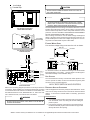
blower section, to allow splicing-in of field-installed wiring, or connect to terminal strip in unit control box.
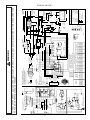
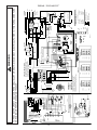
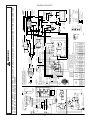
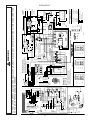
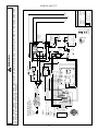
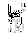
See the unit wiring diagram for electrical connections.
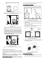
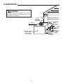
Fork Lift From
Back Of Unit
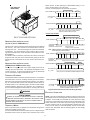
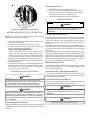
ROOM THERMOSTAT
OUTDOOR UNIT
PH__C02E
C/X
G
Y
R
O
W1
W2
E
C/X
G
Y
R
O
W
W1
W2
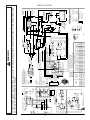
Wiring shown is for D9945804 (THSMEC1H2BA) thermostat.
ROOM THERMOSTAT
C/X
G
Y
R
O
OUTDOOR UNIT
PH__C02E
C/X
G
Y
R
O
W2
E
W1
W2
W
Wiring shown is for 10636701(THSADC1H2BA) or
10636702 (THSMDC1H2BA) thermostat
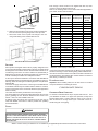
PHD60 TWO-STAGE
Rigging
Yellow No. 20 Wire in Blower Section
DUCT CONNECTIONS
ROOM THERMOSTAT
C
G
Y2
Y1
R
O
W1
W2
Y
R
O
W
W1
W3
HORIZONTAL AIRFLOW INSTALLATIONS
(24, 30, 36, 42
AND
PHB48 MODELS)
OUTDOOR UNIT C/X
G
PHD60C02E
(HEATER KIT CONTROL BOX)
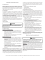
Two three-inch collar connections and two square flanges are shipped
with the unit. The collar connections are located in the return air
opening of the unit. The square flanges are inside the unit blower
compartment. The square flanges can be used for either connecting 16x16 ductwork to the unit or used with a Horizontal Duct Cover
kit (CHK001A).
To install the collar connections, remove the two collars, reverse and
snap them back into place in the outlet and inlet openings. Be sure
the flanges are to the outside of the unit. Secure with screws provided.
W2
Wiring shown is for
1213412 (1F95-371) thermostat.
NOTE: If Electric Heater Kit is not installed or low voltage connection is made
in unit control box, connect as follows.
HORIZONTAL AIRFLOW INSTALLATIONS
ROOM THERMOSTAT
C
G
Y2
Y1
R
O
W1
OUTDOOR UNIT
PHD60C02E
(CONTROL BOX)
C
G
Y
Y1
R
O
W
W2
W3
Wiring shown is for 1213412 (1F95-371) thermostat.
ROOM THERMOSTAT
C/X
G
Y
R
O
W1
W2
E
OUTDOOR UNIT
PH__CC2E
C/X
G
Y
R
O
W
W1
W2
(PHD48/60 and PHB60 models only)
These units are equipped with 14x14 square supply and return air
openings for horizontal air flow. The openings are flanged for ease
of duct connection. A 16x16 Horizontal Duct Cover kit (CHK001A)
can be used with the clips provided with the unit.
Wiring shown is for D9945804 (THSMEC1H2BA) thermostat.
THERMOSTAT PLACEMENT
Thermostat should be mounted 5 feet above the floor, on a vibration
free inside wall in a room or a hallway that has good air circulation.
Movement of air should not be obstructed by furniture, door, draperies, etc. The thermostat should not be mounted where it will be affected by drafts, hot or cold water pipes or air ducts in walls, radiant
heat from fireplace, lamps, the sun, television, etc. Consult the Instruction Sheet packaged with thermostat for mounting instructions.
ROOM THERMOSTAT
C/X
G
Y
R
O
OUTDOOR UNIT
PH__CC2E
C/X
G
Y
R
O
W
W2
E
W1
W2
Wiring shown is for 10636701(THSADC1H2BA) or
10636702 (THSMDC1H2BA) thermostat
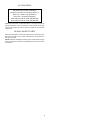
Typical Thermostat and Unit 24 Volt Wiring Hoo2kup
WARNING
ELECTRICAL CONNECTIONS
SHOCK HAZARD!
DISCONNECT ALL ELECTRICAL POWER BEFORE ELECTRICALLY CONNECTING
OR SERVICING THIS UNIT. FAILURE TO DISCONNECT THE ELECTRICAL POWER
NOTE: The units are designed for operation on 60 Hz current and at
the voltages shown on the rating plate. All internal wiring in the unit is
complete. For the PHB**CC and PHD**CC units, the power supply
connection for the heater and unit will be at the circuit breaker in the
heater control box. For all others, the power supply may be brought
into the contactor (refer to unit wiring diagram supplied with unit).
Ensure 24 volt wiring is connected between the unit control panel
and the room thermostat. See the following figures for low voltage
field connection.
BEFORE WORKING ON THIS PRODUCT CAN CREATE A HAZARD LEADING TO
PERSONAL INJURY AND/OR DEATH.
THERMOSTAT WIRING
When an electric heater is installed, the thermostat wiring will be
made at the heater accessory box.
If a unit is installed without electric heaters, the low voltage wiring to
the blower section can be cut, either in the control box area or in the
4