1
Low Voltage
Terminal Strip
CAUTION
TO AVOID PROPERTY DAMAGE OR PERSONAL INJURY DUE TO FIRE, USE
ONLY COPPER CONDUCTORS.
C
G
Y
R
W
CAUTION
ON
W1
ON
W2 O
TO PREVENT IMPROPER AND DANGEROUS OPERATION DUE TO WIRING
ERRORS, LABEL ALL WIRES PRIOR TO DISCONNECTION WHEN SERVICING
CONTROLS.
VERIFY PROPER OPERATION AFTER SERVICING.
The best protection for the wiring is the lowest rated fuse or circuit
breaker which will supply power to the unit during normal operation
without nuisance trips. Such a device will provide maximum circuit
protection. DO NOT EXCEED THE MAXIMUM OVERCURRENT
DEVICE SIZE SHOWN ON UNIT DATA PLATE.
All line voltage connections must be made through weatherproof
fittings. All exterior power supply and ground wiring must be in approved weatherproof conduit. Low voltage wiring from the unit control panel to the thermostat requires coded cable.
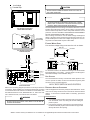
Low Voltage Connection
Heater Kit Control Box
Low Voltage
Terminal Strip
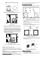
FLEXIBLE WIRING SETUP
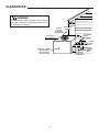
Line and low voltage wiring must enter the unit as shown.
REAR VIEW
ELECTRICAL
Low Voltage Connection
Unit Control Box
T2
RETURN
AIR
SUPPLY
AIR
T1
SIDE VIEW
SIDE VIEW
HEATER
KIT
BLOWER
TO CONTACTOR
GN
BK
ELECTRICAL
LOW
VOLTAGE
THERMOSTAT
BU
G
GY
Y
YL
R
RD
W
BR
W1
BR
RD
BK
5
3
4
1
BR
W2
L1
BK
VT
RD
RD
BK
BK
BU
O
0R
GY
L2
For knockout locations, see dimension drawing in the Product Data
Book applicable to your model* . Use the Single Point wiring kit to
add further flexibility to the installation wiring.
CB2
BK
BK
BU
RD
YL
1
2
3
4
5
6
7
8
9
L2
CB1
L1
SEQUENCER #1
BK
BR
COMPRESSOR
EVAP
COIL
GND-75
C
ELECT.
CONTROL
BOX
RD
VT
OL
FIELD
CONNECTION
208/240 VAC
1ø
USE COPPER
CONDUCTORS
ONLY-75°C MIN
UNIT VOLTAGE
208/230 VAC 1ø
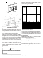
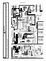
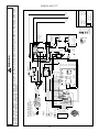
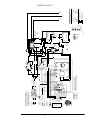
The unit transformer is factory connected for 230V operation. If the
unit is to operate on 208V, reconnect the transformer primary lead
as shown on the unit wiring diagram.
RD
BK
BK
OL
10KW
AIR CIRCULATION AND FILTERS
Field Connection
DOWNSHOT AIRFLOW CONVERSION
Refer to the unit wiring diagram (see back of manual) for electrical
connections. When installed, the unit must be electrically grounded
in accordance with local codes or in the absence of local codes, with
the National Electrical Code, ANSI/NFPA No. 70, and/or the CSA
C22.1 Electrical Code, if an external source is utilized.
Units are shipped from the factory ready for horizontal airflow. These
units can be easily converted from horizontal to downshot airflow
delivery. If conversion to vertical airflow is necessary, proceed as
follows:
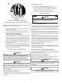
Blower Rotation
WARNING
1. Cut insulation around bottom openings and remove panels
from the bottom of the unit, saving the screws holding the
panels in place.
2. From the rear of the unit, remove the four (4) screws securing
the blower assembly in place and loosen the two (2) screws
directly below the duct opening.
TO AVOID THE RISK OF ELECTRICAL SHOCK, WIRING TO THE UNIT MUST BE
POLARIZED AND GROUNDED.
*NOTE: Please contact your distributor or our website for the applicable product data book referred to in this manual.
5