1
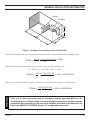
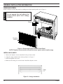
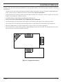
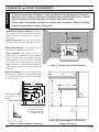
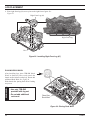
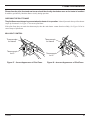
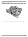
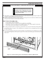
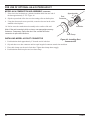
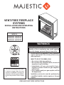
VENT-FREE FIREPLACE
SYSTEMS
INSTALLATION AND OPERATING
INSTRUCTIONS
MODELS:
32VFHNVC, 32VFHPVC
36VFHNVC, 36VFHPVC
42VFHNVC, 42VFHPVC
WARNINGS
WARNINGS
If the information in this manual is not followed
exactly, a fire or explosion may result causing
property damage, personal injury or loss of life.
– Do not store or use gasoline or other flammable
vapors and liquids in the vicinity of this or any
other appliance.
– WHAT TO DO IF YOU SMELL GAS
This is an unvented gas-fired heater.
It uses air (oxygen) from the room
in which it is installed. Provisions for
adequate combustion and ventilation
air must be provided. Refer to page
10.
• Do not try to light any appliance.
• Do not touch any electrical switch; do not use
any phone in your building.
• Immediately call your gas supplier from a
neighbor's phone. Follow the gas supplier's
instructions.
• If you cannot reach your gas supplier, call the
fire department.
– Installation and service must be performed by
a qualified installer, service agency or the gas
supplier.
READ AND SAVE THESE INSTRUCTIONS
CONTENTS
Important Safety Information................................. 3
Product Features...................................................... 5
Operation............................................................... 5
Specifications........................................................... 7
Ignition Controls..................................................... 7
Pilot........................................................................7
Thermal Generator................................................. 7
Getting Started.......................................................... 8
General Installation Information............................. 9
Firebox Dimensions............................................... 9
Codes...................................................................10
Adequate Combustion and Ventilation Air........... 10
Removing Screen................................................ 12
Installing Canopy................................................. 12
Location of Fireplace............................................. 13
Clearances and Height Requirements.................. 14
Fireplace Framing.................................................. 15
Connecting the Gas................................................ 17
Checking Gas Pressure......................................... 18
Milli-Volt Control................................................... 18
Electrical Wiring (Milli-Volt)................................... 19
Connecting Optional Wall Switch......................... 19
Connecting Remote Receiver.............................. 20
Checking System Operation................................ 20
Log Placement........................................................ 21
Flame Appearance.................................................. 25
Checking the Burner Flame . ................................ 26
Operating Instructions........................................... 27
For Your Safety Read Before Lighting................. 27
Milli-Volt Control Lighting Instructions.................. 28
Match Lighting Instructions.................................. 29
Cleaning and Servicing.......................................... 29
Blower and Other Optional Equipment................ 30
Illustrated Parts Breakdown.................................. 31
Logs.....................................................................31
Heater..................................................................32
Cabinet.................................................................34
Troubleshooting..................................................... 36
Trim Installation...................................................... 38
Using Optional Outside Air Kit.............................. 40
Warranty..................................................................43
71D0533
IMPORTANT SAFETY INFORMATION
INSTALLER
Please leave these instructions with the appliance.
OWNER
Please retain these instructions for future reference.
IMPORTANT
WARNING
Read these instructions carefully before installing or trying to operate this vent-free gas heater.
•Any change to this heater or its controls can be dangerous.
•Improper installation or use of the heater can cause serious injury or death from fire,
burns, explosion or carbon monoxide poisoning.
•Do not allow fans to blow directly into the fireplace. Avoid any drafts that alter burner
flame patterns.
•Do not use a blower insert, heat exchanger insert or other accessory, not approved for
use with this heater where applicable.
1. Due to high temperatures, the appliance should be
located out of traffic and away from furniture and
draperies.
2. Children and adults should be alerted to the hazard
of high surface temperature and should stay away to
avoid burns or clothing ignition.
3. Young children should be carefully supervised when
they are in the same room with the appliance.
4. Do not place clothing or other flammable material on
or near the appliance.
5. Any safety screen or guard removed for servicing an
appliance, must be replaced prior to operating the
heater.
6. Installation and repair should be done by a qualified
service person.
7. To prevent malfunction and/or sooting, an unvented
gas heater should be cleaned before use and at least
annually by a professional service person. More
frequent cleaning may be required due to excessive lint from carpeting, bedding materials, etc. It is
imperative that control compartments, burners and
circulating air passageways be kept clean.
8. CARBON MONOXIDE POISONING: Early signs of
carbon monoxide poisoning are similar to the flu with
headaches, dizziness and/or nausea. If you have these
signs, obtain fresh air immediately. Have the heater
serviced as it may not be operating properly.
9. The installation must conform with local codes or, in
the absence of local codes, with the National Fuel Gas
Code, ANSI Z223.l/NFPA54.
71D0533
10. This unit complies with ANSI Z21.11.2 Unvented
Heaters.
11. Do not install the heaters in a bathroom or bedroom.
12. Correct installation of the ceramic fiber logs, proper
location of the heater, and annual cleaning are necessary to avoid potential problems with sooting. Sooting,
resulting from improper installation or operation, can
settle on surfaces outside the fireplace. See log placement
instructions for proper installation.
13. Avoid any drafts that alter burner flame patterns. Do not
allow fans to blow directly into fireplace. Do not place
a blower inside burn area of firebox. Ceiling fans may
create drafts that alter burner flame patterns. Sooting and
improper burning will occur.
14. Caution: Candles, incense, oil lamps, etc. produce
combustion byproducts including soot. Vent-free appliances will not filter or clean soot produced by these types
of products. In addition, the smoke and/or aromatics
(scents) may be reburnt in the vent-free appliance which
can produce odors. It is recommended to minimize the
use of candles, incense, etc. while the vent-free appliance
is in operation.
15. This is an unvented gas-fired heater. It uses air (oxygen)
from the room in which it is installed. Provisions for
adequate combustion and ventilation air must be provided. See page 10.
16. Keep room area clear and free from combustible materials, gasoline and other flammable vapors and liquids.
17. Unvented gas heaters are a supplemental zone heater.
They are not intended to be the primary heating appliance.
Continued on page 4
IMPORTANT SAFETY INFORMATION
Continued from page 3
18. Unvented gas heaters emit moisture into the living area.
In most homes of average construction, this does not pose
a problem. In houses of extremely tight construction,
additional mechanical ventilation is recommended.
19. During manufacturing, fabricating and shipping, various
components of this appliance are treated with certain
oils, films or bonding agents. These chemicals are not
harmful but may produce annoying smoke and smells
as they are burned off during the initial operation of the
appliance; possibly causing headaches or eye or lung
irritation. This is a normal and temporary occurrence.
The initial break-in operation should last two to three
hours with the burner at the highest setting. Provide
maximum ventilation by opening windows or doors to
allow odors to dissipate. Any odors remaining after this
initial break-in period will be slight and will disappear
with continued use.
20. Input ratings are shown in BTU per hour and are for
elevations up to 2,000 feet. For elevations above 2,000
feet, input ratings should be reduced 4 percent for each
1,000 feet above sea level. Refer to the National Fuel
Gas Code.
21. The appliance and its appliance main gas valve must be
disconnected from the gas supply piping system during
any pressure testing of that system at test pressures in
excess of 1/2 psig (3.5 kPa).
This appliance may be
installed in an aftermarket, permanently located,
manufactured (mobile)
home, where not prohibited by local codes.
This appliance is only for
use with the type of gas
indicated on the rating
plate. This appliance is
not convertible for use
with other gases.
22. The appliance must be isolated from gas supply piping
system by closing its equipment shutoff valve during
any pressure testing of the gas supply piping system at
test pressures equal to or less than 1/2 psig (3.5 kPa).
23. Do not use this room heater if any part has been under
water. Immediately call a qualified service technician
to inspect the room heater and to replace any part of the
control system and any gas control which has been under
water.
24. Never burn solid fuels in a fireplace where a unvented
room heater is installed.
25. Always have a fireplace screen in place when the appliance is in operation and, unless other provisions for
combustion air are provided, the screen must have an
opening(s) for induction of combustion air.
71D0533
product features
Screen
On/Off Switch
Piezo
Control
Knobs
Figure 1 - Access to Controls
This vent-free fireplace must be mounted on the floor or on the optional fireplace hearth.
Operation
This unvented gas heater requires no outside venting and burns cleanly with high heating efficiency.
This zero-clearance unvented gas heater can be installed against (or recessed into) any wall that is accessible to a gas line.
71D0533
PRODUCT FEATURES
Natural Gas
Milli-Volt Pressure
Regulator Pressure Setting: 3.5" w.c.
Pilot Regulator: 3.5" w.c.
Gas Inlet Pressure: Max. 10 1/2" w. c.
Min. 5" w.c.
Model Number
32VFHNVC
36VFHNVC
42VFHNVC
Control MILLI-VOLT
MILLI-VOLT
MILLI-VOLT
Gas Rate
Max BTU/Hr
Min BTU/Hr
38,000
38,000
38,000
26,000
26,000
26,000
Propane/LPG
Note: An external regulator is required to reduce supply pressure to a maximum of 13" w.c.
Milli-Volt Pressure
Regulator Pressure Setting: 10" w.c. Gas Inlet Pressure: Max. 13" w.c.
Min. 11" w.c.
Model Number
32VFHPVC
36VFHPVC
42VFHPVC
Control MILLI-VOLT
MILLI-VOLT
MILLI-VOLT
Gas Rate
Max BTU/Hr
Min BTU/Hr
34,000
34,000
34,000
26,000
26,000
26,000
71D0533
specifications
ignition controls
Piezo ignitor allows ignition of the pilot without the use of matches or batteries.
illi-Volt control has four (4) positions:
M
OFF
- All gas to the gas logs is shut off at the valve.
IGN
- Valve position to light/maintain a standing pilot.
ON
- Valve position to turn ON/OFF log set with remote switch/thermostat.
LOW/HI - Variable position to control flame height (heat output). Both front and rear burners are in operation to
provide realistic glow and yellow flame.
Pilot
The gas log heater is fitted with a specially designed safety pilot light (ODS assembly) which senses the amount of oxygen
available in the room and shuts the gas log heater off if the oxygen level begins to drop below a satisfactory level. The pilot
can only be relit when adequate fresh air is available.
Thermal Generator
The milli-volt gas log pilot is fitted with a milli-volt generator to provide power for remote activation.
71D0533
getting started
Make sure you have received all parts:
Check your packing list to verify that all listed parts have been received. You should have the following:
• Unvented gas log grate/burner assembly
• Installation/operating instructions
• Ceramic fiber logs
• Rock wool
• Plastic bag containing crushed volcanic rock
• Trim kit
• Canopy and five (5) mounting screws
WARNING
The milli-volt controlled version of this heater is the only style designed to be operated with optional devices for ON/OFF
functions. The following options may be used with the milli-volt controlled heater. These options are not packaged with the
log set.
• Hand held remote with receiver
• Wall switch with 15' wire
• Wall thermostat with 15' wire
• Hand held thermostat remote with receiver
•Gloves are recommended when handling ceramic fiber logs to prevent skin irritation
from loose fibers. Logs are fragile — handle with care.
Carefully inspect the contents for shipping damage. If any parts are missing or damaged, immediately inform the dealer
from whom you purchased the appliance. Do not attempt to install any part of the appliance unless you have all parts
in good condition.
What you will need for installation:
You must have the following items available before proceeding with installation:
• External regulator (for propane/LPG and 1/2 lb. natural gas systems only)
• Piping which complies with local codes
• Pipe wrench or appropriate size crescent wrench set • Pipe sealant approved for use with propane/LPG (Resistant to sulfur compounds)
• Sediment trap
• Manual shutoff valve
• Tee joint.
• Phillips head screwdriver
71D0533
GENERAL INSTALLATION INFORMATION
In planning the installation for the fireplace it is necessary to determine where the unit is to be installed and whether optional
accessories are desired. Gas supply piping should also be planned. The following steps represent the normal sequence of
installation. Each installation is unique, however, and might require a different sequence.
1. Position fireplace in desired location. Refer to the “Location of Fireplace” and “Clearances and Height Requirements,” and “Firebox Framing” sections found in this
manual. Note: Be sure all packing material has
been removed from underside of the unit.
2. Install canopy and logs per instructions found in this
manual. The canopy MUST be installed for safe operation of the unit.
3. Field wire main power supply to units with fan kit.
Refer to the “Electrical Section” found in this manual.
(Electrical connections should only be performed by an
experienced, licensed certified tradesman).
4. Install optional ON/OFF kit on units with milli-volt
control. Refer to installation instructions included with
the kit and also refer to the “Electrical Wiring” section
found in this manual.
5. Plumb gas line. Refer to the “Connecting the Gas” section found in this manual. (Gas connections should only
be performed by an experienced, licensed / certified
tradesman).
6. Complete finish wall material and/or surround.
D
F
E
32VFHNVC
32VFHPVC
36VFHNVC
36VFHPVC
42VFHNVC
42VFHPVC
A
B
C
D
E
F
G
H
I
J
K
L
37"
32"
16"
29"
18⅝"
23⅜"
13¼"
18"
29⅞"
7⅛"
8"
2¾"
41"
36"
18"
32"
20⅝"
27⅜"
15¾"
17⅝"
34"
9¾"
8¼"
2¼"
47"
42"
18"
38"
20⅝"
33⅜"
15¾"
17⅝"
40"
9¾"
8¼"
2¼"
Figure 2 - Firebox Dimensions with Screen and Log Sets Removed
C
111/4"
¼"
7/16"
5
5 7/16"
I
21
¾"
21 3/4"
B
34 1/2"
34
½"
H
J
2 ½"
2 1/2"
K
6"
6"
5/16"
11 5/16"
71D0533
L
A
G
GENERAL INSTALLATION INFORMATION
CODES
Adhere to all local codes or, in their absence, the latest edition of THE NATIONAL FUEL GAS CODE ANSI Z223.1 or
NFPA54 which can be obtained from:
WARNING
American National Standards Institute, Inc.
1430 Broadway
New York, NY 10018
or
National Fire Protection Association, Inc.
Batterymarch Park
Quincy, MA 02269
Do not install the heater:
•Where curtains, furniture, clothing, or other flammable objects are less than 42" from
the front of the heater.
•In high traffic areas.
•In windy or drafty areas.
ADEQUATE COMBUSTION AND VENTILATION AIR
This heater shall not be installed in a confined space or unusually tight construction unless provisions are provided for
adequate combustion and ventilation air.
The National Fuel Gas Code, (ANSI Z223.1/NFPA54), defines a confined space as a space whose volume is less than 50
cubic feet per 1,000 BTU per hour (4.8 m3 per kw) of the aggregate input rating of all appliances installed in that space, and
an unconfined space as a space whose volume is not less than 50 cubic feet per 1,000 BTU per hour (4.8 m3 per kw) of the
aggregate input rating of all appliances installed in that space. Rooms communicating directly with the space in which the
appliances are installed, through openings not furnished with doors, are considered a part of the unconfined space.
Unusually tight construction is defined as construction where:
a) walls and ceilings exposed to the outside atmosphere have a continuous water vapor retarder with a rating of 1 perm
(6 x 10¹¹ kg per pa/sec-m2) or less with openings gasketed or sealed;
b) weather striping has been added on openable windows and doors, and
c) caulking or sealants are applied to areas such as joints around window and door frames, between sole plates and floors,
between wall-ceiling joints, between wall panels, at penetrations for plumbing, electrical, and gas lines, and at other
openings.
10
71D0533
GENERAL INSTALLATION INFORMATION
Counter
Fireplace
H
W
Figure 3 - Example of a Large Room with 1/2 Wall Divider
The following formula can be used to determine the maximum heater rating per the definition of unconfined space:
BTU/Hr = (L1 + L2) Ft x (W) Ft x (H) Ft x 1000
50
Consider two connecting rooms with an open area between, with the following dimensions:
L1 = 151/2 Ft., L2 = 12 Ft., W = 12 Ft., H = 8 Ft.
1
BTU/Hr = (15 /2 + 12) x (12) x (8) x 1000 = 52800 BTU/Hr
50
If there were a door between the two rooms the calculation would be based only on the room with the heater.
WARNING
WARNING
1
BTU/Hr = (15 /2) x (12) x (8) x 1000 = 29760 BTU/Hr
50
If the area in which the heater may be operated is smaller than that defined as an
unconfined space or if the building is of unusually tight construction, provide adequate
combustion and ventilation air by one of the methods described in the National Fuel
Gas Code, ANSI Z223.1/NFPA54, Section 5.3 or applicable local codes.
71D0533
11
GENERAL INSTALLATION INFORMATION
REMOVING SCREEN
WARNING
Remove fireplace screen frame panel by pushing screen frame panel up and out. See Figure 4.
Do not operate the unit without the
screen frame panel and canopy
installed.
Canopy
Fireplace
Screen
Figure 4 - Removing Fireplace Screen Frame Panel
NOTE: Fireplace screen must be removed to access log box and to install canopy.
INSTALLING CANOPY
1. Remove the fireplace screen as described in the previous section.
2. Align the canopy with the holes in the top frame. See Figure 5.
3. Install and tighten side screws.
4. Make sure the canopy is level and secure. Install the fireplace screen.
Figure 5 - Canopy Installation
12
71D0533
LOCATION OF FIREPLACE
Carefully select the best location for installation of your unvented fireplace. The following factors should be taken into
consideration.
• Clearance to side wall, ceiling, woodwork and window or other combustibles. Refer to “Clearances and Height Requirements” section on page 14. Minimum clearances to combustibles must be maintained.
• Location must not be affected by drafts caused by kitchen exhaust fans, ceiling fans, return air registers for forced air
furnaces / air conditioners, windows or doors.
• Installation must provide adequate ventilation and combustion air.
• DO NOT INSTALL THIS MODEL IN A BEDROOM OR BATHROOM.
• Location should be out of high traffic areas and away from furniture and draperies due to heat from firebox.
• Never obstruct the front opening of the unvented fireplace or restrict the flow of combustion and ventilation air.
• Minimize modifications to existing construction. See Figure 6 below for location suggestions.
• Do not install in the vicinity where gasoline or other flammable liquids may be stored. The unvented firebox must be
kept clear and free from the combustible materials.
Figure 6 - Suggested Locations
71D0533
13
WARNING
CLEARANCES and HEIGHT REQUIREMENTS
The dimensions shown in Figures 7 and 8 and defined in the fireplace manufacturer's
instructions are minimum clearances to maintain when installing this heater. Left and
right clearances are determined when facing the front of the heater.
Follow these instructions carefully to ensure safe installation. Failure to follow
instructions exactly can create a fire hazard.
Sidewall and ceiling clearances: The clearance from the inside of the appliance to any combustible adjacent wall should no be less than 9".
See Figure 7.
Ceiling clearance: The ceiling must be at least
42" from the top of the firebox opening. See Figure
7.
Back wall clearance: The appliance may be
placed against a combustible back wall.
Floor clearance: The fireplace may not be
installed onto any combustible flooring material,
such as carpeting, vinyl or tile without the hearth
or a minimum 22 GA (0.030") metal or a minimum
1/2" wooden base covering the entire width and
depth of the base. Combustible material must be
installed at least one inch away from the front face
of the unit.
Figure 7 - Sidewall and Ceiling Clearances
Mantel clearances: The canopy supplied with
the unit must be installed. If a combustible mantel
is installed. It must meet the clearance requirements
shown in Figure 8.
12"
10"
8"
Combustible material
can contact top of
fireplace.
6"
21/2"
12"
16"
19"
21"
23"
Non-combustible
material only if needed to
cover optional radiant top
panel above canopy.
Figure 8A - Minimum Mantel Clearances
14
Figure 8B - Mantel Heights For Wide Brass
Canopy. See Pg. 35
71D0533
FIREPLACE framing
If unit is to be “built in,” fireplace framing can be built before or after the appliance is set in place. BE SURE THAT ALL
PACKING MATERIAL HAS BEEN REMOVED FROM THE UNDERSIDE OF THE UNIT PRIOR TO SETTING
THE FIREBOX IN PLACE. Construct fireplace framing following Figures 9 through 12. Refer to Figure 2 on page 9 for
fireplace dimensions. The framing headers may rest directly on top of the firebox.
The fireplace may be installed directly on a combustible floor or a raised platform of an appropriate height. Do not place
fireplace on carpeting, vinyl, tile or other soft floor coverings. It may, however, be placed on flat wood, plywood, particle
board or other hard surfaces. Be sure fireplace rests on a solid continuous floor or platform with appropriate framing for
support and so that no cold air can enter from under the firebox.
Anchor fireplace to the side framing members using optional nailing flange kit. See installation instructions included with
the kit.
D
H
F
G
C
A
E
WARNING
Figure 9 - Corner Installation
Unfinished/rough
framing surface
A
B
C
D
E
F
G
H
32VFHNVC
32VFHPVC
37¼"
35"
29"
14⅞"
61¾"
30⅞"
15½"
43¾"
36VFHNVC
36VFHPVC
42VFHNVC
42VFHPVC
41¼"
35"
32"
16⅜"
68⅞"
34½"
17½"
48¾"
47¼"
35"
38"
19⅜"
74⅞"
37½"
17½"
53"
C
Optional bottom radiant panel kits
cannot be covered. Optional top
radiant panels can be covered as
shown in Figure 8.
Unfinished/rough
framing surface
G
A
/2" or 5/8"
1
Figure 10- Inside Chase Installation
C
or
equivalent
clearance
for drywall/
finishing
G
B
A
A
Figure 11 - Stud Location
71D0533
Unfinished/rough Figure 12- Recessed Installation
framing surface
5/8"
or equivalent
clearance for
drywall/finishing
materials
15
FIREPLACE framing
When finishing a custom cabinet, mantel, or other built-in enclosure,
the opening size to accommodate the fireplace with trim installed is
as follows:
32VFHNVC
32VFHPVC
36VFHNVC
36VFHPVC
42VFHNVC
42VFHPVC
K
J
37⅞"
35⅞"
41⅞"
35⅞"
47⅞"
35⅞"
WARNING
WARNING
Figure 13 - Custom Cabinet
The fireplace must be installed giving
full consideration to the clearance and
height requirements identified in this
manual.
1. Bend out the nailing flanges located on each side of the firebox.
2. Slide the firebox into prepared framing or position firebox in its final position and frame later.
3. Level the firebox by checking the top edge of the firebox. Shim if necessary.
4. Anchor firebox to the side framing members using 8d nails or other suitable fasteners. Refer to Figure 14.
5. The canopy must be installed for safe operation of the heater. Refer to page 12 for canopy installation details.
Nail Sides
Through Nailing
Flanges
Figure 14 - Location of Nailing Flanges
16
71D0533
CONNECTING THE GAS
CAUTION
NOTICE: A qualified gas appliance installer must connect the heater to the gas supply. Consult all local codes.
Use new black iron or steel pipe. Internally tinned copper or copper tubing can be used
per National Fuel Code, section 2.6.3, providing gas meets hydrogen sulfide limits, and
where permitted by local codes. Gas piping system must be sized to provide minimum
inlet pressure (Listed on Data Plate) at the maximum flow rate (BTU/Hr). Undue pressure
loss will occur if the pipe is too small.
A manual shutoff valve must be installed upstream of the appliance. Union tee and
plugged 1/8" NPT pressure tapping point should be installed upstream of the appliance.
See Figure 15.
Pipe Coupling
To Heater
Valve
Pipe
Locations that the Pressure
Tapping Point May Be Installed
Stainless
Flexible Tube
Manual Shutoff
Valve
Gas Supply
Inlet
Figure 15 - Gas Connection
WARNING
IMPORTANT: Hold heater valve firmly with a wrench to prevent movement when connecting to inlet pipe.
Check gas type: The gas supply must be the same as stated on the heater’s rating
plate. If the gas supply is different, DO NOT INSTALL THE HEATER. Contact your dealer
for the correct model.
Always use an external regulator for all propane/LPG heaters and high pressure one to two-pound systems only, to
reduce the supply tank pressure to a maximum of 13" w.c. This is in addition to the internal regulator in the heater valve.
71D0533
17
WARNING
WARNING
CHECKING GAS PRESSURE
Connecting directly to an
unregulated propane/LPG tank
can cause an explosion.
When tightening up the joint to the valve, hold the valve securely to prevent movement.
Test all gas joints from the gas meter to the heater valve for leaks using a gas analyzer or soap and water solution after completing connection. DO NOT USE AN OPEN FLAME.
Check the gas pressure with the appliance burning and the control set to HIGH.
Milli-volt Control (Figure 16)
Test Port “OUT”
The valve regulator controls the burner pressure which
should be checked at the pressure test point.
Turn captured screw counter clockwise two or three
turns and then place tubing to pressure gauge over test
point (Use test point “OUT” closest to control knob).
After taking pressure reading, be sure and turn captured
screw clockwise firmly to re-seal. Do not over torque.
Check for gas leaks.
Figure 16 - Pressure Test Point Location
Milli-Volt Control
18
71D0533
ELECTRICAL WIRING
WARNING
The milli-volt valve is a self-powered combination gas control that does not require 110 Vac to operate.
Label all wires prior to disconnection
when servicing controls. Wiring
errors can cause improper and
dangerous operation. Verify proper
operation after servicing.
ODS
Pilot
On/Off
Switch
ODS
Pilot
Wall
Switch
Valve
On/Off
Switch
Spade
Terminal
TH = 3
TP = 1
TP/TH = 2
Switch
Figure 17 - Wiring Diagram
Connecting Optional Wall Switch
Optional Wall
Switch or Remote
Receiver
1. Use 18 awg, two-wire cable, 15 feet maximum length.
2. At one end of the cable, connect both wires to the wall switch or thermostat. At the other end, connect one wire to
TP/TH and one wire to TH, or connect the wall switch/thermostat to the two male (0.25") terminals on the left side of
the unit. The color of the wires does not matter.
71D0533
19
ELECTRICAL WIRING
Connecting Remote Receiver
THESE INSTRUCTIONS SUPERCEDE THE SECTION ENTITLED “HEARTH MOUNT” IN THE MILLIVOLT HAND-HELD REMOTE INSTRUCTIONS SUPPLIED WITH THE REMOTE.
1. Remove cover on control panel to show opening for
remote receiver. See Figure 18.
2. Connect the remote connectors located in the unit (Figure
18).
Remote
Receiver
3. Slide remote receiver in the opening of control panel.
Use two screws provided to attach remote receiver to the
control panel. See Figure 18.
4. Replace cover.
Cover
NOTE:Do not place remote in combustion
chamber.
Checking System Operation
The milli-volt system and individual components may be checked with a milli-volt
meter having a 0-1000 mV range. Conduct
each check shown in chart below by connection meter test leads to terminals as
indicated.
Figure 18 - Installing Remote Receiver
CHECK
TO
TEST
TEST
CONNECT
METER
SWITCH OR
METER
LEADS TO
THERMOSTAT
READING
TERMINALS
CONTACTS
SHOULD BE
A
COMPLETE
SYSTEM
2 & 3
CLOSED
CLOSED
B
THERMOPILE
OUTPUT
1 & 2
OPEN
OPEN
A. Complete Milli-Volt System Check
(“A” Reading - Thermostat contacts CLOSED - Control Knob “ON” - Main burner should turn ON)
a. If the reading is more than 100 milli-volts and the automatic valve still does not come on, replace the control.
b. If the closed circuit reading (“A” reading) is less than 100 millivolts, determine cause for low reading, proceed to
Section B below.
B. Thermopile Output Reading Check
(“B” Reading - Thermostat contacts OPEN - Main burner OFF)
20
1. Check gas pressure to the unit. If gas pressure is within minimum and maximum on data plate, then check pilot
voltage, 325 millivolts minimum. If the minimum milli-volt reading is not obtainable, replace pilot.
71D0533
LOG PLACEMENT
WARNING
Before you begin — This unit is supplied with six (6) ceramic fiber logs. Do not handle these logs with your bare hands.
Always wear gloves to prevent skin irritation from ceramic fibers. After handling the logs, wash your hands gently with
soap and water to remove any traces of fibers.
The positioning of the logs is critical to the safe and clean operation of this heater. Sooting and
other problems may result if the logs are not properly and firmly positioned in the appliance. Never
add additional logs or embellishments such as pine cones, vermiculite or rock wool to the heater.
Only use the logs and TPB-RW (rock wool) supplied with the unit.
Failure to position the parts in accordance with diagrams below or to use only parts specifically
approved for this heater may result in property damage or personal injury.
Right Base
Log (#1)
Installing Blazing Oak logs on
Burner
1. Place right base log (#1)
on two pins located on the
right side of the grate. See
Figure 19.
Pins
Figure 19 - Installing
Right Base Log (#1)
Rear Log (#2)
2. Place rear log (#2) on
two pins on back of
grate allowing the right
end of the rear log to rest
on top of the right top Pins
log.
See Figure 20.
Figure 20 - Installing
Rear Log (#2)
Right Base Log (#1)
71D0533
21
LOG PLACEMENT
3. Place left base log (#3) on two pins on left side of grate.
See Figure 21.
Left Base Log
(#3)
Pins
Figure 21 - Installing Left Base Log (#3)
Right top log (#4)
4. Place right top log (#4) on two pins located to the
left of right base log. See Figure 22.
Right Top Log
(#4)
Right Bottom
Log (#1)
Pins
Figure 22 - Installing Right Top Log (#4)
22
71D0533
LOG PLACEMENT
5. Place right end of left top log (#5) on bottom center grate pin. Place middle of left top log (#5) on pin just to the right
of the left base log. Rest the left end of left top log (#5) on the left base log. See Figure 23.
Left Top Log
(#5)
Pin
Left Base
Log (#3)
Bottom Center Pin
Figure 23 - Installing Left Top Log (#5)
71D0533
23
log placement
6. Place right front log (#6) on two pins on the right front of grate. See
Figure 25.
Right Front Log (#6)
Right Front Log
Pins
Figure 25 - Installing Right Front Log (#7)
Placing Rock Wool
After installing logs, place TPB-RW (Rock
Wool) in dime-size pieces evenly across the
burner surface in between the logs. Do not add
additional Rock Wool. See Figure 26
warning
Wash hands after placing Rock Wool. Itching
may occur.
.
• Use only TPB-RW
provided with log set.
• Do not add additional
rock wool.
Dime-Size
Rock Wool
Figure 26 - Placing Rock Wool
24
71D0533
FLAME APPEARANCE
Flames from the pilot, front and rear burner should be visually checked as soon as the heater is installed.
In addition, periodically check the flames visually during operation.
Checking the pilot flame
The pilot flame must always be present when the heater is in operation. It should just touch the top of the thermo-
couple tip for natural. See Figure 27 for correct pilot flame.
If the pilot flame does not touch the thermocouple, then the main burner cannot function reliably. See Figure 28 for in-
correct shape of pilot flame.
Milli-volt Control
Thermocouple
for Natural
Thermocouple
for LP
Figure 27 - Correct Appearance of Pilot Flame
71D0533
Thermocouple
for Natural
Thermocouple
for LP
Figure 28 - Incorrect Appearance of Pilot Flame
25
CHECKING THE BURNER FLAME
In normal operation at full rate after 15 minutes, the following flame appearances should be observed:
Figure 29 - Correct Appearance of Rear Flames of Blazing Oak
Burner will have a random pattern of yellow flames as shown in Figure 29. There should be glowing embers on the front
burner. Note: The front flames and embers will be an opaque orange color during the burn off time.
26
71D0533
OPERATING INSTRUCTIONS
WARNING
for your safety read before lighting
If you do not follow these instructions
exactly, a fire or explosion may result
causing property damage, personal
injury or loss of life.
A. This appliance is equipped with a piezo ignition device which automatically lights the pilot. If pilot is not
working see Match Lighting Instructions on page 29.
B. BEFORE OPERATING smell all around the appliance area for gas. Be sure to smell next to the floor because
some gas is heavier than air and will settle on the floor.
WHAT TO DO IF YOU SMELL GAS:
• Do not attempt to light any appliance.
• Do not touch any electric switch; do not use any phone in your building.
• Immediately call your gas supplier from a neighbor's phone. Follow the gas supplier's instructions.
• If you cannot reach your gas supplier, call the fire department.
C. Use only your hand to push in, or turn the gas control knob. Never use tools. If the knob will not push in or
turn by hand, don't try to repair it. Call a qualified service technician. Force or attempted repair may result
in a fire or explosion.
D. Do not use this appliance if any part of it has been under water. Immediately call a qualified service technician to inspect the appliance and to replace any part of the control system and any gas control that has been
under water.
On/Off Switch
Piezo
Ignitor
Control Knobs
Figure 30 - Location of Piezo Ignitor, Control Knobs and Switch on Milli-Volt Unit
71D0533
27
OPERATING INSTRUCTIONS
MILLI-VOLT CONTROL
LIGHTING INSTRUCTIONS
1. STOP! Read the safety information label.
2. Make sure the manual shutoff valve is fully open.
3. This gas log set is equipped with an ignition device (piezo) which automatically lights the pilot. If piezo
ignitor does not light the pilot, refer to instructions for “Match Lighting Instructions,” page 29.
4. Turn gas control knob clockwise
to the OFF position, and turn ON/OFF switch to OFF position.
5. Wait (5) minutes to clear out any gas. Then smell for gas, including near the floor. If you smell gas, STOP!
Follow “What to Do if You Smell Gas,” page 27. If you don't smell gas, go to next step.
6. From OFF position, turn the gas control knob counterclockwise
to IGN position. Push in
control knob for 5 seconds. NOTE: If you are running the heater for the first time, it will be
necessary to press in the control knob for 30 seconds to allow air to bleed out of the gas
piping.
7. With the control knob pushed in, push in and release the piezo ignitor button to light the pilot.
8. Continue pushing the control knob in for a further 60 seconds to prevent the flame detector from shutting
off the gas while the probe is warming up. Release the control knob.
9. Turn gas control knob counterclockwise
to the ON position.
10. After the pilot has been lit for one minute, the burners can be turned on. Turn the ON/OFF switch to ON
position or adjust thermostat to desired setting.
11. If the gas logs will not operate, follow the instructions “To Turn Off Gas To Heater” below and call your
service technician or gas supplier.
On/Off Switch
Hi/Lo Control
Ignitor Pilot Control
Piezo
Figure 31 - Pilot
Figure 32 - Control Cover Plate for Milli-Volt
TO TURN OFF GAS TO HEATER
1. Turn control knob clockwise
to OFF position to completely shut off the heater.
2. If applicable: Turn ON/OFF switch to OFF position and/or set thermostat (if present) to lowest setting.
3. If applicable: Turn off all electric power to the heater.
28
71D0533
OPERATING INSTRUCTIONS and Cleaning and Servicing
match lightinG instructions
1. Remove any items necessary for easy access to the pilot (for example: logs, screens, etc.).
2. Follow appropriate lighting instructions found previously. Instead of pushing and releasing the piezo
button, light a match and hold the flame to the end of the pilot and ignite the pilot.
3. After control knob has been released and pilot stays lit, reinstall any items that were removed for pilot
access.
4. Call a qualified service technician for repair or replacement of the piezo ignitor.
CLEANING AND SERVICING
WARNING
Annual inspection and cleaning by your dealer or qualified service technician is recommended to prevent
malfunction and/or sooting.
Turn off heater and allow to cool before
cleaning. Disconnect electrical power
before cleaning or servicing.
Remove logs, handling carefully by holding gently at each end. Gloves are recommended to prevent skin irritation from
ceramic fibers. If skin becomes irritated, wash gently with soap and water. Refer to manual for correct log placement.
Periodic Cleaning - Refer to parts diagram for location of items discussed below.
• Do not use cleaning fluid to clean logs or any part of heater.
• Brush logs with soft bristle brush or vacuum with brush attachment.
• Vacuum loose particles and dust from the front and rear burner, control and piezo covers and grate weldment.
• Inspect and clean burner air intake holes. Remove lint or particles with vacuum, brush, or pipe cleaners. Failure to keep
air intake holes clean will result in sooting and poor combustion.
• External case should be dusted and wiped with a wet soapy cloth.
Annual Cleaning/Inspection - Refer to parts diagram for location of items discussed below.
• Inspect and clean burner air intake holes. Remove lint or particles with vacuum, brush or pipe cleaners. Failure to keep
air intake holes clean will result in sooting and poor combustion.
• Inspect and clean all burner ports.
• Inspect ODS pilot for operation and accumulation of lint at air intake holes.
• Verify flame pattern and log placement for proper operation.
• Verify smooth and responsive ignition of main burner and rear burner.
71D0533
29
BLOWER AND OTHER OPTIONAL EQUIPMENT
OPTIONAL EQUIPMENT
Forced Air Kit
If you are installing the forced air kit, Model BLOTMC, see the installation instructions provided with the kit for
electrical wiring requirements, or the blower installation section. The firebox must be connected to main power
supply at time of firebox installation. The blower must be installed prior to the installation of the unvented heater.
The electrical connections must be made before the firebox is framed and enclosed in the finished walls.
optional Trim
Optional brass or pewter trim kits can be used in place of the factory supplied black trim.
optional brick
30
Electrical connections should only be performed by a qualified, licensed electrician,
main power must be off when connecting to main electrical power supply or performing
service.
CAUTION
WARNING
Optional Tavern Brown and Cottage Red firebrick kits can be installed. Refer to installation instructions provided
with kit.
71D0533
illustrated parts breakdown
REPLACEMENT PARTS ARE AVAILABLE THROUGH YOUR RETAILER.
BLAZING OAK LOGS
Item
1
2
3
4
5
6
Description
Right Base Log
Rear Log
Left Base Log
Right Top Log
Left Top Log
Right Front Log
Qty
BOCL18
BOCL24
BOCL30
1
1
1
1
1
1
70D0131
70D0132
70D0133
70D0134
70D0140
70D0137
70D0041
70D0042
70D0043
70D0044
70D0066
70D0047
70D0231
70D0232
70D0233
70D0234
70D0239
70D0237
#6
#4
#5
#2
#3
WARNING
#1
71D0533
Failure to position the parts in
accordance with these diagrams or
failure to use only parts specifically
approved with this appliance may
result in property damage or personal
injury.
31
WARNING
illustrated parts breakdown
Failure to position the parts in accordance with these diagrams or failure to use only
parts specifically approved with this heater may result in property damage or personal
injury.
6
5
3
9
4
8
7
2
1
32
10
11
71D0533
REPLACEMENT PARTS list
REPLACEMENT PARTS ARE AVAILABLE THROUGH YOUR RETAILER.
Burner assembly
TPB24
Item
Qty
Natural
Propane
14D0503
14D0503
1
Piezo Ignitor
1
2
Piezo Wire
1
00K0632
00K0632
3
Burner
1
70D0010
70D0010
4
Control Valve
1
14D0467
14D0468
5
Injector
1
70D0064
57D0680
6
ODS Pilot Assembly
1
14D0473
14D0477
7
On/Off Switch
1
32D0232
32D0232
8
Pilot Regulator
1
14D0469
—
Hi/Lo Knob
Pilot On/Off Knob
Control panel
1
1
1
37D0011
37D0010
54D0233
37D0011
37D0010
54D0233
9
10
11
Accessories sold separately
Description
Wall Thermostat Kit
WT
Remote (On/Off)
RCB, RCM, WMTD
Thermostat Remote
RCST, RCT, WWTD
Remote Receiver Cover Ember
RRCE
Remote Receiver Cover Metal
RRCM
Remote Touch Light (On/Off)
TLM
Remote Touch Light T-stat
TLT
Cast Iron Grate and Andirons
Rock Wool Bag
71D0533
Part Number
CIGA
Do not fit 32VFH
TPB24-RW
33
illustrated parts breakdown
3
54
4
7
1
56
2
8
6
3
4
76
WARNING
9
34
Failure to position the parts in accordance with these
diagrams or failure to use only parts specifically
approved with this appliance may result in property
damage or personal injury.
71D0533
REPLACEMENT PARTS list
REPLACEMENT PARTS ARE AVAILABLE THROUGH YOUR RETAILER.
Item
Description
32VFHC
36VFHC
42VFHC
1
1
1
71d0023
71D0075
BLMTK32C
71D0500
71D0545
BLMTK36C
71D1000
71D1026
BLMTK42C
1
1
8
1
L32BRM
L32PWM
26D0695
BLOTMC
L36BRM
L36PWM
26D0697
BLOTMC
1
1
1
1
1
1
1
1
BRTK32C
PWTK32C
BLTK32C
BRMTK32C
PWMTK32C
FB32CR
AK-4
BRC32
BRTK36C
PWTK36C
BLTK36C
BRMTK36C
PWMTK36C
FB36CR
AK-4
BRC36
Qty
Standard Features
1
2
4
3
3
3
7
Canopy
Screen Assembly Black Trim Kit
Feature Options
Brass Louver Kit
Pewter Louver Kit
Black Louver Blower with Rheostat
L42BRM
L42PWM
26D0699
BLOTMC
Accessories
71D0533
4
4
4
4
4
5
6
1
Curved Design Brass Trim Curved Design Pewter Trim Curved Design Black Trim
Brass Trim Kit
Pewter Trim Kit
Cottage Red Firebrick Outside Air Kit
Wide Brass Canopy
BRTK42C
PWTK42C
BLTK42C
BRMTK42C
PWMTK42C
FB42CR
AK-4
BRC42
35
WARNING
WARNING
TROUBLESHOOTING
Turn appliance OFF and allow to cool
before servicing. Only a qualified
service person should service and
repair the heater.
Note: All troubleshooting items are listed in order of operation.
OBSERVED PROBLEM
POSSIBLE CAUSE
REMEDY
When ignitor button is pressed,
there is no spark at ODS/pilot.
1. Ignitor electrode positioned wrong.
2. Ignitor electrode is broken.
3. Ignitor electrode not connected to ignitor
cable.
4. Ignitor cable pinched or wet. Keep ignitor cable
dry.
5. Broken ignitor cable.
6. Bad piezo ignitor.
1
2.
3.
4.
Appliance produces unwanted
odors.
1. Appliance burning vapors from paint, hair
spray, glues, etc.
2. Gas leak.
3. Initial burn off.
1. Ventilate room. Stop using odor causing
products while heater is running.
2. Locate and correct all leaks.
3. Ventilate room and turn unit on high until
odor is gone. Odor should be gone after
6 hours of continuous use.
Appliance shuts off during use.
1. Not enough fresh air is available for ODS/ pilot
to operate.
2. Low line pressure.
3. ODS/pilot is partially clogged.
4. Defective Thermopile.
1. Open window and/or door for ventilation.
2. Contact local gas company.
3. Clean ODS/pilot.
4. Check pilot flame, check wire connections, check output, should be 325 millivolts across TH/TP and TP Terminals
with ON/OFF switches off.
5. Check for bottom riser on glass door,
sunken fireplace, excessive lava rock/cinders densely packed against grate.
5. Restrictions in incoming air flow.
Replace ignitor.
Replace ignitor.
Reconnect ignitor cable.
Free ignitor cable if pinched by any
metal or tubing.
5. Replace ignitor cable.
6. Replace piezo ignitor.
Gas odor even when control knob
is in OFF position.
1. Gas leak.
2. Control valve defective.
1. Locate and correct all leaks.
2. Replace control valve.
When ignitor button is pressed,
there is spark at ODS pilot, but
no ignition.
1. Gas supply turned off or manual shutoff valve
closed.
2. Control knob not in PILOT position.
3. Control knob not pressed in while in PILOT
position.
4. Air in gas lines when installed.
1. Turn on gas supply or open manual
shutoff valve.
2. Turn control knob to PILOT position.
3. Press in control knob while in PILOT
position.
4. Continue holding down control knob.
Repeat igniting operation until air is
removed.
5. Replace ODS/pilot assembly or get it
serviced.
6. Replace gas regulator.
5. ODS/pilot is clogged.
6. Gas regulator setting is not correct.
36
71D0533
WARNING
TROUBLESHOOTING
If the gas quality is bad, your pilot may not stay lit, the burners may produce soot and
the heater may backfire when lit. If the gas quality or pressure is low, contact your local
gas supplier immediately.
OBSERVED PROBLEM
POSSIBLE CAUSE
REMEDY
ODS/pilot lights, but flame
goes out when control knob is
released.
1. Control knob not fully pressed in.
2. Control knob not pressed in long enough.
1. Press in control knob fully.
2. After ODS/pilot lights, keep control
knob pressed in for 30 seconds.
3. Fully open manual shutoff valve.
4. Hand tighten thermocouple connection
until snug, then tighten 1/4 turn more.
5a.Contact local gas company.
5b.Clean pilot with vacuum cleaner.
3. Manual shutoff valve not fully open.
4. Thermocouple connection loose at control
valve.
5. Pilot flame not touching thermocouple, which
allows thermocouple to cool, causing pilot
flame to go out. This problem could be caused
by either low gas pressure, or a dirty or partially
clogged ODS/pilot.
6. Thermocouple damaged.
7. Control valve damaged.
6. Replace thermocouple.
7. Replace control valve.
Burner does not light after ODS/
pilot is lit.
1. Burner orifice is clogged.
2. Burner orifice diameter is too small.
3. Inlet gas pressure is too low.
1. Clean orifice.
2. Replace burner orifice.
3. Contact qualified service person.
Burner backfires during combustion.
1. Manifold pressure is too low.
2. Burner orifice is clogged.
1. Contact local gas company.
2. Clean burner or replace burner orifice.
Slight smoke or odor during
initial operation.
1. Burner orifice is clogged or damaged.
2. Burner is damaged.
3. Gas regulator defective.
1. Clean burner or replace burner orifice.
2. Replace burner.
3. Replace gas regulator.
Logs appear to smoke after initial operation.
1. Vapors from paint or curing process of logs.
1. Problem will stop after a few hours
of operation. Run the heater with the
damper open if you have one, or open a
window for the first few hours.
2. Log heater is intended to be smokeless.
Turn OFF heater and call qualified service person.
2. Vapors or smoke continue after heater has
run with damper or window open for several
hours.
Heater produces a whistling
noise when burner is lit.
1. Turning control knob to HIGH position when
burner is cold.
2. Air in gas line.
3. Dirty or partially clogged burner orifices.
No gas to pilot.
71D0533
1. LP-regulator shut down due to inlet pressure
too high.
1. Turn control knob to LOW position and
let warm up for a minute.
2. Operate burner until air is removed from
line. Have gas line checked by local gas
company.
3. Clean burner or replace burner orifice.
1. Verify LP tank regulator is installed and
set at 11" to 13" w.c.
2. Replace regulator on heater.
37
TRIM INSTALLATION
1.Remove top and bottom louver assemblies by disengaging hooks. Pull assemblies up and away from unit.
See Figure 33.
2. Remove canopy by removing screws and pulling canopy away from unit. See Figure 34.
3. Set bottom trim kit piece in place on bottom of face. Bottom piece will be held in place by the side pieces.
See Figure 34.
Figure 33
Figure 34
4. Loosely install four supplied screws
into left and right sides of unit face. Leave approximately 1/8th in. of
screw shaft protruding from unit
in each location. See Figure 35.
5.
Set left and right side piece of trim
kit in place on unit. Lean the top of
each piece away from the unit and
towards you in order to install top
trim kit piece. Top piece should
fit with sides as shown.
See Figures 36, 37 & 38.
Figure 35
38
71D0533
trim installation
6. Hold trim kit together by gripping the top left and right corners. Tilt trim kit away from you and into place
snugly against unit. Tighten screws installed in step 4.
Figure 37
Figure 38
Figure 36
7. Secure the top trim piece to unit by installing
supplied screws. See Figure 39.
8. Secure canopy back in place on unit.
Figure 39
71D0533
39
for use of optional ak-4 outside air kit
Combustion Air
1. Locate combustion air assembly at an exterior location which is not likely to be accidentally blocked in any manner.
Locate assembly a min. of 12" above the snow line to prevent blockage by snow accumulation.
2. Never mount the combustion air inlet assembly in a garage or storage area where combustible fumes such as gasoline
might be drawn into the fireplace.
3. Combustion air can be drawn from the crawl space under a house when an adequate supply of air is provided by open
ventilation.
4. CAUTION: Do not take combustion air from attic space or garage space.
5. Locate air supply inlet at least 3' away from any appliance vent terminal.
6. Avoid extremely long runs and numerous turns in the duct leading from the fireplace to the combustion air assembly.
These conditions increase the resistance to the free flow of air through the duct. See Figures 40 through 43 for methods
of installing the outside air for combustion assemblies.
Note: Fireplace model in illustrations may not be representative of your appliance.
Above
Snow
Level
Firestop Spacer
Basement
Wall
Inlet Grill in
8'max. Soffit
(Overhang)
Ground
Level
Figure 41 - Concrete Slab Installation
(Optional Outside Air Runs)
Figure 40 - Basement Installation
Inside Wall
Duct Extended
to Miss Joist
To Outside Wall
Figure 42 - Installation Above Basement or
Crawl Space
40
Outside
Wall
Figure 43 - 45° Corner Installation on
Slab Floor
71D0533
for use of optional ak-4 outside air kit
Model AK-4 Combustion Air Assembly
1. Remove the cover plate from the 4" outlet opening location on the left or
right outside of the fireplace.
2. Place the insulation ring between the AK-4 starting collar and fireplace wall.
WARNING
The use of outside air for combustion is optional unless required by building codes. It is only necessary to supply outside
combustion air to one side of the fireplace. Use the model AK4 combustion air kit.
DO NOT remove the
cover if the outside air
will not be connected.
3. Place the starting collar (4") into the hole on the side of fireplace. Fasten it in place with the four sheet metal screws
provided. See Figures 44 and 45.
Note: The air starting collar extends through the fireplace outer wrap. When the air starting collar is securely
attached, it will form a seal against the fireplace wall.
4. Attach outside duct to starting collar with duct clamp or screws. See Figure 45.
Left Side of
Fireplace
Insulation Ring
Air Starting
Collar
Screws
AK-4 Starting
Collar
Duct
Sheet
Meal
Screws
Left Side of
Fireplace
Shorter End
of Air Starting
Collar
Figure 44 - Attaching Outside Air Starting Collar
and Insulation Ring to Left Side of Fireplace
5. Cut a 6-inch diameter opening for model AK-4 in the outside
wall covering where the outside vent is to be located. See
Figure 46
Figure 45 - Attaching Outside Duct
to Starting Collar
6" Diameter
Hole
Screw
Nail
Holes
WARNING
6. Select and cut a piece of duct long enough to attach to the
fireplace and stick out at least 3" beyond the face of the wall
to which the AK-4 inlet air vent will be attached. See Figure
Duct
45.
Extending
3"min.
Use FP-4 U duct for maximum efficiency
and safety. Do not use a combustible
duct. Always use UL Listed Class 0 or
1 duct material.
AK-4 Inlet
Air Vent
Screws
Figure 46 - Combustion Air Assembly for
Model No. AK-4
Continued
71D0533
41
for use of optional ak-4 outside air kit
Model AK-4 Combustion Air Assembly (continued)
7. If the duct is the insulated type, push the insulation back from one end of
the duct approximately 2". See Figure 49.
8. Slip the exposed end of the duct over the starting collar on the fireplace.
Approximately
2"
Duct
Connector
9. Using the sheet metal screws provided, secure the duct end to the collar
attached to the fireplace.
10. Nail or screw the combustion air assembly to the surface of the wall.
Note: If the wall covering is brick or stone, use appropriate masonry
fasteners. If necessary, splice the duct. Use a model 403-duct
connector to splice duct sections.
Installing model 403 duct connector
1. Push insulation back approximately 2" from the end of each duct.
Insulation
Duct Clamp
Figure 49 - Installing Duct
Connector 403
2. Slip each duct over duct connector until an equal length of connector extends into each duct.
3. Place duck clamp over the end of each duct. Tighten duct clamp down snuggly.
4. Push insulation back into place and over duct clamp.
42
71D0533
LIMITED LIFETIME WARRANTY POLICY
Lifetime Warranty
The following components are warranted for life to the original owner, subject of proof of purchase: Firebox,
Combustion Chamber, Heat Exchanger, Grate, and Stainless Steel Burners.
Five Year Warranty
The following components are warranted for 5 years to the original owner, subject of proof of purchase: Vent Free
Ceramic Fiber Logs and Aluminized Burners.
Basic Warranty
MHSC warrants the components and materials in your gas appliance to be free from manufacturing and material
defects for a period of two years from date of installation. After installation, if any of the components manufactured
by MHSC in the appliance are found to be defective in materials or workmanship, MHSC will, at its option, replace
or repair the defective components at no charge to the original owner. MHSC will also pay for reasonable labor
costs incurred in replacing or repairing such components for a period of two years from the date of installation.
Any products presented for warranty repair must be accompanied by a dated proof of purchase.
This Limited Lifetime Warranty will be void if the appliance is not installed by a qualified installer in accordance
with the installation instructions. The Limited Lifetime Warranty will also be void if the appliance is not operated
and maintained according to the operating instructions supplied with the appliance, and does not extend to (1)
firebox/burner assembly damage by accident, neglect, misuse, abuse, alteration, negligence of others, including
the installation thereof by unqualified installers, (2) the costs of removal, reinstallation or transportation of defective parts on the appliance, or (3) incidental or consequential damage. All service work must be performed by an
authorized service representative.
This warranty is expressly in lieu of other warranties, express or implied, including the warranty of merchantability
of fitness for purpose and of all other obligations or liabilities. MHSC does not assume for it any other obligations
or liability in connection with the sale or use of the appliance. In states that do not allow limitations on how long
an implied warranty lasts, or do not allow exclusion of indirect damage, those limitations of exclusions may not
apply to you. You may also have additional rights not covered in this Limited Lifetime Warranty.
MHSC reserves the right to investigate any and all claims against the Limited Lifetime Warranty and decide upon
method of settlement.
IF WARRANTY SERVICE IS NEEDED...
1. Contact your supplier. Make sure you have your warranty, your sales receipt and the model/serial number of
your MHSC product.
2. DO NOT ATTEMPT TO DO ANY SERVICE WORK YOURSELF.
71D0533
43
MHSC
149 Cleveland Drive • Paris, Kentucky 40361
www.mhsc.com
AUGUST 2008
71D0533 • Rev. 4