1
.......................................
Viper 200 LTO Tape Drive
.......................................
STU42001LW, STU42001WD
.......................................
STU62001LW, STU62001WD
.......................................
STU42001FC
.......................................
Product Manual
.......................................
h
.......................................
Viper 200 LTO Tape Drive
.......................................
STU42001LW, STU42001WD
.......................................
STU62001LW, STU62001WD
.......................................
STU42001FC
.......................................
Product Manual
.......................................
© 2002 Seagate Removable Storage Solutions LLC All rights reserved
Part Number 100248194
Seagate and the Seagate logo are registered trademarks of Seagate Technology LLC. Viper and
the Viper logo are trademarks or registered trademarks of Seagate Removable Storage Solutions
LLC. Linear Tape-Open, LTO, Ultrium, and the Ultrium logo are U.S. trademarks of HP, IBM, and
Seagate. Other product names are trademarks or registered trademarks of their owners.
Seagate reserves the right to change, without notice, product offerings or specifications. No part
of this publication may be reproduced in any form without written permission from Seagate
Removable Storage Solutions LLC.
Publication Number 10006955-007 September 4, 2002
FCC notice
This equipment has been tested and found to comply with the limits for a Class B
digital device, pursuant to part 15 of the FCC Rules. These limits are designed to
provide reasonable protection against harmful interference in a residential
installation. This equipment generates, uses and can radiate radio frequency energy
and, if not installed and used in accordance with the instructions, may cause harmful
interference to radio communications. However, there is no guarantee that
interference will not occur in a particular installation. If this equipment does cause
harmful interference to radio or television reception, which can be determined by
turning the equipment off and on, the user is encouraged to try to correct the
interference by one or more of the following measures:
•
Reorient or relocate the receiving antenna.
•
Increase the separation between the equipment and receiver.
•
Connect the equipment into an outlet on a circuit different from that to which the
receiver is connected.
If necessary, you should consult the dealer or an experienced radio/television
technician for additional suggestions.
Warning.
Changes or modifications made to this equipment, which have not
been expressly approved by Seagate, may cause radio and television interference
problems that could void the user’s authority to operate the equipment.
Further, this equipment complies with the limits for a Class B digital apparatus in
accordance with Canadian Radio Interference Regulations ICES-003.
Cet appareil numérique de la classe B est conforme a la norme NMB-003 du Canda.
The external device drive described in this manual requires shielded interface
cables to comply with FCC emission limits.
Additional Warnings:
•
To prevent fire or electrical shock hazard, do not expose the unit to rain or
moisture.
•
To avoid electrical shock, do not open the cabinet.
•
Refer servicing to qualified personnel.
About this manual
Seagate provides this manual “as is,” without warranty of any kind, either expressed
or implied, including, but not limited to, the implied warranties of merchantability and
fitness for a particular purpose. Seagate reserves the right to change, without
notification, the specifications contained in this manual.
Seagate assumes no responsibility for the accuracy, completeness, sufficiency, or
usefulness of this manual, nor for any problem that may arise from the use of the
information in this manual.
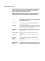
This manual includes the following sections:
Introduction
The introduction provides an overview of LTO and Ultrium technology,
and summarizes the drive’s key features, technical specifications and
Management/Diagnostic Software.
Specifications
This section contains detailed drive and cartridge specifications, as
well as a summary of regulatory approvals and compatibility with
various hardware and software.
Installation
The installation section includes handling precautions, unpacking tips,
and installation instructions for the internal and external drives, as well
as a summary of cabling and connector specifications.
Operation and
maintenance
This section explains the use and operation of the drive and describes
maintenance procedures, including drive "parking" and emergency
cartridge removal.
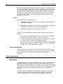
Theory of operation
This section summarizes the technology used in various drive
components.
SCSI interface
This section provides general information about the drive’s SCSI
interface.
Fibre Channel
Interface
This section provides general information about the drive’s Fibre
Channel interface.
Ultrium tape format
This section summarizes the features and technical characteristics of
the LTO tape format.
Customer support
services
This section lists service and support programs to ensure customer
satisfaction, including Internet web addresses, telephone numbers and
fax numbers.
Contents
i
Contents
Introduction
1
About the Ultrium tape format ..................................................................................... 1
About the Viper 200..................................................................................................... 2
Features and benefits ........................................................................................... 3
Specification summary.......................................................................................... 4
Management/diagnostic software......................................................................... 5
Specifications
6
Physical specifications ................................................................................................ 6
Power specifications.................................................................................................... 9
Voltage and current .............................................................................................. 9
Power dissipation.................................................................................................. 9
Drive performance specifications .............................................................................. 10
Environmental requirements ..................................................................................... 11
Injected noise...................................................................................................... 11
Reliability ................................................................................................................... 11
Mean time between failures................................................................................ 12
Mean time to repair ............................................................................................. 12
LTO cartridge specifications...................................................................................... 12
Environmental considerations ............................................................................ 12
Cartridge memory ............................................................................................... 13
Cartridge reliability .............................................................................................. 13
Regulatory compliance.............................................................................................. 13
Safety compliance .............................................................................................. 13
Electromagnetic compatibility (EMC).................................................................. 14
Hardware and software compatibility ........................................................................ 15
Compatible operating systems ........................................................................... 15
Compatible native backup software.................................................................... 15
Compatible network backup software................................................................. 15
Installation
16
Introduction................................................................................................................ 16
Unpacking and inspection ......................................................................................... 16
Guidelines and cautions ............................................................................................ 16
ii
Viper 200 LTO Product Manual
Installing an internal HVD or LVD Viper drive ...........................................................17
1. Configuring an internal HVD or LVD drive ......................................................17
2. Mounting an internal HVD or LVD drive..........................................................18
3. Connectors and cables ...................................................................................19
Installing an internal Fibre Channel Viper drive ........................................................23
1.
Configuring an internal Fibre Channel drive ..........................................23
2.
Jumper settings......................................................................................23
3.
Mounting the internal drive.....................................................................24
4.
Connectors and cables ..........................................................................25
Installing an external Viper drive ...............................................................................27
1. Configuring an external drive ..........................................................................27
2. Connecting the SCSI interface cable..............................................................27
3. Connecting the power cord .............................................................................28
Operation and maintenance
29
Front panel display ....................................................................................................29
Using LTO cartridges.................................................................................................31
Loading a cartridge .............................................................................................31
Unloading a cartridge..........................................................................................31
Write-protecting a cartridge.................................................................................31
Cartridge care and maintenance ........................................................................32
Drive maintenance.....................................................................................................33
Cleaning the tape drive .......................................................................................33
Parking the drive for shipping....................................................................................34
Parking the drive using the load/unload button...................................................34
Parking the drive using software.........................................................................34
Emergency reset and emergency cartridge eject......................................................35
Manual cartridge removal ..........................................................................................35
Before you start...................................................................................................35
Case 1: Cartridge is loaded and seated .............................................................36
Case 2. Cartridge is loaded and seated and tape is threaded ...........................38
Theory of operation
42
Track layout ...............................................................................................................42
Recording method .....................................................................................................43
Data buffer .................................................................................................................43
Data integrity..............................................................................................................43
Error-correction code (ECC) ...............................................................................43
Servo-tracking faults ...........................................................................................44
Data compression......................................................................................................44
Contents
iii
Background......................................................................................................... 44
Intelligent data compression ............................................................................... 45
Interfaces
47
Parallel SCSI interface .............................................................................................. 47
SCSI message codes ......................................................................................... 47
SCSI-2 ANSI X3.131, 1994 conformance statement ......................................... 47
Fibre Channel interface ............................................................................................. 48
Commands ................................................................................................................ 48
General Features................................................................................................ 48
Tape Alert flags................................................................................................... 50
Typical system configurations ................................................................................... 50
Ultrium tape format
52
Overview of LTO tape formats .................................................................................. 52
Ultrium technology overview ..................................................................................... 53
The Ultrium cartridge .......................................................................................... 53
Customer support services
55
World-wide services: ................................................................................................. 55
Regional services ...................................................................................................... 55
Support services in the Americas.............................................................................. 55
Support services in Europe ....................................................................................... 57
Support services for Africa and the Middle East ....................................................... 57
Support services in Asia and the Western Pacific .................................................... 57
iv
Viper 200 LTO Product Manual
Figures
Figure 1. Internal HVD/LVD Viper drive—dimensions .....................................................................................7
Figure 2. Internal Fibre Channel Viper drive—dimensions ..............................................................................8
Figure 3. Back view of the Viper 200 internal drive, showing jumper settings ...............................................18
Figure 4. Acceptable mounting orientations for the internal Viper 200 ..........................................................19
Figure 5. Back view of the Viper 200 internal LVD/HVD drive, showing connectors .....................................20
Figure 6. Two SCSI termination examples for internal Viper drive ................................................................21
Figure 7. Connectors and jumpers on the back of the Viper 200 Fibre Channel drive ..................................23
Figure 8. Assigned loop identifier jumper pins for the internal FC Viper 200.................................................23
Figure 9. Acceptable mounting orientations for the internal Viper 200 ..........................................................24
Figure 10. Rear view of the Viper 200 FC internal drive showing fibre channel optical connectors..............25
Figure 11. Rear view of the Viper 200 FC internal drive showing fibre channel optical connectors..............26
Figure 12. Back of external Viper 200 showing switches and connectors .....................................................27
Figure 13. SCSI termination examples for external tape drives.....................................................................28
Figure 14. Generic front panel display for Viper 200......................................................................................29
Figure 15. Ultrium cartridge showing write-protect switch..............................................................................31
Figure 16. Diagram of Viper 200 showing leader pin inside LTO cartridge ...................................................36
Figure 17. Diagram of Viper 200 showing worm gear ....................................................................................37
Figure 18. Diagram of Viper 200 showing key components used in manual cartridge removal ....................38
Figure 19. Diagram of Viper 200 showing lead screw (tape threaded on take-up reel).................................39
Figure 20. Diagram of underside of Viper 200 showing supply motor access hole .......................................39
Figure 21. Diagram of underside of Viper 200 showing tape grabber near cartridge ....................................40
Figure 22. Diagram of Viper 200 showing worm gear ....................................................................................40
Figure 23. Layout of tracks on LTO Ultrium tape ...........................................................................................42
Figure 24. Ultrium cartridge ............................................................................................................................52
Figure 25. LTO cartridge with door open to show leader pin .........................................................................53
Figure 26. LTO cartridge showing cartridge memory and write-protect switch..............................................54
Introduction
1
1
Introduction
About the Ultrium tape format
The Viper® 200 complies with the LTO Ultrium 8-channel format specification U-18.
The Ultrium tape format is specifically designed for maximum data storage capacity.
The Ultrium format achieves this high capacity by using long (600-meter) and wide
(1/2-inch) tape media. Data is recorded in 384 tracks, grouped in four bands, each
bounded by two servo tracks, for extreme reliability.
The Ultrium tape cassette uses just one tape reel, instead of two. This maximizes
the amount of tape that can fit in a single cartridge, since space within the cartridge
is taken up by the tape, not by tape reels. Despite its ultra-high capacity, the Ultrium
cartridge is thinner than other existing single-reel cartridges. It measures about 4
inches square and is a little more than 3/4 of an inch thick. For more information,
see “Ultrium Tape Format“ on page 45.
Open format, open opportunities
One of the missions of LTO technology was to provide an open-format specification
where multiple manufacturers could obtain a license, providing the foundation for
new, improved Ultrium products. This goal has been reached, with more than 25
licensees supporting the Ultrium format.
The key advantages of a dynamic open format include the following
•
Multiple independent technology sources
•
Extensive industry support from manufacturers, OEMs and automation suppliers
•
Shorter technology-development cycles
•
Greater competition, increasing innovation and value.
2
Viper 200 LTO Product Manual
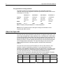
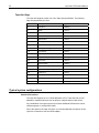
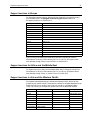
Four generations of storage solutions
The Ultrium format of LTO technology defines a four-generation technology
roadmap, which provides aggressive, attainable specifications based on the current
technologies in use today.
Generation 1
Generation 2
Generation 2
Generation 4
Capacity
200 Gbytes
400 Gbytes
800 Gbytes
1,600 Gbytes
Speed
Up to 40
Mbytes/sec
Up to 80
Mbytes/sec
Up to 160
Mbytes/sec
To 320
Mbytes/sec
Media
MP
MP
MP
Thin Film
Encoding
RLL 1,7
PRML
PRML
PRML
Note 1. Capacity and speed based on 2:1 data compression
Note 2. The LTO partners reserve the right to change the information in this
migration path without notice.
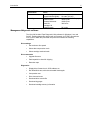
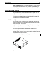
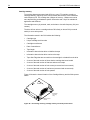
About the Viper 200
The Viper 200 is a high-performance eight-channel LTO tape drive that uses ½-inch
Ultrium tape cartridges with a native capacity of up to 100 Gbytes (for a 609m tape).
It supports Read While Write (RWW) and intelligent hardware data compression as
well as cartridge soft load. The drive’s native sustained user data transfer rate is 16
Mbytes per second. The tape capacity and transfer rate are maximized through the
use of intelligent data compression. The Viper 200 design is well suited for midrange to high-end servers, mainframe systems, and tape library automation
systems.
The Viper 200 comes with an ULTRA SCSI LVD, HVD or Fibre Channel 1 GHz
interface, as well as a serial library interface. For more information on these
interfaces, see "Installation” beginning on page 16 of this manual. The internal Viper
200 drives (STU42001LW, STU42001WD, and STU42001FC) are designed to fit in
a 5¼-inch full-height drive bay. The external drives (STU62001LW and
STU62001WD) are standalone subsystems with built-in power supplies. The table
below shows the model numbers for the different drive configurations.
Model
STU42001LW
STU42001WD
STU42001FC
STU62001LW STU62001WD
Mounting
Internal
Internal
Internal
External
External
Interface
LVD
HVD
LC Optical
Multimode
1GHz
LVD
HVD
Introduction
3
Features and benefits
The following table summarizes the features and benefits of the Viper 200 drives.
Features
Benefits
Performance
32 Mbyte-per-second compressed
transfer rate
Highest announced rate, over 115 Gbytes per hour
compressed
FastSense™
Optimization of data transfers resulting in shorter
backup times and increased reliability due to fewer
stops and starts
Intelligent Data Compression
Maximizes performance and capacity by analyzing
compressibility prior to recording
Multiple interface options:
LVD, HVD, Fibre Channel
Provides maximum flexibility to system integrators
allowing optimization of the Viper 200 drive and
their system
Fast Search
Tape search speeds between 6 and 9 meters per
second, equating to average time to file between
32 and 48 seconds
Cartridge Memory
Enables fast loading of cartridges; stores pertinent
information regarding the media
64-Mbyte data buffer
Extra fast backups on high-performance systems
Reliability
Tape Alert drive performance
monitoring and reporting
rd
Remote monitoring of device performance
3 generation read channel
Increased maturity and data integrity
Patented head positioner
Increased data integrity
Shock dampened isolated chassis
Increased shock tolerance and reliability
Managed airflow dynamics with
isolated HTI chamber
Increased data integrity and reliability through
decreasing contaminants
17
Hard error rate of 1 in 10
bits
Built-in reliability
Two levels of ECC
Extra data safety and protection from errors
Reliable tape picking implementation
Increased reliability and proof of strong engineering
Electrical
Very low RF emissions
Ease of agency certifications
Low power consumption
Typically only 23 to 34 watts operating range
Low heat rating
Increased reliability
Controlled tape path during power
interruption
Disaster avoidance technology; saves data during
unplanned power outages and prevents
unnecessary field service
Software / Firmware / Interface
Custom designed LSI circuitry
Seagate-designed and tested for fast, efficient data
processing
RISC processors
Fast, efficient data processing
Second generation LVD firmware
Mature SCSI firmware decreases the number of
revisions, increasing the ease of ongoing
qualifications
4
Viper 200 LTO Product Manual
Features
Benefits
Supports native firmware of a wide
variety of UNIX platforms
Reduced set-up and configuration time
Support for Ultra SCSI-2
Low Voltage Differential,
High Voltage Differential, and
Fibre Channel interfaces
Compatible with the today’s and tomorrow’s highperformance interfaces
Remote diagnostics
Increases data safety through monitoring and
testing capabilities; Individual feature set or private
label capabilities for each system OEM and
automation manufacturer
Support for SCSI-2 and some SCSI-3
instructions
Extra control of drive from the host system
Specification summary
Specification
Value
Tape Format
Capacity
LTO (Ultrium)
100 Gbytes (native)
609m cartridge
50 Gbytes (native)
319m cartridge
30 Gbytes (native)
203m cartridge
10 Gbytes (native)
87m cartridge
16 Mbytes per second (native) with FastSense™
Dynamically adjustable to: 14, 12, 10, 8 Mbytes /second
Internal - LVD: STU42001LW; HVD: STU42001WD
External - LVD: STU62001LW; HVD: STU62001WD;
Fibre Channel: STU42001FC
5.25” Full-Height (internal drive)
LVD
HVD
Fibre Channel – LC Optical Multimode
RS-422 Serial Port
4 meters per second at 16 Mbytes per second
4 meters per second
Heads:
8 channel
Recording Density:
93K fci
Data Density:
124K bpi
Data Tracks:
384
Data Track Density:
768 tracks per inch
Servo Tracks:
5
Less than one error in 1017 bits read (w/error correction)
(Error rate before ECC: 6 errors in 107 bits read)
Idle (tape loaded):
14 watts
Streaming RWW:
25 watts
Ramp up (peak):
35 watts (0.8 sec)
Ramp down (peak):
27 watts (0.8 sec)
Load/Unload (peak):
15 watts (0.2 sec)
Thread/Unthread
23 watts (0.2 sec)
(peak):
Idle (tape loaded):
19 watts
Streaming RWW:
25 watts
Ramp up (peak):
35 watts (0.8 sec)
Ramp down (peak):
27 watts (0.8 sec)
Performance
Models
Form Factor
Interfaces
Tape Speed
Search Speed
Recording
Error Rate
Power Consumption
(typical) Ultra 2
SCSI LVD, Ultra
SCSI HVD
Power Consumption
(typical) Fibre
Channel
Introduction
5
Specification
Reliability
Value
Load/Unload (peak):
Thread/Unthread (peak):
MTBF:
Loads/Unloads:
Threads/Unthreads:
Head Life:
Cartridge Life
Loads/Unloads:
15 watts (0.2 sec)
23 watts (0.2 sec)
250K hrs @ 100% Duty cycle
300K cycles
100K cycles
30K hours
5K cycles
Management/diagnostic software
The Viper 200 includes Tape Diagnostic Utility software for Windows, Linux and
Solaris. Enabling diagnostics both locally and remotely via TCP/IP, this software
runs in GUI or batch file (command line) mode and includes the following
capabilities:
Drive settings
• Set maximum drive speed
•
Select data compression mode
•
Select cartridge autoload mode
Drive commands
• Upgrade firmware
•
Park/unpark drive head for shipping
•
Retension tape
Diagnostics
• Display drive firmware level, SCSI address, etc.
•
Run Read-Write test, with user-selectable data lengths
•
Compression test
•
Drive electronics test
•
Download drive trace buffer
•
Download log pages
•
Download cartridge memory information
6
Viper 200 LTO Product Manual
2
Specifications
This chapter provides technical specifications for the internal and external SCSI
drives. This information covers the following specifications and requirements:
•
Physical specifications
•
Power requirements
•
Drive performance specifications
•
Environmental requirements
•
Reliability
•
Ultrium cartridge specifications
•
Regulatory compliance
•
Hardware and software compatibility
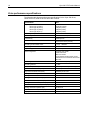
Physical specifications
The physical specifications of the Viper 200 drives are listed in the following table:
Specification
Internal SCSI drive
without bezel
Height
3.25 inches
(82.6 mm) max
5.75 inches
(146.05 ± 0.25 mm)
8.06 inches
(205 mm) max
6.2 lb. (2.82 kg)
Width
Length
Weight
Notes:
1
2
Internal Fibre
Channel drive
without bezel
3.25 inches
(82.6 mm) max
5.75 inches
(146.05 ± 0.25 mm)
10.50 inches
(267 mm) max
5.8 lb. (2.64 kg)
Internal SCSI drive External SCSI
with bezel
drive
3.32 inches
(84.26 mm)
5.82 inches
(147.75 mm)
8.62 inches
(219 mm) max
6.5 lb. (2.95 kg)
6.8 inches1
(172.7 mm)
7.61 inches
(193.3 mm)
12.17 inches2
(309.1 mm)
14.5 lb (6.58 kg)
Includes rubber feet (case alone is 6.44 inches high)
Includes front bezel and fan grill (case alone is 11.9 inches long)
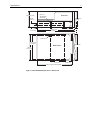
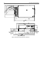
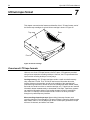
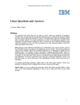
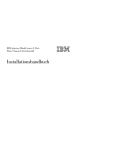
Figures 1 and 2 on the following pages show the dimensions of the internal Viper
200 drive with HVD/LVD and Fibre Channel Interfaces, respectively.
Specifications
7
82.6 mm (max)
21.80
± 0.20 mm
9.90
± 0.20 mm
M3 X 5.0
4X Near side
4X Far side
Side View
84.26 mm
(max)
79.24 ± 0.20 mm
210.41 mm
219.00 mm max
48.9
± 0.20 mm
4X M3 X 5.0
139.70 mm
± 0.20 mm
147.75 mm
Bottom View
146.05
± 0.25 mm
79.24
± 0.20 mm
205 mm (max, without bezel)
Figure 1. Internal HVD/LVD Viper drive—dimensions
48.9
± 0.20 mm
8
Viper 200 LTO Product Manual
Figure 2. Internal Fibre Channel Viper drive—dimensions
Specifications
9
Power specifications
The external Viper 200 drives (STU62001LW and STU62001WD) come with a builtin 90-260VAC (47-63 Hz) automatic switching power supply.
Maximum voltage and power specifications for the internal Viper 200 drives
(STU42001LW, STU42001WD, and STU42001FC) are listed in the tables below.
Specifications are the same for SCSI and Fibre Channel drives unless otherwise
noted.
Voltage and current
Specification
+12 VDC
+5 VDC
DC Voltage Tolerance
+ or – 10%
+ or – 5 %
Non-operating max voltage
14 Volts peak
7 Volts peak
Max Operating current
Continuous:
Ultra2 SCSI LVD; Ultra SCSI HVD
Fibre Channel
1.0 amps RMS
1.0 amps RMS
3.5 amps max RMS*
4.0 amps max RMS*
3.0 amps
(1 sec max)
NA
Peak:
Standby current (max)
Ultra2 SCSI LVD; Ultra SCSI HVD
Fibre Channel
0.5 amps RMS
0.5 amps RMS
2.0 amps RMS*
2.5 amps RMS*
Ripple (peak-to-peak)
≤ 100 mV
≤ 100 mV
Power dissipation
Specification
Value
Max Standby Power
Ultra2 SCSI LVD; Ultra SCSI HVD
Fibre Channel
14 watts RMS*
19 watts RMS*
Max Continuous Operating Power
Ultra2 SCSI LVD; Ultra SCSI HVD
Fibre Channel
30 watts RMS*
32.5 watts RMS*
Max Peak Operating Power
Ultra2 SCSI LVD; Ultra SCSI HVD
Fibre Channel
48.5 watts (1 sec max)
58.5 watts RMS
* RMS parameters measured at the power connector using a true RMS digital
meter.
10
Viper 200 LTO Product Manual
Drive performance specifications
The following table lists the performance specifications for the Viper 200 drives,
Ultra2 SCSI LVD, Ultra SCSI HVD and Fibre Channel.
Specification
Value
Capacity
Ultrium type A (609 m)
Ultrium type B (319 m)
Ultrium type C (203 m)
Ultrium type D (87 m)
100 Gbytes (native)
50 Gbytes (native)
30 Gbytes (native)
10 Gbytes (native)
Recording density
3,660 RLL-encoded ONEs per mm
Flux density
3,660 flux transitions per mm
Track density
3 tracks per mm
Error recovery
Read-after-write
Reed Solomon ECC (2 levels)
Recording unrecoverable errors
< 1 in 1017 data bits
Recording undetectable errors
< 1 in 1027 data bits
Tape drive type
LTO (Ultrium)
Head configuration
16 thin-film write heads
16 MR read heads
8 MR servo heads
During operation 8 write heads, 8 read
heads and 2 servo heads are active at the
same time.
Recording format
Ultrium 8-channel (U-18)
Recording method
(1,7) RLL
Transfer rate (sustained)
16.137 Mbytes/second (max, native)
Synchronous transfer rate (burst)
80 Mbytes per sec max
Asynchronous transfer rate (burst)
40 Mbytes per sec max
Cartridge load and tape thread time
<10 seconds
Cartridge unload time
3 seconds
Average rewind time (609-m tape)
< 76 seconds
Maximum rewind time (609-m tape)
152 seconds
Average data access time (609-m tape)
< 76 seconds
Maximum data access time (609-m tape)
152 seconds
Average rewind time (609-m tape)
< 76 seconds
Maximum rewind time (609-m tape)
152 seconds
Tape speed
up to 4 meters per second
Specifications
11
Environmental requirements
The following table lists the environmental specifications for the SCSI and Fibre
Channel Viper drive mechanisms.
Specification
Operational
Non-operational
Temperature
+50° to +104°F
(+10° to + 40°C)
–40° to +149°F
(–40° to + 66°C)
Airflow requirements
Internal: 9 CFM (front to back)
NA
Thermal gradient
11°C per hour (10-40°C)
11°C per hour (10-40°C)
Relative humidity
20% to 80% non-condensing
10% to 95% non-condensing
Humidity gradient
10% per hour
10% per hour
Maximum wet bulb temp.
78.8°F (26°C)
No condensation
Altitude
max 10,000 feet MSL (at 25°C)
40,000 feet (power off)
Shock (1/2 sine wave)
10 Gs peak, 11 msec
40 Gs peak, 11 msec
Vibration (Sweep Test)
0.005 inches DA (5-43 Hz)
0.50 G peak (43–1000 Hz)
sweep rate 5-1000Hz;
0.25 octave per minute)
1.0 G (5-500Hz;
sweep rate 1.0 octave per
minute)
Acoustic level idling
(A-wt sum)
38 dBA maximum
5.0 LwA Bels
—
Acoustic level operational
(A-wt sum)
41 dBA maximum
5.5 LwA Bels
—
Injected noise
The internal drive will operate without degradation of error rates with 100 mV of
noise injected between the chassis and 0 V at the power connector at any frequency
between 45 Hz and 10 MHz.
Reliability
The Viper drive is designed for maximum reliability and data integrity. The following
table summarizes the reliability specifications.
Specification
Description
Non-recoverable error rate
< 1 in 10
Error recovery and control
- Error-correction code techniques (C1 and C2 ECC)
- Read-after-write (RAW)
- Error monitoring and reporting (error log)
- Retry on read
Mean time between failures
(MTBF)
250,000 hours MTBF at 100% duty cycle: power
applied and tape moving continuously
(External drive; 50,000 hours at full load and 25°C)
Cartridge load/unload into drive
300,000 cartridge load/unload cycles (no thread)
Mean time to repair (MTTR)
Less than 0.5 hour
17
bits
12
Viper 200 LTO Product Manual
Mean time between failures
The mean time between failures (MTBF) for the internal drive is specified at 250,000
hours minimum. This specification includes all power-on and operational time but
excludes maintenance periods. Operational time is assumed to be 100 percent of
the power-on time. Operational time is the time the tape is loaded.
The MTBF for the external drive power supply is 50,000 hours with the unit operated
at full load and 25°C.
Note.
The MTBF rating does not represent any particular drive, but is derived from
a large database of test samples. Actual rates may vary from unit to unit.
Mean time to repair
The mean time to repair (MTTR) is the average time required by a qualified service
technician to diagnose a defective drive and to install a replacement drive. The
MTTR for LTO products is less than 0.5 hour (30 minutes).
The Seagate LTO drives are field-replaceable units. If a problem occurs with a
subassembly or component in the drive, you should replace the entire unit. Return
the drive to the factory in its original packaging. Contact your distributor, dealer, your
computer system company or your Seagate sales representative to arrange the
return.
LTO cartridge specifications
Environmental considerations
The table below lists the basic environmental tolerances for LTO Ultrium cartridges.
Specification
Value
Operating temperature
10°C to 45°C
Relative Humidity
10% to 80%
Wet Bulb Temperature
26° C max
Max Localized Temperature-permanent tape damage
> 52°C
If during storage and/or transportation a cartridge has been exposed to conditions
outside the above values, it must be conditioned before use in the operating
environment. The conditioning shall be exposure to the operating environment for a
time equal to, or greater than, the time away from the operating environment, up to a
maximum of 24 hours. There shall be no deposit of moisture anywhere on or in the
cartridge.
The stray magnetic field at any point on the tape shall not exceed 4000 A/m.
Specifications
13
Cartridge memory
Each Ultrium 1 cartridge has 4 Kbytes of nonvolatile memory: 3 Kbytes are used to
store tape-directory and hardware specific information. 1 Kbyte is available for
application and OEM use. The cartridge memory is powered, read, and written to via
a radio-frequency link.
Cartridge reliability
Recommended cartridge use: After 5,000 load/unload cycles, replace the cartridge
to insure data integrity.
See the Ultrium Tape Format section of this manual for additional cartridge
information and illustrations.
Regulatory compliance
These drives comply with the safety and EMC regulations listed in the following
tables.
Safety compliance
Country
United States
Canada
Germany
Mexico
Singapore
South Korea
Argentina
China
EU member
nations
Member
Nations of
the IECEE*
Hungary
Czech
Republic
Poland
Russia
Bulgaria
Malaysia
Regulatory Organization
Underwriters Laboratories (UL)
Canadian Standards Association
(CSA)
Technischer Überwachungs-Verein
(TUV) Rheinland
Normas Oficiales Mexicanas (NOM),
similar to UL
Productivity and Standards Board
(PSB)
JEON
Instituto Argentino de Racionalization
de Materiales (IRAM)
Chinese Commodity Import Bureau
(CCIB)
Comité Europèen de Normalisation
Electrotechnique – the European
Committee for Electrotechnical
Standardization (CENELEC)
International Electrotechnical
Commission on Electrical Equipment
(IECEE) for Mutual Recognition of
Test Certificates for Electrical
Equipment "CB Scheme"
MEEI Budapest
EZU Praha
PCBC BBJ-SEP
GOSSTANDART (GOST)
CSM
JBE SIRIM
Compliant to:
UL 1950 – 3 edition
CSA 22.2 950-95
rd
IEC 950 / EN60950, (including
amendments A1, A2, A3, A4,
A11)
NOM standards
PSB safety certification
JEON safety certification
IRAM safety certification
CCIB safety certification
IEC 950 / EN60950 (including
amendments A1, A2, A3, A4,
A11)
CB Scheme per IEC 950 /
EN60950 with details and
exceptions for each member
country
CB Scheme
CB Scheme
CB Scheme
CB Scheme
CB Scheme
CB Scheme
14
Viper 200 LTO Product Manual
Country
Thailand
India
South Africa
Israel
Regulatory Organization
TISI
STQC BIS
SABS
SII
Compliant to:
CB Scheme
CB Scheme
* Member nations of the IECEE include Austria, Australia, Belgium, Canada, China
(PR), Czech Republic, Denmark, Finland, France, Germany, Hungary, India, Ireland,
Israel, Italy, Japan, (South) Korea, Netherlands, Norway, Poland, Russian
Federation, Singapore, Slovakia, Slovenia, South Africa, Spain, Switzerland, United
Kingdom, USA, Yugoslavia.
Electromagnetic compatibility (EMC)
Country
United States
Regulatory Organization
Federal Communications
Commission (FCC)
Canada
Industry Canada Digital Apparaus Interference-Causing Equipment
Standard (ICES-003)
CE
EU member
nations
Australia &
New Zealand
Japan
Standards Australia Spectrum
Management "C-Tick"
Voluntary Control Council for
Interface (VCCI)
South Korea
Taiwan
Radio Research Lab of Korea (RRL)
Bureau of Commodity Inspection and
Quarantine (BSMI)
Chinese Commodity Import Bureau
(CCIB)
PREDOM-OBR
GOSSTANDART (GOST)
CSM
SII
China
Poland
Russia
Bulgaria
Israel
Note:
Compliant to:
Title 47: Code of Federal
Regulations, Part 15, Subpart
B, Class B: Digital Device
(47CFR15B)
ICES-003 Class B: Digital
Apparatus
Emissions per CISPR 22:1997
- EN55022:1998 and Immunity
per CISPR 24:1997 EN55024:1998
AS/NZS 3548-1995 (same as
CISPR 22)
This is a voluntary compliance
standard; the drives meet it via
CE compliance
RRL EMC certification
BSMI EMC certification
CCIB EMC certification
CISPR-22, Class B
CISPR-22, Class B
CISPR-22, Class B
CISPR-22, Class B
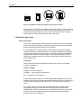
Use these drives only in equipment where the combination has been
determined to be suitable by an appropriate certification organization (for
example, Underwriters Laboratories Inc. or the Canadian Standards
Association in North America).
You should also consider the following safety points:
•
Install the drive in an enclosure that limits the user’s access to live parts, gives
adequate system stability and provides the necessary grounding for the drive.
•
Provide the correct voltages (+5 VDC and +12 VDC) based on the regulation
applied—Extra Low Voltage (SEC) for UL and CSA, and Safety Extra Low
Voltage for BSI and VDE (if applicable).
Specifications
15
Hardware and software compatibility
Compatible operating systems
The Viper 200 is compatible with the following operating systems running on an
Intel-based system.
•
Microsoft Windows NT (Windows 2000)
•
Novell NetWare 5.0 and 5.1
•
Red Hat Linux 6.2
•
SCO OSR 5.0.5, 5.0.6
•
SCO Unixware 7.1
Compatible native backup software
The Viper 200 is compatible with the native backup software provided with the
following operating systems:
Compaq Tru64
Microsoft NT 4.0/Win2000
SCO UnixWare 7.1
DEC VMS, UNIX, Ultrix, OSF1
Novell NetWare 5.0 and 5.1
SGI Irix 6.6 and later
HP/UX 11.2 and later
Red Hat Linux 6.2
SunOS 4.3 and later
IBM AIX 4.3 and later
(including Monterey)
SCO Unix 5.0.5
Sun Solaris 2.6 and later
Compatible network backup software
The Viper 200 is compatible with the following network backup utility software (ISV
certifications).
ADSM Backup
HP Omniback
SCH Technologies Robot
Bakbone NetVault
BEI UltraBAc
IBM Tivoli
Legato Celestra
Sunsoft Solstice (Legato)
Syncsoft Backup Express
CA ArcServe
Legato Networker
Veritas Backup
CA Sterling
Linux EST BRU2000
Veritas NetBackup
Cristie PCBax
OTG Software Inc. Xtender
Yosemite TapeWare
Dantz Retrospect
SCH Technologies RBU
EMC Symmetrix
SCH Technologies RLB
16
Viper 200 LTO Product Manual
3
Installation
Introduction
This chapter explains how to install the Viper 200 internal and external drives. It
includes the following sections
•
Unpacking and inspection: contains general information that you should read
before installation.
•
Guidelines and cautions: guidelines and cautions for handling and installing
internal tape drives.
•
Installing an internal HVD/LVD Viper drive: describes installing the internal
drive in a 5.25-inch drive bay.
•
Installing an internal Fibre Channel Viper drive
•
Installing an external Viper drive: describes installing an external drive.
Unpacking and inspection
Although drives are inspected and carefully packaged at the factory, damage may
occur during shipping. Follow these steps for unpacking the drive.
1.
Visually inspect the shipping containers and notify your carrier immediately of
any damage.
2.
Place shipping containers on a flat, clean, stable surface; then carefully remove
and verify the contents against the packing list. If parts are missing or the
equipment is damaged, notify your Seagate representative.
3.
Always save the containers and packing materials for any future reshipment.
Guidelines and cautions
The following guidelines and cautions apply to handling and installing internal tape
drives. Keep them in mind as you install the drive.
•
Handle the drive by the sides rather than by the top cover to reduce the risk of
dropping the drive or damaging it during installation.
•
Internal drives contain some exposed components that are sensitive to static
electricity. To reduce the possibility of damage from static discharge, the drives
are shipped in a protective antistatic bag. Do not remove the drive from the
antistatic bag until you are ready to install it.
Installation
17
•
Before you remove the drive from the antistatic bag, touch a metal or grounded
surface to discharge any static electricity buildup from your body.
•
Always lay the drive either on top of the antistatic bag or place it inside of the
bag to reduce the chance of damage from static discharge.
•
Install HVD drives only in an HVD environment, Fibre Channel drives only in a
Fibre Channel environment, and LVD drives only in an LVD environment. Do not
mix HVD and LVD devices on the same SCSI bus. Look at the label above the
drive’s SCSI connector to determine if the drive is an HVD or an LVD model
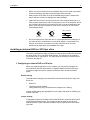
(see examples below:
SCSI
LVD/SE
LVD label
•
SCSI
DIFF
Fibre Channel
HVD label
Due to the speed of the Viper 200 drive, it is recommended that a maximum of
two Viper drives be connected to one host SCSI adapter. In a switched Fibre
Channel environment, the maximum number of drives that can be used
simultaneously depends on the bandwidth of the loop.
Installing an internal HVD or LVD Viper drive
This section describes the steps necessary to install an internal Viper 200 drive with
an Ultra2 SCSI LVD or Ultra SCSI HVD interface. For instructions on installing a
Fibre Channel drive, see page 23. For instructions on installing an external HVD or
LVD drive, see page 27.
1. Configuring an internal HVD or LVD drive
Before you install the tape drive in your computer, you may need to configure the
drive’s SCSI ID and other drive features. Jumpers located on the back of the drive
(near the left edge) are used to configure the SCSI ID and to enable termination
power.
Default settings
The default drive settings for the Ultra2 SCSI LVD and Ultra SCSI HVD Viper 200
drives are:
•
SCSI ID 6
•
Termination power disabled
(configuration may vary if purchased as a component of a Library).
If these default settings are appropriate for your needs, skip ahead to “Mounting an
internal Viper 200.”
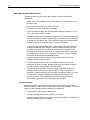
Jumper settings
Configuration jumpers on the back of the Parallel SCSI drive control the drive’s SCSI
ID and SCSI termination power. The jumpers can also be used for remote SCSI
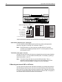
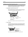
address selection. Figure 3 shows the locations of the jumper blocks for the internal
Viper 200.
18
Viper 200 LTO Product Manual
Jumper Settings:
Drive-configuration jumper pins
Default
settings:
Pins: Function:
1-2 SCSI ID bit 0
3-4 SCSI ID bit 1
5-6 SCSI ID bit 2
7-8 SCSI ID bit 3
9-10 Reserved
11-12 Termination Power
SCSI ID=0
SCSI ID=8
SCSI ID=1
SCSI ID=9
SCSI ID=2
SCSI ID=10
SCSI ID=3
SCSI ID=11
SCSI ID=4
SCSI ID=12
SCSI ID=5
SCSI ID=13
SCSI ID=6
SCSI ID=14
SCSI ID=7
SCSI ID=15
Term. power
Figure 3. Back view of the Viper 200 internal drive, showing jumper settings
SCSI Address Selection (pins 1 through 8)
You can select the SCSI address used by the drive by placing the appropriate
jumpers on pin-pairs 1-2 through 7-8, as shown in Figure 1.
Note:
Each SCSI device on a bus must have a unique SCSI ID. The SCSI
controller or host adapter generally uses ID 7. In some systems, the boot
drive uses ID 0 or ID 1.
Terminator power (pins 11 and 12)
Internal HVD and LVD Viper 200 drives are shipped with terminator power disabled,
as shown in Figure 1. You can enable terminator power, if necessary, by placing a
jumper across pins 11 and 12.
Note:
The internal Viper 200 does not provide SCSI termination. Thus, a
terminator must be installed on the drive if it is the last device in a SCSI
chain. See “SCSI termination” on page 21 for more information.
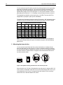
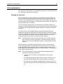
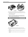
2. Mounting an internal HVD or LVD drive
You can mount the internal Viper 200 either horizontally or vertically with the drives
left side facing up (see Figure 4). If a drive is mounted vertically, the left side of the
drive must face up and the side of the drive should be within 5 degrees of horizontal.
If a drive is mounted horizontally, the base of the drive must be within 15 degrees of
horizontal and the PCB side of the drive must face down.
Installation
19
YES
YES
NO
NO
Figure 4. Acceptable mounting orientations for the internal Viper 200
Mount the drive in a 5.25-inch, full-height drive bay and secure it using two M3.0 X 5
metric screws on each side of the drive. Do not use screws longer than 5 mm or you
may damage the drive. Figure 1 on page 7 shows the locations of the mountingscrew holes on the side and bottom of the drive, respectively.
3. Connectors and cables
General information
Use a 68-pin, flat cable with a maximum length of 6 meters (19 feet) to connect the
drives to the SCSI host adapter. If twisted-pair cabling is used, connect the twisted
pairs to physically opposing contacts on the connector.
A SCSI standard stub no greater than 0.1 meter should be used off the mainline
connection within any connected equipment. The cable’s characteristic impedance
should be between 90 ohms and 140 ohms. A cable with characteristic impedance
of greater than 100 ohms is recommended. To minimize noise and ensure even
distribution of terminator power, the minimum recommended conductor size is 28
AWG (0.08042 mm2).
Connectors
Ultra2 SCSI LVD and Ultra SCSI HVD Viper drives use a 68 pin, non-shielded
connector, alternative 3.
Interface voltages
VTERM : 4.25 to 5.25 Volts DC
CURRENT : 1.5A minimum, 2.0A maximum
NT : 1.5A minimum, 2.0A maximum
A Viper 200 drive with an HVD or LVD interface typically operates on a daisy-chain
interface in which other SCSI devices are also operating. Devices on the daisy chain
must all operate in the same mode, either SE, LVD, or HVD but not a mixture of
these.
The LVD/SE version of the Viper 200 is LVD/SE multimode compliant in that it
automatically switches to LVD or SE as determined by the level of the SCSI
DIFFSENS line. Therefore any SE device on the daisy chain forces the entire chain
to SE mode. On the interface daisy chain, all signals are common between all
devices on the chain, or SCSI bus.
20
Viper 200 LTO Product Manual
Caution:
An HVD drive should never be plugged into a SCSI bus that contains
LVD or SE devices.
The daisy chain of SCSI devices must be terminated at both ends with terminators
of the proper impedance, in order to operate correctly. Intermediate SCSI devices
shall not be terminated. Internal Viper drives do not have onboard termination
circuits. Some type of external termination circuits must be provided for these drives
by the end user or designers of the equipment into which the drives will be
integrated.
Data transfer methods and rates for SCSI (LVD and HVD)
Interface Mode
Asynchronous
Fast-5
Fast-10
Ultra/
Fast-20
Ultra2/
Fast-40
SE
Yes
Yes
Yes
Yes
No
LVD
Yes
Yes
Yes
Yes
Yes
HVD
Yes
Yes
Yes
Yes
No
8-bit transfer rate
(Mbytes/second)
-
5
10
20
40
16-bit transfer rate
(Mbytes/second)
-
10
20
40
80
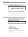
Connecting the SCSI cable
First turn off all power to the drive and computer. Then attach the interface cable to
the 68-pin SCSI interface connector on the back of the drive (see Figure 5).
Serial Interface
connector
Driveconfiguration
jumper pins
5 / 12 Volt
power
connector
68-pin
SCSI
connector
Figure 5. Back view of the Viper 200 internal LVD/HVD drive, showing connectors
Installation
21
Install an HVD drive only in an HVD environment and an LVD drive only in an LVD
environment. Do not mix HVD and LVD devices. Look at the label above the drive’s
SCSI connector to determine if the drive is an HVD or an LVD model:
HVD label:
LVD label:
FC label:
Fibre Channel
Caution.
Plugging an HVD drive into an LVD bus or vice versa will make the
entire bus non-functional and may permanently damage the drive or
other SCSI devices on the bus.
SCSI termination
The Viper 200 internal drive does not provide SCSI termination. Therefore, you must
place a SCSI bus terminator or a SCSI device with termination enabled at the end of
the SCSI chain. Two examples of SCSI termination are shown in Figure 6. The
Viper 200 does provide terminator power if a jumper is placed on the termination
power jumper, as shown in Figure 3 on page 17.
Figure 6. Two SCSI termination examples for internal Viper drive
Connecting a serial interface cable (for tape libraries)
The drive includes an RS-422 serial interface for tape libraries. The RS-422 serial
interface connector is on the lower left side of the back of the drive, as shown in
Figure 5 on the previous page.
The pin descriptions for the Serial Interface connector on the Parallel SCSI drive are
shown in the table below. The pins on this connector are set on 2-millimeter centers.
Pin numbers
Description
1 through 8
Reserved (do not use)
9
Lib RXD-P input to drive
10
GND
11
Lib RXD-N input to drive
12
GND
22
Viper 200 LTO Product Manual
13
Lib TXD-P output from drive
14
GND
15
Lib TXD-N output from drive
16
GND
Connecting a power cable
Attach a four-pin power cable to the power connector on the back of the drive.
Figure 5 on page 20 shows the location of the power connector.
The recommended 4-pin power connector for the internal Viper 200 is an AMP 148024-0 housing with AMP 60617-1 pins or equivalent.
Power connector
The following table lists pin assignments of the power connector for the internal
SCSI and Fibre Channel Viper drives.
Pin
Assignment
1
+12 VDC power
2
+12 VDC return
3
+5 VDC return
4
+5 VDC power
Installation
23
Installing an internal Fibre Channel Viper drive
This section describes the steps necessary to install an internal Viper 200 with a
Fibre Channel LC Optical (FC) interface. For instructions on installing a drive with an
Ultra2 SCSI LVD or Ultra SCSI HVD interface, see page 17. For instructions on
installing an external HVD or LVD drive, see page 27.
1. Configuring an internal Fibre Channel drive
Before you install the tape drive in your computer, you may need to configure the
drive’s hard-assigned loop identifier and other drive features. Jumpers located on
the back of the drive (see Figure 7) are used to configure the ID.
B A
4-pin power
connector
serial
interface
connector
Assigned loop identifier
jumper pins
fibre-channel
optical connectors
Figure 7. Connectors and jumpers on the back of the Viper 200 Fibre Channel drive
2. Jumper settings
Configuration jumpers on the back of the drive control the assigned loop identifier,
which the drive will attempt to acquire during the LIHA (hard address) phase of the
Loop Initialization Process (LIP). The jumpers can also be used for remote ID
selection. Figure 8 shows the location of the assigned loop identifier jumper pins on
the Viper 200 FC drive.
Assigned loop identifier
jumper pins
B A
13 11 9 7
14 12 10 8
5
6
3
4
1
2
Pin
Numbers
Figure 8. Assigned loop identifier jumper pins for the internal FC Viper 200
24
Viper 200 LTO Product Manual
You can select the hard ID used by the drive by placing jumpers on the appropriate
assigned loop identifier jumper pins. The seven sets of jumpers represent seven
binary digits, with the lowest binary weight (2^0) on the left (pins 13-14) and the
highest binary weight (2^6) on the right (pins 1-2). If a jumper is placed on a set of
pins (ON), the bit is set as a “1.” If no jumper is on a set of pins, the bit is set as “0.”
The assigned loop identifier can be set from 0 to 125 (7Eh). The Viper 200 FC is
shipped with no jumpers in place (an ID of 0000000).
The table below illustrates the system used for ID selection. “ON” indicates a jumper
installed on the pins indicated. Blank cells indicate pins without a jumper installed.
Jumper Pins (blank indicates no jumper)
Loop ID
0
1
2
3
4
5
6
….
125
13-14
11-12
9-10
7-8
5-6
ON
ON
3-4
1-2
ON
ON
ON
ON
ON
ON
ON
ON
ON
ON
ON
ON
ON
Note: Setting an invalid ID (7Fh or 7Eh) will cause the drive not to participate in
LIHA and to instead attempt to acquire an address during the LISA (soft address)
phase of LIP.
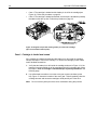
3. Mounting the internal drive
You can mount internal Viper 200 drives either horizontally or vertically with the
drives left side facing up (see Figure 9). If a drive is mounted vertically, the side of
the drive should be within 5 degrees of horizontal. If a drive is mounted horizontally,
the base of the drive must be within 15 degrees of horizontal and the PCB side of
the drive must face down.
YES
YES
NO
NO
Figure 9. Acceptable mounting orientations for the internal Viper 200
Mount the drive in a 5.25-inch, full-height drive bay and secure it using two M3.0 X 5
metric screws on each side of the drive. Do not use screws longer than 5 mm or you
may damage the drive. Figure 2 on page 8 shows the locations of the mountingscrew holes on the side and bottom of the drive.
Installation
25
4. Connectors and cables
Viper 200 drives (STU42001FC) have Fibre Channel LC Optical interfaces. They
can be connected to either a hub or a switch. Each drive contains two FC ports,
which operate independently. In systems supporting failover, this permits hosts to
maintain a connection with the drive if one connection fails.
Connecting the Fibre Channel interface cable
Viper 200 FC drives are 100-M5-SN-I compliant and use LC style connectors. Either
50 or 62.5µm multimode optical fiber cables may be used. Attach the interface cable
to either of the two LC optical interface connectors on the back of the drive (labeled
A and B in Figure 10).
In systems that support “failover,” both ports can be connected through separate
loops or fabrics to the same set of host computers. This way, if one connection fails,
the other can be used to continue the data transfer.
Fibre channel
optical connector
Figure 10. Rear view of the Viper 200 FC internal drive showing fibre channel optical
connectors
Connecting a Serial Interface Cable (for tape libraries)
The Viper 200 drive includes an RS-422 serial interface for tape libraries. The RS422 serial interface connector is on the top of the extension on the back of the drive,
as shown in Figure 11.
26
Viper 200 LTO Product Manual
Serial Interface connector
pin numbers
17 15 13 11 9 7
B A
18 16 14 12 10 8
5
6
3
4
1
2
Pin
Numbers
(Pin 17 removed to prevent
connector from being attached incorrectly)
Figure 11. Rear view of the Viper 200 FC internal drive showing fibre channel optical
connectors
Pin and signal descriptions for the Serial Interface connector are shown in the table
below. These pins are on 2-mm centers.
Pin 1 is used by the drive to detect the presence of a tape library. The serial
interface cable must connect this pin to the adjacent pin 3.
Pin number
Description
1
Library detect (cable should connect pin 1 to pin 3)
2
Lib TXn (output from drive, transmit negative)
3
GND
4
Lib TXp (output from drive, transmit positive)
5
GND
6
Lib RXn (input to drive, receive negative)
7
GND
8
Lib RXp (input to drive, receive positive)
9 through 18
Reserved (do not use)
Connecting a power cable
Attach a four-pin power cable to the power connector on the back of the drive.
Figure 7 on page 23 shows the location of the power connector on Viper Fibre
Channel drives.
The recommended 4-pin power connector for the internal Viper 200 is an AMP 148024-0 housing with AMP 60617-1 pins or equivalent.
Installation
27
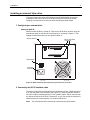
Installing an external Viper drive
The external Viper 200 drives (STU62001LW and STU62001WD) are compact
subsystems that connect to the host computer through an external SCSI port.
Installing an external drive involves the three simple steps shown below:
1. Configuring an external drive
Setting the SCSI ID
Make sure that the drive is turned off. Then set the SCSI ID for the drive using the
push-button switch on the back of the external drive, as shown in Figure 12. The
change will take effect when you turn the drive back on.
SCSI ID selector
68-pin wide SCSI
connectors
+
–
On/Off switch
AC Power
connector
Figure 12. Back of external Viper 200 showing switches and connectors
2. Connecting the SCSI interface cable
The external Viper 200 provides two 68-pin, shielded connectors (ANSI Alternative
2) on the rear panel of the enclosure (see Figure 12). These connectors consist of
two rows of ribbon contacts spaced 2.16 mm (0.085 in) apart. Either connector can
be used as a SCSI IN or SCSI OUT connection, so you can use either connector to
attach the drive to a host computer or to another SCSI device.
Note:
Turn off all power before connecting or disconnecting SCSI cables.
28
Viper 200 LTO Product Manual
SCSI termination
If the Viper drive is the last device or the only device in a SCSI chain, you must
install a terminating plug on the unused SCSI connector. See Figure 13 below for
two SCSI termination examples. You can purchase appropriate terminating plugs on
the Internet at http://buytape.seagate.com.
Note.
Termination power is enabled as a default for the external Viper 200 drive.
External
SCSI device
SCSI Terminators
External
Tape Drive
External
Tape Drive
External
SCSI device
SCSI Controller
(termination disabled)
SCSI Controller
(termination enabled)
Example 1: SCSI termination
in a system that has only
external SCSI devices.
Internal
SCSI device
(termination
enabled)
Example 2: SCSI termination
in a system that has both
internal and external SCSI
devices.
Figure 13. SCSI termination examples for external tape drives
3. Connecting the power cord
Attach the power cord securely to the power connector on the back of the drive (see
Figure 12 on the previous page).
Operation and maintenance
29
4
Operation and maintenance
This section describes important operational procedures for the Viper 200 drive. It
covers the following topics:
•
Understanding the front panel display
•
How to use LTO cartridges
•
Cleaning the tape drive
•
"Parking" the drive for shipping, resetting the drive, and emergency cartridge
removal
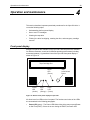
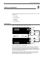
Front panel display
Multiple front panels are available for the Viper 200. Different panels are available
for different customers, as well as for different operating environments (including
automated systems). A generalized view of the Viper 200 front-panel display is
shown in Figure 14.
Tape Cartridge Slot
Power
LED
(Green)
Status
LED
(Amber)
Error
LED
(Orange)
Tape
Load/Unload
Button
Drive
LED
(Green)
Figure 14. Generic front panel display for Viper 200
All drives have four LEDs on the front panel. The functions and colors of the LEDs
are summarized in the following paragraphs.
•
Power LED (green) – The Power LED blinks during drive power-up and Poweron Self Test (POST). If there is an error during the POST, the Power LED
30
Viper 200 LTO Product Manual
remains on (not blinking), along with the Status light. During normal operation,
the Power light remains on (not blinking).
•
Status LED (amber) – If the Status LED stays on continuously, the drive needs
to be cleaned. Other changes in drive or cartridge status are indicated by
various blinking patterns, which are described in the table below.
•
Error LED (orange) – The Error light blinks if the drive experienced a nonrecoverable error.
•
Drive LED (green) – The Drive LED is lit whenever a tape is loaded and ready
for use. The Drive LED light blinks whenever a tape is loaded and moving.
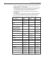
The following table summarizes all the “blink codes” used by the Viper 200.
Drive Condition
Status LED
(Amber)
ON
1/4 sec ON
1/4 sec OFF
Prevent Media Removal Mode 1/2 sec ON
Active
1/8 sec OFF
Hardware or Firmware Error
Error LED
(Orange)
Drive LED
(Green)
Cleaning Request
Write Protected
1/8 sec ON
1/8 sec OFF
Positioning – Loading,
Unloading, Rewinding,
Spacing or Locating
Tape Active – Writing,
Reading or Verifying
ON
continuously
SCSI Active
1/4 sec ON
1/8 sec OFF
1/2 sec ON
1/8 sec OFF
Manual Intervention Required 1/8 sec ON
1/8 sec OFF
Power On Self Test (POST)
ON
Failure
Excessive Rewrites or Read
C2 errors
Cleaning Cartridge Present
ON
Cleaning Cartridge at EOT
1/8 sec ON
1/8 sec OFF
1/4 sec ON
1/8 sec OFF
1/2 sec ON
1/2 sec OFF
SCSI bus reset
Servo Initialization
Power On Self Test (POST)
In Progress
Cleaning Failure
Microcode Download
Microcode Download Error
1/4 sec ON
1/4 sec OFF
1/8 sec ON
1/8 sec OFF
1/8 sec ON
1/8 sec OFF
1/8 sec ON
1/8 sec OFF
1/8 sec ON
1/8 sec OFF
1/2 sec ON
1/2 sec OFF
1/4 sec ON
1/4 sec OFF
1/8 sec ON
1/8 sec OFF
ON
ON
1/4 sec ON
1/4 sec OFF
1/8 sec ON
1/8 sec OFF
1/4 sec ON
1/4 sec OFF
1/8 sec ON
1/8 sec OFF
1/4 sec ON
1/8 sec OFF
1/2 sec ON
1/2 sec OFF
1/4 sec ON
1/4 sec OFF
ON
1/8 sec ON
1/8 sec OFF
1/8 sec ON
1/8 sec OFF
Operation and maintenance
31
Using LTO cartridges
Loading a cartridge
To load an Ultrium cartridge into the Viper 200, place the cartridge in the slot and
then push it to the detent. Then:
•
Continue to push the cartridge the rest of the way into the drive; or,
•
Press the load/unload button on the front of the drive to seat the cartridge; or,
•
Use a library or host command to finish loading the tape.
Unloading a cartridge
To unload an Ultrium cartridge from the Viper 200, either:
•
Use a library or host command to unload the tape, or
•
Push the load/unload button on the front of the drive.
Caution.
Several seconds may elapse between the time you press the
load/unload button and the time the cartridge is ejected. Do not power
down the tape drive or the host computer until the Viper 200 has
completely ejected the cartridge.
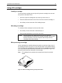
Write-protecting a cartridge
Ultrium cartridges have a sliding write-protect switch near the back right corner of
the cartridge, as shown in Figure 15. If you slide the switch to the position farthest
from the corner of the cartridge, data can be read from the cartridge but not written
to it. If you slide the switch all the way toward the corner (as shown in Figure 15),
data can be both read from and written to the cartridge.
Note.
LTO cartridges have prewritten servo patterns and should not be bulk
erased.
Writeprotect
switch
(unlocked)
Front
Locked
Unlocked
Figure 15. Ultrium cartridge showing write-protect switch
32
Viper 200 LTO Product Manual
Cartridge care and maintenance
To protect the data on your Ultrium data cartridges, observe the following
precautions:
•
Always remove the cartridge from the drive when not in use and store it in its
protective case.
•
Do not expose cartridges to dirt, dust or moisture.
•
Do not touch the tape media within a cartridge.
•
Do not use data cartridges outside the specified operating conditions: 10o C to
45o C, 10% to 80% relative humidity.
If a data cartridge has been exposed to temperature or humidity changes within
the limits listed above, allow the tape cartridge to acclimate to its surroundings
for at least one hour before use. Then retension the tape (as described below)
to allow the tape pack to become stable, for better performance.
If, during storage and/or transportation, a data cartridge has been exposed to
conditions outside the above range, it must be conditioned before use in the
operating environment. The conditioning process requires exposure to the
operating environment for a time equal to, or greater than, the time away from
the operating environment, up to a maximum of 24 hours. The data cartridge
should then be retensioned (as described below).
•
Keep the cartridge away from direct sunlight and heat sources, such as
radiators, heaters or warm air ducts.
•
Keep the cartridge away from sources of electromagnetic fields, such as
telephones, computer monitors, dictation equipment, mechanical or printing
calculators, motors, magnetic tools, and bulk erasers.
•
Avoid dropping the cartridges. This can damage components inside the
cartridge, possibly rendering the tape unusable. If a tape is dropped it is
advisable to open the cartridge door and make sure that the leader pin is in the
correct position. A dropped cartridge should be retensioned before use.
•
Do not bulk erase Ultrium cartridges. Bulk-erased cartridges cannot be
reformatted by the tape drive and will be rendered unusable.
Tape Retensioning:
Retensioning reduces pack shift and stabilizes the tape pack. See your backup
software manual for instructions on how to retensioning a tape cartridge. You should
retension a tape cartridge under the following circumstances:
•
If the cartridge is being used for the first time.
•
If the tape cartridge has not been used for over a month.
•
If the tape cartridge has been exposed to changes in temperature (first allow the
media to acclimate to its surroundings).
Operation and maintenance
33
Drive maintenance
The Ultrium drive requires little or no maintenance. However, on rare occasions, the
drive mechanism may need to be cleaned.
Cleaning the tape drive
Excessive tape debris or other material may accumulate on the tape heads if the
drive is used with non-approved media or operated in a hot, dusty environment. In
this case, the drive may experience excessive errors while reading or writing, and
the amber Status LED will remain on continuously during operation. This means that
the drive heads need to be cleaned.
The LTO cleaning cartridge has the same dimensions as the data cartridge and
contains an LTO-CM (Cartridge Memory), but is loaded with cleaning media instead
of recording media. Always keep the cleaning cartridge in its protective case when
not in use.
To clean the drive, insert a Seagate-approved cleaning cartridge. During the
cleaning process, both the Status and Drive LEDs will remain lit. After the cleaning
process is completed, the cartridge may be ejected automatically, or you may need
to press the load/unload button to remove the cartridge. Each time you use the
cleaning cartridge, write the date on the label for future reference.
Note:
If the Status LED comes on continuously within 24 hours after a cleaning
cycle, perform the cleaning cycle again. If, after three cleaning cycles in a
72-hour period, the Status LED lights up again, contact Seagate Technical
Support.
Each time the drive is cleaned, the tape advances to a new, unused section of
media. After approximately 50 cleanings, all of the media will be used up and you
should discard the cleaning cartridge. When a cleaning cartridge is used up, the
amber Status LED flashes while the green Drive LED remains on. Do not attempt to
reuse a spent cleaning cartridge
Note:
The cleaning procedure will not run and the cleaning cartridge will be
ejected in the following circumstances:
•
The drive does not recognize the cartridge as an LTO cleaning
cartridge.
•
The cleaning cartridge has been used too recently. (The drive tries to
prevent excessive cleaning, which can cause wear on the heads.)
•
All of the tape on the cleaning cartridge has been used up (at EOT). In
this case, the Status LED will flash rapidly while the Drive LED remains
on.
34
Viper 200 LTO Product Manual
Parking the drive for shipping
Seagate recommends that you "park" the Viper 200 before shipping it or placing it in
an environment where it may be subject to physical shock. Parking the drive moves
the tape mechanism to the configuration that is resilient to shock. You can park the
Viper 200 using the Load/Unload button on the front of the drive, or by running
special software on your host system. In either case, the drive must be powered up
in order to enter park mode.
Parking the drive using the load/unload button
To park a drive manually, press and hold the load/unload button for 15 seconds or
more. After you release the load/unload button, the green Drive LED lights up and
the parking process begins. During the parking process, the picker arm moves into
the take-up reel and the cartridge carrier moves to the load (down) position. After
the process is complete, the Drive LED goes off, indicating that the drive has been
successfully parked.
After parking the drive, you can turn the drive off and pack it for shipping. When you
turn the drive on again, it will automatically return to normal operating mode.
If you need to unpark the drive without cycling power, press and hold the
load/unload button for more that 5 seconds but less than 15 seconds.
Parking the drive using software
You can also park a Viper 200 using the diagnostic software that communicates with
the drive through its SCSI interface. This utility program, called Seagate Tape
Diagnostics (STDIAG), is available on the Viper Resource CD and from the
technical support section of the Seagate web site, at www.seagate.com/support.
This utility software supports firmware downloading and several Viper commands,
one of which can be used to park the Viper 200.
After copying the software to your system, you can park the Viper 200 by selecting
park on the dialog box (Windows version) or by launching the following commandline function:
diagsv park –id:x (where x is the SCSI ID of the drive)
To return the drive to normal operational mode, you can either turn the drive off and
then turn it on again, or selecting unpark on the diagnostic software dialog box
(Windows version) or by launching the following command-line function:
diagsv unpark –id:x (where x is the SCSI ID of the drive)
See the diagnostic user guide for software installation details and command syntax
for non-Windows operating systems.
Operation and maintenance
35
Emergency reset and emergency cartridge eject
If the Viper 200 ever stops communicating with the host computer, use the following
procedure to reset the drive and eject a cartridge (if necessary).
Caution.
When you perform an emergency cartridge eject, any data currently in
the drive or host's buffers will not be written to the tape and the tape
record may not be correctly terminated with an End of Data mark. If the
End of Data mark is not written to the tape, it will be impossible to
append any data to that tape, unless you overwrite the existing data on
the tape.
To perform an emergency reset, hold down the load/unload button for five seconds,
and then release it. If there is no tape in the drive, the drive firmware reboots the
drive and begins the power-on self-test sequence.
If there is a tape in the drive when you perform an emergency reset, the drive
ignores all outstanding SCSI commands and ejects the tape. The drive then reboots
and begins the power-on self-test sequence.
If the procedures above do not cause the cartridge to be ejected from the drive, it
may be necessary to remove the cartridge manually, as described below.
Manual cartridge removal
The remainder of this section provides instructions for manually removing a data
cartridge from an internal Viper drive. This should only be done if the cartridge
cannot be removed by pushing the buttons on the front of the drive or by issuing
commands from a host device. This should only be necessary if you must remove a
data cartridge prior to returning the drive to Seagate.
Caution:
After following these procedures, you must return the drive to Seagate
for repair. Do not attempt to use the drive until after it has been
serviced.
Before you start
1. Issue all possible commands and run diagnostics prior to using the procedures
in this manual.
2. Turn off all power to the drive.
3. Unplug all connectors to the drive.
4. Remove the drive from its operating environment.
5. Place the drive on a workbench with proper ESD grounding: attach a wrist strap
to the bench and the other end to your wrist.
6. Remove the top cover of the drive by removing eight screws. (You will need a
1.5-mm hex driver).
Note.
Do NOT remove the front bezel or the bottom cover from the drive.
7. Inspect the drive to determine which procedure you should follow:
36
Viper 200 LTO Product Manual
•
Case 1: The cartridge is loaded and the leader pin is still in the cartridge (see
Figure 16). Follow the procedure on page 32.
•
Case 2: The cartridge is loaded and seated, and the tape is threaded or partially
threaded on the take-up hub. Follow the procedure on page 33.
Figure 16. Diagram of Viper 200 showing leader pin inside LTO cartridge
(tape not threaded on take-up hub)
Case 1: Cartridge is loaded and seated
If the cartridge is loaded and seated and the leader pin is still inside the cartridge,
follow these steps to remove the cartridge. To remove the cartridge you will need a
small, flat-blade screwdriver
1. Verify that the leader pin is still inside the cartridge as shown in Figure 16. If the
leader pin has been pulled out of the cartridge and is still in the tape path, follow
the steps in Case 2: Cartridge is loaded and tape is partially threaded on the
following page.
2. Use a flat-blade screwdriver to turn the worm gear counter clockwise (to the
left). Figure 17 shows the location of the worm gear. This will gradually raise the
cartridge elevator and cause the cartridge to slide partially out of the drive.
Note.
Do not touch any other part of the drive mechanism during this process.
Operation and maintenance
37
Figure 17. Diagram of Viper 200 showing worm gear
3. Continue turning the worm gear until the cartridge is sticking out of the unit
approximately 17 mm (0.66”). Then carefully pull the cartridge out by hand.
4. After you have removed the cartridge, put the top cover back on the drive; then
replace and tighten the screws.
5. Return the drive to Seagate.
Caution.
Do NOT use the drive after you have removed a cartridge. The drive
must be returned to Seagate for servicing.
If you have any questions on this process, contact Seagate Technical Support for
Tape Products (see Section 8 for contact numbers).
38
Viper 200 LTO Product Manual
Case 2. Cartridge is loaded and seated and tape is threaded
Follow these steps if the cartridge is loaded and seated, and the tape is entirely or
partially threaded into the drive. You will need a small, flat-blade screwdriver and a
1.5-mm hex wrench. Figure 18 shows key components of the drive mechanism that
are referred to in the text below.
Note.
Do not touch any part of the drive mechanism except for the components
specified in the instructions. Be especially careful not to touch the tape head
assembly. The MR elements in this assembly are highly susceptible to
damage from static electricity.
Worm gear
Lead screw
Load arm
Slot in
drive chassis
Head assembly
Take-up reel
and hub
Tape grabber
Figure 18. Diagram of Viper 200 showing key components used in manual cartridge
removal (no tape cartridge in drive)
1. Make sure the head assembly is in the lowered position by turning the lead
screw (shown in Figure 19) clockwise with the flat blade screwdriver. This is
necessary to allow the load arm to clear the head assembly when it is moved
back toward the cartridge.
Operation and maintenance
39
Figure 19. Diagram of Viper 200 showing lead screw (tape threaded on take-up reel)
2. Replace the drive cover to protect the gear and spooling assemblies. You do not
need to replace all the screws.
3. Turn the drive upside down.
4. Insert the 1.5-mm hex wrench through the hole in the bottom plate shown in
Figure 20. Turn the hex wrench clockwise slowly and smoothly to rewind the
tape into the cartridge. This may take some time.
Caution:
If you turn the hex wrench quickly or unevenly, you may create a tape
loop, which could cause tape contamination.
Figure 20. Diagram of underside of Viper 200 showing supply motor access hole
5. When all of the tape has been spooled off of the take-up reel, turn the drive right
side up.
6. Rotate the hub to align the slot in the hub with the slot on the drive chassis (see
Figure 18).
7. Set the drive on its left side. Rotate the load arm until the tape grabber clears
the hub.
40
Viper 200 LTO Product Manual
Caution.
Be especially careful not to touch the tape head assembly. The MR
elements in this assembly are highly susceptible to damage from static
electricity.
8. Take up the slack tape again using the 1.5-mm hex wrench, as described in
step 4 above.
9. Carefully push the grabber in toward the cartridge, as shown in Figure 21.
Figure 21. Diagram of underside of Viper 200 showing tape grabber near cartridge
10. When the leader pin and the tape grabber reach the cartridge, gently push the
grabber toward the front of the cartridge. Use the grabber to push the leader pin
gently into the cartridge until it seats in place (you should hear a click).
11. Using a flat-blade screwdriver, pivot the white lower track toward the drive bezel
to disengage the leader pin.
11. After the grabber has released the leader pin, pull the loader arm out of the way.
12. Use a flat-blade screwdriver to turn the worm gear counter clockwise (to the
left). Figure 22 shows the location of the worm gear. This will gradually raise the
cartridge elevator and cause the cartridge to slide partially out of the drive.
Figure 22. Diagram of Viper 200 showing worm gear
Operation and maintenance
41
13. Continue turning the worm gear until the cartridge is sticking out of the unit
approximately 17 mm (0.66”). Then carefully pull the cartridge out by hand.
14. After you have removed the cartridge, put the top cover back on the drive; then
replace and tighten the screws.
15. Return the drive to Seagate.
Caution.
Note.
Do NOT use the drive after you have removed a cartridge. The drive
must be returned to Seagate for servicing.
Any tape cartridge removed using this procedure should be retensioned
before it is used for reading or writing data.
If you have any questions on this process, contact Seagate Technical Support for
Tape Products (see Section 8 for contact numbers).
42
Viper 200 LTO Product Manual
5
Theory of operation
This section describes operational theories used in the Viper 200 drive. It covers the
following topics:
•
Track Layout
•
Recording Method
•
Data Buffer
•
Data Integrity
•
Data Compression
Track layout
Figure 23 summarizes the layout of data on an LTO tape.
Tape edge
0
Servo band
5
Even # wrap
Odd # wrap
Beginning of
tape (BOT)
End of
tape (EOT)
Sub band 0
Sub bands 1 through 6
(not shown)
DATA
BAND
Even # wrap
Sub band 7
Odd # wrap
0
5
Servo band
Tape edge
Figure 23. Layout of tracks on LTO Ultrium tape
There are 384 data tracks on the LTO tape, numbered 0 through 383. Data track
383 is the track closest to the bottom edge of the tape (the reference edge). The
area between adjacent servo bands is a data band. There are 4 data bands, each of
which includes 96 data tracks. The data bands are numbered 2,0,1,3. Data band 2
is closest to the bottom edge of the tape.
A track group is a set of tracks that is recorded concurrently. The sets of 12 data
tracks in a data band are data sub bands. There are 8 data sub bands per data
band. The data tracks are accessed in a serpentine manner.
Theory of operations
43
A wrap is a track group recorded in the physical forward or physical reverse
direction. The wraps are recorded in a serpentine fashion starting in data band 0.
The tape contains 48 track groups, 24 written in the forward direction and 24 written
in the reverse direction. Even-numbered wraps are recorded in the forward direction
(BOT to EOT), and odd-numbered wraps are recorded in the reverse direction (EOT
to BOT).
Recording method
The Viper records data using write-equalized (1,7) Run Length Limited (RLL) code.
RLL (1,7) Data bits are defined as follows:
•
A ONE is represented by a flux transition at the center of a bit-cell.
•
A ZERO is represented by no flux transition in the bit-cell.
Data buffer
In its default configuration, the Viper has a 64-Mbyte buffer. The SDRAM controller
has a burst transfer rate of 320 Mbytes/sec, and utilizes bank switching to achieve a
maximum average bandwidth of nearly 240 Mbytes/sec. This is needed to support
data compression in the case of compressible data being transferred from SCSI at
80 Mbytes/sec.
Data integrity
The mechanical and electrical design of the drive ensures that drive performance
does not degrade over its operating life. Changes in head alignment, head wear,
component drift, and other factors are minimized to ensure that data integrity and
interchange capability are not compromised over the drive's operating life.
The Viper’s uncorrectable error rate is less than 1 hard error in 1017 bits. The drive’s
undetectable error rate is 1 in 1027 bits read.
Error-correction code (ECC)
The use of Cyclic Redundancy Checking (CRC), two-level orthogonal Error
Correction Coding (ECC) provides a very low probability of encountering a hard
error. During the read process ECC correction is performed on the fly without
affecting tape streaming.
There are two levels of Error Correction Coding (ECC). These two levels are
orthogonal – that is, an ECC codeword at one level will intersect ECC codewords at
the other level just once, which means that there will be only one common symbol
between them. The two levels are called C1 and C2.
C1 ECC
As data is written to memory from the Data Processing unit, the DMA / ECC
interface generates C1 ECC bytes and writes them to memory.
As data is written to tape, the C1 ECC is checked, and an interrupt generated if
there is an error. The C1 ECC read from memory is the ECC that is written to tape.
44
Viper 200 LTO Product Manual
When data is read from tape and stored into memory, C1 ECC is checked. If the C1
ECC is good, then that codeword pair’s “Valid” bit is set. Otherwise, a pointer to the
invalid Codeword Pair is passed to the C1 ECC correction engine. If it can correct
the error, then the corrected bytes are written to memory, and the Valid bit is set.
Otherwise, the Valid bit is left cleared. As data is read from memory to the Data
Processor for decompression, the C1 ECC is again checked, and an interrupt
generated if it is not correct.
C2 ECC
C2 ECC involves three distinct operations:
1.
Encoding: Generating C2 ECC bytes from data bytes (performed by ECC
co-processor hardware)
2.
Decoding: Generating ECC syndromes from data and ECC bytes, testing
for all-zeroes (performed by ECC co-processor hardware)
3. Correction: Generating corrected data from syndromes.
Correction is performed differently depending on the number and types of errors
involved:
•
For one known C1 codeword pair in error in a sub-data set (C2 codeword)
the operation is performed by ECC co-processor hardware.
•
For two or more known C1 codeword pairs in error, the matrix is computed
by firmware and the correction is performed by hardware.
•
For one or more unknown C1 codeword pairs, syndromes are generated by
hardware, error location is computed by firmware, the matrix is computed by
firmware, and correction performed by hardware.
Servo-tracking faults
If, while performing a write operation, the servo system detects an error that may
result in adjacent data tracks being over-written, the write operation will be aborted.
The write operation will not continue until the correct servo tracking is reestablished.
Data compression
Background
Typical data streams of text, graphics, software code, or other forms of data contain
repeated information of some sort, whether it is at the text level where you can
readily recognize regular repetitions of a single word, or at the binary level where the
repetitions are in bits or bytes. Although most data is unique and random, the binary
level data exhibits patterns of various sizes that repeat with varying degrees of
regularity.
Storage efficiency is increased if the redundancies or repetitions in the data are
removed before the data is recorded to tape. Data compression technology
functions to significantly reduce or eliminate the redundancies in data before
Theory of operations
45
recording the information to tape. This increases the amount of data that can be
stored on a finite medium and increases the overall storage efficiency of the system.
With data compression, the redundant information in a data stream is identified and
then represented by codewords or symbols, which allow the same data to be
recorded in a fewer number of bits. These symbols or codewords point back to the
original data string, using fewer characters to represent the strings. Because these
smaller symbols are substituted for the longer strings of data, more data can be
stored in the same physical space.
Some important benefits result from data compression in tape drives:
•
The same amount of information can be stored on a smaller length of tape.
•
More data can be stored on a given length of tape.
•
Performance can more closely parallel to that of high-transfer-rate computers.
•
More information can be transferred in the same time interval.
Data compression considerations
In an effective data-compression method, several factors are important:
•
The amount of compression (measured by the compression ratio, which is a
ratio that compares the amount of uncompressed data to the amount of
compressed data and is obtained by dividing the size of the uncompressed data
by the size of the compressed data)
•
The speed with which data is compressed and decompressed in relation to the
host transfer rate
•
The types of data to be compressed
•
The data integrity of the compressed data
The amount of compression possible in a data stream depends on factors such as
the data pattern, the compression algorithm, the pattern repetition length, the pattern
repetition frequency, the object size (block of information to be compressed) and the
starting pattern chosen.
The transfer rate depends on factors such as the compression ratio, the drive buffer
size, the host computer input/output (I/O) speed, the effective disc speeds of the
host computer and the record lengths that the host computer transmits.
Data compression algorithms can be tailored to provide maximum compression on
specific types of data. But because varying types of data are encountered in normal
day-to-day operating circumstances, an effective data compression method for a
tape drive must serve various data types. Additionally, the data compression method
must adapt to different data types, automatically providing optimum handling for all
types of data.
Intelligent data compression
The tape’s compressed capacity is maximized through the use of intelligent data
compression. The intelligent data compression hardware determines the
compressibility of each record. If the size of the record is larger after a compression
46
Viper 200 LTO Product Manual
attempt than the native (uncompressed) size, then the record is written in its native
form.
The intelligent data compression utilizes two compression schemes:
•
Scheme-1 is a LZ1 based compression scheme using a history buffer to achieve
data compression.
•
Scheme-2 is a pass-through compression scheme designed to pass
uncompressible data through with minimal expansion.
There are three specific requirements for compliance with the LTO specification.
•
First: the output data stream must be decompressible following LTO rules to
create the input sequence of records and File Marks perfectly.
•
Second: an LTO compressed data stream may not contain any of the eight
reserved Control Symbols.
•
Third: while control symbols allow switching to Scheme 2, this should never be
used by operational software because this capability is only for diagnostic and
testing purposes.
Software data compression should never be used because the Viper's built-in
intelligent data compression is much more efficient than software data compression
systems.
The Viper 200 uses a derivative of ALDC-2 lossless data compression that includes
additional control codes for intelligent data compression.
SCSI interface
47
6
Interfaces
Parallel SCSI interface
This section summarizes the SCSI message codes, status codes and commands
used by the drive. Refer to chapter 3 for SCSI cabling and connection information.
Please refer to the LTO Tape Drive SCSI / Fibre Channel Interface Manual (part
number 100244301) for detailed developer information relative to SCSI
implementation.
Viper 200 drives feature a multi-mode LVD or HVD single-ended SCSI-2 interface.
The drive’s SCSI-2 interface allows for communication between the host computer
and the tape drive. The Viper SCSI-2 interface conforms to requirements outlined in
ANSI X3.131, 1994. The drive also supports some SCSI-3 command extensions.
The Parallel SCSI interface for the Viper 200 drive conforms with the ANSI X3.131,
1994 standard. The following table lists the message codes for this interface.
SCSI message codes
Code
Description
Direction1
00h
Command Complete
In
02h
Save Data Pointer
In
04h
Disconnect
In
05h
Initiator Detected Error
Out
06h
Abort
Out
07h
Message Reject
In/Out
08h
No Operation
Out
0Ch
Bus Device Reset
Out
80h
Identify (No Disconnect/Reconnect)
In/Out
C0h
Identify (Disconnect/Reconnect)
In/Out
01h
Extended Message
In/Out
03h
Wide Data Transfer Request
In/Out
2
1.
Direction is defined as follows: In = Drive to Host; Out = Host to Drive.
2.
The Viper 200 drive supports only one Extended Message: Synchronous Data
Transfer Request.
SCSI-2 ANSI X3.131, 1994 conformance statement
•
Disconnect/reconnect, arbitration (required in SCSI-2)
48
Viper 200 LTO Product Manual
•
Single-ended drivers
•
Termination power supplied to cable (jumper option)
•
Hard reset
•
Synchronous data transfers
•
Parity implemented (switch option)
Fibre Channel interface
The Fibre Channel interface for the Viper 200 drive conforms with the ANSI/INCITS
FCP-2, FC-PH, FC-PH-2, FC-PH-3, and FC-AL standards, as well as with the FCTAPE, FC-MI, FC-PLDA, and FC-FLA profiles.
The drive has two independent 1.0625 GHz interfaces, using LC (small form factor)
connectors to attach 850 nm multimode fiber optic cables. Logically, these are Fibre
Channel NL_Ports. Either or both may be used. They should be attached to a hub,
to another NL_Port (on a host), or to an FL_Port (on a fabric).
Commands
General Features
•
Fixed and variable block transfer lengths
•
Space blocks, filemarks and EOD
•
Supports third-party reservation
•
Log Sense and Log Select for managing soft error reporting
•
Mode Sense/Select page to control and report operation of data compression in
sequential access devices and to read from and write to the configuration
EEPROM
•
Supports both single and multi-initiator systems
•
Fibre Channel drives support the Fibre Channel Logical Unit Control mode page
(18h) and the Fibre Channel Port Control mode page (19h), as defined in the
FCP-2 standard.
Viper 200 supports SCSI commands defined in the ANSI/INCITS SPC-2 and SSC
Standards. These are explained in detail in the Viper 200 SCSI / Fibre Channel
Interface Manual.
Code
Command
00h
Test Unit Ready
01h
Rewind
03h
Request Sense
05h
Read Block Limits
08h
Read
0Ah
Write
SCSI interface
49
0Bh
Set Capacity (proposed for SSC-2)
10h
Write Filemarks
11h
Space
12h
Inquiry
13h
Verify
15h
Mode Select (6-byte version)
16h
Reserve Unit (6-byte version)
17h
Release Unit (6-byte version)
19h
Erase
1Ah
Mode Sense (6-byte version)
1Bh
Load/Unload
1Ch
Receive Diagnostic Results
1Dh
Send Diagnostic
1Eh
Prevent/Allow Medium Removal
2Bh
Locate
34h
Read Position
3Bh
Write Data Buffer
3Ch
Read Data Buffer
44h
Report Density Support
4Ch
Log Select
4Dh
Log Sense
55h
Mode Select (10-byte version)
56h
Reserve Unit (10-byte version)
57h
Release Unit (10-byte version)
5Ah
Mode Sense (10-byte version)
5Eh
Persistent Reserve In (Fibre Channel drives only)
5Fh
Persistent Reserve Out (Fibre Channel drives only)
A0h
Report LUNS
50
Viper 200 LTO Product Manual
Tape Alert flags
The Viper 200 supports version 3.0 of the Tape Alert specification. The following
flags are supported by the drive.
Parameter
Description
Type
3
Hard Error
Warning
4
Media
Critical
5
Read Failure
Critical
6
Write Failure
Critical
9
Write Protect
Critical
11
Cleaning Media
Information
14
Irrecoverable snapped tape
Critical
15
Memory in Cartridge Failure
Warning
16
Forced Eject
Critical
17
Read Only Format
Warning
18
Tape Directory Corrupted
Warning
20
Clean Now
Critical
21
Clean Periodic
Warning
22
Expired Cleaning Media
Critical
23
Invalid Cleaning Cartridge
Critical
30
Hardware A
Critical
31
Hardware B
Critical
32
Interface
Warning
34
Download Fault
Warning
Typical system configurations
Parallel SCSI Interface
The Viper 200 supports up to 16 SCSI addresses or IDs. These IDs refer to host
adapters or peripheral devices such as printers, magnetic discs or tape drives.
Any combination of a single host and up to fifteen additional SCSI devices can be
chained together on a single SCSI cable.
Due to the speed of the Viper 200 drive, it is recommended that a maximum of two
Vipers be connected to one host SCSI adapter.
SCSI interface
51
Fibre Channel Interface
The Fibre Channel Viper 200 supports 128 arbitrated loop physical addresses. Up
to 126 hosts and targets and one switch can be attached to a single loop.
Due to the speed of the Viper 200 drive, it is recommended that a maximum of two
Vipers be connected on one arbitrated loop.
52
Viper 200 LTO Product Manual
7
Ultrium tape format
This chapter summarizes the features and benefits of the LTO tape formats, and of
the Ultrium tape cartridges. A typical Ultrium cartridge is shown in Figure 24.
Top
Rear
Front
Figure 24. Ultrium cartridge
Overview of LTO tape formats
Ultrium is one of two LTO tape formats. Like DLT tapes, LTO tapes are recorded
using a linear serpentine recording technique. However, the LTO specification has
improved this recording technique in many ways:
Cartridge memory: All LTO tape cartridges contain a small nonvolatile-memory
chip, called the LTO-CM. The LTO-CM is used to store information about the
location of data on the cartridge, as well as the condition of the cartridge itself
(manufacturing information, number of times the cartridge has been loaded, written,
and read, the last drive to write or read the cartridge, etc.). Tape drives can read this
information almost instantaneously to locate data on the tape. Tape library systems
can read this information without even loading the tape into a drive mechanism,
since the LTO-CM chip communicates with the LTO drive or library controller
through a tiny radio-frequency interface.
More recording channels per tape: Most existing linear tape formats use 4
recording channels. First-generation LTO tapes will have 8 channels, allowing native
data transfer rates of 10 to 20 Mbytes per second. Subsequent generations of tape
will have 16 channels, and will be even faster.
Ultrium tape format
53
Higher recording density: The LTO specification allows higher recording densities
than any existing linear tape products. Further increases in recording density are
possible in the future because the LTO tape specification is optimized for magnetoresistive (MR) tape heads.
Ultrium technology overview
The Ultrium tape format is optimized to store as much data as possible. Even the
first generation Ultrium tape provides up to 100 Gbytes of uncompressed data
storage--more than any other product in its class.
The Ultrium format achieves this high capacity by using long (600-meter) and wide
(1/2-inch) tape media. Data is recorded in 384 tracks, grouped in four bands, each
bounded by two servo tracks, for extreme reliability.
The Ultrium cartridge
The Ultrium tape cassette uses just one tape reel, instead of two. This maximizes
the amount of tape that can fit in a single cartridge, since space within the cartridge
is taken up by the tape, not by tape reels.
Despite its ultra-high capacity, the Ultrium cartridge is thinner than other existing
single-reel cartridges. It measures about 4 inches square and is a little more than
3/4 of an inch thick.
The cartridge features a write-protect switch and built-in cartridge memory
(described below).
As shown in Figure 25, there is a door near one corner of the cartridge. When the
cartridge is inserted into the drive, the drive opens this door to expose the leader pin
that is attached to the beginning of the tape.
Caution.
Do not open the tape door manually, or you may allow dust to enter the
cartridge, which could result in loss of data.
Front
Door (open)
Pin
Figure 25. LTO cartridge with door open to show leader pin
54
Viper 200 LTO Product Manual
Cartridge memory
To maximize data access speed and efficiency, every LTO cartridge contains a
Cartridge Memory (CM) chip, which communicates with the drive via a contactless
radio-frequency link. The cartridge has 4 Kbytes of memory: 3 Kbytes are used to
store tape directory and hardware specific information and 1 Kbyte is available for
application and OEM use.
The cartridge memory is powered, read, and written to via radio-frequency link (noncontact).
The drive will not write to a cartridge whose CM is faulty or whose CM (or manual
switch) is set to write protect.
The information stored in the CM includes the following:
•
Cartridge type
•
Unique cartridge serial number
•
Cartridge manufacturer
•
Date of manufacture
•
Tape length
•
Information about the last drive to initialize the tape
•
Information about the last drive to write to the tape
•
Tape Alert Flags that are set each time the cartridge is unloaded from the drive
•
A count of the total number of times that the cartridge has been loaded
•
A count of the total number of data sets written to this tape
•
A count of the total number of write errors (recovered and unrecovered)
•
A count of the total number of read errors (recovered and unrecovered)
•
A count of the total number of write passes
Figure 26 shows the internal location of the Cartridge Memory and the Write-protect
switch.
Front
Cartridge
memory
chip
Write-protect
switch
Figure 26. LTO cartridge showing cartridge memory and write-protect switch
Customer support services
55
Customer support services
8
Seagate offers the most extensive line of disc and tape storage products in
the industry and offers comprehensive service and support programs to ensure
customer satisfaction.
World-wide services:
Worldwide web: {tc "Online Services"}A wide variety of technical support
services are available on Seagate’s World Wide Web site, located at
http://www.seagate.com.
Seagate E-mail Technical Support: You can e-mail questions or comments to:
[email protected].
Seagate E-mail Sales Support: You can e-mail questions or comments to:
[email protected].
Regional services
Seagate provides technical support through several regional centers worldwide.
These services may include:
•
Seagate phone technical support: For one-on-one help, you can talk to a
technical support specialist during local business hours. Before calling, note
your system configuration and drive model number.
•
Seagate Technical Support FAX{tc "Seagate Technical Support
FAX"}: You can FAX questions or comments to technical support specialists.
Responses are sent during local business hours.
•
SeaFAX{tc "SeaFAX"}: You can use a touch-tone telephone to access
Seagate’s automated FAX system to receive technical support information by
return FAX. This service is available 24 hours daily.
Support services in the Americas
Telephone support (you will be directed to a product-specific phone or SEAFAX number)
US customers:
1-8001-800-SEAGATE"}
SEAGATE{tc "SeaFONE
International customers:
1-405-936-1234
Seagate Technical Support FAX{tc "Seagate Technical Support FAX"}
(US and international): 1-405-936-1683
SeaTDD (Telephone support for the deaf; US and international): 1-405-936-1687
56
Viper 200 LTO Product Manual
Pre-sales support (US customers):
"SeaFONE
1-800-626-6637{tc
1-800-SEAGATE"}
Pre-sales tape support (International customers):
1-714-641-2500
Tape Purchases: US customers can purchase Seagate data cartridges, tape
supplies, accessories and select Seagate tape drive products 24 hours daily on the
Internet at http://buytape.seagate.com.
Customer support services
57
Support services in Europe
For European customer support, dial the toll-free number for your specific country
from the table below. The Seagate Technical Support FAX number for all
European countries is 31-20-653-3513.
Country
Austria
Belgium
Phone
0 800-20 12 90
0 800-74 876
Denmark
80 88 12 66
France
0 800-90 90 52
Germany
0 800-182 6831
Ireland
1 800-55 21 22
Italy
800-790695
Netherlands
0 800-732 4283
Norway
800-113 91
Poland
00 800-311 12 38
Spain
900-98 31 24
Sweden
0 207 90 073
Switzerland
0 800-83 8411
Turkey
00 800-31 92 91 40
United Kingdom
0 800-783 5177
If your country is not listed in the table above, dial our European call center in
Amsterdam at 31-20-316-7222 between 8:30 A.M. to 5:00 P.M. (European central
time) Monday through Friday or send a FAX to 31-20-653-3513.
Support services for Africa and the Middle East
For support services in Africa and the Middle East, dial our European call center in
Amsterdam at 31-20-316-7222 between 8:30 A.M. to 5:00 P.M. (European central
time) Monday through Friday, or send a FAX to 31-20-653-3513.
Support services in Asia and the Western Pacific
For presales and technical support in Asia and the Western Pacific, dial the toll-free
number for your specific country. These toll-free numbers are available Monday through
Friday from 6:00 A.M. to 10:45 A.M. and 12:00 P.M. to 6:00 P.M. (Australian Eastern
Time). If your country is not listed here, please use one of the direct-dial numbers.
Call center
Toll-free number
Direct dial number
FAX number
Australia
1800-14-7201
—
—
China
—
—
+86-10-6871-4316
Hong Kong
800-90-0474
—
+852-2368 7173
India
1-600-33-1104
—
—
Indonesia
001-803-1-003-2165
—
—
Japan
—
—
+81-3-5462-2978
Malaysia
1-800-80-2335
—
—
New Zealand
0800-443988
—
—
58
Viper 200 LTO Product Manual
Singapore
800-1101-150
—
+65-6488-7525
Taiwan
—
+886-2-2514-2237
+886-2-2715-2923
Thailand
001-800-11-0032165
—
—
Seagate Removable Storage Solutions LLC
1650 Sunflower Avenue, Costa Mesa, California 92626, USA
Printed in USA