1
Development Support
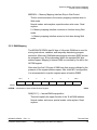
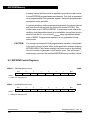
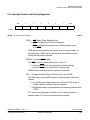
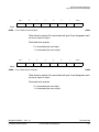
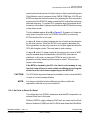
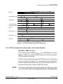
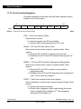
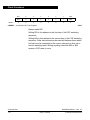
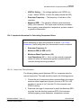
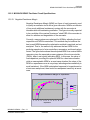
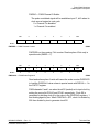
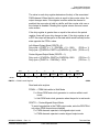
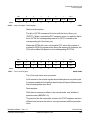
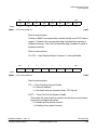
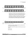
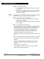
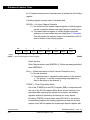
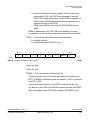
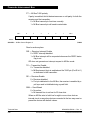
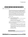
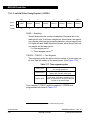
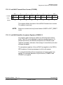
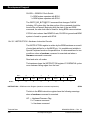
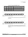
To trace program flow, setting the BKPM bit causes address comparison
of program data only. Control bits are also available that allow checking
read/write matches.
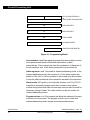
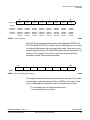
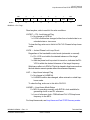
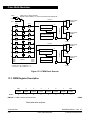
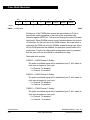
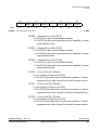
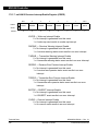
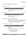
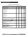
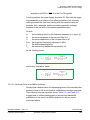
Bit 7
6
5
4
3
2
1
Bit 0
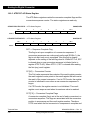
BKEN1
BKEN0
BKPM
0
BK1ALE
BK0ALE
0
0
0
0
0
0
0
0
0
0
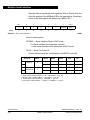
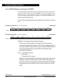
RESET:
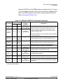
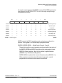
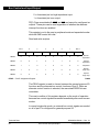
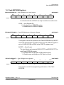
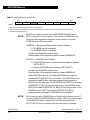
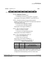
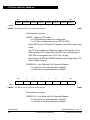
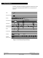
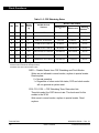
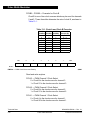
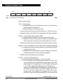
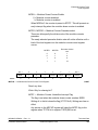
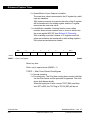
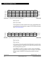
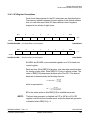
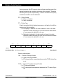
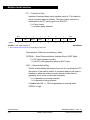
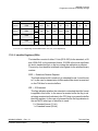
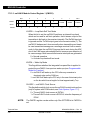
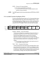
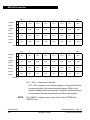
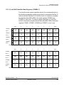
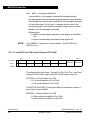
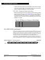
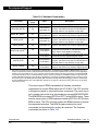
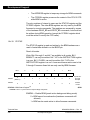
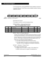
BRKCT0 — Breakpoint Control Register 0
$0020
Read and write anytime.
This register is used to control the breakpoint logic.
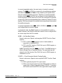
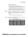
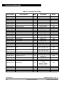
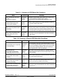
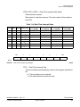
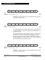
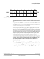
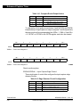
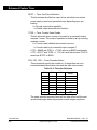
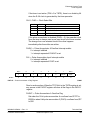
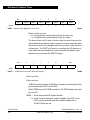
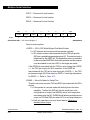
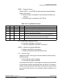
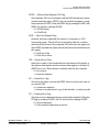
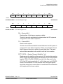
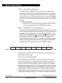
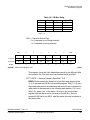
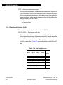
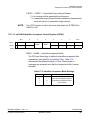
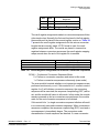
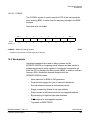
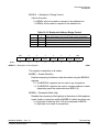
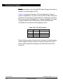
BKEN1, BKEN0 — Breakpoint Mode Enable
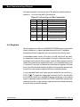
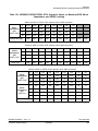
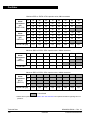
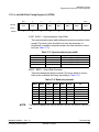
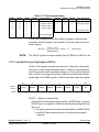
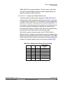
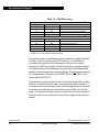
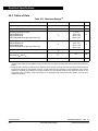
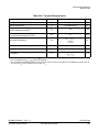
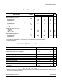
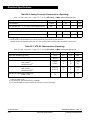
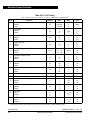
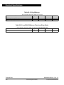
Table 19-9. Breakpoint Mode Control
BKEN1 BKEN0
Mode Selected
0
0
Breakpoints Off
0
1
SWI — Dual Address Mode
1
0
BDM — Full Breakpoint Mode
1
1
BDM — Dual Address Mode
BRKAH/L Usage BRKDH/L Usage
—
—
Address Match
Address Match
Address Match
Data Match
Address Match
Address Match
R/W
—
No
Yes
Yes
Range
—
Yes
Yes
Yes
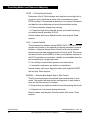
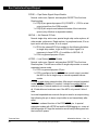
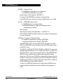
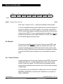
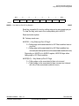
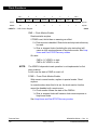
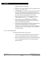
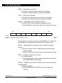
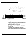
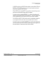
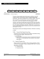
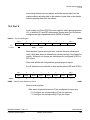
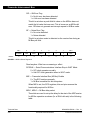
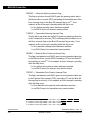
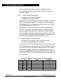
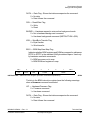
BKPM — Break on Program Addresses
This bit controls whether the breakpoint will cause a break on a match
(next instruction boundary) or on a match that will be an executable
opcode. Data and non-executed opcodes cannot cause a break if this
bit is set. This bit has no meaning in SWI dual address mode. The
SWI mode only performs program breakpoints.
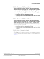
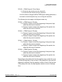
0 = On match, break at the next instruction boundary
1 = On match, break if the match is an instruction that will be
executed. This uses tagging as its breakpoint mechanism.
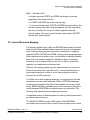
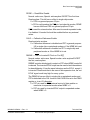
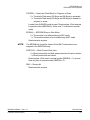
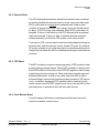
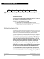
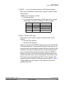
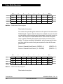
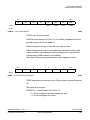
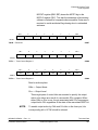
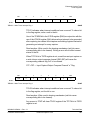
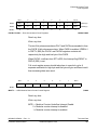
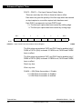
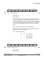
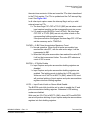
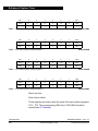
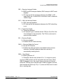
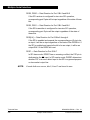
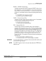
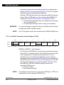
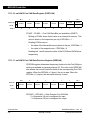
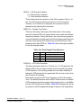
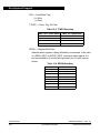
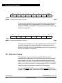
BK1ALE — Breakpoint 1 Range Control
Only valid in dual address mode.
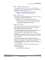
0 = BRKDL will not be used to compare to the address bus.
1 = BRKDL will be used to compare to the address bus.
Technical Data
398
MC68HC912D60A — Rev. 3.1
Development Support
Freescale Semiconductor