1
R-55TS-F
TEST PROCEDURES
PROCEDURE
LETTER
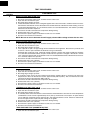
COMPONENT TEST
9. Reinstall the outer case (cabinet).
10.Reconnect the power supply cord after the outer case is installed.
11.Run the oven and check all functions.
J
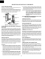
THERMISTOR TEST
1.
2.
3.
4.
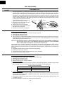
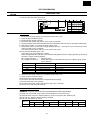
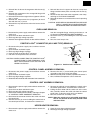
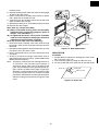
Disconnect the power supply cord, and then remove outer case.
Open the door and block it open.
Discharge high voltage capacitor.
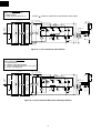
Disconnect connector-C from the control unit. Measure the resistance of the thermistor with an
ohmmeter. Connect the ohmmeter leads to Pin No’s 1 and 2.
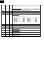
Room Temperature
68˚F(20˚C) - 86˚F(30˚C)
5.
6.
7.
8.
9.
K
Resistance
Approx. 293kΩ - 184KΩ
If the meter does not indicate above resistance, replace the thermistor
Reconnect all leads removed from components during testing.
Reinstall the outer case (cabinet).
Reconnect the power supply cord after the outer case is installed.
Run the oven and check all functions.
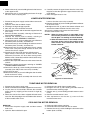
CHECKING TEMPERATURE IN THE PREHEAT OF BAKE MODE
The following test procedure should be carried out with the microwave oven is a fully assembled
condition (outer case fitted).
It is difficult to measure the exact temperature in the oven. An accurate thermocouple type temperature tester
must be used. A low priced bi-metal type thermometer is not reliable or accurate.
The temperature should be checked with outer case cabinet installed, approx. 5 minutes after preheat
temperature is reached (audible signal sounds four times). The temperature experienced may be approx.
30˚F more or less than indicated on the display, however, in most cases the food cooking results will be
satisfactory.
Difference in power supply voltage will also affect the oven temperature. The Household power supply
voltage may sometimes become lower than the rated voltage (120 V) and cause under-cooking. If the power
supply voltage is 10% lower than the rated voltage, longer cooking time is required by 10% to 20%.
L
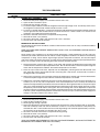
NOISE FILTER TEST
1.
2.
3.
4.
5.
6.
7.
8.
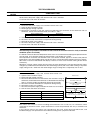
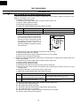
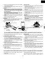
Disconnect the power supply cord, and then remove outer case.
Open the door and block it open.
Discharge high voltage capacitor.
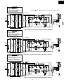
Disconnect the lead wires from the terminal the noise filter. Using an
ohmmeter, check between the terminals as described in the following
table. If incorrect reading are obtained, replace the noise filter.
Reconnect all leads removed from components during testing.
Reinstall the outer case (cabinet).
Reconnect the power supply cord after the outer case is installed.
Run the oven and check all functions.
MEASURING POINT
M
NOISE FILTER
N
L
FUSE 15A
RESISTOR 470KΩ 1/2W
LINE CROSS CAPACITOR
1.0µF / AC 250V
NOISE SUPPRESSION COIL
INDICATION OF OHMMETER
Between Hot and Neutral
Open circuit.
Between terminal N and WHITE
Short circuit.
Between terminal L and RED
Short circuit.
LINE BYPASS
CAPACITOR
0.0033µF / AC 250V
WHITE
LINE BYPASS
CAPACITOR
0.0033µF / AC 250V
RED
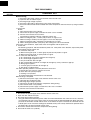
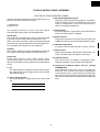
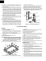
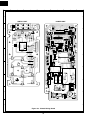
CONTROL UNIT TEST
The control unit consists of circuits including semiconductors such as LSI, ICs, etc. Therefore, unlike
conventional microwave ovens, proper maintenance cannot be performed with only a voltmeter and
ohmmeter.
In this service manual, the control unit is divided into two units, Power Unit and Switch Unit, and
troubleshooting by unit replacement is described according to the symptoms indicated.
17