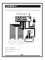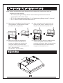
1
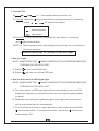
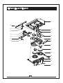
WS-38U30SS
WS-38U36SS
WS-38U42SS
WS-38U48SS
OPERATION
MANUAL
(For residential and indoor use only)
Please read and save this guide through before using your range hood.
Store the guide away in a safe place so that you will know where it is,
when you want to refer to it.
Table of Contents
A. Important Safety Instructions ---------------------------- P.1
B. Safety Notes ------------------------------------------------- P.3
C. Tools and Materials Required ----------------------------- P.4
D. Accessory Package ----------------------------------------- P.4
E. Preparing the Range Hood -------------------------------- P.5
F. Preparing the Installation Location ----------------------- P.6
G. Providing Electrical Power --------------------------------- P.7
H. Remove and Reinstall Baffle filters ---------------------- P.8
I.
Maintenance Instruction
J
Ducting
---------------------------------- P.9
------------------------------------------------------- P.9
K. Vertical Rectangular Ducting ----------------------------- P.10
L. Rear Rectangular Ducting --------------------------------- P.11
M. Mounting Range Hood to Cabinet ------------------------ P.13
N. Mounting Range Hood Without Cabinet ---------------- P.14
P. Making the Electrical Connection ------------------------- P.16
Q. Use and Care ------------------------------------------------- P.16
R. Troubleshootings -------------------------------------------- P.19
S. Replace The LED Light -------------------------------------- P.19
T. Parts Layout Diagram --------------------------------------- P.20
U. Circuit Diagram ---------------------------------------------- P.22
V. Recirculation Kit Installation ------------------------------ P.23
W. Body size ------------------------------------------------------- P.23
WARNING
Due to sharp edge, please wear " Safety Workman Gloves"
for installation, cleaning, light bulb changing and
dismantling to reduce the risk of any bodily injuries.
Safety Workman Gloves
A. Important Safety Insturctions
CAUTION- To reduce risk of fire and to properly exhaust air, make sure to properly
exhaust air. Be sure to duct air outside- Do not vent exhaust air into
spaces within walls, ceilings, attics, crawl spaces, or garages.
WARNING- To reduce the risk of fire or electric shock, do not use this fan with any
solid- state speed control device.
WARNING- TO REDUCE THE RISK OF FIRE, ELECTRIC SHOCK, OR INJURY,
TO PERSONS,OBSERVE THE FOLLOWING:
A. DO NOT spray any liquid form cleaner on hood surface including lights
and control switch. To clean the range hood, spray liquid form cleaner
directly onto cleaning cloth for hood cleaning.
B. Use this unit only in the manner intended by the manufacturer.
If you have questions, contact the manufacturer.
C. Before servicing or cleaning the unit, switch power off at service panel
to prevent power from being switched on accidentally.
D. When the service disconnecting means cannot blocked, securely
fasten prominent warning device such as a tag to service panel.
CAUTION- For general ventilating use only. Do not use to exhaust hazardous
or explosive materials and vapours.
WARNING- TO REDUCE THE RISK OF A RANGE TOP GREASE FIRE:
A- Never leave surface units unattended at high settings. Boil over cause
smoking and greasy spillovers that may ignite. Heat oils slowly on low
or medium settings.
B- Always turn hood on when cooking at high heat or when cooking flaming
foods. (ie, Craepes suzetter, charries jubilee, peppercorn beef flambe)
C- Clean ventilating fans frequently. Grease should not be allowed to
accumulate on fan or filter.
D- Use proper pan size. Always use cookware appropriate for the size of the
surface element.
1
WARNING- To reduce the risk of injury in the event of a range top grease
fire, observe the following:
A- SMOTHER FLAMES with a close- fitting lid, cookie sheet,
or metal tray, then turn off the burner. Be careful to prevent
burns. If the flames do not go out immediately, EVACUATE
AND CALL THE FIRE DEPARTMENT.
B- NEVER PICK UP A FLAMING PAN - You may be burned.
C- DO NOT USE WATER including wet dishcloths or towelsa violent steam explosion will result.
D- USE AN EXTINGUISHER ONLY IF:
1. You know you have a CLASS ABC extinguisher, and you
already know how to operate it.
2. The fire is small and contained in the area where it started.
3. The fire department is being called.
4. You can fight the fire with your back to an exit.
WARNING- Sufficient air is needed for proper combustion and
exhausting of gases through the flue (chimney) of fuel burning
equipment to prevent back drafting. Follow the heating equipment
manufacturer's guideline and safety standards such as these
published by the National Fire Protection Association (NFPA),and
the American Society for Heating. Refrigeration and Air
Conditioning Engineers (ASHRAE), and the local code authorities.
Keep the range hood clean.
WARNING- To reduce the risk of fire, use only metal duct work.
2
B. Safety Notes
1. All electrical work must be done in accordance with local and/or national
electrical code as applicable for safety. This product must be grounded
if your are unfamiliar with methods of installing electrical wiring, secure
the services of a qualified electrician.
2. Turn off power at service entrance before installing wiring or servicing
this product. (120 volt for range hood. 220 volt for electric range if any)
3. Turn off power to avoid risk of fire, electric shock, or injury for cleaning
or maintenance such as lubrication.
4. Fireplaces, gas furnaces, water heaters, require proper flow of
combustion air and exhaust. Make sure this flow is not altered when
using any exhaust fan.
5. Please read specification label on product for further information and
requirements.
6. Please wear "Safety Gloves" for installation, cleaning, light bulb
changing and dismantling to reduce the risk of any injuries.
CAUTION- To reduce the risk of fire and to properly exhaust air, be
sure to duct air outside. Do not vent exhaust air into spaces
within walls or ceilings or into attics crawl spaces or garages.
3
C. Tools and Materials Required
Drill, electric of ratchet driver, with 3/16" wood bit (for drilling starter
holes and 1 ¼ ” wood bit (to drill an access holes in the cabinet or
kitchen wall for the electric power line)
One common screwdriver.
Plier (for opening electrical knockout).
Two 1" (thick)x2" (wide)x12" (approximate length) wood strips for
recessed bottom kitchen cabinet installation only. (Purchase locally).
Electrical wire and supplies to comply with local cords.
Four 1 ¼ ” long flat head wood screws (purchase locally) to mount
wood strips.
Pencil and ruler for marking locations. Saber saw or keyhole saw for
cutting the 1"x2" wood strips to length.
D. Accessory Package
1. Wood screws 3/16" x 1" L
6pcs.
2. Wire connector with spring 3pcs.
3. Washer
6pcs.
4. 6”/7” Vertical starting round collar 1pc.
4
E. Preparing The Range Hood
1. Remove the top electrical
Electrical Knockout
knockout, you may plan to
bring power to the range
hood either through the
cabinet or through the wall
(Fig.1)
Fig.1
2. Insert a screwdriver into the knockout slot and bend the knockout
back and forth. (Fig.2)
3. You may have to use pliers to pull the loosened knockout free.(Fig.3)
Fig.3
Fig.2
28”-32”
4. When installed, the bottom edge
of your range hood should be
28" ~ 32" above the top of the
cooking surface. (Fig.4)
Fig.4
5
F. Preparing The Installation Location
1. If you want to move the electric range to make room for working on the cabinet
turn off the 220 volt power for the electric range at the service entrance.
2. Before moving a gas range, shut off the gas.
NOTE: SKIP FOLLOWING STEPS 3A THROUGH 3D IF THE HOOD IS TO BE
MOUNTED ON A CABINET WITH A FLUSH BOTTOM .
3. For installation onto a recessed bottom cabinet:
a. Measure the space (under the cabinet between the inside front edge and
inside back edge (Fig.5). With a saber saw, cut two 1"x2" wood filler strips
(purchased locally) to fill in the bottom of the cabinet.
b. Start a 1 ¼ " long wood screw (purchased locally) about 3" from each end
of the 1"x2" wood strips (Fig.6)
c. Position the strips on the cabinet bottom and screw the strips securely to
the cabinet (Fig.7)
d. For a more secure installation, drill four 3/16" holes from inside the cabinet,
down into the wood filler strips. Insert screws into the starter holes in
cabinet and tighten screws until wood filler strips are secured under cabinet.
4. Center the hood in place beneath the cabinet and flush with the front of the
cabinet. Mark the following:
a. The six keyhole mounting slots for the hood. Mark these onto the bottom of
the cabinet; or, if the cabinet bottom is recessed. Onto the wood strips (Fig.7)
b. The electrical knockout hole. (Fig.1)
Fig.6
Fig.5
6
C. Screw the four 1" wood screws (for
mounting the hood) into the exact
center of the arrow and into the keyhole
mounting slots marked on the cabinet
bottom (for flush installations), or
marked on the 1” x2” wood strips (for
Strips secured
recessed cabinet installation) (Fig.7)
Do not turn the mounting screws in all
Fig.7
the way. Allow 3/8" of screw to project,
so the hood can be fitted place.
(The screws will be tightened later)
G. Providing Electrical Power
1. After turning off the proper 120 volt circuit at the service entrance,
drill out the electrical power line access hole marked on the cabinet
bottom or wall. Use a 1 ¼ ”wood bit. (Fig. 8)
2. Fish the electrical power line through the access hole drilled in the wall or
bottom of the cabinet. Attach an appropriate connector (purchased locally)
to the end of the power line for the type of wiring being installed. Follow all
codes. (Fig.9)
Safety Warning:
If drilling into the walls, be careful not to cut existing electrical cables,
which would create a hazard.
Color:
green/white/black
1
" bit
Connecter
Fig.8
Fig.9
7
H. Remove and Reinstall Baffle filters
②
①
1. Wear safety workman gloves and
2. Push Baffle filter down ward ①,
hold the handles of Baffle filter.
then pull a little back ②.
③
4. Pick up the inner oil collector.
3. Lift up the Baffle filter ③.
NOTE : Reinstalling Baffle filters. Reverse the steps as removing Baffle filters.
For mounting under cabinet
1. After above step H, then continue the following steps.
2. Remove 2 screws on the spacer(s).
3. Remove spacer(s).
4. Key hole to mount to under cabinet.
!
!
Key hole
8
I. Maintenance Instruction
1. Maintenance shall be important than repair. Please take care of the
needed maintenance in order to secure and extend the excellent
functions and using life.
Note : Before repairing the range hood. Disconnect the power source.
2. After using the machine, wipes the machine by neutral detergent in
order to keep it clean and maintain the appearance with brightness
and sanitation.
3. When the level of dirty oil of the collector reached 4/5 of height, it has to
be removed in order to avoid overflowing and pollution.
J. Ducting
This style of range must be vented via ducting to the outside of the house.
Follow general rules when ducting the hood: Use correct size of ducting
(6" or 7” round ), do not reduce size of ducting, make all turns gradual,
no short corners. If ducting ran will be longer than 10 feet enlarge duct by
at least 1" inch diameter after each 10 feet. Tape all joints in ducting and
all gasketed openings on hood for a tight seal.
For round ducting from the top:
Loosen 2 screws (Ref.1), fit the gray plastic round collar / 6” over the circular
opening on top (Ref.2) and fasten 2 screws (included) in order to provide a tight
seal for ducting to attach to (Ref.3), if you want to use 7” ducting, take 7” converter
(included) to join together with the 6” round collar(Ref.4).
1
2
!
3
!
!
Fasten
Loosen
Loosen 2 screws
4
F asten 2 screws
Fit 6" collar
9
Fit 7” converter
K. Vertical Rectangular Ducting
A. Remove the pre-mounted
D. Overlap the rectangular
starting collar on the top
6” round duct opening.
of transition plate.
Half round section
E. Mounting rectangular starting
collar with remaining screws.
B. Put transition plate by first
installing 4 screws on the
half round section.
(Optional)
F. Completely finished .
NOTE :
An optional kit for vertical
rectangular ducting :
Transition plate
C. Take the rectangular starting
+
Rectangular
starting collar
collar. (Optional)
(Small)
10
L. Rear Rectangular Ducting
A. Remove the pre-mounted
D. Pre-mounted
6” round duct opening.
rectangular plate.
B. Put transition plate by first
installing 4 screws on
E. Remove the pre-mounted
the half round section.
rectangular plate.
(Optional)
- to be continued -
C. Use slotted screw driver,
(or whatever flat head)
to knock out the pre-mounted
rear rectangular cap.
11
L. Rear Rectangular Ducting
!
F. Take the pre-mounted
G. Mount the rectangular
rectangular plate.
plate (previous removed)
!
on top of transition plate.
NOTE :
An optional kit for rear
rectangular ducting :
Transition plate
+
Rectangular
starting collar
H. Insert appropriate rectangular
starting collar (optional)
(Small)
or
(2 different size)
ⓐ 11 ¼ " x 3 ¾ " x 1" (L x W x H)
(Large)
ⓑ 11¼” x 3¾” x 3⅛" (L x W x H)
! or
(Small)
I. Mount rectangular
(Large)
J. Rectangular starting collar.
starting collar.
( 11¼” x 3¾” x 3⅛" L x W x H )
( 11 ¼ " x 3 ¾ " x 1" )
(optional)
(optional)
12
M. Mounting Range Hood To Cabinet
NOTE : Read “Remove and Reinstall Baffle filter” & “For mounting under cabinet”
on page 8.
1. Position the hood in place so that :
a. The electrical line is routed through the appropriate Knockout
opening. This step will have to be accomplished while positioning
the hood (Fig.10)
b. The large part of the keyhole mounting slots on the hood fit onto
the hood mounting screws projecting from the bottom of the
cabinet. (Fig.11)
2. Adjust the hood so the front is flush with the cabinet front.
3. Tighten the hood mounting screws all the way into the cabinet or into
the 1" x 2" wood strips so the hood is secure.
Color:
green/white/black
Fig.11
Knockout opening
Fig.10
Fig.11
13
N. Mounting Range Hood Without Cabinet
Bracket
1. Using metal brackets and screws
(included), center hood onto
Screw
board and install screw.
2. Remove the hood from the board and
nail the wood board onto the wall.
(Be sure the nail is in the center of
the stud)
3. Place the range hood on the board
and tighten the screw.
4. Completely finished
14
Mounting range hood without cabinet
Chimney Installation Chart (optional)
1
2
"
"
"
oor
1. Set 6” round ducting
collar or
2. Set rectangular starting
collar (check manual)
Check and fix the
ower chimney
bracket
7” round converter collar
(for 7” exhaust piping)
"
Install the range hood
to the desired position
3-2
3-1
4
6
5
?
"
>
Slide the chimney
(upper + lower)
into the base
"
Note:
"
Install the 6” piping tube or
7” piping tube (Ref fig 3-2
use converter), or rectangular
piping exhaust outlet.
Note: all piping tubes are not
included.
Tape all joints in ducting and all gasketed opening on hood for a tight seal.
7
8
Check 2 screw holes
Note:
10
9
"
9
Check the desired length of
chimney and mark the position
for upper chimney bracket then
fixed. each section 19-1/2” (50cm)
in length maxi extention length
38” (96.5cm)
"
Fasten 2 screws
"
Extend the upper chimney Check 2 screw holes
up to the desired position and fastened
(complete finished)
1.Duct cover and extension duct cover fitment may vary depend on the mounting height of
the range hood.
2.Make sure you can easily peel the white protection pvc film after installation, otherwise
please peel it before chimney installation.
15
P. Making The Electrical Connection
1. Remove stainless Baffle filters. ( Ref.P8-H)
2. Remove screws on wiring case,
wire case
fish out wires through the
knockout. (Fig.12)
3. Mark the electrical connection by
fastening all wires to the existing
wall wiring according to the their
colors. (Black to Black, White to
White, Green to Ground)
Fig.12
4. After connection is done, reinstall wiring case cover and bottom board.
5. Turn on power and check operation of fan and light.
6. After completely installation, reinstall the stainless Baffle filter and oil collector.
( Ref. P8-H)
Q. Use and Care
Night light sensor
OFF
Main power
1.
3 speed fan selection
Fan OFF
LED light
Main power button
NOTE: ALL FUNCTIONS CAN BE WORKED ONLY UNDER THE
MAIN POWER IS ON.
A. By pressing
, all functions are stand-by.
B. By pressing
again, all functions will be turned off.
16
2. Use for Fan
OFF
A. Fan ON : When the
button
: Fan speed selection and fan off.
main power button is being pressed, by pressing
/
/
for desired fan speed.
- slow speed
- medium speed
- high speed
B. Fan OFF : To turn off the fan, just press the
the
OFF
button, or press off
main power button.
NOTE: a. The fan speed can be interchanged by pressing any one of above
3 buttons, however.
b. NEVER PRESS ANY OF TWO BUTTONS IN A TIME.
3. Use for Light
NOTE: MAKE SURE THE
MAIN POWER BUTTON IS PRESSED BEFORE
TURNING ON THE LED LIGHT.
A. Press
to turn on the LED light.
B. Press
again tor turn off the LED light.
4. Use for Auto-sensor LED night light
NOTE: MAKE SURE THE
MAIN POWER BUTTON IS PRESSED BEFORE
TURNING ON THE LED LIGHT.
A. The auto-sensor of LED night light will be automatically turn on at 20%
brightness compare to original when the surroundings is getting darker
(or dark).
B. When the surroundings is getting brighter (or bright), the auto-sensor
will turn the night light off automatically.
C. To turn off the auto-sensor night light button, after cooking turns off the
main power button. To keep this function, remain the
button always ON.
17
main power
Note:
Range hood should be turn on either before or the same time when cooking
begins. After cooking, range hood should be kept on for about 3 more minutes
for complete ventilation of cooking odor.
Care Instruction :
Please always pull the plug out before cleaning or dismantling, wear
" Safety gloves " to reduce the risk of any injuries.
Exterior : Can be cleaned with any type of non-abrasive detergent and a
clean cloth. " Green Pad " or any metal type cleaning pad is
not recommended for exterior. As those may scratch the
graphic wordings on control panel.
Interior : 1. Switch ON the fan at High, mix mild detergent with water in
mist-sprayer, at fine-spray mixture on to the blades for 60 seconds
with the fan running. ( mist sprayer is not included)
2. Leave fan on for an additional 3 minutes to dry oil basin.
3. Repeat on other turbine vane (can be cleaned simultaneously
with the first).
18
R. Troubleshootings
Symptom
Correction
A. Check power source to see if it is normal.
Fan are not operatable.
Illuminating LED light
does not work
B. Check power inlet plug to see if it is
plugged firmly into it's socket.
A. Disconnect the power source.
B. Check LED light, replace it with a new
one if it is burned out.
A. Check for damaged vanes.
Hood vibrates.
B. Check if exhaust duct is secured.
S. Replace The LED Light
Before changing LED light ensure the unit is pressed the
main power button off,
when you want to change the LED light please always wear working gloves.
1. Using suitable tool (small slotted screw driver) gently pry off the LED light set.
2. Taking off the wire connecter with LED light set.
3. Replace a new LED light set and reconnect the wire to the connector.
4. Before push back the original LED light position, test the LED light.
LED driver:
Model: HP1500-36
input: 100~240vdc
output: 3.6vdc=1500maH
LED light: 1W
Model: HP-15A
NOTE: For LED light replacement, you may not find the appropriate LED lights
from market, please contact with distributor(s)/dealer(s).
19
T. Parts Layout Diagram
1
20
19
4
18
5
17
3
16
15
2
14
6
7
8
9
10
11
12
13
20
Parts List
No.
Description
Parts no.
Per hood
1
Hood casing
38-0130(30”) / 38-0136(36”)
38-0142(42”) / 38-0148(48”)
1
2
Air chamber
38-02
1
3
Top plate
38-0330(30”) / 38-0336(36”)
38-0342(42”) / 38-0348(48”)
1
4
6” round vent ( Vertical ventilation )
38-04
1
5
Motor housing
38-05
2
6
Inner vent (Rear ventilation)
38-06
1
7
Motor (s)
38-07
2
8
Fan (s)
38-08
2
9
Oil tunnel
38-09
2
38-1030(30”) / 38-1036(36”)
38-1042(42”) / 38-1048(48”)
2
10
* Spacer (s)
11
* Baffle filter (s)
38-11
2
12
* Handle (s)
38-12
4
13
Oil collector
38-13
2
14
* LED light
38-14
2
15
LED light fixture
38-1530(30”) / 38-1536(36”)
38-1542(42”) / 38-1548(48”)
1
16
Control panel
38-16
1
17
Control button
38-17
1
18
LED driver
38-19
1
19
Bracket
38-20
2
20
Wiring partition
38-2130(30”) / 38-2136(36”)
38-2142(42”) / 38-2148(48”)
1
■ With * (asterisk) on 42” / 48” quantity may be varied.
21
U. Circuit Diagram
NOTE : Any faults with this unit should only be attended to by a qualified technician.
NIGHT LIGHT
H I
OFF
POWER
CORD
W
Y
W
Y
J K
LED
LED
K
J
WHITE
RED
YELLOW
GRAY
BROWN
BLUE
WHITE
RED
YELLOW
BLUE
GRAY
BROWN
H
I
AC/DC
POWER SUPPLY UNIT
MOTOR
MOTOR
Voltage : 110V/60Hz
Power consumption : maxi 170W
(Motor + LED light)
22
V. Recirculation Kit Installation (optional)
Note: Before mounting the range hood and recirculation kit, please must refer the
following from the manual.
1. P.5 “E. Preparing the Range Hood” remove the top electrical knockout
(recirculation kit is same step)
2. P.7” G. Providing electrical power” , P.13”M. Mounting Range Hood To Cabinet”.
3. P.8 “H. Remove and Reinstall Baffle filters”.
(1). Mount the recirculation kit to the bottom
of the cabinet. (Use the wood screws
provided with range hood)
(1)
(2)
(2). After securing the recirclation kit to the
bottom of the cabinet, make sure to run
the path for the electrical power cord.
(3)
(3). Before mounting the range hood,
be sure to connect the electrical
power cord. Mount the range hood
using the screws porvided to the
bottom (4 sides)of the recirculation kit.
(30” - 5 pcs screws)
(36”/42”/48” - 9 pcs screws)
(4)
(4). Before powering the unit, make sure all
screws and power cord have been
properly connected. After all connections
have been secured your recirculating
range hood is ready for use.
W. Body Size
”
11
8-3/8”
5”
22
2°
-7/
16
3
”
23
3
0”(
6”)
”)
(42
(48
”)
Limited Warranty
Windster Hoods Inc. warrants this product against defects in material or
workmanship as follows:
1) Labor: For a period of one (1) year from the date of purchase, if this product
is determined to be defective, Windster will repair or replace the product, at its
option, at no charge. After the warranty period, you must pay for all labor
charges. During the “labor” warranty period there will be no charge for labor.
2) Parts: In addition, Windster will supply, at no charge, new or rebuilt
replacements in exchange for defective parts for a period of two (2) years.
After the warranty period, you must pay for all parts costs. During the “parts”
warranty period, there will be no charge for parts
You must carry-in or mail-in your product during the warranty period. This warranty
only applies to products purchased and serviced in the United States or Canada.
What Is Not Covered By These Warranties:
1) Conditions and damages resulting from any of the following:
?
Improper installation, delivery, or maintenance.
?
Any repair, modification, alteration or adjustment not authorized by the
manufacturer or an authorized service dealers.
?
Misuse, abuse, accidents, or unreasonable use.
?
Incorrect electric current, voltage or supply.
?
Improper setting of any control.
?
Improper chemical cleaning.
2) Light Bulbs
3) Products purchased for commercial or industrial use (such as in a hotel, office,
restaurant, or other business)
4) Damage due to earthquake, flood, storm, etc.
Defective Products:
All products will be inspected, tested, and carefully packed by the manufacturer
before shipping to customers. Products that are damaged during transit can only be
exchanged for the same product, under the condition that the customer must get a
RMA (Return Merchandise Authorization) from Windster. When products are
received defective, you must notify us within the 3 business days of receiving the
package. Replacement products are only shipped when the RMA is issued. NO
EXCEPTIONS.
Return Policy
Windster offers only the best and highest quality products. If you are not satisfied
with your purchase, please contact us within 3 business days of product arrival to
obtain a Return Merchandise Authorization (RMA). Returns sent without a RMA will
not be accepted. There will be a 25% re-stocking fee for every returned items.
Shipping fee will also be deducted from the original purchase price. When returning a
package, please include a copy of your purchase receipt. Use the original shipping
box and packing materials and completely remove or cover the original shipping label.
Make sure that products are in brand new condition, uninstalled, un-drilled, and
contain everything that came with the package as when you first received it. If any
parts or manuals are missing, we have the right not to accept the return.
We suggest that you use a traceable and reputable carrier of your choice to ship your
return. Your credit or refund will be processed within 10-14 business days from the
date we receive your return.
5101 Commerce Dr. Baldwin Park, CA 91706 TOLL FREE:1-877-350-5215
FAX:626-962-8669
Website: www.windsterhood.com Email: [email protected]
WINDSTER
TM
www.windsterhood.com
5101 Commerce Dr
Baldwin Park, CA 91706
TOLL FREE:1-877-350-5215
FAX:(626)962-8669
© Windster Hoods, Inc.
Specifications subject to change without notice.