1
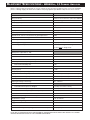
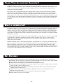
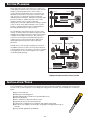
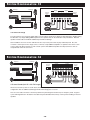
M PA M U LT I - C H A N N E L P O W E R A M P L I F I E R
2
4/
OW
LP
NE
AN
CH
ER
AM
PL
IFI
ER
MP
A6
14
4X
80u
s
0W
34
2X
0/
•
RS
2
KE
EA
HM
O
SP
H4
+
–C
AB
ST
3+
LE
RS +
2
KE
EA – CH
SE
2V
FU
H
–C
SP
1+
H
–C
+1
MPA 680us
4/2 Channel Mobile Audio Amplifier with 680 Watts Max. Power
Amplificateur audio mobile de 680 watts de puissance maximum à 4/2 canaux
Amplificador Móvil de Áudio de 4/2 Canales con Potencia Máx. de 680 vatios
Amplificador Móvel de Áudio de 4/2 Canais com Potência Máx. de 680 Watts
BLAUPUNKT SPECIFICATIONS -
MPA680US, 3/2 CHANNEL AMPLIFIER
Below is a basic trouble-shooting guide to assist in seeking out and correcting a problem that may occur in the installation
process. Although lengthy, this chart cannot address every single problem possible but mainly the ones most common.
PARAMETER/FEATURE
VALUE
Channels
4/2 active channels
Size ( W x H x D)
8.69 x 2.19 x 15.75 inches (220 x 56 x 400mm)
Weight
8.6 lbs (3.9 kg)
Crimping style speaker terminals?
YES
Maximum terminal wire size
8 ga.
Subsonic filter
YES (10Hz)
Separate front/rear or left/right gains?
YES (sep. front/rear in 4ch/sep. left/right in 2 ch.)
Spade type auto fuses?
YES
Speaker short, short to +12V, and short to ground protection?
YES
High, low, and reverse voltage protection?
YES
Power output transistors
High current, bipolar outputs
Switching power supply transistors
High-Speed, MOSFET’s
Minimum speaker impedance
2 ohms (non-bridged mode only)
4 ohms ONLY in bridge mode
PERFORMANCE DATA
VALUE
Rated power output @ 0.1% THD
2 channels into 4 ohms / 2 ohms
4 x 55 W / 4 x 100 W
1 channel into 4 ohms
2 x 150 W
Total Harmonic Distortion @ rated full output
0.06% THD
Rated Signal/Noise ratio (averaged value)
> 90 dBA
Measured @ full rated power
102
Measured @ 1 watt / 1 kHz
87
Damping factor
>100
Frequency response (full-range mode)
20 - 50,000 Hz
High-pass crossover frequency limits
50 - 500 Hz (continuously variable control)
Low-pass crossover frequency limits
50 - 250 Hz (continuously variable control)
Input impedance
20 kOhms
Input signal voltage control range
0.3 - 4.0 Vrms
Current draw for undistorted output @ 14.4 VDC
@ full undistorted output, non-bridged
32.5 A (4 ch x 55 W x 4 ohms)
@ full undistorted output, bridged mode
48.0 A (2 ch x 150 W x 4 ohms)
@ 33% of undistorted power (full “music” power)
18.0 A (4 ch x 18 W x 4 ohms)
@ idle
1.0 A
Minimum battery voltage to maintain rated power
12.6 Volts DC
Usable battery voltage
10 - 18 Volts DC
Trigger line voltage range
10 - 18 Volts DC
Trigger line current draw
< 15 mA draw
Turn on delay time
@ 1.5 seconds
Thermal shutoff temperature (averaged heat-sink exterior temperature)
170°F (80° C)
NOTE: DUE TO ONGOING PRODUCT IMPROVEMENTS, DESIGN AND SPECIFICATIONS ARE SUBJECT TO CHANGE
WITHOUT ADVANCED NOTICE TO THE CONSUMER OR RETAILER.
THANK YOU
FOR CHOOSING
BLAUPUNKT!
Congratulations! You are the now the owner of an exceptional car audio amplifier from the audio enthusiasts at
Blaupunkt. Our engineering staff has spent considerable time refining our MPA series amplifiers in order to introduce great
sound to the consumer at an affordable price. With these products we focus on sonic performance but balanced with
rugged design and flexible installation.
Not only do we offer you a great product but also a supportive owners manual. This manual can be used as a teaching
guide due to its brief, but informative, explanations of amplifier and system design. We are also very concerned about the
end consumer using proper installation techniques for the highest performance possible from their new audio products.
MOST important to us are the concerns with safety and the installation process. Since our Blaupunkt retail dealers have the
tools and experience for an optimized and safe installation, we always recommend they do the final vehicle integration. But,
should you choose to install these products yourself, please take the time to read this manual completely and abide by all
precautions.
WHAT
IS AN
AMPLIFIER?
An amplifier, by definition, is a device that receives a small audio signal on its input and reproduces it with larger voltages (or
current) on its output. Ideally there should be no modifications of the signal other than to make the signal larger either in
voltage or current levels. If there are changes in the signal character it is considered a "distortion" of the input signal and in
most cases undesirable. With the added power of an amplifier you can play your system at higher volume levels without
worrying about such distortions that actually can damage the speakers and your ears (assuming of course that the amplifier
is NOT grossly over-driven).
The perfect amplifier will be able to reproduce any output voltage regardless of input signal level. But, infinite output voltage
is impossible due to upper limits created by the voltages found in a car, typically 12-15 volts DC. In order to achieve
undistorted power levels beyond about 20 watts per channel a switching power supply MUST be used to step up the
voltage "rails" inside an amplifier.
Amplifiers are rated in "watts" of audio output power but there are often references to "rms" power and "MAX" power. Rms
power is considered as "clean power" since it is undistorted power that is used for reproducing quality sound at all but the
highest listening levels. "MAX" power is the most power the amp will produce when driven deep into distortion. MAX
power is considered usable power only by the more "aggressive" listener since the original waveform is so distorted that it is
uncomfortable to listen to for most people. Regardless of the consumer's listening habits, we dual list these power levels so
everyone has an understanding of what they are purchasing.
KEY FEATURES
Your new Blaupunkt MPA series amplifier, although a simple product, offers some important features. These include:
■ "Multi-Mode" operation allowing for combined stereo high-pass/bridged mono subwoofer low-pass output capability.
■ 2 ohm stability (in non-bridged mode) for paralleling two, 4 ohm speakers.
■ RCA inputs (low level) allowing for your typical aftermarket radio signal level outputs.
■ Modular inputs (high level) for tapping off of the speaker outputs of a factory radio for example to derive a subwoofer
signal for an add-on subwoofer speaker system.
■ Internal low pass filters for easily deriving a subwoofer system without an add-on crossover that increases system
complexity and the potential for noise.
■ Variable frequency low-pass and high-pass filters (on upper MPA models) for custom tailoring the crossover
frequency choice for any vehicle.
■ Efficient heat-sink design to quickly wick away heat thus ensuring a life time of reliability.
■ Simple mounting system for ease of installation.
–3 –
SAFETY CONCERNS
We always recommend you have your Blaupunkt amplifiers professionally installed but the
installation process is often so easy that the average consumer can achieve success with little
trouble. Regardless of the person installing, you should be sure to review the following points
before proceeding with the installation:
■
READ THE MANUAL! Understanding the product and installation limitations before
■
WEAR SAFETY GLASSES AT ALL TIMES - Flying debris are always dangerous.
PROTECT THE VEHICLE - Always disconnect the negative battery cable before
lifting a screwdriver.
■
■
■
■
starting any kind of installation work. This prevents a possible high current electrical
short (potential fires).
HEAT - Keep all audio components away from nearby hot vehicle components that heat up over time such as hoses,
high current wires, and braking system components.
GIVE YOURSELF LOTS OF TIME - Rushing to complete an installation nearly always ends up with problems.
DO NOT LISTEN AT HIGH SOUND LEVELS FOR A PROLONGED TIME - these amplifiers, used with high
efficiency speakers from ANY manufacturer, have the potential to cause permanent hearing loss after listening at
maximum volume levels for several hours.
INSTALLATION WARNINGS!
Before disassembling your beautiful new car you need some basic installation knowledge and skill with common hand and
power tools. Following such basic installation tips and warnings will prevent possible damage to the vehicle and also
prevent possible fires.
■
■
■
■
■
■
■
■
■
■
AGAIN...READ THE MANUAL! There is a lot of helpful information in this manual that
will save time and prevent problems later.
COVER THE VEHICLE WORK AREAS - Use fender covers or blankets to protect the
work areas from scratches or dings.
DISCONNECT THE (-) LEAD ON THE BATTERY - No sparks or fires please!
“REVIEW” THE INSTALLATION - Before using any tools or moving vehicle
components, take five minutes to review the installation intentions (e.g., verify that an
amplifier will fit in an area of a car before tearing out all the interior).
“REVIEW” THE VEHICLE - Before drilling any holes or cutting into any surfaces, make
sure there are no fuel or hydraulic lines behind the surfaces. Also make sure there are no
wires routed directly behind or near the desired mounting area (remember...screws can
often extend 1-2 inches behind the mounting surface).
ENSURE PROPER FIT - Before cutting or drilling, make sure the amplifier will physically
fit in its desired location. Check for clearance around rear deck torsion bars or other
structural elements.
EVERY CAR IS ASSEMBLED DIFFERENT - Every auto manufacturer uses different
assembly techniques. Take care in removing/modifying all trim panels and mounting surfaces since they often use
unique screws or snap fasteners that are difficult to replace if they are lost or broken.
BE CAREFUL WITH CABLE ROUTING - When routing audio cables, make sure RCA and speaker wires are
routed away from high current power lines for audio amplifiers and vehicle systems lines when possible. This will
help prevent noises from creeping into the audio system, plus prevent potential damage to the vehicle wiring itself.
BE CAREFUL WITH ALL CONNECTIONS - When making connections, make sure each connection is clean
and properly secured. Observe all polarity markings carefully to ensure proper end performance.
CAUTION - FUEL TANKS AND FUEL LINES ARE NOW LOCATED DIRECTLY BENEATH THE REAR
DECK IN MANY CARS - CHECK FOR ADEQUATE CLEARANCE BEFORE EVEN CONSIDERING
SUCH A MOUNTING LOCATION!
–4 –
SYSTEM PLANNING
Before wiring up an audio system that may not achieve the
sound quality you want, be sure to choose a system concept
that fits your listening requirements. Basic systems, a
receiver with internal 4x20 watts and 4 coax speakers, are
adequate for many listeners. But, when you want to really
“feel” the music, you will need some kind of subwoofer
amplifier/speaker combination. Although many people might
jump into an “add-on” amplifier to power to rear coaxial
speakers, a better choice is usually a subwoofer
amp/speaker system that supplements the existing 4 speaker
system as shown in the adjacent drawing. Such a system
provides a surprising improvement in sound quality due to
the usually dramatic increase in bass response.
The next dramatic step up in performance is with a “multichannel” system that offers more dynamic range in the mids
and highs due to higher power plus more bass response due
to multiple woofers and/or more power. But, with such a
system, the stereo image and overall listening experience
usually becomes much more life-like due to better tonal
quality midrange/tweeter speakers and usually better
placement.
Full-Range
Full-Range
Subwoofer
Full-Range
Full-Range
Supplementary subwoofer system
Tuner
Passive X-over
Sat Amplifier (4x50 W)
To build such a system though, complexity goes up due to
the addition of passive or active crossovers which take time
to install and may inject noise into the system due to potential
noise signal pick up. The results though of such a system
can be dramatically pleasing.
Sub Amplifier (2x100 W)
Subwoofers
High performance multi-channel system
INSTALLATION TOOLS
For most installations, simple hand tools are adequate to install an aftermarket amplifier. Depending upon the mounting
locations used, you will need power tools for drilling and cutting plastics and metal. A good starting list is summarized
below:
■
■
■
■
■
■
■
■
■
Tape measure and ruler
Marking pen and starting punch
Phillips and flat blade screwdrivers (small and medium sizes)
Nylon wire bundle ties
Pliers: standard vice-grip and needle nose styles
Light-duty trim pry-bar for removing door trim
Cutting shears or nibbling tool for cutting thin and medium gauger metal
Wire cutters, wire strippers, electrical tape, crimping pliers and appropriate crimp-on
terminals
Power drill with appropriate sized drill bits
–5 –
VEHICLE WIRING
VEHICLE FUSING
For safety purposes, a high current fuse (or circuit breaker)
MUST be installed in line with the amplifiers(s) immediately at
the battery to prevent vehicle damage should the battery line
in advertently shorted to the vehicle chassis. The chart at the
right shows the recommended master fuse sizes for an
average audio system with noted “rms” output power levels.
POWER WIRING
Most vehicles built since 1990 have adequate current
capability for your amplifier. Except for systems above about
500 W rms, the factory charging system and battery should
easily support it if properly installed. Proper wire size must
be chosen to ensure adequate current delivery to the amp.
Wire size (gauge) of the cables need to increase in size for
higher power systems. (Wire sizes larger than those noted
are usually a waste of time and money since they offer Little
or no performance improvements.)
Wire diameter must increase (decreased wire gauge number)
for higher power systems. For long wire runs the wire
diameter must also increase. The wire sizes noted allow for a
maximum 0.5 volts DC drop over the give wire run which
results in Sound Pressure Level drops inaudible to the
average listener.
SPEAKER WIRING
As with power wire, speaker wire size (gauge) changes with
the power required and the length of the wire run. The
speaker wire chart shows the minimum recommended wire
size for a single audio output channel driving a loudspeaker
at a given distance with a maximum power loss of 0.5 dB,
the threshold of audibility. (Wire sizes larger than those noted
are usually a waste of time and money since they offer little or
no performance improvements.)
SYSTEM FUSE CHART
(Fuse size for total amplifier system power in “rms” watts)
Fuse Size
(in amps)
100 W
200 W
500 W
1000 W
20 A
30 A
50 A
100 A
SYSTEM POWER AND GROUND WIRE CHART
(Wire gauge for total system in 'rms' watts)
WIRE LENGTH
100 W
200 W
500 W
1000 W
5 ft. / 1.5 m
12
10
8
4
10 ft. / 3.0 m
12
10
8
4
15 ft. / 4.5 m
10
8
6
2
20 ft. / 6.0 m
10
8
6
2
25 ft. / 7.5 m
10
8
4
0 or 00
LOUDSPEAKER WIRE CHART
(Wire gauge per loudspeaker/speaker power in “rms” watts)
WIRE LENGTH
20 W
50 W
100 W
200 W
5 ft. / 1.5 m
18
16
16
16
10 ft. / 3.0 m
18
16
16
16
15 ft. / 4.5 m
16
16
16
14
20 ft. / 6.0 m
16
16
16
14
25 ft. / 7.5 m
16
16
14
12
FINAL VEHICLE WIRING
Current requirements for an upgraded audio system dictate a
dedicated power line be run from the amplifier directly to the
battery of the vehicle. This line should NOT be run to the
fuse panel of the vehicle but directly to the battery. DO NOT
run to the alternator either. There MUST be a fuse installed at
the battery with adequate amperage as shown in the chart
above.
Battery
Battery
Connector
Fuse or
Circuit
Breaker
Radio
As for the final signal wiring, be sure to route the audio cables
down the side of the car opposite the power lines to avoid
noise pick up from the lines. Also, try to route all audio
cables away from noise sources such as engine computers
and ABS brake computers.
Power Antenna
Turn-On Wire
(18-20 gage wire)
Speaker Wires
or
RCA Cables
Proper power grounding is important to insure adequate
current flow. Be sure to grind the surface clean of all paint to
ensure a solid electrical connection.
Speakers
Amplifier
Ground Screw
Drill 1/8” hole in
chassis sheet metal
Use the same ground if
using multiple amplifiers
–6 –
Grommet
To prevent
damage to
power wire
Power Wire
(10 gage
wire or
larger)
INPUTS & CONTROLS
12 3 4
5
6 7 8 9 10
The inputs and controls for this amplifier are explained in the summaries below and reference the numbered call-outs above.
1.) LOW-PASS CROSSOVER CONTROL (ch 3 & 4) - Once the “crossover
frequency setting” is set to “LOW-PASS”, this control adjusts the frequency
for which all signals BELOW this setting are passed on to the speakers.
2.) HIGH LEVEL INPUTS (ch 3 & 4) - Should RCA cables not be available from the
radio you are able to tap onto the audio signal from the high level speaker
outputs of the radio. This is most commonly used when the amp is an addon device such as for a subwoofer system.
"Floating Ground" Radio Outputs
4.) INPUT GAIN CONTROL (ch 3 & 4) - This controls the gain setting on the input
of the amplifier. For high gain settings ( 0.3 volts), this says that it takes
ONLY 0.3 volts to drive the amp to full output. For low gain settings (near 4
volts), this says that it takes nearly 4 volts to drive the amp to full output. If
the amp is often going into distortion at only moderate volume settings on
the radio, rotate this control towards the 4 volts setting to reduce the
distortion.
5.) LOW LEVEL INPUTS - The more commonly used inputs, these are connected
to the standard RCA outputs available on nearly all aftermarket radios today.
These lines are dedicated to left and right outputs of the radio, be it for front
or rear speaker installations. The input gain settings of the amplifier (0.3 - 4
volts) are referenced to these inputs.
R
-+
+-
L
MAX
MIN
3.) CROSSOVER FREQUENCY SETTING (ch 3 & 4) - The internal crossover
frequency control setting of the amplifier can be switched to either the “flat”
frequency response position or in low-pass mode. On this amplifier, the
choice is for either 50-250 Hz in LOW-PASS mode or “flat” mode.
UT
EL – INP
HIGH-LEV
GAIN
GREEN
LEFT (+)
GREEN-BLACK
LEFT (–)
(NOT USED)
GREY-BLACK
RIGHT (–)
RIGHT (+)
GREY
UT
EL – INP
HIGH-LEV
GAIN
R
+-
-+
L
6.) INPUT GAIN CONTROL (ch 1 & 2) - This controls the gain setting on the input
of the amplifier. For high gain settings ( 0.3 volts), this says that it takes
ONLY 0.3 volts to drive the amp to full output.
7.) POWER “ON” LED - This light will turn on when the amplifier receives a +12
volt turn on signal from the radio in the vehicle. The input line to the “trigger”
connection must be properly connected to the radio’s trigger line which is
often also the power antenna line. If the amp is properly wired, but the light
does not turn on, verify the trigger line is properly connected, is receiving +12
volts, and the speaker outputs are not shorted to themselves or ground in
any way.
8.) CROSSOVER FREQUENCY SETTING (ch 1 & 2) - The internal crossover
frequency control setting of the amplifier can be switched to either the “flat”
frequency response position or in high-pass mode, 50-500 Hz.
MIN
MAX
LEFT (+)
GREEN
GREEN-BLACK
(NOT USED)
RADIO CHASSIS GROUND -ORCOMMON SPEAKER GROUND
GREY-BLACK
(NOT USED)
RIGHT (+)
GREY
High Level (Speaker Input) Wiring
9.) HIGH LEVEL INPUTS (ch 1 & 2) - Should RCA cables not be available from the radio you are able to tap onto the audio signal from the high
level speaker outputs of the radio. This is most commonly used when the amp is an add-on device such as for a subwoofer system.
10.) HI-PASS CROSSOVER CONTROL (ch 1 & 2) - Once the “crossover frequency setting” is set to “HI-PASS”, this control adjusts the
frequency for which all signals ABOVE this setting are passed on to the speakers.
–7 –
POWER CONNECTIONS & SPEAKER OUTPUTS
23
1
The power and speaker connections for this amplifier are
explained in the summaries below and reference the numbered
call-outs above.
Power Terminal (+12V)
Connect directly to the vehicle battery
+ terminal with 10 gage wire (minimum)
1.) POWER CONNECTIONS GROUND - This is the high current ground connection to
the chassis of the car. It should be fastened to a clean
ground connection in the car, capable of handling high
current loads and within 3 feet (absolutely no longer than 3
feet).
TRIGGER - This allows the amp to be remotely switched
on from the radio and normally uses a dedicated “trigger”
line output. If one is not available, simply use the power
antenna line. When a +12 volt DC signal is applied it will turn
on the amplifier.
+12V - A high current line run directly to the battery is
required. This line should NOT be connected to the fuse
block of the vehicle. It MUST be fused through its own
dedicated fuse at the battery.
2.) FUSE - This fuse is only for catastrophic situations should the
amplifier begin to self-destruct or incur installation situations
where gross amounts of current are being required from the
amplifier. Although another fuse is located at the battery, in
line with the battery high current line, this fuse MUST remain
in the circuit to physically protect the amplifier.
+12V
Spade
Connector
NOT SUPPLIED
To Battery
Terminal
30 amp Fuse
or Circuit Breaker
Battery
Terminal
Adapter
10 Gage
Wire
Ground Terminal
Connect to a good chassis ground. The
ground connection should be clean,
unpainted metal to provide a good
electrical connection.
+12V
Sheet
Metal
Screw
Spade
Connector
3.) SPEAKER OUTPUT CONNECTIONS - These
connections are used to connect to the loudspeakers with
the appropriate impedance. It is imperative that these lines
NOT be connected or touch the chassis of the vehicle in any
way. Also, the (+) and (-) leads are in no way inner
connected so the left channel (+) and the right channel (+)
must remain independent. In addition, the (-) leads for the
speakers CANNOT touch or be wired to the ground lead of
the amplifier; these are NOT common ground amplifiers.
Ring
Connector
10 Gage
Wire
Drill 1/8” hole
in chassis
sheet metal
Remote Terminal
Connect the radio power antenna lead from
the receiver to the amplifier
terminal.
This turns the amplifier on whenever the
receiver is turned on.
+12V
Important
If wiring connections are made wrong, the
unit will not operate properly and it could be
damaged. Follow the installation
instructions carefully, or have the installation
handled by an experienced technician.
–8 –
Spade
Connector
18-20 Gage
Wire
To Receiver
Power
Antenna Lead
Butt
Connector
(not supplied)
SYSTEM CONFIGURATION #1
Full-Range
Full-Range
Speakers
+ CH1 –
+ CH2 –
Speakers
+ CH3 –
+ CH4 –
Crossover
Position
FLAT
Full-Range
Crossover
Position
HI
PASS
+
Bridged
–
+
Bridged
–
LOW
PASS
FLAT
Full-Range
2 Channel Full-Range
This installation is most popular for listeners who want to simply increase the power to the rear speakers in a car. The
resulting performance is most commonly a louder overall sound field from the rear.
But, such a system’s biggest benefit is the additional bass response since the bass control of the radio can be turned up
without distorting the amplifier. Such a system is not necessarily louder in the mids and highs but is able to play louder in
the low frequencies due to this additional power. This leads to an overall richer and stronger sound experience for the
listener without additional subwoofer boxes or electronics that may complicate the system or take up more room. Such a
system WILL NOT equal the performance of a subwoofer system but will certainly be a pleasant improvement.
With the addition of a high-pass filter, this amplifier is set up to complement a dedicated subwoofer amplifier/speaker
system. This allows for smaller (e.g., 5" or 6") satellite speakers to operate most efficiently without being over-driven in the
bass region where a dedicated subwoofer system operates most efficiently.
SYSTEM CONFIGURATION #2
Full-Range or High-Pass
High-Pass
Speakers
+ CH1 –
+ CH2 –
Speakers
+ CH3 –
+ CH4 –
Crossover
Position
FLAT
HI
PASS
Crossover
Position
+
Bridged
–
+
Bridged
–
LOW
PASS
FLAT
Subwoofer
Full-Range or High-Pass
High-Pass
5 Channel Combo (2ch HP + 3ch passive Multi-Mode)
The multi-mode system is a “poor-man’s” satellite/subwoofer
system. This amplifier is able to drive speakers in stereo
mode and at the same time drive low frequencies to a
dedicated subwoofer speaker. By inserting inductors (coils)
and capacitors, the result is an inexpensive solution to
generating a ‘3' channel system with a 2 channel amplifier.
Using passive components (coils and capacitors) the installation is simple and performs adequately for most listeners. Such
a system will not perform as well as an “active” system because the slow attenuation (roll-off) of the frequency response
resulting in a moderate amount of over-lapping of the sound spectrum between the satellites and subwoofers. It is
important to remember that although surprisingly pleasant performance is achieved, this is a compromise system and will
NOT perform as well as a dedicated 3 channel system with electronic crossovers.
–9 –
SYSTEM CONFIGURATION #3
Full-Range
Full-Range
Speakers
+ CH1 –
+ CH2 –
Speakers
+ CH3 –
+ CH4 –
Crossover
Position
FLAT
Full-Range
HI
PASS
Crossover
Position
+
Bridged
–
+
Bridged
LOW
PASS
–
FLAT
Full-Range
4 Channel Full-Range
For many listeners, they need only slightly higher system loudness and/or music dynamic range without the amplifier going
into distortion. By simply adding additional power to the speakers this can be achieved in many installations. BUT, the
speakers must be able to handle this additional power without damage.
Such installations are most common with listeners who only need systems that can play moderately loud. Also, this
consumer is often a person who simply cannot, or will not, accept additional amplifiers or speakers in the vehicle. Such
systems will not be able to perform as well as audio systems with additional speakers and amps, but this is often an
accepted trade-off for this consumers.
SYSTEM CONFIGURATION #4
High-Pass
Full-Range
Speakers
+ CH1 –
+ CH2 –
Speakers
+ CH3 –
+ CH4 –
Crossover
Position
FLAT
High-Pass
HI
PASS
Crossover
Position
+
Bridged
–
+
Bridged
–
LOW
PASS
FLAT
Full-Range
4 Channel Combo (2ch HP + 2ch Full-range)
Like the four channel systems as shown above, the benefits, and performance trade-offs are similar. But, this system
configuration offers an additional advantage with the internal high-pass crossover.
This crossover reduces the bass to the front speakers thus protecting them under heavy low frequency loads. A typical
system with larger drivers in the back is then able to be pushed harder without worry over the power handling on the front
speakers.
– 10 –
TROUBLE-SHOOTING GUIDE
Below is a basic trouble-shooting guide to assist in seeking out and correcting a problem that may occur in the installation
process. Although lengthy, this chart cannot address every single problem possible but mainly the ones most common.
SYMPTOM
PROBABLE CAUSE OR CORRECTION
No power (power light not on)
■
■
■
■
■
Power but no sound (power light is on)
■
■
No sound from one channel or entire side
■
■
■
Very low sound level
■
■
■
Power amplifier turns on and off repeatedly
(motor-boating sound)
■
■
■
Amplifier turns off during loud or distorted
passages
■
■
■
■
Amplifier performs fine but gets very hot to
the touch
■
■
■
Amplifier turn-on/turn-off pops or noises
■
■
Cracking noises on AM/FM radio but not
on tape or cd.
■
■
■
■
Whining noise, engine running, varies in
pitch or loudness with engine speed, AND
varies with radio volume control setting
(this is generally a RADIO installation
problem)
■
■
■
■
Whining noise, engine running, varies in
pitch or loudness with engine speed, BUT,
DOES NOT vary with radio volume control
setting (this is generally an amplifier
installation problem)
■
■
■
■
Check connections to amps +12 volt, ground, and remote lines.
Use voltmeter to verify voltages are at terminals of amp.
Check main power connection at battery.
Check fuse in power line at battery.
Disconnect all speakers but not power lines - if unit then turns on, a speaker short
or speaker line touching vehicle chassis is likely.
Check all input cable lines for connection.
Disconnect speakers from amp, test speaker lines with digital voltmeter to verify >2
ohms per channel (non-bridged mode).
Check radio’s balance and fader control positions - verify they are at center.
Check speaker connections at amp and speaker.
Check input leads for connection to amp.
Verify radio balance and fader controls are at center positions.
Check amplifier’s input gain control setting - adjust for higher output levels if
necessary (gain settings closer to 0.3 volts).
Receiver may have very low output voltage levels - a step up “line driver” may
have to be used.
Make sure power connections at batter are tight.
Verify battery voltage is >11.5 volts DC (12.5-15V engine on) at amplifier with engine off.
Check all radio and amplifier ground connections.
Input stage being over-driven - lower input gain (closer to 4 volt setting).
Verify battery voltage is >11.5 volts DC at amplifier with engine off.
Check all radio and amplifier ground connections.
Verify speaker loads >2 ohms on all channels (non-bridged mode).
Input gain control too high - lower accordingly (closer to 4.0 volt setting).
Verify speaker loads >2 ohms on all channels (non-bridged mode).
Verify the mounting location allows for free air movement around the amp.
Preferably, the amp should be mounted with fins up and down so rising heat moves
quickly away from amp.
“turn on race” - disconnect trigger from radio and turn on/off via a wire jumper to
power terminal. If noise goes away, the radio is turning on/off too slowly. This is
radio problem and can only be corrected with outboard turn-on delay relay system.
Radio “thump” - disconnect the RCA input lines to the amp and turn on/off via radio
trigger. If noise goes away without RCA lines connected, the radio is sending pops
out through RCA lines. This is a radio problem and can only be corrected with
outboard turn-on delay relay system.
Ensure the problem is “radiated noise” by placing a portable FM radio near the car
engine. If noise is picked up, then it is a vehicle problem and not your system.
Research to isolate the source and properly shield or bypass.
Are spark plugs and wires > 3 years old? These can often radiate substantial noise
when old.
Verify the engine block has a good ground connection to chassis ground.
Verify the engine compartment hood is grounded to vehicle chassis via a braided
grounding strap.
Verify all power and ground connections are clean at radio.
Re-route radio power and ground so they are sourced from same connections back
at amplifier (this is called a “common” ground).
Check all ground connections to ensure clean surfaces that have all paint removed
and also not oxidation buildup over time.
Verify there is some kind of power filtering choke assembly at back of radio. If not,
install one.
Check battery ground connections at chassis are clean and tight, scraped free of
oxidation, paint, and grease.
Re-route radio power and ground so they are sourced from same connections back
at amplifier (this is called a “common” ground).
Bypass all equipment between radio and amp (e.g., equalizers) directly connecting
radio. If noise goes away, signal processor has problem.
Check for signal level “ground loops” - disconnect the outer shield of the RCA cable
at one end of the cable (e.g., radio end). If noise goes away, modify cables
accordingly. There are voltage differences at the ground connections of the
components and these are NOT correctable any other way than such shield cutting
or an outboard “ground loop isolator” which is a small transformer.
– 11 –
LIMITED WARRANTY INFORMATION (UNITED STATES ONLY)
Robert Bosch Corporation warrants new Blaupunkt car audio products it distributes in the United States through authorized Blaupunkt
dealers, or which are imported as original vehicle equipment by the automobile manufacturer, to be free from defects in material and
workmanship, in accordance with the following:
For twelve (12) months after delivery to you, the original consumer purchaser, we will repair or at our option replace at no charge to you
any car audio product which, under normal conditions of use and service, proves to be defective in materials or workmanship.
However, this warranty does not cover expenses incurred in the removal or reinstallation of any car audio product, whether or not
proven defective, and does not cover products not purchased from an authorized Blaupunkt dealer. This warranty is limited to the
original consumer purchaser and is not transferable. Repaired and replacement car audio products shall assume the identity of the
original for purpose of this warranty and this warranty shall not be extended with respect to such products.
To obtain performance of this warranty, contact the nearest Blaupunkt authorized repair facility or our nearest office. A dated purchase
receipt or other proof that the product is within the warranty period will be required in order to honor your claim. Carefully pack the unit
and ship prepaid to the servicing location. For further information, write to the Robert Bosch Corporation, 2800 South 25th Avenue,
Broadview, Illinois, 60153, attention Blaupunkt Customer Service Department or call 1-800-266-2528.
Specifically excluded from this warranty are failures caused by misuse, neglect, abuse, improper operation or installation, dropping or
damaging, unauthorized service or parts, or failure to follow maintenance instructions or perform normal maintenance activities.
Normal maintenance activities for car audio products include but are not limited to cleaning and other minor maintenance activities and
adjustments that are outlined in the owner's manual or that are normally required for continued proper operation. Also excluded from
this warranty is the correction of improper installation and the elimination of any external electromagnetic interference. This warranty
sets forth your exclusive remedies with respect to the products covered by it. We shall not be liable for any incidental, consequential,
special or punitive damages arising from the sale or use of any Blaupunkt car audio products, whether such claim is in contract or tort.
No attempt to alter, modify, or amend this warranty shall be effective unless authorized in writing by an officer of Robert Bosch
Corporation.
THIS WARRANTY IS IN LIEU OF ALL OTHER WARRANTIES OR REPRESENTATIONS, EXPRESS OR IMPLIED, INCLUDING ANY
WARRANTY IMPLIED BY LAW, WHETHER FOR MERCHANTABILITY OR FITNESS FOR A PARTICULAR PURPOSE OR OTHERWISE
AND SHALL BE EFFECTIVE ONLY FOR THE PERIOD THAT THIS EXPRESS WARRANTY IS EFFECTIVE.
In the event any provision, or any part or portion of this warranty shall be held invalid, void or otherwise unenforceable, such holding
shall not affect the remaining part or portions of that provision or any other provision hereof.
NOTICE TO CALIFORNIA OWNERS: If your Blaupunkt car audio product needs warranty repair service and there is no authorized
service center reasonably close to you, you can return the defective unit to the dealer from whom you purchased it, or you can return it
to any dealer who sells Blaupunkt car audio products. The dealer may, at the dealer's option, replace, repair or refund the purchase
price for any Blaupunkt car audio products which prove defective under conditions of normal use. If the dealer fails to repair, replace, or
partially refund your money, you may take your Blaupunkt car audio product to any repair shop and they can repair your unit at our
expense unless the repair cost exceeds the depreciated value of the unit, but you must contact Blaupunkt to receive authorization to
do this before your car audio product is repaired.
ROBERT BOSCH CORPORATION
BLAUPUNKT CUSTOMER SERVICE
2800 SOUTH 25TH AVENUE
BROADVIEW, IL 60153
TEL: 1-800-266-2528
BLAUPUNKT TECHNICAL SUPPORT
These amplifiers are designed to install quickly and easily into most vehicles. Should you experience installation problems,
we will make all reasonable efforts to help you, the end purchaser or Installation Technician, to competently install these
components. Before calling us please carefully review this owners manual for
the answers to your questions.
Due to the limited print space of this owners manual, we also offer additional
information regarding installation and systems on our Internet site. Via a
standard Internet connection through a local Internet Service Provider or other
providers (e.g., America Online), connect to our web site at the following
address: http://www.blaupunkt.com. On this site we offer technical information
on system design, vehicle integration, product fit guides where possible, and
extensive information on loudspeaker design and installation. For the more
adventuresome builder, we also offer our “BlauBox” computer program which
assists in designing subwoofer enclosures. This program is FREE to down load
and use. We also “link out” to other sites that provide additional theory and
technical support for the consumer and the technically interested.
– 12 –
Robert Bosch Corporation
Sales Group - Blaupunkt Division
2800 S. 25th Avenue, Broadview, Illinois 60153 U.S.A.
http://www.blaupunkt.com
Copyright 1998 by the Robert Bosch Corporation
No portion of this work may be reproduced in any form without the written consent of the Robert Bosch Corporation
Printed in China (8/98)