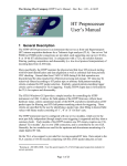
1
SENS - TECH
SENSOR TECHNOLOGIES
LINX
Linear X-ray detector
Sens-Tech Limited
6A Langley Business Centre
Station Road, Langley, Berkshire
SL3 8DS. UK
tel:
+44 (0) 1753 214714
fax:
+44 (0) 1753 214715
email: [email protected]
www.sens-tech.com
registered in England 668759
an ISO 9001 registered company
© Sens-Tech Limited, 2010
the contents may not be copied or disclosed to any
unauthorised third party without written permission
user manual
Contents
1
Scope of manual
1.1 General description
1.2 Features
1.3 Applications
2
Specification
3
Precautions
4
LINX hardware description
4.1 Internal arrangement and description of X-ray detection system
4.2 Power supply
4.3 Data interfaces
5
LINX system operation
5.1 Data acquisition
5.2 Data output
5.3 External trigger (nSCAN)
6
Hardware set-up
6.1 Connections
6.2 DIP switch settings
7
System installation
7.1 System requirements
7.2 Interfaces
7.3 Software installation
7.4 Software operation
8
Start-up software
8.1 Settings
8.2 Command interpreter
8.3 X-ray data acquisition
9
Advanced user guide
9.1 The control channel
9.2 The data channel
9.3 Additional configuration jumpers
10
Appendices
A. Data bus connections
B. System (data) bus wave forms
C. Internal cable connections
D. USB2.0 protocol details
E. Photodiode array details
LINX User Manual
Issue 1 (S00363)
17 August 2010
Page 1 of 36
©Sens-Tech Limited 2010
1. Scope of manual
This manual describes the design and operation of the LINX range of X-ray detector systems,
manufactured by Sens-Tech Ltd for use in X-ray linescan imaging systems. It covers both
hardware and software set-up and describes the software and hardware interfaces.
1.1 General description
LINX is a linear X-ray sensor which uses Sens-Tech X-ray detector boards to provide an array of
any required length. Detector pitch can be 2.5mm, 1.6mm, 0.8mm or 0.4mm. X-rays are
detected using silicon photodiodes, with a range of scintillation materials. Gadox (Gd2S2O), CsI
(Tl) and CdWO4 are used to cover the X-ray energy range of 20keV to 300keV.
The LINX unit housing is aluminium alloy with additional lead screening to protect the electronic
components from radiation damage. The unit has a collimator with a graphite window, so that
only a narrow X-ray beam can reach the detector, reducing scattering and improving image
quality.
The unit provides a 16-bit digital output. The system can be interfaced to a PC via:
USB2 Local (5m maximum cable length)
USB2 Remote (uses SCSI cable and external USB2 converter, up to 100m cable length)
PCI-7300A data I/O card (uses SCSI cable up to 100m cable length)
Frame grabber card (uses SCSI cable up to 100m cable length)
Control signals are transmitted to the unit via the USB2 connection or the RS232 serial port.
Standard software is supplied to permit basic operation and evaluation of the system. The
software enables single lines of data to be acquired and stored, data acquisition time to be set
and offset and gain correction to be applied. This is described in Section 8.
Users will normally wish to write their independent software application to provide system control,
data acquisition and image processing. To assist this task an Advanced User Guide is included
in Section 9 and an SDK (software development kit) is available. The SDK includes the data
acquisition source code.
1.2 Features
•
•
•
•
•
•
•
•
•
wide range of array lengths
2.5mm, 1.6mm, 0.8mm and 0.4mm array pitches
range of scintillator types
simultaneous data acquisition and read-out, minimal dead time
dual energy option
continuous or externally triggered scan
16 bit output
range of interface options
remote operation – up to 100m from PC to array
LINX User Manual
Issue 1 (S00363)
17 August 2010
Page 2 of 36
©Sens-Tech Limited 2010
1.3
Applications
These include security inspection, food inspection, non-destructive testing, thickness
measurement and medical. The arrays can be used both for linescan and CT (computerised
tomography) systems although other detector configurations, with detector boards arranged
around a ring, are generally more suited to CT systems.
2. Specification
mechanical
A separate outline drawing is provided with each system supplied.
electrical
Integration time, single sample
Sub-samples
Signal-to-noise
Non-linearity
Maximum data read-out rate
A/D Conversion
Data output
RS485 interface
Power
10µs to 50ms
1, 2 or 4 sub-samples
up to 30000:1 depending on system set-up
better than 0.1% over 90% of the dynamic range
20MHz (2.5, 5 and 10MHz also available) 1 byte per CLK
14 bit
16 bit (allows for up to 4 sub-samples)
9600 baud, 8 data bits, odd parity, 1 stop bit
6V to 9V, current depends on number of boards in the array.
environmental
temperature (operating)
humidity (non-condensing)
pressure for transportation
LINX User Manual
+5 to +35 °C
93 % at 30 ºC
can withstand pressure reductions from 100kPa (1 bar)
to 68kPA (0.68 bar)
Issue 1 (S00363)
17 August 2010
Page 3 of 36
©Sens-Tech Limited 2010
3. Precautions
supply voltage
Ensure the +6V supply voltage does not exceed +9V or fall below +5.5V. Exceeding these limits
may result in unpredictable behaviour. The power supply must not exceed the absolute
maximum ratings, this could cause permanent damage to the unit.
maintenance
There are no user maintainable components. The user must not attempt disassembly. The unit
must be returned to Sens-Tech for service or repair.
environment
The unit must not be exposed to levels outside those specified in Section 2
radiation
The unit uses components of limited radiation hardness.
protect the electronics from the X-ray source.
Additional shielding is required to
connections
Always make connections to the unit with the power supplies switched off.
4. LINX Hardware Description
A LINX unit consists of a set of XDAS, X-ray data acquisition boards, power distribution board
and data interface board mounted in a housing. The housing provides an electrically screened
enclosure, to eliminate interference from external electro-magnetic radiation. Lead screening is
also provided to prevent radiation damage.
A lead collimator is provided above the active detector area to improve the spatial resolution of
the detector and minimise internally scattered radiation.
The cover of the LINX unit is made of carbon fibre, to provide low X-ray absorption over the active
area, whilst maintaining the integrity of the electrical screen
LINX User Manual
Issue 1 (S00363)
17 August 2010
Page 4 of 36
©Sens-Tech Limited 2010
4.1 Internal arrangement and description of X-ray detection system
Typical LINX system internal layout
Collimator and lead shielding not shown
The main elements of the detection system are detector head boards, with X-ray detectors and
the signal processing board. This is shown in the schematic diagram above.
4.1.1
The detector head boards have multi-channel X-ray sensitive area detectors
connected to a charge integrating ASIC with 128 channels. For single energy
detector, there are X-ray detectors on one side of the boards only. For dual
energy detectors, with 1.6mm or 2.5mm pitch, there are detectors on both sides of
the board.
Single energy detector
LINX User Manual
Issue 1 (S00363)
17 August 2010
Page 5 of 36
Dual energy detector
©Sens-Tech Limited 2010
4.1.2
The X-ray detectors consist of silicon photodiode arrays with a range of scintillation
materials. Dual energy detectors may have a copper filter inserted between the low
energy and high energy detectors to provide an additional means of discrimination
between materials of different Z number.
Detector pitch options are 2.5mm, 1.6mm, 0.8mm and 0.4mm. See Appendix E for
drawings
Scintillator options are:
•
•
•
•
4.1.3
Gadox Gd2S2O for X-ray energies between 20keV and 100keV
CsI (Tl) between 100keV and 160keV
CdWO4 between 160kev and 300keV
Bare silicon (no scintillator) between 10keV and 20keV
The signal processing board provides the control signals to drive the detector
head board and converts the data into digital format, using a 14 bit ADC. The
firmware is contained in an FPGA, of the fused link type, to provide some protection
against radiation damage.
Signal processing board
The detector head boards and the signal processing boards are daisy-chained together
by a 50-way ribbon cable providing power and differential data and control signals. The
signal processing board is also connected to a data interface board, which puts data-in
and data-out lines into the correct format for connection with the processor via a 40 way
connector.
LINX User Manual
Issue 1 (S00363)
17 August 2010
Page 6 of 36
©Sens-Tech Limited 2010
4.2 Power supply
Power supply requirement is a maximum of 9V at the LINX detector box. Current requirements
are 175mA for each detector head board and 500mA for each signal processing board.
Power supplies are available from Sens-Tech
XDAS-PSU6
XDAS-PSU7
XDAS-PSU8
9V, 2A
9V, 5A
9V, 14A
Power leads are also available. They are fitted with sense wires so that the voltage at the input
to the LINX box can be monitored
LINXPOWER3M-04
LINXPOWER5M-04
LINXPOWER10M-04
LINXPOWER15M-04
LIMXPOWER25M
LINXPOWER35M
4.3 Data Interfaces
3 types of data interface are available, High speed data I/O using a PCI-7300A card, USB2.0 and
frame grabber.
•
The PCI7300A card requires an interface adaptor, XDAS-485A-TTL. This plugs into the
PCI card and is linked to the LINX data connection via a 50-way SCSI cable. The cable
can be up to 100m long.
•
The USB2 interface can be implemented in 2 ways, “local” with an adaptor board inside
the LINX box or “remote” with the standard interface board linked to a USB2 converter
box, XDAS-USB2, via a SCSI cable. With the “local” USB2 interface, the cable length to
the processor is limited to 5M. With “remote” USB2, the limit can be up to 100m long as
for the PCI7300A card.
•
A frame grabber card, Type PC-Dig, can be used. This requires an adaptor, XDAS485A-DFG to connect to the framegrabber card and a data converter, XDAS-CONV8-16
to convert data from the 8-bit output of the LINX unit to the 16-bit interface required by
the frame grabber.
LINX User Manual
Issue 1 (S00363)
17 August 2010
Page 7 of 36
©Sens-Tech Limited 2010
5. LINX System Operation
5.1 Data acquisition
When X-rays are incident on the X-ray detector, current is generated in the silicon photodiode
Detector head board
array. This is measured by a custom designed microcircuit containing 128 charge integrating
amplifiers and a multiplexer. Each amplifier channel has capacitors on which the charge is
stored.
Up to 24 detector head boards are linked to and controlled by signal processing board, shown
below.
Signal processing board
LINX User Manual
Issue 1 (S00363)
17 August 2010
Page 8 of 36
©Sens-Tech Limited 2010
System block diagram
Charge is acquired in the ASIC for the “signal integration time” which corresponds to the scan
time of the LINX detector. The ASIC provides two serial analogue outputs, corresponding to
amplifier output voltages at the beginning and end of signal integration. These are fed
sequentially via a differential amplifier, eliminating common mode noise, to a 14-bit ADC on the
signal processing board.
The system can operate in continuous mode with one set of data being read out while the next
set is being acquired. In continuous operation the dead time is less than 2 µs.
The maximum charge that can be collected per cycle depends on the choice of the storage
capacitors, one per channel, which are internal to the microcircuit. These can be set to 2pF or
10pF by adjustment of DIP switch G (see section 6.2). High linearity is maintained with a voltage
swing of 1.5 V providing charge storage of 3pC or 15pC per cycle. Sub-sampling is only
recommended to be used if the detector is in saturation with a single sample.
If higher dynamic range is required, a facility for sub-sampling and data summation is
incorporated on-board. Up to 4 sub-samples can be acquired and stored in the image data store,
which is a 16 bit device. When data is ready for transmission, the 16 bits are transmitted via the
chosen interface to the host CPU.
Operation is controlled by a gate array (FPGA) on the signal processing board, which provides
the central intelligence for the board and the timing and control signals for system operation. The
gate array is based on fused link technology, providing a degree of radiation hardness.
User settings to control integration times, sub-sampling, and refresh rate, together with
information on system configuration, are transmitted via an RS485 interface and can be stored in
non-volatile RAM such that on switch-on, the system is initiated in the last mode saved. The
RS485 is compatible with the RS232 serial port on standard PCs using the interface converter
supplied as part of the cable set.
LINX User Manual
Issue 1 (S00363)
17 August 2010
Page 9 of 36
©Sens-Tech Limited 2010
5.2 Data Output
Up to 12 detector boards can be daisy-chained to form a single detector system. Each SP board
can process two chains of 12 DH boards each. It is further possible to daisy chain up to 7 SP
boards. The first SP board in the system acts as the master board, ensuring that all boards in the
system are synchronised. The master board transmits the image data from all boards to the host
CPU via the RS485 link, see the system block diagram. It also transmits all control settings from
the host to the slave boards.
The data output bus is a differential RS485 link (multi-drop RS422) capable of transmitting at
2.5/5/10/20 MB/s. Interface to a PC is via USB2, PCI-7300A data I/O card or frame grabber card.
The same configuration of XDAS board is used for each mode but a different cable set is required
to connect to the PC. If USB2 mode is selected, no additional board is required for a PC. USB2
cable is capable of providing a single link for both data and control buses.
The signal processing boards share the multi drop system bus. One of either the speed of the
communications link or the ADC sample rate is normally the factor limiting data acquisition and
read-out rate for the system.
Sens Tech provides an XDAS-V2 system builder tool, available on request, for rapid system
configuration or alternatively, contact Sens-Tech for support and advice.
5.3 External trigger (nScan)
An external trigger facility is provided so that the unit can be given a hardware TTL start
command. There are two modes of operation:
Level Mode, whereby the unit runs continuously if nScan is Logic 0 and stops if nScan is Logic 1
Edge Mode, whereby the unit scans once on each rising and falling edge.
Mode selection is made by dip-switch selection on the signal processing board. This is
described in Section 6.2, hardware set-up
LINX User Manual
Issue 1 (S00363)
17 August 2010
Page 10 of 36
©Sens-Tech Limited 2010
6. Hardware set-up
6.1 Connections
USB remote connection diagram
USB local connection diagram
PCI connection diagram
LINX User Manual
Issue 1 (S00363)
17 August 2010
Page 11 of 36
©Sens-Tech Limited 2010
6.2 DIP switch settings
DIP switch A selects trigger (nSCAN) mode to be level or edge triggered. DIP switch G
selectes gain (2pF mode is high gain, 10pF mode is low gain.
The switch positions are shown below.
7. Software installation
The following instructions will enable users to operate the XDAS unit using the software provided.
Results can be taken immediately and the hardware setup can be checked for correct operation.
7.1 System requirements
Intel Pentium® III or faster CPU
(A USB2.0 capable PC is required for USB2 interface)
Microsoft Windows® 98, 2000 or XP
A mouse or a tablet
VGA or higher resolution monitor
CD drive
+6V low noise DC power supply
LINX User Manual
Issue 1 (S00363)
17 August 2010
Page 12 of 36
©Sens-Tech Limited 2010
7.2 Interfaces
The diagrams of appendix C show three different types of connection: USB2, PCI-7300A
and a frame grabber card connection.
7.2.1
control interface
Set up the serial interface as follows:
type
RS485
baud rate
9600
data bits
8
parity
odd
stop bits
1
USB2 connection does not require a separate serial interface.
7.2.2
data interface
One of three types of interface can be used: USB2; PCI-7300A Data I/O card or
frame grabber. These should be set up as follows:
USB2
type
USB 2.0
data rate
2.5 - 20 Mbytes per second sustained
mode
Bulk transfer mode.
Buffer
130kBytes of cache buffer
A standard USB B socket is used, conforming to industry standards.
PCI data I/O card
type
TTL, parallel 8 bit
data rate
2.5-20 Mbytes per second clocked using gated PCLK
mode
synchronous
Signal types and connector definition are detailed in appendix A.
Details of the synchronous protocol are defined in appendix B.
LINX User Manual
Issue 1 (S00363)
17 August 2010
Page 13 of 36
©Sens-Tech Limited 2010
Frame Grabber
Type
RS422, parallel 8 bit
data rate
2.5-20 Mbytes per second clocked using PCLK
mode
synchronous
Signal types and connector definition are detailed in appendix A.
Details of the synchronous protocol and line and frame synchronization are
defined in appendix B.
7.2.3
ID address
Dip switches are set on each signal processing module, based on the position of
each module in the system chain. For systems with only one processing board,
the address is always set to address 1. Note that address 0001 is the Master
Board.
address
7.2.4
address positions
(jumper or dip switch)
2
1
0
1
0
0
1
2
0
1
0
3
0
1
1
4
1
0
0
5
1
0
1
6
1
1
0
7
1
1
1
Board Header
The dip switch H is set to ON position. This enables the addition of two header
bytes in the beginning of each data block identifying each detector board. This
setting is required for XDAS software and is optional for customer specific
software.
LINX User Manual
Issue 1 (S00363)
17 August 2010
Page 14 of 36
©Sens-Tech Limited 2010
7.3 Software installation
Insert the XDAS software CD into the computer’s CD-ROM drive.
If the setup program does not auto-run, carry out the following:
• Select Run from the Start menu.
• In the command line box, type d:\setup (where d is the letter of your CD-ROM
drive), then click OK or press the Return key.
• Follow the on screen instructions.
• The setup program creates a program icon in the Start menu.
• Browse and click the XDAS Demo (V1x/V2) icon to start the program.
7.4 Software operation
On entering the program, the driver selection window is displayed first. Select the correct option
applicable to the type of data interface you are using and click OK. The software will then display
the Command Interpreter box and the Data Acquisition window.
The system is now ready to be used. Data acquisition parameters are set up on the Command
Interpreter and sent to XDAS using the Send button. The button turns green after a successful
XDAS configuration.
The system will commence data acquisition by pressing the Start button. Detailed setting-up
instructions can be found in section 8, Demonstration software.
8. Demonstration software
8.1 Settings
XDAS Software is provided with the unit to allow immediate use of the product. Custom user
programs may be required and Section 9, Advanced User Guide defines the necessary
interface protocol for users to follow.
These instructions are written for Microsoft Windows XP™. The software provided with the unit
can be operated by carrying out the following steps.
Before using the software the LINX must be connected to the power supply and to the host PC as
stated in Section 6, Hardware set-up.
A copy of the latest version of XDAS Demo software must be installed, (ref 7.3).
LINX User Manual
Issue 1 (S00363)
17 August 2010
Page 15 of 36
©Sens-Tech Limited 2010
Start the XDAS demonstration software by browsing to Start\All Programs\XDAS\XDAS Demo
(V1x). Select the applicable cable interface option in the driver selection window and click OK.
*The EPP mode is not
available on this system.
8.2 Command Interpreter
In the Command Interpreter set up the following default configuration
Graph mode
:
All
Integration period AB
:
50 (i.e., 500us)
Integration period CD
:
50 (i.e., 500us)
Subsamples
:
2
Test mode
:
unchecked
nModules
:
1x1
Host speed
:
5MHz
Refresh rate
:
10ms
Now click on the Send button which should turn Green indicating successful XDAS setup.
LINX User Manual
Issue 1 (S00363)
17 August 2010
Page 16 of 36
©Sens-Tech Limited 2010
8.2.1
Graph mode
The axis of the graph is automatically scaled to correspond to the total number of
channels depending on the number of modules in the system. The following
modes can be set via the Command Interpreter:
8.2.2
AB
This selects only channels 1 to 64 to be displayed from each module.
CD
This selects only channels 65 to 128 to be displayed from each module.
ALL
This selects all channels to be displayed in a single line.
Dual
This selects modes AB and CD to be displayed at the same time, as
different colours on the same x and y axis.
Scan control
This starts or stops the data acquisition process based on the last set of settings
sent from the Command Interpreter.
8.2.3
Integration period
This allows the user to set either identical or different integration periods for
channels 1 to 64 and 65 to 128 on each module. The integration period and can
be set between 1 and 50000 (10 µs to 0.5 s) in steps of 10us.
8.2.4
Test mode
This mode must only be used with the integration time set to a maximum of 30us
for 2pF mode and 150us for 10pF mode.
The test mode injects a factory defined signal into the odd and even inputs such
that the odd numbered channels produce an output twice to that of even
numbered channels. This feature allows the testing of the system in the absence
of an external signal.
8.2.5
Sub-sample
There is a choice of three different levels of sub-samples: 1, 2, and 4.
When Sub-samples is activated, multiple integration periods are taken
dependent on the number of sub-samples requested. This allows the dynamic
range of the module to be extended. The user may perform further sub-sampling
in software.
LINX User Manual
Issue 1 (S00363)
17 August 2010
Page 17 of 36
©Sens-Tech Limited 2010
8.2.6
Modules
This input tells both the hardware and the software how many modules are
connected in the system.
A
8.2.7
X
B
= Analogue x Digital
Refresh rate
This sets the software refresh rate for displaying new data and can be varied from
1 ms to 100 s.
8.2.8
Data log
When data logging is activated a separate menu is displayed requesting the file
name, number of data points required, and whether to add calibration data and
command interpreter settings. The system then logs data based on these
parameters and saves it in csv format.
8.2.9
Open last log file
This allows the last set of data to be logged or to be reloaded for analysis or
viewing.
8.2.10
Calibrate
The calibration mode allows the user to acquire offset and gain calibration
parameters. These are as follows:
offset: takes a reading based on the current settings and stores the figure for
each channel as the offset correction factor. This is carried out with no signal
present.
gain: takes a reading based on the current settings and calculates the gain
correction factor for each channel to give 95 % of full scale. This should be
carried out with maximum signal present on all channels.
The calibrate function allows 3 display options as follows:
offset correct: this automatically deducts the stored offset from all readings
before displaying and storing.
gain correct: this automatically calibrates with the stored gain correction factor
for each channel before displaying and storing.
set threshold: this allows all readings below a set number (0 to 65536) to be set
to zero, to allow for threshold detection.
The calibration factors can be applied to either live or static data.
LINX User Manual
Issue 1 (S00363)
17 August 2010
Page 18 of 36
©Sens-Tech Limited 2010
8.2.11
save defaults
This allows the current settings in the Command Interpreter to be set as the
module power-on defaults that are used on initial switch-on.
8.2.12
Send
This transmits the current parameters setup on the Command Interpreter screen
to the hardware. The Send box remains highlighted in Red if settings have been
changed and not transmitted to XDAS.
X-ray Data Acquisition
The following facilities are available from the X-ray Data Acquisition menu bar:
file
open:
enables the user to select a previous set of results for analysis.
save/save as:
enables the user to save a set of results.
settings:
allows the data and control interface to be selected as defined in section 3,
installation.
exit:
exits the program.
edit
copy:
LINX User Manual
copies data to the clipboard to enable it to be pasted into other software
applications, such as a spreadsheet or word processor.
Issue 1 (S00363)
17 August 2010
Page 19 of 36
©Sens-Tech Limited 2010
view
graph only:
displays graph only.
channel as:
channel/number: table referenced to channel numbers ( 1 to 8064 ) or
module/channel: table referenced as module and channel number
graph
(ie. 1/63 = module 1 channel 63 ).
type:
selects bar, line or bar/line combination display types.
window
data acquisition:
switches on/off the graphical display.
command interpreter:
switches on/off the command interpreter.
cascade:
allows data acquisition and command interpreter to be cascaded.
help
help:
future option. For help contact the Sens-Tech technical help line.
about:
opens a software information shield.
LINX User Manual
Issue 1 (S00363)
17 August 2010
Page 20 of 36
©Sens-Tech Limited 2010
9 Advanced User Guide
XDAS-V2 has two interface channels. These are the control channel and the data channel.
The control channel is used to issue commands to the XDAS system whereas the data channel
is used only to receive channel data from the XDAS system. In this section, hexadecimal
numbers are indicated by the prefix 0x.
9.1 The control channel
The control channel is used to issue commands to the XDAS system. It is an RS485 serial input
and is bussed to all the modules in the system. External connections to this bus are typically made
using pins 8 [SCTRL+] and 7 [SCTRL-] of the system bus connector.
9.1.1
command format
All commands sent to the XDAS system follow a generic pattern described below.
0xC0
Cmd
Data
All commands start with the byte 0xC0. This is followed by one or two byte(s)
representing the command (Cmd). Where a command has parameters, these are sent
immediately after the Cmd byte.
9.1.2
parameter format
There are two types of parameters that can be sent with a command. These are one byte
and two byte parameters.
one byte parameters are sent simply as one byte.
two byte parameters however, must be split into nibbles (half bytes) and sent as four
separate bytes. The most significant byte is sent first.
An example of this is given in section 9.1.4.
LINX User Manual
Issue 1 (S00363)
17 August 2010
Page 21 of 36
©Sens-Tech Limited 2010
9.1.3
command listing
The commands for controlling an XDAS system are shown below.
Command
byte
function
parameter type
(see section 5.1.2)
description
0x00
start scan
none
start continuous scan
0x01
stop scan
none
stop scan
default = OFF
0x02
set number of SP boards
one byte
sets the number of signal
processing boards in the
system
N = 1 to 7
default = 2
0x03 *
set integration period AB
two byte
sets the integration period for
block AB (ch1-64).
default = 68 (680us)
0x04
set output data bus speed
one byte
sets the PCLK frequency where
0=2.5, 1=5, 2=10, 3=20MHz
default = 2 (10MHz)
0x05
set sub-samples
one byte
sets the sub-samples, S where
N is the parameter.
N
S=2
default = 0 (1 ss)
0x06
test mode ON
none
enable test mode
default = OFF
0x07
Reserved
0x08 *
set integration period CD
two byte
sets the integration period for
block CD (ch65-128).
default = 68 (680us)
0x09
Reserved
0x0A
test mode OFF
none
disable test mode
default = OFF
0x0B
set number of DH boards
one byte
sets the number of detector
boards in the system.
N = 1 to 24
default = 12
0x0C
Reserved
0x0D
save boot defaults
none
Saves current settings as power
on defaults.
0x0E
Reserved
0x0F
Reserved
* the integration time, T, is derived from the integration period, P as follows: T = 10 µs x N
LINX User Manual
Issue 1 (S00363)
17 August 2010
Page 22 of 36
©Sens-Tech Limited 2010
9.1.4
example commands
Set number of sub-samples in system to 4
4=2
2
0xC0
0x05
0x02
Set integration period to 2600 (2600 = 0x0A28) on both AB and CD
0xC0
0x03
0x00
0x0A
0x02
0x08
0xC0
0x08
0x00
0x0A
0x02
0x08
Start Scanning
0xC0
9.1.5
0x00
scan trigger (nSCAN)
There is an option to start and stop the scan using hardware, for example, to synchronise
scanning to an X-Ray shutter.
nSCAN is a 5V CMOS signal (locally pulled high) and should be input to the first SP
board in the system. The module address does not matter. nSCAN is then bussed to
other modules over the system bus.
By default, nSCAN is a level triggered pin and as such, when nSCAN is Logic 0,
continuous scanning begins. When nSCAN is Logic 1, continuous scanning stops.
Switch A switches nSCAN from level
triggering to edge triggering on both rising
and falling edges.
Set
nSCAN edge
triggered
Not Set
nSCAN level
triggered
For edge triggering, there is one line acquisition and readout for each of the rising and
falling edges. The integration time and subsamples are set using the serial control
interface. XDAS ignores any nSCAN edges that appear while the current integration cycle
is in progress.
It is advised to use an opto-coupler to isolate nSCAN from XDAS if the trigger source is
referenced to a different ground plane.
LINX User Manual
Issue 1 (S00363)
17 August 2010
Page 23 of 36
©Sens-Tech Limited 2010
9.2
The data channel
The data channel is used to receive channel data from an XDAS system. It is an 8-bit
wide, RS485 (differential) parallel data bus running through all signal processing modules
in the system.
In a multi-processor system, the external connection between the XDAS system is made
from the module with the highest address and not from the module with address 1. The
modules send their data in order of address, starting at address 1.
9.2.1
DIP switches affecting the data transfer protocol
The data transfer protocol is set up using dip switches B, C, F, and H.
switch B allows the user to change the order
of channel readout from each detector board.
Set
readout reversed
Not set
standard output
switch C allows the user to change the order
of detector board readout from each signal
processing board.
Set
readout reversed
Not set
standard output
switch F switches the gated pixel clock
(PCLK) mode. When PCLK is gated, PCLK
only clocks valid data. When PCLK is ungated, PCLK clocks continuously. In ungated mode, LVAL ± is used to validate the
data. Un-gated mode is normally used for
frame-grabber cards. The un-gated mode is
available only in single SP board systems.
Set
PCLK ungated
Not set
PCLK gated
switch H controls the address header prefix.
When enabled, two header bytes are prefixed
to each packet data per module. The first
bytes represents the SP board ID and the
second byte represents the DH board ID.
This enables software to verify that it is in
sync with the data.
Set
header prefix
enabled
Not set
header prefix
disabled
DIP switches B and C allow to user to set XDAS to one of all the possible combinations of
the readout direction.
LINX User Manual
Issue 1 (S00363)
17 August 2010
Page 24 of 36
©Sens-Tech Limited 2010
9.2.2
data format
Data bytes are presented on the data output connector. The data from each module is
organised as shown below. The channels are output in order from 1 to 128. Channel data
is two bytes wide.
If switch H is set, a two byte header is added to the output of each module. The header
contains the address of the signal processing board (m) in the first byte and the module
number (n) in the second.
For example, data output for the first DH board connected to first SP board with switch H
(two header bytes) and switch E (digital test pattern enable – section 5.3) are set to ON is
given below.
SP
address*
DH
address*
CH1 Data
0x0m
0x0n
low byte
0x01
0x01
0x00
CH128 data
high byte
0x00
low byte
0xFC
high byte
0x01
The test mode changes when the readout order is changed using switch B and switch C
corresponding to data from different RAM locations. The header bytes remain the same.
9.2.3
synchronous mode
Data is output synchronised to PCLK, running at 2.5/5/10/20 MHz. This allow up to
20Mbytes/s data output. Both USB2 and PCI7300 interfaces are able to meet these
requirements.
J1 & J2
37
PCLK -
38
PCLK +
Data must be read from the data pins on the NEGATIVE edge of PCLK.
LINX User Manual
Issue 1 (S00363)
17 August 2010
Page 25 of 36
©Sens-Tech Limited 2010
9.3 Additional configuration jumpers
Switch D is for factory testing only. This
forces the system to boot from hardware
defaults and is useful if saved boot data is
corrupted.
Not set
switch E causes the ADC to be
disconnected and replaced by a known
incrementing digital test pattern (a ramp
function). All data processing is performed
on this data in exactly the same way as if it
were real ADC data, enabling the digital
electronics to be tested.
Set
test pattern ON
Not set
test pattern OFF
switch G is used to change the integration
capacitance on the front end charge
integration amplifiers.
Set
2 pF
Not set
10 pF
LINX User Manual
Issue 1 (S00363)
17 August 2010
Page 26 of 36
©Sens-Tech Limited 2010
10 Appendices
appendix A
data bus connections, 50 way SCSI interface adapters XDAS-DATA3, XDAS-DATA4 or XDAS-DATA6
Pin
1
2
3
4
5
6
7
8
9
10
11
12
13
14
15
16
17
18
19
20
21
22
23
24
25
26
27
28
29
30
31
32
33
34
35
36
37
38
39
40
41
42
43
44
45
46
47
48
49
50
Designation
RES
VBUS
PCLK+
VBUS
LVAL+
NC
RES
NC
D0+
NC
D1+
NC
D2+
NC
D3+
DC
D4+
NC
D5+
NC
D6+
GND
D7+
GND
SCTRL+
RES
VBUS
PCLKVBUS
LVALNC
RES
NC
D0NC
D1NC
D2NC
D3NC
D4NC
D5NC
D6GND
D7GND
SCTRL-
LINX User Manual
Description
Reserved for system use
5V bus supply
Pixel clock
5V bus supply
Line valid
No connection
Reserved for system use
No connection
Data bit 0
No connection
Data bit 1
No connection
Data bit 2
No connection
Data bit 3
No connection
Data bit 4
No connection
Data bit 5
No connection
Data bit 6
Ground
Data bit 7
Ground
Serial control
Reserved for system use
5V bus supply
Pixel clock
5V bus supply
Line valid
No connection
Reserved for system use
Not connected
Data bit 0
Not connected
Data bit 1
Not connected
Data bit 2
No connection
Data bit 3
No connection
Data bit 4
No connection
Data bit 5
No connection
Data bit 6
Ground
Data bit 7
Ground
Serial control
Issue 1 (S00363)
17 August 2010
Page 27 of 36
Signal Type
DC
RS485
DC
RS485
RS485
RS485
RS485
RS485
RS485
RS485
RS485
DC
RS485
DC
RS485
DC
RS485
DC
RS485
RS485
RS485
RS485
RS485
RS485
RS485
RS485
DC
RS485
DC
RS485
©Sens-Tech Limited 2010
appendix B
system (data) bus waveforms
These clock pulses are not present if PCLK is gated with LVAL. The un-gated PCLK mode is only
available in a single SP board system. Two header bytes are transmitted only if enabled using DIP switch
H. The first byte is the SP board ID and the second byte is the DH board ID.
LINX User Manual
Issue 1 (S00363)
17 August 2010
Page 28 of 36
©Sens-Tech Limited 2010
appendix B (continued)
LINX User Manual
Issue 1 (S00363)
17 August 2010
Page 29 of 36
©Sens-Tech Limited 2010
System readout direction is fully programmable using
switch B and switch C on the signal processing
boards, regardless of module interconnection. Please
refer to section 5.2 of this manual.
appendix C
cable interconnections
High speed data I/O PCI‐7300A connections
LINX User Manual
Issue 1 (S00363)
17 August 2010
Page 30 of 36
©Sens-Tech Limited 2010
System readout direction is fully programmable using
switch B and switch C on the signal processing boards,
regardless of module interconnection. Please refer to
section 5.2 of this manual.
appendix C (continued)
Frame grabber connections
LINX User Manual
Issue 1 (S00363)
17 August 2010
Page 31 of 36
©Sens-Tech Limited 2010
appendix C (continued)
USB2 local connections
LINX User Manual
Issue 1 (S00363)
17 August 2010
Page 32 of 36
©Sens-Tech Limited 2010
appendix C (continued)
USB2 remote connections
LINX User Manual
Issue 1 (S00363)
17 August 2010
Page 33 of 36
©Sens-Tech Limited 2010
appendix D
USB2 protocol
USB2.0 high speed mode
Bulk transfer protocol for data acquisition
Integrated control and data interface
XDAS SDK library files available with example code
LINX User Manual
Issue 1 (S00363)
17 August 2010
Page 34 of 36
©Sens-Tech Limited 2010
appendix E
photodiode array details
0.4mm pitch bare silicon detector
0.4mm pitch GADOX detector
LINX User Manual
Issue 1 (S00363)
17 August 2010
Page 35 of 36
©Sens-Tech Limited 2010
appendix E (continued)
LINX User Manual
Issue 1 (S00363)
17 August 2010
Page 36 of 36
©Sens-Tech Limited 2010