1
Page 6
Installation
recommends using a cooling fan to set up a positive air flow around the camera, and following the
precautions below:
•
Mount the camera on a large heat sink (camera bracket) made out of a conductive material such as
aluminum.
•
Make sure the flow of heat from the camera case to the bracket is not blocked by a non-conducting
material like plastic.
•
Make sure the camera has enough open space around it to facilitate the free flow of air.
2.2.2
2.2.2 (a)
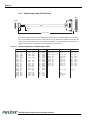
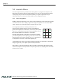
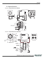
FIGURE 3.
Connector Pin Configurations
12-Pin Connector (TM-1402)
12-Pin Connector on Rear Panel of Camera
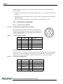
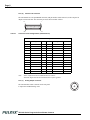
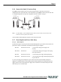
The TM-1402 has a 12-pin Hirose connector for power input, serial
communication, and signal integration. Pin #1 is Ground and Pin #2 is
+12V DC. Other pins handle a number of input and output functions,
as shown in Table 1 below.
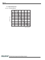
TABLE 1.
12-Pin Connector (TM-1402)
2.2.2 (b)
Pin
Description
Pin
1
GND (power)
7
VD In
2
+12V DC
8
Reserved
3
GND (analog)
9
HD In
4
Video Out
10
RXD (RS-232)
5
GND (digital)
11
N/C
6
VINIT In
12
TXD (RS-232)
1
2
3
9
11
4
8
10
7
12
5
6
Description
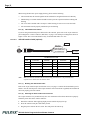
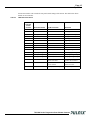
12-Pin Connector (TM-1402CL)
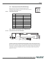
The TM-1402CL has a 12-pin Hirose connector for power input and signal integration. Pin #1 is Ground
and pin #2 is +12V DC. The pinout table is shown below. For the TM-1402CL, serial communication
camera control is done via the MDR26 Camera Link connector on the rear panel of the camera.
TABLE 2.
12-Pin Connector (TM-1402CL)
Pin
Description
Pin
Description
1
GND (power)
7
VD in
2
+12V DC
8
Reserved
3
GND (analog)
9
HD in
4
Video out
10
N/C
5
GND (digital)
11
N/C
6
VINIT in
12
N/C
TM-1402 Series Progressive Scan Shutter Cameras