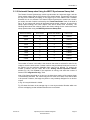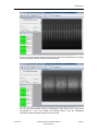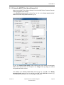
1
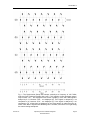
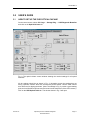
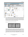
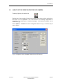
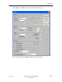
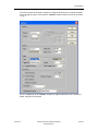
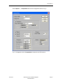
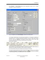
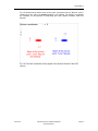
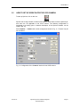
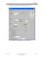
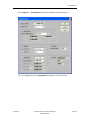
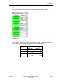
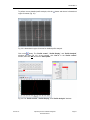
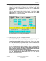
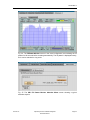
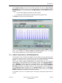
Optical Synchrotron Radiation Diagnostic Beamline Manual 7.9.79.1 Rev. 7 Date: 2015-05-12 Copyright 2015, Canadian Light Source Inc. This document is the property of Canadian Light Source Inc. (CLSI). No exploitation or transfer of any information contained herein is permitted in the absence of an agreement with CLSI, and neither the document nor any such information may be released without the written consent of CLSI. Canadian Light Source Inc. 44 Innovation Boulevard Saskatoon, Saskatchewan S7N 2V3 Canada Signature Date Original on File – Signed by: Author Staff Scientist, Instrumentation Reviewer #1 Accelerator Physicist Reviewer #2 AOD Manager Approver CID Manager The current version of this document is accessible under the Approved Documents section, on the CLSI Team Site. Employees must verify that any printed or electronically downloaded copies are current by comparing its revision number to that shown in the online version. 7.9.79.1 Rev. 7 TABLE OF CONTENTS 1.0 2.0 Introduction ................................................................................................ 1 1.1 Purpose and Scope ....................................................................................... 1 1.2 Background.................................................................................................... 1 1.3 Definitions and Abbreviations ......................................................................... 1 Description ................................................................................................. 2 2.1 Vacuum / Machine Protection ........................................................................ 2 2.2 Source Point .................................................................................................. 2 2.3 Photon Shutter ............................................................................................... 2 2.4 Optical Chicane ............................................................................................. 2 2.4.1 Photon Absorber ................................................................................ 2 2.4.2 Primary Mirror .................................................................................... 2 2.4.3 Beam Stop ......................................................................................... 3 2.4.4 Secondary Mirror ................................................................................ 3 2.4.5 Slit Assembly ...................................................................................... 3 2.4.6 Lens ................................................................................................... 3 2.4.7 Controls for the Optical Chicane ......................................................... 4 2.4.8 Fill Pattern Monitor ............................................................................. 4 2.5 Resolution ...................................................................................................... 4 2.6 Optical Elements on the Optical Table ........................................................... 5 2.7 2015-05-12 2.6.1 Shutter ............................................................................................... 5 2.6.2 Beam Splitters .................................................................................... 5 2.6.3 Fixed Mirror ........................................................................................ 5 2.6.4 Neutral-Density Filters ........................................................................ 5 2.6.5 Focusing Lenses ................................................................................ 5 2.6.6 Dove Prism......................................................................................... 5 2.6.7 Bandpass Filters................................................................................. 6 2.6.8 Fast Steering Mirror ............................................................................ 6 Detectors on the Optical Table ....................................................................... 6 2.7.1 CCD Camera ...................................................................................... 6 2.7.2 CCD Camera in the FSM Line ............................................................ 6 2.7.3 Position Sensitive Detector in the FSM line ........................................ 6 2.7.4 Intensified CCD (ICCD) ...................................................................... 6 Optical Synchrotron Radiation Diagnostic Beamline Manual Page i 7.9.79.1 Rev. 7 2.7.5 3.0 Streak Camera ................................................................................... 7 2.8 Local Monitors and Displays .......................................................................... 9 2.9 Test Equipment ............................................................................................ 10 User’s Guide ............................................................................................ 11 3.1 How to Set up the OSR Optical Chicane ...................................................... 11 3.2 How to Set up Spiricon for the CCD Camera ............................................... 14 3.3 Using the CCD Camera to Steer the Beam .................................................. 19 3.4 Interpreting the CCD Images ....................................................................... 19 3.5 How to Set up Spiricon for the ICCD Camera .............................................. 21 3.6 Controlling the ICCD Camera....................................................................... 25 3.7 How to Run the ICCD Camera ..................................................................... 26 3.7.1 Studies of the Stored Beam .............................................................. 26 3.7.2 Studies of the Injected Beam ............................................................ 26 3.8 Interpreting the ICCD Images ...................................................................... 27 3.9 How to Operate the Fast Steering Mirror ...................................................... 27 3.10 How to Set up the Streak Camera................................................................ 28 3.11 How to Run the Streak Camera ................................................................... 29 3.11.1 Using the M5675 Synchroscan Sweep Unit ...................................... 31 3.11.2 Horizontal Sweep when Using the M5675 Synchroscan Sweep Unit 34 3.11.3 Using the M5677 Slow Speed Sweep Unit ....................................... 36 3.11.4 Horizontal Sweep when Using the M5677 Slow Speed Sweep Unit . 37 3.11.5 Vertical Sweep when Using the M5677 Slow Speed Sweep Unit ..... 38 3.11.6 Analog Integration ............................................................................ 40 3.11.7 Profiles ............................................................................................. 40 3.11.8 Display Options ................................................................................ 42 3.11.9 Injection Studies with the Streak Camera in Synchroscan Mode ...... 42 3.12 How to Set up the Fill Pattern Monitor .......................................................... 43 3.13 How to Run the Fill Pattern Monitor ............................................................. 45 4.0 References ............................................................................................... 46 Revision History .................................................................................................. 47 2015-05-12 Optical Synchrotron Radiation Diagnostic Beamline Manual Page ii 7.9.79.1 Rev. 7 1.0 INTRODUCTION 1.1 PURPOSE AND SCOPE This manual describes the design and operation of the Canadian Light Source Optical Synchrotron Radiation Diagnostic Beamline (OSR). It describes the procedure for setting up the optical chicane and it summarizes the parameters for setting up the instruments on the optical table for the various measurements that can be made on the beamline. These parameters are intended to provide a reasonable starting point for any of the measurements, not a complete list of all possible settings. Also, the interpretation of the data is beyond the scope of this manual. It is assumed that the operator of the beamline is familiar with the layout of the facility and the beamline (see Ref. [1]), and knows how to use an oscilloscope and a multimeter. Familiarity with the CLS control system and with Microsoft Windows is also required. The CCD camera, the fast steering mirror, and the fill pattern monitor are simple devices, which can be operated with the information given in this document. The ICCD camera can be operated with the information given in this document and in the ICCD operating manual [3]. The streak camera is a complex and expensive device. This document gives some instructions on setting up the streak camera, but these are meant as a reminder for the experienced operator. In-depth hands-on training is required to operate the streak camera, as well as a good theoretical understanding of its principle of operation (see Ref. [4]). 1.2 BACKGROUND The Optical Synchrotron Radiation (OSR) beamline is located on port 02B1.2 (see Ref. [1]). This beamline is used to monitor storage ring characteristics using visible light. In normal operation the instrumentation is accessed from the control room. Access to the beamline hutch is required to configure and start up the streak camera and the fast steering mirror. Users will have access to the image off the CCD camera. 1.3 DEFINITIONS AND ABBREVIATIONS APD: Avalanche Photodiode BPM: Beam Position Monitor CCD: Charge-coupled Device CFD: Constant Fraction Discriminator FSM: Fast Steering Mirror KVM: Keyboard/Video/Mouse OSR: Optical Synchrotron Radiation PSD: Position Sensitive Detector TDC: Time-to-Digital Converter XSR: X-ray Synchrotron Radiation X,Y,Z: A right-handed system of coordinates defined such that Y is up and the beam travels in the Z direction. Therefore X is left when looking downstream, i.e. in the OSR hutch the storage ring is in the -X direction and the Far-IR hutch is in the +X direction. 2015-05-12 Optical Synchrotron Radiation Diagnostic Beamline Manual Page 1 7.9.79.1 Rev. 7 2.0 DESCRIPTION 2.1 VACUUM / MACHINE PROTECTION Vacuum control is identified on the P&ID. Vacuum / machine protection includes: 2.2 Interlocking of cold cathode gauges, thermocouple gauges, residual gas analyzers, and pumps to valve operation in the event of a vacuum loss. Because of the lack of an actual front-end on this beamline the machine protection function is implemented with the storage ring machine protection system. Allowing a valve to be opened only if the differential pressure across the valve is below a specified threshold. SOURCE POINT The source point is at an angle of 5º into dipole 02B1. 2.3 PHOTON SHUTTER The shutter is protected by stopping the electron beam in the storage ring if the cooling water flow is less than 35% (FLT1402-B10-01). Motion control of the shutter in and out of the beam is provided by a pneumatic cylinder, a pneumatic control valve and two position sensing switches. The shutter can only be opened when the vacuum valve is open. 2.4 OPTICAL CHICANE 2.4.1 Photon Absorber A photon absorber is located 1.957 m from the source point. Its aperture is 12 mm in X and 16 mm in Y. This corresponds to an angular acceptance of θx = 6.13 mrad and θy = 8.18 mrad. The transmitted beam power, integrated vertically, is approximately 70 W/mrad (horizontally) at 500 mA. Therefore, the total power passing through the photon absorber is about 430 W at 500 mA. 2.4.2 Primary Mirror The primary mirror is located 5 m from the source point. It only intercepts the visible light in the upper half of the synchrotron light cone. The mirror consists of aluminum-coated glidcop with a 200 nm SiO2 coating. The SiO2 8 coating is specified to withstand 10 R without noticeable darkening. The mirror is watercooled with a liquid gallium layer as thermal coupling. The size of the mirror is 50 mm ∙ 50 mm. The mirror can be moved in and out of the beam at a fixed angle of 45º. A thermal probe with two K-type thermocouples is attached to the lower edge of the primary mirror. The mirror is protected by closing the front-end photon shutter: If the cooling water flow is less than 30% (FLT1402-B10-02), If either or both of the thermal probe temperatures exceed 50ºC (TM1402-B10-04, TM1402-B10-05). 2015-05-12 Optical Synchrotron Radiation Diagnostic Beamline Manual Page 2 7.9.79.1 Rev. 7 2.4.3 Beam Stop The beam stop is protected by closing the front-end photon shutter: If the cooling water flow is less than 30% (FLT1402-B10-03), If the return water temperature exceeds 28ºC (TM1402-B10-03). 2.4.4 Secondary Mirror The secondary mirror is located 5.5 m from the source point. It is identical to the primary mirror, except for the water cooling and the temperature monitoring. It can be moved in the following manner: Vertical translation, Rotation about the horizontal axis, Rotation about the vertical axis. In normal operation the secondary mirror is tilted 45º about its horizontal axis. However, it can be turned perpendicular to the optic centre line so that light from the optical table is reflected back to the table. 2.4.5 Slit Assembly The slit assembly is located 5.615 m from the source point. It has 4 independent blades, but control of the blades is combined into “gap” and “centre” in both X and Y. The following settings are used in normal operation: Gap Centre X 22 mm 0 mm Y 30 mm 15 mm The Y gap allows all visible light to pass through the slits. The Y centre has an offset because the primary mirror only intercepts the upper half of the light cone (see 2.4.2). The X gap was determined empirically in order to optimize the resolution of the system, considering the spot size vs. diffraction from the slit. 2.4.6 Lens The lens is an achromat with a diameter of 150 mm and a nominal focal length of 3 m. It was found, however, that the true focal length is 2.965 m. Therefore the lens is located 5.93 m from the source point, 70 mm closer than the design position. This results in a magnification of 1 with the primary focus at a distance of 11.86 m from the source point. The lens is mounted on a 3 axis translation stage, but the motion in X and Y is disabled. The settings used in normal operation are: X 0 mm (fixed) Y 0 mm (fixed) Z 2015-05-12 -70 mm Optical Synchrotron Radiation Diagnostic Beamline Manual Page 3 7.9.79.1 Rev. 7 2.4.7 Controls for the Optical Chicane Rack R2405.1-04, located on top of the storage ring, contains the control hardware for the optical chicane. A K-type thermocouple (TM1402-B10-06) is mounted inside the optical chicane. This thermocouple is used to monitor and log the temperature inside the chicane. 2.4.8 Fill Pattern Monitor 2.4.8.1 Detector The detector is a Hamamatsu C5658 module consisting of an avalanche photodiode (APD), a bias supply and an amplifier. The detector has a bandwidth of 1 GHz and an active area 0.5 mm in diameter. The spectral response range is 400-1000 nm, but the module works well as a single-photon X-ray detector. The APD is located in the +X direction from the beam stop and detects X-ray luminescence from the beam stop. A brass absorber wedge on a motorized stage in front of the APD is used to adjust the count rate of the APD. 2.4.8.2 Readout The readout system consists of a constant fraction discriminator (CFD) and a time-todigital converter (TDC). The constant fraction discriminator (BL#/EE/DIAG/0072780/0072781) is a custom designed NIM module with a fixed constant fraction delay matched to the rise time of the APD, a fixed fraction of 0.25, and a fixed output pulse width of 5 ns. The dead time of the CFD is just under 10 ns. Therefore, after an X-ray is detected, the system is blind to photons from the following 4 bunches, but is able to detect an X-ray from the fifth bunch. The time-to-digital converter is a CAEN V1290N multi-hit VME TDC with a resolution of 25 ps. It measures the arrival time of an X-ray relative to the orbit clock of the storage ring. 2.5 RESOLUTION The resolution of the OSR line is determined by the following effects: Diffraction from the primary mirror (2.4.2) in Y and from the slits (2.4.5) in X, Depth of field, Dispersion of the electron beam, Curvature of the electron beam (X only). For the typical slit settings given in 2.4.5, the resolution in Y is 55 μm, which is mostly due to diffraction at the primary mirror (51 μm). In X the resolution is also 55 μm, with diffraction from the slits accounting for 48 μm. These are 1-σ values, which need to be subtracted in quadrature from the measured beam spot size in order to obtain the true beam spot size. Note: The beam spot size (typically 400 μm in Y and 700 μm in X) is given as 4-σ values, and needs to be divided by 4 before the resolution is subtracted in quadrature. 2015-05-12 Optical Synchrotron Radiation Diagnostic Beamline Manual Page 4 7.9.79.1 Rev. 7 2.6 OPTICAL ELEMENTS ON THE OPTICAL TABLE The layout of the optical table is captured in drawing 02B1-2/ME/OPT/009400. 2.6.1 Shutter In order to protect the cameras, the optical table is equipped with a shutter that closes automatically when any of the filter wheels are moved. 2.6.2 Beam Splitters There are three beam splitters on the optical table. The first one has 50% transmission toward the ICCD camera and the CCD camera, and 50% reflection toward the fast steering mirror or the streak camera. The second beam splitter is located in the ICCD/CCD line right behind the first splitter. It has 90% transmission toward the ICCD camera and 10% reflection toward the CCD camera. The third splitter is located in the FSM line and has 90% transmission toward the PSD and 10% reflection toward the CCD camera. 2.6.3 Fixed Mirror There is one fixed mirror in the streak camera line. It is a Newport 20D20BD.1. 2.6.4 Neutral-Density Filters There are four neutral-density filter wheels, one each for the CCD camera, the CCD camera in the FSM line, the ICCD camera, and the streak camera. The filters are Melles Griot absorptive neutral-density filters with a diameter of 25 mm and various optical densities. 2.6.5 Focusing Lenses There are 7 focusing lenses on the optical table, all of them achromatic doublets with a diameter of 50.8 mm. The FSM line uses point-parallel-point optics with two Newport PAC091 lenses (f = 500 mm). The ICCD line uses point-to-point optics with either an Oriel 42640 lens (f = 160 mm for a magnification M = 4) or a Newport PAC088 lens (f = 250 mm for a magnification M = 1) moved into position with pneumatic lifters. The streak camera line uses a fixed Newport PAC094 lens (f = 750 mm, point-to-parallel), and either a Newport PAC089 (f = 300 mm, parallel-to-point, magnification M = 0.4) or a Newport PAC086 (f = 150 mm, parallel-to-point, magnification M = 0.2). These two lenses are mounted on pneumatic lifters. 2.6.6 Dove Prism The vertical sweep of the streak camera draws a top view of the beam. In order to allow a side view of the beam, a dove prism is moved into the optical path. The dove prism is a Melles Griot 01PDE005. 2015-05-12 Optical Synchrotron Radiation Diagnostic Beamline Manual Page 5 7.9.79.1 Rev. 7 2.6.7 Bandpass Filters There is a Melles Griot 03FIB006 bandpass filter in front of each camera. The filters have a FWHM of 80 nm and are centred at 500 nm. The filter diameter is 50 mm. 2.6.8 Fast Steering Mirror The fast steering mirror is a Newport FSM-320-01 with a diameter of 50.8mm. 2.7 DETECTORS ON THE OPTICAL TABLE The optical table is a metric table, 1.2m ∙ 2.4m, with M6 holes on a 25 mm grid. It is equipped with four detectors. The layout of the detectors is captured in drawing 02B12/ME/OPT/009400. 2.7.1 CCD Camera The CCD camera is a COHU Model 6612-3000, configured for interlaced mode with a shutter speed of 1/60 s. The video signal is distributed to: A video monitor located in the OSR hutch, A video to Ethernet adapter, which is used to make the image available on a web page and on the facility monitors, A fibre link to the control room, A frame grabber in the OSR hutch. The digitized images from the frame grabber are analyzed by a software package called “Spiricon”. Although the computer running Spiricon is located in the OSR hutch, it can be accessed from the control room via a KVM extender. The wiring of the CCD camera is shown in O2B1-2/EE/WIR/0090780. 2.7.2 CCD Camera in the FSM Line An identical CCD camera is mounted in the FSM line. It uses the same readout as described in 2.7.1 (the video signal cable is moved between the two cameras). 2.7.3 Position Sensitive Detector in the FSM line The detector is a Hamamatsu Model S1300 duo-lateral, super linear position sensing detector mounted on a C4757 signal processing board. It is used to provide position feedback to the fast steering mirror controller. 2.7.4 Intensified CCD (ICCD) The intensified CCD (ICCD) camera provides bunch-by-bunch or single bunch position analysis of the beam. It is a 4 Picos camera running in interlaced mode and it includes a software package to control it. This software runs on a computer in the OSR hutch, but remote control from the control room is available via a KVM extender. The camera is connected to a frame grabber, and the Spiricon software (see 2.7.1) is used to analyze the images. The camera is normally triggered by the storage ring synchronous trigger, but the storage ring injection trigger is available for injection studies, and a dump trigger is available for 2015-05-12 Optical Synchrotron Radiation Diagnostic Beamline Manual Page 6 7.9.79.1 Rev. 7 studies of the beam decay after an RF trip. The trigger is selected by moving the ICCD trigger cable to the appropriate spigot on P1602.1-02 (see O2B1-2/EE/WIR/0090780). The trigger circuit of the camera ignores trigger signals that are sent while the camera is not ready to accept them. However, experience shows that the camera should not be triggered at a rate > 200 Hz, in order to avoid temperature drifts in the trigger circuit. A pre-scaler (BL#/EE/DIAG/0106150) is used to divide down the trigger rate when running with the storage ring synchronous trigger. The range of exposure times is 200 ps to 80 s, although in this application it is usually not practical to exceed exposure times of 100 s, because the light intensity would be too high. Nevertheless, it is possible to acquire images of a single bunch or, at the other extreme, average over hundreds of turns. The camera has a built-in delay of 0 s to 80 s in steps of 100 ps. Again, only the bottom end of the range is practical in this application. The delay can be used to select a single bunch or the start of a sequence of bunches, or to select a turn during injection studies. Note: A delay of approximately 163 s needs to be set to select the first turn after injection. For injection studies, the storage ring RF needs to be turned off, since the ICCD would otherwise be blinded by the stored beam. 2.7.5 Streak Camera The purpose of the streak camera is to monitor the state of individual bunches: Measure the bunch length, Observe the bunch from the top or the side, Monitor the bunch for unstable motion. The streak camera is a Hamamatsu C5680-31 camera with a cathode height of 500 m and with A1976-01 broadband input optics. It has an RS170 video output connected to a frame-grabber, and is controlled by the vendor-provided “HPD-TA9” software package through a GPIB interface. The wiring diagram for the streak camera is shown in 02B2-02/EE/MON/WIR/0108280. The camera has the following plug-ins: 2.7.5.1 M5675 Synchroscan Sweep Unit The Synchroscan Sweep Unit has a vertical sweep frequency of 166.7 MHz (1/3 fRF). It is synchronized with the storage ring RF frequency fRF, and therefore paints every third bunch in the storage ring (see Fig. 1) while the other bunches arrive when the vertical sweep is above or below the screen. Since the harmonic number of the storage ring (=285) is divisible by 3, the Synchroscan Unit paints the same subset of 95 bunches in every turn, i.e. either bunches 1,4,7,...,283 (Fig. 1(a)), or 2,5,8,...,284 (Fig. 1(b)), or 3,6,9...,285 (Fig. 1(c)). The 166.7 MHz signal to the Synchroscan Unit is delayed in a Hamamatsu C1097-04 Delay Unit. The beam bunches can be positioned on the screen by making small adjustments to the delay setting. The desired subset of bunches can then be chosen by increasing or reducing the delay setting in steps of 2 ns (Fig. 1(a), 1(b), 1(c)). Increasing or reducing the delay setting by 3 ns switches between painting the same subset of beam bunches on the up-stroke (Fig. 1(a)) or on the down-stroke (Fig. 1(d)). The 166.7 MHz signal is generated from the 500 MHz master oscillator signal in a divideby-3 module (CDAC/EE/TMNG/0090870). The 500 MHz sine wave is converted into a digital signal and divided by 3 in such a way that a square wave with a 50% duty cycle results. A low pass filter is then used to reject the higher harmonics, resulting in a 166.7 MHz sine wave. It now appears that the higher harmonics would be rejected by the input of the streak camera anyway, but at the time the circuit was designed (before delivery of the camera) this information was not available. 2015-05-12 Optical Synchrotron Radiation Diagnostic Beamline Manual Page 7 7.9.79.1 Rev. 7 Fig. 1: The Synchroscan Sweep Unit sweeps vertically at a frequency of 166.7 MHz, while the Dual Timebase Extender Unit (see 2.7.4.3) applies a linear horizontal sweep. Only bunches 1,4,7,... are displayed on the screen in graph (a). If the 166.7 MHz signal is delayed by 2 ns, bunches 2,5,8,... are displayed (b). If the signal is delayed by 4 ns compared to (a), bunches 3,6,9,... are displayed (c). If the signal is delayed by 3 ns compared to (a), all bunches are displayed on the down-stroke (d) rather than the upstroke. Note that no Synchronous Blanking Unit is needed, since there is no light hitting the camera during sweepback. 2015-05-12 Optical Synchrotron Radiation Diagnostic Beamline Manual Page 8 7.9.79.1 Rev. 7 2.7.5.2 M5677 Slow Speed Sweep Unit The Slow Speed Sweep Unit is used to paint entire bunch trains. The unit is triggered by a signal that is derived from the storage ring synchronous trigger. The maximum trigger rate that the Slow Speed Sweep Unit can accept depends on the sweep speed setting. Trigger signals that arrive during the deadtime are ignored. However, unless the vertical trigger rate is an integer multiple of the horizontal trigger rate, the image produced by the camera walks horizontally. A pre-scaler (BL#/EE/DIAG/0106150) is therefore used to set the trigger rate low enough so that all triggers are accepted by the Slow Speed Sweep Unit. Also, the time delay between a trigger and the start of the vertical sweep depends on the sweep speed. A combination of a fibre delay and a NIM delay module is used to adjust the timing of the trigger signal in order to position the image on the screen. 2.7.5.3 M5679 Dual Timebase Extender Unit The Dual Timebase Extender Unit has a horizontal sweep frequency of 10 Hz or less, depending on the sweep speed. Trigger signals that arrive during the deadtime should be ignored. However, it was found that the behaviour of the trigger circuit is unpredictable when triggered during the deadtime. Furthermore, a synchronization problem was noticed between the camera and the frame grabber when the horizontal sweep and the frame grabber were triggered simultaneously as recommended by Hamamatsu. Both problems were addressed by building a Streak Camera Synchronizer module (BL#/EE/DIAG/0106190). It monitors the video signal of the streak camera and recognizes odd and even fields. It then divides the 30 Hz odd/even field frequency by a selectable number to obtain a horizontal trigger frequency <10 Hz. The timing of the horizontal trigger signal is then determined by the first pre-scaled storage ring synchronous trigger (see 2.7.4.2) to follow the pre-scaled odd/even field signal. This setup satisfies all of the following conditions: 2.8 No horizontal trigger signal arrives at the camera during its deadtime, The frame grabber is synchronized to the streak camera CCD and to the horizontal sweep, The vertical trigger rate is an integer multiple of the horizontal trigger rate (see 2.7.4.2). LOCAL MONITORS AND DISPLAYS The following monitors and displays are permanently installed in the OSR hutch: A rack-mounted video monitor connected to the CCD camera, A rack-mounted video monitor connected to the CCD camera in XSR, A rack-mounted computer monitor and keyboard tray, switched between the CCD/ICCD and streak camera data acquisition computers, A rack-mounted control computer for beamline control and other diagnostics, 2 Keithley 6485 Picoammeters, which are connected to the XSR X-ray BPM. 2015-05-12 Optical Synchrotron Radiation Diagnostic Beamline Manual Page 9 7.9.79.1 Rev. 7 2.9 TEST EQUIPMENT The following test equipment is dedicated to the OSR hutch: A 0.5 mW laser made by Research Electro Optics Inc., model # 31008, A Hamamatsu C8898 Picosecond Light Pulser with a peak power of 66 mW and a pulse duration of 70 ps, The “Canadian Light Source”, a battery powered, white LED mounted in a box with an ST connector, A Tektronix TDS3052B oscilloscope, 2 BK Precision 1856D 3.5 GHz frequency counters, A Fluke 87 handheld multimeter, A Tektronix AFG3101 Arbitrary / Function Generator, A Sony MHC-GX250 stereo system, which is used for acoustic vibration studies. 2015-05-12 Optical Synchrotron Radiation Diagnostic Beamline Manual Page 10 7.9.79.1 Rev. 7 3.0 USER’S GUIDE 3.1 HOW TO SET UP THE OSR OPTICAL CHICANE On the control screen, select CLS Logo → Storage Ring → OSR Diagnostic Beamline and click on the Optical Chicane tab. Fig. 2: The optical chicane control window showing the nominal settings for all optical elements. All the settings should be as shown in Fig. 2, otherwise correct the settings that are wrong. Open the vacuum valve first, and then the photon shutter. Use the CCD camera as a reference for aligning the beam. (Note: The settings in Fig. 2 provide a good starting point, but in all likelihood will not steer the beam into the active area of the CCD camera.) Click on the OSR Optical Table tab. The window shown in Fig. 3 will open. 2015-05-12 Optical Synchrotron Radiation Diagnostic Beamline Manual Page 11 7.9.79.1 Rev. 7 Fig. 3: The OSR Optical Table window. The table photon shutter is open and filter wheel B14-01 in front of the CCD camera is set to OD4. In the ICCD camera line at the bottom, both lenses are out and filter wheel B13-01 is set to OD4. In the streak camera line the dove prism is out, both lenses are out, and filter wheel B15-01 is set to OD4. Filter wheel B16-01 of the FSM line is set to OD4. The fast steering mirror is shown out of the beam, but it would be moved in manually when the FSM line is used. Select a reasonable OD setting for the CCD camera: Beam in the Storage Ring Optical Density 1 mA 0 10 mA 1 100 mA 2 200 mA 3 Open the table photon shutter. If the beam spot does not appear on the video monitor, close the table shutter again and look at the upstream side of the table shutter. There is a label on the table shutter, which indicates the nominal beam spot position. The actual spot should be visible somewhere on the table shutter. (Note: If the light above the optical table is dimmed, the spot is clearly visible at a beam current of a few mA). Steer the beam towards the nominal position using the “XY using rotation” arrows in the optical chicane control window (Fig. 2). This moves the secondary mirror. The direction of motion is: 2015-05-12 Optical Synchrotron Radiation Diagnostic Beamline Manual Page 12 7.9.79.1 Rev. 7 2015-05-12 XY Using Rotation TV Monitor Table Shutter Beam Coordinates ↑ ↓ ↑ +Y ↓ ↑ ↓ -Y → → ← +X ← ← → -X Optical Synchrotron Radiation Diagnostic Beamline Manual Page 13 7.9.79.1 Rev. 7 3.2 HOW TO SET UP SPIRICON FOR THE CCD CAMERA To start up Spiricon, click on the icon Spiricon has a large number of features and options. Some have not been explored yet, and some are not applicable to the CCD camera. The following configuration is suggested as a starting point. A detailed description of the Spiricon software can be found in Ref. [2]. Select Options → Camera and set the configuration shown in Fig. 4. “Frames” may be set as desired. Fig. 4: Configuration of the “Camera” window for the CCD camera. 2015-05-12 Optical Synchrotron Radiation Diagnostic Beamline Manual Page 14 7.9.79.1 Rev. 7 Select Options → Capture and set the configuration shown in Fig. 5: Fig. 5: Configuration of the “Capture” window for the CCD camera. 2015-05-12 Optical Synchrotron Radiation Diagnostic Beamline Manual Page 15 7.9.79.1 Rev. 7 The CCD camera can be used to capture an image of the beam at its “moment of death”, as the storage ring trips. In this case the “Capture” window needs to be set up as shown in Fig. 6. Fig. 6: Configuration of the “Capture” window for capturing the beam at its “moment of death” using the CCD camera. 2015-05-12 Optical Synchrotron Radiation Diagnostic Beamline Manual Page 16 7.9.79.1 Rev. 7 Select Options → Computations and set the configuration shown in Fig. 7: Fig. 7: Configuration of the “Computations” window for the CCD camera. 2015-05-12 Optical Synchrotron Radiation Diagnostic Beamline Manual Page 17 7.9.79.1 Rev. 7 Select Options → Beam Display and set the configuration shown in Fig. 8. “Curser Orientation” may be set as desired. Fig. 8: Configuration of the “Beam Display” window for the CCD camera. For a proper measurement of the beam size and position, it is important to subtract the background light. To start this background subtraction, close the table photon shutter (see Fig. 3) and click “Ultracal” in the Spiricon window. Open the table shutter again when the background measurement is finished (after a few seconds). Spiricon has 3 toolbars: The top toolbar is for triggering and sampling. It should be set as shown, with Σ and μ not pressed. The numbers to the right of Σ and μ are then meaningless. The middle toolbar defines the crosshairs and should be set as shown. The bottom toolbar describes the region of interest. The region of interest can be defined by entering coordinates or by dragging and resizing. The -button needs to be pressed to read meaningful values for the beam position or the beam size. 2015-05-12 Optical Synchrotron Radiation Diagnostic Beamline Manual Page 18 7.9.79.1 Rev. 7 3.3 USING THE CCD CAMERA TO STEER THE BEAM The following table lists the directions, in which the beam is steered, when the “XY Using Rotation” arrows are used. Normally, the “Lens” option in the Spiricon Camera window would not be checked. The beam direction at the table shutter is given as seen on the upstream side of the shutter, when the shutter is closed. XY Using Rotation TV Monitor Spiricon Spiricon “Lens” Option Table Shutter Beam Coordinates ↑ ↓ ↑ ↓ ↑ +Y ↓ ↑ ↓ ↑ ↓ -Y → → → → ← +X ← ← ← ← → -X Using Spiricon, set the centroid of the beam to X = 2500 μm and Y = 2500 μm. This is the reference beam position for all other devices on the Optical Table. 3.4 INTERPRETING THE CCD IMAGES Fig. 9 shows how the beam at the source point is projected onto the TV monitor. See section 1.3 for the definition of the beam coordinates. Fig. 9: The beam coordinates as they appear on the TV monitor for the CCD camera. 2015-05-12 Optical Synchrotron Radiation Diagnostic Beamline Manual Page 19 7.9.79.1 Rev. 7 Fig. 10 shows how the beam at the source point is projected onto the Spiricon screen. Usually the “Lens” flag in the Camera window is not checked. The Spiricon coordinates are indicated for the purpose of interpreting the beam position numbers read from Spiricon. Fig. 10: The beam coordinates as they appear in the Spiricon window for the CCD camera. 2015-05-12 Optical Synchrotron Radiation Diagnostic Beamline Manual Page 20 7.9.79.1 Rev. 7 3.5 HOW TO SET UP SPIRICON FOR THE ICCD CAMERA To start up Spiricon, click on the icon Spiricon has a large number of features and options. Some have not been explored yet, and some are not applicable to the ICCD camera. The following configuration is suggested as a starting point. A detailed description of the Spiricon software can be found in Ref. [2]. Select Options → Camera and set the configuration shown in Fig. 11. “Frames” may be set as desired. Fig. 11: Configuration of the “Camera” window for the ICCD camera. 2015-05-12 Optical Synchrotron Radiation Diagnostic Beamline Manual Page 21 7.9.79.1 Rev. 7 Select Options → Capture and set the configuration shown in Fig. 12: Fig. 12: Configuration of the “Capture” window for the ICCD camera. 2015-05-12 Optical Synchrotron Radiation Diagnostic Beamline Manual Page 22 7.9.79.1 Rev. 7 Select Options → Computations and set the configuration shown in Fig. 13: Fig. 13: Configuration of the “Computations” window for the ICCD camera. 2015-05-12 Optical Synchrotron Radiation Diagnostic Beamline Manual Page 23 7.9.79.1 Rev. 7 Select Options → Beam Display and set the configuration shown in Fig. 14. “Curser Orientation” may be set as desired. Fig. 14: Configuration of the “Beam Display” window for the ICCD camera. For a proper measurement of the beam size and position, it is important to subtract the background light. To start this background subtraction, close the table photon shutter (see Fig. 3) and click “Ultracal” in the Spiricon window. Open the table shutter again when the background measurement is finished (after a few seconds). Spiricon has 3 toolbars: The top toolbar is for triggering and sampling. It should be set as shown, with Σ and μ not pressed. The numbers to the right of Σ and μ are then meaningless. The middle toolbar defines the crosshairs and should be set as shown. The bottom toolbar describes the region of interest. The region of interest can be defined by entering coordinates or by dragging and resizing. The -button needs to be pressed to read meaningful values for the beam position or the beam size. 2015-05-12 Optical Synchrotron Radiation Diagnostic Beamline Manual Page 24 7.9.79.1 Rev. 7 3.6 CONTROLLING THE ICCD CAMERA This section describes how to initialize the ICCD camera for its most common mode of operation in the OSR beamline. For a detailed description of all the features of the camera, refer to the Operating Manual [3]. To open the camera control window, click on the icon: Click “Initialize”, “Connect”, then set the configuration shown in Fig. 15 and “Send it”. Set “Delay” and “Time” according to the specific measurement you want to make. Fig. 15: Control window for the ICCD camera. 2015-05-12 Optical Synchrotron Radiation Diagnostic Beamline Manual Page 25 7.9.79.1 Rev. 7 3.7 HOW TO RUN THE ICCD CAMERA To avoid drifts of the ICCD shutter time, let the camera warm up for about 20 min before using it. Turn off the lights above the optical table, pull the curtain, and dim the lights above the racks before removing the cap of the ICCD camera. 3.7.1 Studies of the Stored Beam Connect the “ICCD Trigger” cable to “Orbit” on panel P1601.1-02. Select the M=4 lens (see Fig. 3). Set the exposure time to 570 ns. Reduce the optical density of the neutral density filter (see Fig. 3) until an image of the beam appears. To find the first filled bucket, gradually reduce the exposure time to 1 ns while increasing the delay as required to keep the beam spot visible. Reduce the optical density of the filter if necessary. With the exposure time set to 1 ns, change the delay setting in 1 ns steps and watch the beam spot appear and disappear as you move from bunch to gap to bunch. If the beam spot does not disappear completely, change the delay setting by 0.5 ns and then repeat the 1 ns increments. Once a proper light/dark sequence is established, you can move from bunch to bunch by increasing/decreasing the delay by 2 ns. You can also change the number of bunches you are observing by increasing/decreasing the exposure time in 2 ns steps. 3.7.2 Studies of the Injected Beam Connect the “ICCD Trigger” cable to “Injection” on panel P1601.1-02. Select the M=1 lens (see Fig. 3). Inject beam with the storage ring RF turned off. Stored beam would blind the camera. Set the exposure time to 5.7 s and the delay to 163 s. In Spiricon, set the trigger type to “Video Trigger”. Reduce the optical density of the neutral density filter (see Fig. 3) until an image of the beam appears. Gradually reduce the exposure time to 570 ns. Adjust the delay if necessary. Also, reduce the optical density of the filter if necessary. With the exposure time set to 570 ns, change the delay setting in 570 ns steps and watch the beam spot jump as you move from turn to turn. If two locations are visible simultaneously, instead of the beam spot jumping from one location to another, two turns are observed in part. Adjust the delay. Reduce the delay in 570 ns steps until the beam spot disappears. Then increase the delay by 570 ns. This is turn 1. 2015-05-12 Optical Synchrotron Radiation Diagnostic Beamline Manual Page 26 7.9.79.1 Rev. 7 3.8 You can now move from turn to turn by increasing/decreasing the delay by 570 ns. You can also change the number of turns you are observing by increasing/decreasing the exposure time in 570 ns steps. INTERPRETING THE ICCD IMAGES Fig. 16 shows how the beam at the source point is projected onto the Spiricon screen. Usually the “Lens” flag in the Camera window is not checked. The Spiricon coordinates are indicated for the purpose of interpreting the beam position numbers read from Spiricon. See section 1.3 for the definition of the beam coordinates. Fig. 16: The beam coordinates as they appear in the Spiricon window for the ICCD camera. 3.9 HOW TO OPERATE THE FAST STEERING MIRROR Slide the fast steering mirror into the beam. Set the switches of the FSM breakout box to “PSD FEEDBACK”, “X CLOSED LOOP”, “Y CLOSED LOOP”. Power up the FSM breakout box and set the switches to “INTERNAL FEEDBACK”, “X CLOSED LOOP”, “Y CLOSED LOOP”. Turn off the light above the optical table and on the SR side of the hutch. The light on the IR side of the hutch may be left on if dimmed. Power up the FSM breakout box and the fast steering mirror controller FSM-CD 300B. It does not matter which one is powered up first. Power up the CCD camera of the FSM line and move the video cable from the other CCD camera. Power down the other CCD camera to avoid noise pickup that appears in the image. The CCD camera of the FSM line can now be used as described in 3.2. Note: If the FSM breakout box is switched off or if the light to the PSD is below a certain threshold, the FSM mirror will run in internal feedback mode. If the light exceeds the 2015-05-12 Optical Synchrotron Radiation Diagnostic Beamline Manual Page 27 7.9.79.1 Rev. 7 threshold, the mirror will be switched to external feedback mode. Therefore the system will automatically reset itself after the beam in the storage ring trips or after the light to the PSD is blocked. The beam current, at which the threshold is crossed, depends on the slit settings in the optical chicane. If the nominal slit settings are used (see Fig. 2) the threshold is at a beam current of approximately 8 mA at 2.9 GeV. 3.10 HOW TO SET UP THE STREAK CAMERA Although the streak camera can be controlled remotely from the control room, some initial checks are required in the OSR hutch before the camera can be used: 2015-05-12 Move the PSD out of the beam if necessary. Move the dove prism out if necessary (see Fig. 3). Set the vertical slit of the streak camera to 300 m and open the horizontal aperture completely. This operation is done manually at the camera. Move out the neutral density filter and both lenses (see Fig. 3) and verify that the beam spot is roughly centred on the aperture of the streak camera. If you plan to use the dove prism, repeat this test with the dove prism in. Adjust the X-Y-stage of the dove prism manually if necessary. Put in the M=0.2 lens (see Fig. 3). With the dove prism out, verify that the beam is centred on the vertical slit. This is the case if roughly the same amount of light is reflected from the upper and the lower jaw. If you plan to use the dove prism, repeat this test with the dove prism in. Put in the OD4 neutral density filter (see Fig. 3) before opening the shutter. Turn off the lights above the optical table, pull the curtain, and dim the lights above the racks before opening the shutter of the streak camera. When the shutter is open, change to a lower optical density (see Fig. 3) as required to make an image appear. Optical Synchrotron Radiation Diagnostic Beamline Manual Page 28 7.9.79.1 Rev. 7 3.11 HOW TO RUN THE STREAK CAMERA To open the streak camera program, click on the icon: The window shown in Fig. 17 will open. Fig. 17: Welcome window of the streak camera software. Click on “Modify...” to open the “Modify hardware profile” window and click on “Modify current HW Profile” (Fig. 18). 2015-05-12 Optical Synchrotron Radiation Diagnostic Beamline Manual Page 29 7.9.79.1 Rev. 7 Fig. 18: The “Modify hardware profile” window as it opens (left). Click on “Modify current HW Profile” to make all buttons visible (right). Clicking on “Setup CCD camera” opens the window shown in Fig. 19. All settings should be correct by default. Fig. 19: The “Camera and frame grabber setup” window with the correct settings. Do not close the “Modify hardware profile” window. More settings need to be selected, depending on the mode of operation of the streak camera, as described in the following sections. 2015-05-12 Optical Synchrotron Radiation Diagnostic Beamline Manual Page 30 7.9.79.1 Rev. 7 3.11.1 Using the M5675 Synchroscan Sweep Unit Make sure the M5675 Synchroscan Sweep Unit and the M5679 Dual Timebase Extender Unit are plugged into the camera. In the “Modify hardware profile” window (Fig. 18), click on the “Setup streak devices” button and set the configuration shown in Fig. 20. Fig. 20: The “Device control setup” window showing the correct settings for running the M5675 Synchroscan Sweep Unit. Except for the “Plugin” field (top right), the default configuration should be correct. Click “Setup” in the “Device control setup” window (Fig. 20), click “OK” in the “Modify hardware profile“ window (Fig. 18), and then click “OK” in the “HPD-TA 9” window (Fig. 17). The 3 windows that are shown in Fig. 21 will open up. 2015-05-12 Optical Synchrotron Radiation Diagnostic Beamline Manual Page 31 7.9.79.1 Rev. 7 Fig. 21: After completing the device control setup, a new “HPD-TA 9” window opens up, which contains the “LUT Control” window and the ““C5680+M5675 control” window. In the new “HPD-TA 9” window, select Acquisition → Live to open the “Analog camera acquisition control” window and set the configuration shown in Fig. 21. If the window shows fewer features than Fig. 22, click on the button on the right. Fig. 22: The “Analog camera acquisition control” window showing the most common configuration. The number of frames may need to be changed depending of the horizontal sweep (see 3.11.2). 2015-05-12 Optical Synchrotron Radiation Diagnostic Beamline Manual Page 32 7.9.79.1 Rev. 7 The settings in the “C5680+M5675 control” window depend on the kind of measurement that is to be made. Fig. 23 gives a good start for measuring the bunch length. Fig. 23: The camera settings most commonly used to measure the bunch length in the storage ring. Time ranges 2, 3, and 4 have been calibrated at CLS using a 117 ps optical delay line. These calibrations are inconsistent with the ones given by Hamamatsu. Time Range 2015-05-12 Calibration [ps/pixel] Full Scale [ps] (Approx.) 1 - 150 2 0.59 300 3 1.21 600 4 2.16 1200 Optical Synchrotron Radiation Diagnostic Beamline Manual Page 33 7.9.79.1 Rev. 7 3.11.2 Horizontal Sweep when Using the M5675 Synchroscan Sweep Unit The Streak Camera Synchronizer module synchronizes the horizontal trigger and the frame grabber trigger with the CCD frames of the streak camera. This scheme only works as long as the internal pre-scaling of the trigger input of the M5679 Dual Timebase Extender Unit is not activated. The Streak Camera Synchronizer module has a built-in pre-scaler, the ratio of which is selected by the “Frame Rate Divider” knob. If the knob is set to “9”, the camera will work at all horizontal sweep speeds. However, for most of the sweep speed settings, the frame capture rate will be slower than necessary. The following table shows the minimum frame rate divider settings for the various horizontal sweep speeds when using the M5675 Synchroscan Sweep Unit: Horizontal Sweep # of Frames Frame Rate Divider Frame Rate 100 ms 8 9 3.00 Hz 50 ms 8 9 3.00 Hz 50 ms 4 5 5.00 Hz 20 ms 4 4 6.00 Hz 20 ms 2 3 7.49 Hz 10 ms 2 3 7.49 Hz 10 ms 1 3 7.49 Hz ≤ 5 ms 2 2 9.99 Hz ≤ 5 ms 1 2 9.99 Hz The number of frames in the table is the minimum that must be selected in order for the image to cover the entire screen. Greater numbers may be selected as shown in some of the entries, but the maximum allowable frame rate will be affected. To change the number of frames, click the “Live” tab in the “Analog camera acquisition control” window (Fig. 22), click “Freeze” if the acquisition is running, and select the number of frames in the “Integrate after trig.:” field. Note: If the frame rate divider is set too low, the internal pre-scaling of the camera trigger is automatically activated. The camera may work for most of the time, since failures tend to be sporadic. However, the image may flicker or may suddenly disappear for no obvious reason. In Fig. 24 every third bunch is visible. Fig. 25 shows the beam in the storage ring on a turn-by-turn basis. Bunches within one turn are overlapping so that individual bunches are not resolved. 2015-05-12 Optical Synchrotron Radiation Diagnostic Beamline Manual Page 34 7.9.79.1 Rev. 7 Fig. 24: The streak camera running in synchroscan mode. Each vertical line is one bunch in the storage ring, but only every third bunch is shown. Fig. 25: The streak camera running in synchroscan mode. Each of the 3 large spots corresponds to 1 turn in the storage ring. Bunches within a turn are overlapping horizontally so that individual bunches are not resolved. 2015-05-12 Optical Synchrotron Radiation Diagnostic Beamline Manual Page 35 7.9.79.1 Rev. 7 3.11.3 Using the M5677 Slow Speed Sweep Unit Make sure the M5677 Slow Speed Sweep Unit and the M5679 Dual Timebase Extender Unit are plugged into the camera. In the “Modify hardware profile” window (Fig. 18), click on the “Setup streak devices” button and set the configuration shown in Fig. 26. Fig. 26: The “Device control setup” window showing the correct settings for running the M5677 Slow Speed Sweep Unit. Except for the “Plugin” field (top right), the default configuration should be correct. Click “Setup” in the “Device control setup” window (Fig. 20), click “OK” in the “Modify hardware profile“ window (Fig. 18), and then click “OK” in the “HPD-TA 9” window (Fig. 17). Follow the instructions in 3.11.1 on starting the acquisition. 2015-05-12 Optical Synchrotron Radiation Diagnostic Beamline Manual Page 36 7.9.79.1 Rev. 7 The setting in Fig. 27 is a good start for displaying bunch trains. Fig. 27: A camera setting commonly used to display bunch trains in the storage ring. 3.11.4 Horizontal Sweep when Using the M5677 Slow Speed Sweep Unit The Streak Camera Synchronizer module synchronizes the horizontal trigger and the frame grabber trigger with the CCD frames of the streak camera. This scheme only works as long as the internal pre-scaling of the trigger input of the M5679 Dual Timebase Extender Unit is not activated. The Streak Camera Synchronizer module has a built-in pre-scaler, the ratio of which is selected by the “Frame Rate Divider” knob. If the knob is set to “9”, the camera will work at all horizontal sweep speeds. However, for most of the sweep speed settings, the frame capture rate will be slower than necessary. The following table shows the minimum frame rate divider settings for the various horizontal sweep speeds when using the M5677 Slow Speed Sweep Unit: 2015-05-12 Horizontal Sweep # of Frames Frame Rate Divider 50 ms 8 9 3.00 Hz 25 ms 8 9 3.00 Hz 25 ms 4 5 4.99 Hz 10 ms 4 4 6.00 Hz 10 ms 2 3 7.49 Hz 5 ms 2 3 7.49 Hz 5 ms 1 3 7.49 Hz ≤ 2.5 ms 1 2 9.99 Hz Optical Synchrotron Radiation Diagnostic Beamline Manual Frame Rate Page 37 7.9.79.1 Rev. 7 The number of frames in the table is the minimum that must be selected in order for the image to cover the entire screen. Greater numbers may be selected as shown in some of the entries, but the maximum allowable frame rate will be affected. To change the number of frames, click the “Live” tab in the “Analog camera acquisition control” window (Fig. 22), click “Freeze” if the acquisition is running, and select the number of frames in the “Integrate after trig.:” field. Note: If the frame rate divider is set too low, the internal pre-scaling of the camera trigger is automatically activated. The camera may work for most of the time, since failures tend to be sporadic. However, the image may flicker or may suddenly disappear for no obvious reason. 3.11.5 Vertical Sweep when Using the M5677 Slow Speed Sweep Unit The maximum vertical trigger rate, that the camera can accept, depends on the vertical sweep speed. If the vertical trigger rate exceeds this maximum, the camera automatically pre-scales the trigger input. In this case, however, synchronization between the vertical and the horizontal trigger is lost, causing the image to walk or jump horizontally. To avoid this problem, an external pre-scaler is used to divide the storage ring synchronous trigger (1.754 MHz) down to an acceptable rate. The minimum settings of this pre-scaler are shown for the various vertical sweep speeds. However, these settings are somewhat temperature dependent and may therefore be marginal. The pre-scaler may be set to a higher number than the recommended setting. However, the higher the setting, the fewer vertical sweeps (and possibly none) are drawn in the image. Vertical Sweep Minimum Setting Recommended Setting Recommended Sweep Frequency ≤ 200 ns 11 11 438596.5 Hz 500 ns 101 111 219298.2 Hz 1 s 111 1111 109649.1 Hz 2 s 11011 11111 54824.6 Hz 5 s 101010 111111 27412.3 Hz 10 s 1000100 1111111 13706.1 Hz 20 s 1111001 11111111 6853.1 Hz 50 s 100011001 111111111 3426.5 Hz 100 s 1000100010 1111111111 1713.3 Hz 200 s 10000110000 11111111111 856.6 Hz 500 s 101001110000 111111111111 428.3 Hz 1 ms 1010100001000 1111111111111 214.2 Hz Fig. 28 shows a number of bunch trains in the storage ring. Individual bunches are not resolved. The three bunch trains that are drawn by every vertical sweep are consecutive turns in the machine. The time between vertical sweeps depends on the setting of the pre-scaler. In Fig. 29 the individual bunches are visible. 2015-05-12 Optical Synchrotron Radiation Diagnostic Beamline Manual Page 38 7.9.79.1 Rev. 7 Fig. 28: The streak camera running in slow sweep mode. Individual bunches are not resolved. The bunch trains in every vertical sweep are consecutive turns in the storage ring. Fig. 29: The streak camera running in slow sweep mode. Individual bunches are resolved. 2015-05-12 Optical Synchrotron Radiation Diagnostic Beamline Manual Page 39 7.9.79.1 Rev. 7 3.11.6 Analog Integration To initialize analog integration, select “Analog Integration” in the “Analog camera acquisition control” window. If the window shows fewer features than Fig. 30, click on the button on the right. Set the configuration shown in Fig. 30. Adjust the “# of exposures:” field as required for the given amount of light and click “Integrate” to start. Fig. 30: The “Analog Integration” settings in the “Analog camera acquisition control” window. 3.11.7 Profiles To define a region of interest, click the button (horizontal profile) or the button (vertical profile), and select a region. Then click the button to enable histogramming of the light intensity in this region of interest as shown in Fig. 31. Fig. 31: Histograms of the light intensity in the regions of interest. 2015-05-12 Optical Synchrotron Radiation Diagnostic Beamline Manual Page 40 7.9.79.1 Rev. 7 To perform a more detailed profile analysis, click the region of interest (Fig. 32). button and draw a 2-dimensional Fig. 32: 2-dimensional region of interest for detailed profile analysis. Click on the button. The “Profile control”, “Profile Display”, and “Profile Analysis” windows will open (Fig. 33). As an example, click “Get H.” in the “Profile control” window, then click “M0” and check “Auto update”. Fig. 33: The “Profile control”, “Profile Display”, and “Profile Analysis” windows. 2015-05-12 Optical Synchrotron Radiation Diagnostic Beamline Manual Page 41 7.9.79.1 Rev. 7 3.11.8 Display Options Select Display → LUT to open the “LUT parameters” window (Fig. 34). Choose the desired display options. Fig. 34: The various display options in the “LUT parameters” window. 3.11.9 Injection Studies with the Streak Camera in Synchroscan Mode Some changes need to be made to the wiring of the camera in order to trigger the camera with the SR injection trigger and to synchronize the frame grabber with the acquired images. The following is a non-standard configuration. Return the wiring to the normal setup when the injection studies are finished: On the Streak Camera Synchronizer module in NIM1602.1-01, move cable C54977 from TTL OUT to TTL OUT. Remove C77579 from the TRIGGER INPUT of the synchronizer module and connect C103068 in its place. The frame rate is 0.5 Hz, no matter how the FRAME RATE DIVIDER is set. Note: There is a divide-by-2 at the output of the synchronizer. Therefore the camera is triggered at 0.5 Hz (i.e. on every other trigger). In the “Analog camera acquisition control” window, set Integrate after trig.: to 1 frame (Fig. 22). 2015-05-12 Optical Synchrotron Radiation Diagnostic Beamline Manual Page 42 7.9.79.1 Rev. 7 The streak camera has an intrinsic trigger delay that depends on the horizontal sweep speed. There is no adjustment for this delay. However, the delay of the trigger signal supplied to the streak camera can be adjusted in the timing system. In the “Timing Control Window” click on the Booster tab and enter the delay in the Streak Camera field (Fig. 35). If the standard settings of the timing system are used, the longest possible horizontal sweep time that will image the beam at injection is 200µs. In this case the Streak Camera delay in Fig. 35 should be set to 0. If shorter sweep times are used, the Streak Camera delay in Fig. 35 needs to be increased. Fig. 35: The Booster tab in the “Timing Control Window”. 3.12 HOW TO SET UP THE FILL PATTERN MONITOR Click the FillPatternMonitor tab on the OSR control screen to select the control window for the fill pattern monitor (Fig. 36). Verify that Histogram to Integrate is set to SR1. Look at the Frequency Counter reading at the bottom of the screen. The APD may be run at many MHz without the risk of immediate damage. However, a compromise needs to be made between running at high count rates to minimize the statistical error after accumulating for a limited amount of time, and running at low count rates to minimize the distortion of the fill pattern due to dead time effects. To minimize dead time effects, the count rate should be no more than 100 kHz for multi-bunch fills or no more than 10 kHz for single-bunch/ few-bunch fills, while the fill pattern is acquired for 60 seconds before being reset automatically. Since the APD will suffer radiation damage in the long term, the count rate should be set to about 10 kHz for multi-bunch fills unless the statistical error of the acquired data is of particular concern. To adjust the count rate of the APD, click on the SR1 FillPatternAbsorber tab to switch to the SR1 Fill Pattern Monitor Absorber Motor screen (Fig. 37) and adjust the absorber position setpoint as needed. 2015-05-12 Optical Synchrotron Radiation Diagnostic Beamline Manual Page 43 7.9.79.1 Rev. 7 Fig. 36: The FillPatternMonitor screen in the usual configuration, accumulating the fill pattern for 60 seconds before resetting automatically. The fill pattern is displayed linearly, but it can be switched to a log scale. Fig. 37: The SR1 Fill Pattern Monitor Absorber Motor screen showing a typical absorber setpoint. 2015-05-12 Optical Synchrotron Radiation Diagnostic Beamline Manual Page 44 7.9.79.1 Rev. 7 Click Integral Config to look at the raw TDC spectrum and turn on Show Integral Boundaries (see Fig. 38). Zoom in as needed and enter the Centre Position and the Bucket Number for one of the buckets in the SR1 Detector row. The purpose of this is twofold: To locate the integration boundaries around the peaks, To define the bucket numbers the same way the timing system does. The Width is 81.92 and must not be changed. Fig. 38: The Integral Config screen of the fill pattern monitor software. Width is always 81.92. The combination of Centre Position and Bucket Number does not change unless machine parameters, such as the RF phase, are changed. 3.13 HOW TO RUN THE FILL PATTERN MONITOR The fill pattern in Fig. 35 shows the integrals over the peaks in Fig. 38, adjusted so that the spectrum starts at bucket 1 according to the selection of Centre Position and Bucket Number. The integral of each bucket is proportional to the charge in this bucket. Click on your choice of Log or Linear display. The example shown in Fig. 36 uses the Linear display, but the operation is the same if Log is chosen. If the Integration Mode is set to Start/Stop, the data acquisition is operated manually. If the Integration Mode is set to Automatic, the fill pattern will accumulate until a preset count (Integration Maximum) is reached in the highest bucket or it will accumulate for a preset amount of time (Integration Time), depending on the Automatic Mode chosen. If Acquisition Repeat is enabled, the fill pattern will be zeroed after a preset amount of time (Delay between scans) and the acquisition will repeat indefinitely. It is possible to zoom in on a specific region of interest by selecting the region with the mouse. 2015-05-12 Optical Synchrotron Radiation Diagnostic Beamline Manual Page 45 7.9.79.1 Rev. 7 The Duty Factor is a measure of the evenness of the fill pattern. If all buckets contain the same amount of charge, the duty factor is 1. The duty factor is calculated as where d is the duty factor, h is the harmonic number of the storage ring (=285), and n i is the number of counts in bunch i. The fill pattern can be saved by clicking Save Fill, and is stored in the user/home directory. The fill pattern and the duty factor are available as EPICS process variables: Fill pattern: TDC1602-101:m13:BucketIntegrals Duty factor: TDC1602-101:m13:DutyFactor Some beamlines monitor these process variables. For consistency, the fill pattern monitor should therefore be configured as show in Fig. 36 during normal machine operation. 4.0 REFERENCES [1] “Facility Diagnostic Beamline Preliminary Design Report”, CLS document 6.2.79.1 [2] SPIRICON Laser Beam Diagnostics Operator’s Manual, Spiricon Inc., Logan, Utah, USA, 2002 [3] Operating Manual for the intensified CCD video camera systems, Stanford Computer Optics Inc. 2002 [4] High Performance Digital Temporal Analyzer, Version 6.4, HPD-TA User Manual, Hamamatsu Photonics Deutschland GmbH, 2002 2015-05-12 Optical Synchrotron Radiation Diagnostic Beamline Manual Page 46 7.9.79.1 Rev. 7 REVISION HISTORY Revision Date Description Author A 2002-10-29 Initial Draft J.M. Vogt and R. Berg B 2003-03-18 Amended Draft M. McKibben 0 2003-09-25 Issued for Use as Requirements Document M. McKibben 0A 2006-05-16 Draft Manual J.M. Vogt 1 2006-05-30 Issued for Use as Manual J.M. Vogt 1A 2008-10-09 Added description of fast steering mirror line, updated control screens J.M. Vogt 2 2008-11-04 Issued for Use J.M. Vogt 2A 2009-09-11 Updated description of fast steering mirror J.M. Vogt 3 2009-09-22 Issued for Use J.M. Vogt 3A 2010-02-11 Added sections 3.4 and 3.8 J.M. Vogt 4 2010-02-16 Issued for Use J.M. Vogt 4A 2013-05-15 Updated description of motor controls, added fill pattern monitor J.M. Vogt 5 2013-05-30 Issued for Use J.M. Vogt 5A 2014-03-18 Updated User’s Guide with instructions for new version of streak camera software J.M. Vogt 6 2014-04-01 Issued for Use J.M. Vogt 6A 2015-04-20 Added section 3.11.9 J.M. Vogt 7 2015-05-12 Issued for Use J.M. Vogt 2015-05-12 Optical Synchrotron Radiation Diagnostic Beamline Manual Page 47