1
3
Internal Architecture: the Controller
Having described what a CHANGE platform looks like to the outside world, we now move on to describing
its internals, and in particular the architecture of the controller software that manages the platform.
3.1
Controller Components
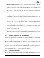
While logically the controller is a single entity, in actuality it is implemented as a set of inter-communicating
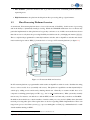
daemons (see figure 3.1; only one module host is shown for simplicity’s sake). The separation of the controller
into a set of daemons allows us to break down its functionality into more manageable pieces that use common
daemon code. Further, this allows for different implementations of the daemons to exist as long as they
comply with a common interface. For instance, the Openflow daemon could have two versions: one for
a Linux-based Openflow switch talking to another daemon on the switch, and another one using NOX to
program a hardware switch using the Openflow protocol.
NETWORK
switch
processing module
procmoduled
resourced
USER INTERFACE
openflowd
monitord
modulehostd
controller host
module host
Figure 3.1: Platform controller architecture overview, only control-plane connections are shown.
The daemons comprising the Flowstream platform’s controller are as follows:
• Resource daemon: This is the controller’s main daemon, providing the interface to the outside world
through which Flowstream users/clients submit allocation requests (as described in the previous chapter).
This daemon takes care of receiving such requests and deciding how to allocate resources to them. It
talks to the module host, processing module and Openflow daemons in order to install these allocations. In addition, it receives both the Openflow statistics from the Openflow daemon and performance
statistics from the module hosts and processing modules via the monitoring daemon. Both of these are
used as input to the resource allocation algorithms.
c CHANGE Consortium 2012
Page 13 of (20)