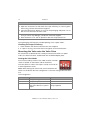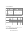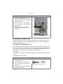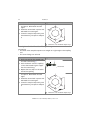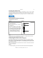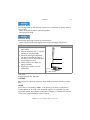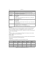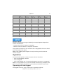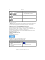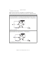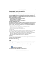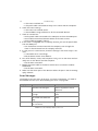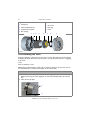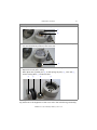
1
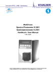
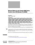
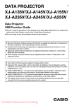
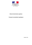
Valve Drive V 2.1S User Manual V6860 HPLC Note: The contents of this user manual apply for the BlueShadow product. Please submit a request on any article numbers for BlueShadow. Table of Contents 3 Table of Contents Note: For your own safety, read the manual and always observe the warnings and safety information on the device and in the manual. Intended Use . . . . . . . . . . . . . . . . . . . . . . . . . . . . . . . . . . . . . . . . . . . . . . . . 6 Device Overview . . . . . . . . . . . . . . . . . . . . . . . . . . . . . . . . . . . . . . . . . . . . 6 Valves and Valve Drives . . . . . . . . . . . . . . . . . . . . . . . . . . . . . . . . . . . . 6 Front View . . . . . . . . . . . . . . . . . . . . . . . . . . . . . . . . . . . . . . . . . . . . . . 7 Rear View . . . . . . . . . . . . . . . . . . . . . . . . . . . . . . . . . . . . . . . . . . . . . . . 7 Valve Types . . . . . . . . . . . . . . . . . . . . . . . . . . . . . . . . . . . . . . . . . . . . . . . . 8 2-Position Valves . . . . . . . . . . . . . . . . . . . . . . . . . . . . . . . . . . . . . . . . . 8 Multiposition Valves . . . . . . . . . . . . . . . . . . . . . . . . . . . . . . . . . . . . . . 9 Valve Drives . . . . . . . . . . . . . . . . . . . . . . . . . . . . . . . . . . . . . . . . . . . . . . 10 Seals . . . . . . . . . . . . . . . . . . . . . . . . . . . . . . . . . . . . . . . . . . . . . . . . . . . . 10 Eluents . . . . . . . . . . . . . . . . . . . . . . . . . . . . . . . . . . . . . . . . . . . . . . . . . . 11 Scope of Delivery . . . . . . . . . . . . . . . . . . . . . . . . . . . . . . . . . . . . . . . . . . . . 12 Safety . . . . . . . . . . . . . . . . . . . . . . . . . . . . . . . . . . . . . . . . . . . . . . . . . . . . . 12 Signal Words . . . . . . . . . . . . . . . . . . . . . . . . . . . . . . . . . . . . . . . . . . . . . . 14 Decontamination . . . . . . . . . . . . . . . . . . . . . . . . . . . . . . . . . . . . . . . . . . 14 Symbols and Signs . . . . . . . . . . . . . . . . . . . . . . . . . . . . . . . . . . . . . . . . . . . 15 Installation . . . . . . . . . . . . . . . . . . . . . . . . . . . . . . . . . . . . . . . . . . . . . . . . . 15 Contact Data . . . . . . . . . . . . . . . . . . . . . . . . . . . . . . . . . . . . . . . . . . . . . 16 Transport . . . . . . . . . . . . . . . . . . . . . . . . . . . . . . . . . . . . . . . . . . . . . . . . 16 Operating Environment . . . . . . . . . . . . . . . . . . . . . . . . . . . . . . . . . . . . . 16 Space Requirements . . . . . . . . . . . . . . . . . . . . . . . . . . . . . . . . . . . . . . 16 Installation Site . . . . . . . . . . . . . . . . . . . . . . . . . . . . . . . . . . . . . . . . . 17 Setup . . . . . . . . . . . . . . . . . . . . . . . . . . . . . . . . . . . . . . . . . . . . . . . . . . . 17 Unpacking . . . . . . . . . . . . . . . . . . . . . . . . . . . . . . . . . . . . . . . . . . . . . 17 Checking the Scope of Delivery . . . . . . . . . . . . . . . . . . . . . . . . . . . . . 18 Mounting the Valve onto the Valve Drive . . . . . . . . . . . . . . . . . . . . . . . . 18 Setting the Valve Mode . . . . . . . . . . . . . . . . . . . . . . . . . . . . . . . . . . . 18 Screwing the Adapter Plate onto the Valve Drive . . . . . . . . . . . . . . . . 19 Screwing the Valve onto the Valve Drive . . . . . . . . . . . . . . . . . . . . . . 20 AZURA V 2.1S User Manual, V6860, Version 2.2 4 Table of Contents Installing the Sample Loop . . . . . . . . . . . . . . . . . . . . . . . . . . . . . . . . . . . 21 Description for PEEK Sample Loop . . . . . . . . . . . . . . . . . . . . . . . . . . . 21 Description for Stainless Steel Sample Loop . . . . . . . . . . . . . . . . . . . . 22 Inserting the Needle Seal . . . . . . . . . . . . . . . . . . . . . . . . . . . . . . . . . . . . 23 Connecting the Device to the Computer . . . . . . . . . . . . . . . . . . . . . . . . 23 Configuring the LAN Settings . . . . . . . . . . . . . . . . . . . . . . . . . . . . . . 24 Connecting the Cables . . . . . . . . . . . . . . . . . . . . . . . . . . . . . . . . . . . . 24 Configuring the Router . . . . . . . . . . . . . . . . . . . . . . . . . . . . . . . . . . . 25 Integrating the LAN into a Company Network . . . . . . . . . . . . . . . . . . 25 Controlling Several Systems Separately in a LAN . . . . . . . . . . . . . . . . 26 Connecting the Remote Connector . . . . . . . . . . . . . . . . . . . . . . . . . . . . . 26 GROUND . . . . . . . . . . . . . . . . . . . . . . . . . . . . . . . . . . . . . . . . . . . . . . . 27 HOME . . . . . . . . . . . . . . . . . . . . . . . . . . . . . . . . . . . . . . . . . . . . . . . . . . 27 BIN 0 - 3 . . . . . . . . . . . . . . . . . . . . . . . . . . . . . . . . . . . . . . . . . . . . . . 28 Binary Code . . . . . . . . . . . . . . . . . . . . . . . . . . . . . . . . . . . . . . . . . . . . 28 Ground . . . . . . . . . . . . . . . . . . . . . . . . . . . . . . . . . . . . . . . . . . . . . . . . . . 29 Operation . . . . . . . . . . . . . . . . . . . . . . . . . . . . . . . . . . . . . . . . . . . . . . . . . . 29 Operating with the Keypad . . . . . . . . . . . . . . . . . . . . . . . . . . . . . . . . . . . 29 Operation with Chromatography Software . . . . . . . . . . . . . . . . . . . . . . . 30 Switch On and Self Test . . . . . . . . . . . . . . . . . . . . . . . . . . . . . . . . . . . . . 30 Setting the Valve Position . . . . . . . . . . . . . . . . . . . . . . . . . . . . . . . . . . . . 31 Injecting the Sample . . . . . . . . . . . . . . . . . . . . . . . . . . . . . . . . . . . . . . . . 31 Application Examples . . . . . . . . . . . . . . . . . . . . . . . . . . . . . . . . . . . . . . . . . 32 Valve Positions . . . . . . . . . . . . . . . . . . . . . . . . . . . . . . . . . . . . . . . . . . . . 32 Valve Position Load (L) . . . . . . . . . . . . . . . . . . . . . . . . . . . . . . . . . . . . . 32 Valve Position Inject (I) . . . . . . . . . . . . . . . . . . . . . . . . . . . . . . . . . . . . . 33 Selecting the Column . . . . . . . . . . . . . . . . . . . . . . . . . . . . . . . . . . . . . . . 34 Backflushing the Column . . . . . . . . . . . . . . . . . . . . . . . . . . . . . . . . . . . . 35 Backflushing the Precolumn . . . . . . . . . . . . . . . . . . . . . . . . . . . . . . . . . . 35 Functional Tests IQ and OQ . . . . . . . . . . . . . . . . . . . . . . . . . . . . . . . . . . . . 37 Troubleshooting . . . . . . . . . . . . . . . . . . . . . . . . . . . . . . . . . . . . . . . . . . . . . 37 LAN . . . . . . . . . . . . . . . . . . . . . . . . . . . . . . . . . . . . . . . . . . . . . . . . . . . . 37 Error Messages . . . . . . . . . . . . . . . . . . . . . . . . . . . . . . . . . . . . . . . . . . . . 38 Maintenance and Care . . . . . . . . . . . . . . . . . . . . . . . . . . . . . . . . . . . . . . . . 39 Cleaning and Caring for the Device . . . . . . . . . . . . . . . . . . . . . . . . . . . . 39 AZURA V 2.1S User Manual, V6860, Version 2.2 Table of Contents 5 Valve Assembly . . . . . . . . . . . . . . . . . . . . . . . . . . . . . . . . . . . . . . . . . . . . 39 Disassembling the Valve . . . . . . . . . . . . . . . . . . . . . . . . . . . . . . . . . . . . . 40 Orientating the Rotor Seal in the Valve . . . . . . . . . . . . . . . . . . . . . . . . . . 42 Technical Data . . . . . . . . . . . . . . . . . . . . . . . . . . . . . . . . . . . . . . . . . . . . . . 42 Repeat Orders . . . . . . . . . . . . . . . . . . . . . . . . . . . . . . . . . . . . . . . . . . . . . . 43 Valve Drive and Accessories . . . . . . . . . . . . . . . . . . . . . . . . . . . . . . . . . . . 43 Valves for Drives . . . . . . . . . . . . . . . . . . . . . . . . . . . . . . . . . . . . . . . . . . . 43 Manual Valves . . . . . . . . . . . . . . . . . . . . . . . . . . . . . . . . . . . . . . . . . . . . . 44 Power Cable . . . . . . . . . . . . . . . . . . . . . . . . . . . . . . . . . . . . . . . . . . . . . . 44 Wear Parts . . . . . . . . . . . . . . . . . . . . . . . . . . . . . . . . . . . . . . . . . . . . . . . 45 Disposal . . . . . . . . . . . . . . . . . . . . . . . . . . . . . . . . . . . . . . . . . . . . . . . . . . . 46 Legal Information . . . . . . . . . . . . . . . . . . . . . . . . . . . . . . . . . . . . . . . . . . . 47 Warranty Conditions . . . . . . . . . . . . . . . . . . . . . . . . . . . . . . . . . . . . . . . . 47 Transport Damage . . . . . . . . . . . . . . . . . . . . . . . . . . . . . . . . . . . . . . . . . 47 Index . . . . . . . . . . . . . . . . . . . . . . . . . . . . . . . . . . . . . . . . . . . . . . . . . . . . . 48 Declaration of Conformity . . . . . . . . . . . . . . . . . . . . . . . . . . . . . . . . . . . . . 50 To whom it may concern In case you prefer a French language user manual for this product, submit your request including the corresponding serial number via email or fax to KNAUER: [email protected] +49 30 8015010 Thank you. A qui que ce soit Si jamais vous préfériez un manuel en francais pour ce poduit contacter KNAUER par email ou par fax avec le no. de série: [email protected] +49 30 8015010 Merci beaucoup. AZURA V 2.1S User Manual, V6860, Version 2.2 6 Intended Use Intended Use Note: Only use the device for applications that fall within the range of the intended use. Otherwise, the protective and safety equipment of the device could fail. Description 2-position valves are used in the HPLC to bring in the sample from the sample loop in the pumps high pressure flow, so that the sample is transported to the column. The sample is brought into the sample loop with a syringe or a feed pump. Multiposition valves serve for fractionating, eluent selection, or sample selection. 2-position valves have 6 ports and 3 channels (6P/3C), multiposition valves have 1 channel always. Operating Ranges Among others, the device can be used for analytical or purification tasks. Device Overview Various types of valves with different operating modes allow the use of these valves for a variety of applications. It is important that valve drive and valve are compatible. You can mount additional manual valves to an optional mounting bracket that can be fixed with screws on the AZURA modules or other devices. Find further information on our website www.knauer.net. Valves and Valve Drives Valves and valve drives are completely assembled and tested when they leave the factory. Legend 1 valve drive with valve 2 valve for drive 3 manual valve 1 2 3 Fig. 1 overview of valves and valve drives AZURA V 2.1S User Manual, V6860, Version 2.2 Intended Use 7 Front View The valve drive has a display and a keypad. Legend 1 multifunction key [L] [>] 2 multifunction key [I] [<] 3 position indicator 1 2 4 adapter plate 5 valve for drive 6 bore holes for mounting bracket 3 4 5 6 Fig. 2 valve drive with 2-position valve Rear View On the rear of the device there are the power-connection bushing, ground for grounding the device, connections for external devices, symbols, warning signs and serial number. External devices can be connected to the valve drive in three different ways: via remote connector via LAN connector within a network via RS-232 port AZURA V 2.1S User Manual, V6860, Version 2.2 8 Legend 1 serial number 2 RS-232 port 3 LAN connector Intended Use 4 remote connector 5 mains power connection 6 hole for the ground connection 1 2 3 4 5 6 7 Fig. 3 valve drive Valve Types Generally, valves can be operated manually through a lever or electrically through the valve drive. Valves are available as 2-position valves or multiposition valves Ports and channels are described by abbreviations to enable the identification of a specific valve. Example: 6P/3C = 2-position valve with 6 ports and 3 channels. In case of the multiposition valves, the input/output port is not counted. Valves are available in stainless steel or PEEK and with 1/8¨ or 1/16¨ connectors. 2-Position Valves 2-position valves are used for injection, column switching, or column backflushing. In case of the 2-position valves, the rotary motions of the electrical valve are limited to 2 positions with a rotation angle of 60°. You control 2-position valves either manually through a lever or electrically through the valve drive. AZURA V 2.1S User Manual, V6860, Version 2.2 Intended Use 9 Legend 2 port number 1 adapter plate for mounting on the 3 channel valve drive 2 1 3 1 6 2 5 3 4 Fig. 4 scheme of a 2-position valve Reed Contact The reed contact inside the 2-position valve causes a short-circuit contact. This short-circuit contact can be used as a start signal for the entire analytical system or as a start signal for a measurement with the detector. The function is to be set on the receiving device. Multiposition Valves Multiposition valves are used to switch fluid streams, e.g. the selection of eluents, columns or for fractionating of eluate. Multiposition valves are employed for fractioning if the form and the size of the fraction containers should be freely selectable. By combining up to 8 multiposition valves, up to 120 positions can be used for fractioning in applications in the preparative HPLC. You control all multiposition valves electrically through a valve drive. 6P-multiposition valves can alternatively be controlled manually through a lever. AZURA V 2.1S User Manual, V6860, Version 2.2 10 Intended Use Legend 1 port number 2 connection between central port and ports 1-6 3 adapter plate for mounting on the valve drive 3 2 1 Fig. 5 scheme of a 6P-multiposition valve Valve Drives Valve drives are operated by a 24 V direct current motor. The valve drive and the valve come factory-set. You can change the valve mode by using the DIP switches (Dual-Inline Package) on the bottom of the device. By means of chromatography software or a cable for remote control, certain ports can be controlled directly on a valve. switch duration of the valve: 150 ms There is a matching valve drive for every valve type. 6P/3C valves and 6P-multiposition valves operate on the same valve drive. Note: Submit any questions about the possible combinations between valves and valve drives to the Technical Support of KNAUER. All valve drives come with a ready-mounted valve (see “Repeat Orders” on page 43). Seals You are to use the seals according to their pressure resistance. For pressures < 50 bar you can use a bicone seal. For pressures > 50 bar you use Dynaseal for PEEK capillaries and screw fittings with ferrules for stainless steel or titanium capillaries. AZURA V 2.1S User Manual, V6860, Version 2.2 Intended Use Legend 1 biconical seal 2 1 11 2 Dynaseal 3 screw fitting with ferrule 3 Fig. 6 seals Eluents Chemical resistance of a valve depends on the stator material and the rotor seal. Even small quantities of other substances, such as additives, modifiers, or salts can influence the durability of the materials. Note: The list of selected solvents was compiled based on research in the pertinent literature and is only a recommendation. If there is any doubt, contact the Technical Support. Material pH range Suitable Eluents Less Suitable Elu- Unsuitable Eluents ents POM-H-TF acetone acetonitrile pH 3-14 PPS HPV ethanol ethylacetate hexane heptane isopropanol methanol acetone dichloromethane ethanol ethylacetate hexane heptane isopropanol methanol 1 M NaOH 50 mM KH2PO4 acetonitrile strong bases oxydizing acids AZURA V 2.1S User Manual, V6860, Version 2.2 dichloromethane 12 Scope of Delivery Material pH range Suitable Eluents Vespel acetone acetonitrile ethanol ethylacetate hexane heptane isopropanol methanol 50 mM KH2PO4 acetonitrile ethanol ethylacetate hexane heptane isopropanol methanol pH 0-10 Tefzel pH 0-14 Less Suitable Elu- Unsuitable Eluents ents dichloromethane acetone Scope of Delivery Note: Only use original parts and accessories made by KNAUER or a company authorized by KNAUER. V 2.1S valve + valve drive power adapter 24 V; max. 55 W + power cable user manual DE/EN Installation Qualification AZURA accessories kit Safety Professional Group The user manual addresses persons who are qualified as chemical laboratory technicians or have completed comparable vocational training. The following knowledge is required: Fundamental knowledge of liquid chromatography Knowledge regarding substances that are suitable only to a limited extent for use in liquid chromatography Knowledge regarding the health risks of chemicals AZURA V 2.1S User Manual, V6860, Version 2.2 Safety 13 Participation during an installation of a device or a training by the company KNAUER or an authorized company. If you do not belong to this or a comparable professional group, you may not perform the work described in this user manual under any circumstances. In this case, please contact your superior. Safety Equipment When working with the device, take measures according to lab regulations and wear protective clothing: Safety glasses with side protection Protective gloves Lab coat What must be taken into account? All safety instructions in the user manual The environmental, installation, and connection specifications in the user manual National and international regulations pertaining to laboratory work Original spare parts, tools, and solvents made or recommended by KNAUER Good Laboratory Practice (GLP) Accident prevention regulations published by the accident insurance companies for laboratory work Filtration of substances under analysis Use of inline filters Once they have been used, never re-use capillaries in other areas of the HPLC system. Only use a given PEEK fitting for one specific port and never re-use it for other ports. Always install new PEEK fittings on each separate port. Follow KNAUER or manufacturer's instructions on caring for the columns More safety-relevant information is listed below: flammability: Organic solvents are highly flammable. Since capillaries can detach from their screw fittings and allow solvent to escape, it is prohibited to have any open flames near the analytical system. solvent tray: Risk of electrical shock or short circuit if liquids get into the device's interior. For this reason, place all bottles in a solvent tray. solvent lines: Install capillaries and tubing in such a way that liquids cannot get into the interior in case of a leak. leaks: Regularly check if any system components are leaking. power cable: Defective power cables are not to be used to connect the device and the power supply system. AZURA V 2.1S User Manual, V6860, Version 2.2 14 Safety self-ignition point: Only use eluents that have a self-ignition point higher than 150 °C under normal ambient conditions. power strip: If several devices are connected to one power strip, always consider the maximum power consumption of each device. power supply: Only connect devices to voltage sources, whose voltage equals the device's voltage. toxicity: Organic eluents are toxic above a certain concentration. Ensure that work areas are always well-ventilated! Wear protective gloves and safety glasses when working on the device! Where is use of the device prohibited? Never use the system in potentially explosive atmospheres without appropriate protective equipment. For further information, contact the Technical Support of KNAUER. Decommissioning the Device Securely At any time, take the device completely out of operation by either switching off the power switch or by pulling the power plug. Opening the Device The device may be opened by the KNAUER Technical Support or any company authorized by KNAUER only. Signal Words Possible dangers related to the device are divided into personal and material damage in this user manual. Lethal injuries will occur. Serious or moderate injuries can occur. Minor injuries can occur. Device defects can occur. Decontamination Contamination of devices with toxic, infectious or radioactive substances poses a hazard for all persons during operation, repair, sale, and disposal of a device. AZURA V 2.1S User Manual, V6860, Version 2.2 Symbols and Signs 15 Life-threatening injuries Health danger if getting in contact with toxic, infectious or radio-active substances. Before disposing of the device or sending it away for repair, you are required to decontaminate the device in a technically correct manner. All contaminated devices must be properly decontaminated by a specialist company or the operating company before they can be recommissioned, repaired, sold, or disposed of. All materials or fluids used for decontamination must be collected separately and disposed of properly. Symbols and Signs The following symbols and signs can be found on the device, in the chromatography software or in the user manual: Symbol Meaning Electric shock hazard Electrostatic discharge hazard, damages to system, device, or components can occur. A device or system marked with CE fulfills the product specific requirements of European directives. This is confirmed in a Declaration of Conformity. Testing seals in Canada and the USA at nationally recognized testing centers (NRTL). The certified device or system has successfully passed the quality and security tests. Installation This chapter describes all preparatory steps prior to the start-up. If you encounter difficulties during installation, contact the Technical Support. AZURA V 2.1S User Manual, V6860, Version 2.2 16 Installation Contact Data Phone +49 30 809727-111 Fax +49 30 8015010 E-mail [email protected] Transport Carefully prepare the device for transport or storage. If you want to return your device to KNAUER for repairs, enclose the Service Request Form which can be downloaded from our website. Device Data For a secure transport, note the weight and dimensions of the device (see Technical Data). Bruises Damage to the device by carrying or lifting it on protruding housing parts. The device may fall and thus cause injuries. Lift the device on the side of the housing only. Lifiting Clasp the device at its side panels and lift it out of the packaging. Do not hold onto front cover or leak tray. Operating Environment Only if the requirements for ambient conditions of the operating environment are met, can the intended use be ensured. You will find the ambient conditions under Technical Data and below. Device defect The device overheats at exposure to sunlight and insufficient air circulation. Device failures are very likely. Set up the device in such a way that it is protected against exposure to direct sunlight. Keep at least 15 cm clear at the rear and 5–10 cm at each side for air circulation. Space Requirements Position the device on a level and even surface. AZURA V 2.1S User Manual, V6860, Version 2.2 Installation 17 Protect the device against direct exposure to sunlight. Set up the device at a location not exposed to air drafts (A/C systems). Do not set up the device in the vicinity of other machines that cause floor vibrations. Lateral distance to other devices: At least 5 cm if another device is set up on one side At least 10 cm if further devices are set up on both sides Leave the power plug on the rear of the device accessible to be able to disconnect the device from the mains. Installation Site air humidity: below 90 % (non-condensing) temperature range: 4–40 °C; 39.2–104 °F Setup Prior to setting up the device, find a suitable place according to the requirements and remove the packaging.. The setup requirements and a description can be found in the following section. Unpacking Prerequisites Check packaging for damage caused during transportation. Tools utility knife Bruises Damage to the device by carrying or lifting it on protruding housing parts. The device may fall and thus cause injuries. Lift the device on the side of the housing only. Process 1. Set-up the package in such a way that you can read the label. 2. Using the utility knife, cut the adhesive tape and open the packaging. AZURA V 2.1S User Manual, V6860, Version 2.2 18 Installation Process 3. Remove the foam insert. Take out the accessories kit and the manual. 4. Open the accessories kit and check the scope of delivery. In case any parts are missing, contact the Technical Support. 5. Clasp the device from below, lift it out of the packaging and place it on its feet. Do not hold onto the front cover. 6. Check the device for signs of damage that occurred during transport. In case you notice any damage, contact the Technical Support. 7. Place the device in its side of operation. Remove the protective foil. Next Steps Store packaging and keep the included packing list for repeat orders. Checking the Scope of Delivery 1. Check whether the device and accessories are complete. 2. If a part is missing, inform the technical support of the manufacturer. Mounting the Valve onto the Valve Drive All valve drives are delivered with a ready-mounted valve head. For repeat orders, the electrical valves are delivered with included adapter plate. Setting the Valve Mode You set the mode by means of the 4 DIP switches. The DIP switch is located on the bottom side of the device. The valve drive for valves with 6 ports can be set for 6P/3C or 6P-multiposition valves. Note: While setting the valve mode, switch the device off. Switch on the device after the configuration so that the changes become effective. Switch Assignment DIP Function Comment 1 specify valve type - 2 specify valve position - 3 and 4 set the port OUT/BIN 3 on the set DIP switches 3 and 4 back of the device as input or always opposite output AZURA V 2.1S User Manual, V6860, Version 2.2 Installation 19 Basic Functions of the DIP Switches DIP I/0 S6 S12 S16 1 ON 6P-multiposition valve 12P-multiposition valve not permitted OFF 6P/3C not permitted 16P-multiposition valve ON BIN 0-2 at 6P-multi- BIN 0-3 position valves BIN 0-3 OFF RS-232, manual, Pos. 1; [I]; [L] RS-232, manual, Pos. 1; [I]; [L] RS-232, manual, Pos. 1; [I]; [L] 3 ON output OUT/BIN 3 output OUT/BIN 3 output OUT/BIN 3 4 OFF 3 OFF not permitted input OUT/BIN 3 input OUT/BIN 3 4 ON 2 Combination Possibilities per Valve Type Drive Valve Mode DIP1 DIP2 DIP3 DIP4 V6 6P/3C analog/RS-232 OFF OFF ON OFF 6P-multiposi- analog/RS-232 tion valve ON OFF ON OFF 6P-multiposi- binary tion valve ON ON ON OFF 12P-multiposition valve analog/RS-232 ON OFF ON OFF 12P-multiposition valve binary ON ON OFF ON 16P-multiposition valve analog/RS-232 OFF OFF ON OFF 16P-multiposition valve binary OFF ON OFF ON V12 V16 Screwing the Adapter Plate onto the Valve Drive Tools Phillips screwdriver, size 3 1. Attach the adapter plate the right way around. The openings for the screws point to the front. 2. Using the screwdriver, screw on the 2 screws (M3). AZURA V 2.1S User Manual, V6860, Version 2.2 20 Installation Legend 1 2 3 4 5 6 rear side of a valve drive 1 2 markings for the mounting opening for the drive axle 3 adapter plate for the mounting opening for countersunk screws 4 Phillips-head screws 5 6 Fig. 7 rear side of valve drive Screwing the Valve onto the Valve Drive Prerequisites The DIP switch was set correctly. The valve drive matches the number of the valve ports. Tools Allen wrench, size 3 Device defect Device damage due to blocked eluent flow. Check that the number of valve ports is identical with the type of valve drive (6V, 12V, 16V). Note: The sample loop is not included with the delivery. AZURA V 2.1S User Manual, V6860, Version 2.2 Installation Process 21 Figure 1. Switch the valve drive 1 on. The initialization of the valve drive causes the markings on the drive axle to be on top. 1 2 2. Push the valve 3 onto the drive axle 2. The port 1 of the valve has to point up. 3. Using the wrench, screw the adapter plate to the valve drive (screws 4). 3 4 Fig. 8 mounting the valve onto the valve drive Installing the Sample Loop To install the sample loop, you have to select the right fittings and seals (see “Seals” on page 10). There are separate descriptions on how to install PEEK or stainless steel sample loops. Description for PEEK Sample Loop You find either shorter and longer or only longer fittings inside the accessories kit. Please note that you should always use a long fitting for the syringe port. In conclusion, you install the sample loop with long fittings on both ends or with a short fitting on one end and a long fitting on the other end. Prerequisites The ends of the sample loop were cut straight at a right angle to the capillary axis. The Dynaseals are at hand. Process Figure 1. Insert one end of the sample loop into the fitting. 2. Firstly push the clamping ring 1 onto the capillary, secondly the seal ring 2. 3. Repeat the first steps on the other end of the capillary. 1 2 3 Fig. 9 Dynaseal: fitting and seal AZURA V 2.1S User Manual, V6860, Version 2.2 22 Installation Process Figure 4. Fixate the first seal by screwing it into port 2. Afterwards unscrew again. 5. Fixate the second seal in port 5 and afterwards unscrew again. 6. Screw the sample loop evenly and simultaneously into port 2 and port 5. 1 6 2 5 3 4 Fig. 10 scheme of an installed sample loop Description for Stainless Steel Sample Loop Prerequisites The ends of the sample loop were cut straight at a right angle to the capillary axis. The screw fittings are at hand. Process Figure 1. Insert one end of the sample loop into the screw fitting 1. 2. Push the ferrule onto the capillary so that the broader sight is opposite the screw fitting. 3. Repeat the first steps on the other end of the capillary. 4. Fixate the first seal by screwing it into port 2. Afterwards unscrew again. 5. Fixate the second seal in port 5 and afterwards unscrew again. 6. Screw the sample loop evenly and simultaneously into port 2 and port 5. 2 1 Fig. 11 screw fitting and ferrule 1 6 2 5 3 4 Fig. 12 scheme of an installed sample loop AZURA V 2.1S User Manual, V6860, Version 2.2 Installation 23 Inserting the Needle Seal You fill the sample loop with a syringe or a feed pump. To do so, insert a needle seal into the syringe connection and fixate it with a biconical seal (see “Seals” on page 10). The needle seal for the syringe connection is available as PTFE or Teflon tube. Component defect Rotor-seal damage caused from non-fitting seal. Only reuse seals in one and the same location. Preferably use a new seal. Process Figure 1. Insert the needle seal 1 into the Dynaseal fitting2. 1 2. Put the biconical seal 3 onto the needle seal. 3. Guide the needle into the needle seal , so that both ends fit equally. 4. Insert the needle seal and needle into the port 1 and screw in manually. The Dynasel fitting sits adequately tight when you feel a resistance at pulling the needle. 2 3 Fig. 13 scheme of syringe port Result The 2-position valve is prepared for the injection of sample solution into the sample loop via a glass syringe with luer lock. Connecting the Device to the Computer This section describes how to set up an HPLC system in a local area network (LAN) and how a network administrator can integrate this LAN into your company network. The description applies to the operating system Windows® and all conventional routers. Note: To set up a LAN, we recommend to use a router. That means the following steps are required: Process 1. On the computer, go to the control panel and check the LAN properties. AZURA V 2.1S User Manual, V6860, Version 2.2 24 2. 3. 4. 5. Installation Hook up the router to the devices and the computer. On the computer, configure the router to set up the network. Install the chromatography software from the data storage device. Switch on the device and run the chromatography software. Configuring the LAN Settings The LAN uses only one server (which is normally the router) from that the devices automatically receive their IP address. Prerequisite In Windows®, power saving, hibernation, standby, and screen saver must be deactived. In case you use an USB-to-COM box, the option "Allow the computer to turn off ths device to save power" in the devicemanager must be deactivated for all USB hosts. Only for Windows 7: For the network adapter, the option "Allow the computer to turn off this device to save power" in the Device Manager must be deactivated. Process 1. In Windows 7 choose Start Control Panel Network and Sharing Center. 2. Double-click on LAN Connection. 3. Click on the button Properties. 4. Select Internet Protocol version 4 (TCP/IPv4). 5. Click on the button Properties. 6. Check the settings in the tab General. The correct settings for the DHCP client are: a) Obtain IP address automatically b) Obtain DNS server address automatically 7. Click on the button OK. Connecting the Cables A router 3 has several LAN ports 2 and one WAN port 4 that can be used to integrate the LAN into a wide area network (WAN), e.g. a company network or the Internet. In contrast, the LAN ports serve to set up a network from devices 1 and a computer 5. To avoid interference, we recommend operating the HPLC system separately from the company network. AZURA V 2.1S User Manual, V6860, Version 2.2 Installation 1 3 2 4 25 5 You will find patch cables for each device and the router in the accessories kit. To connect the router to a WAN, an additional patch cable is required, which is not supplied within the scope of delivery. Prerequisite The computer has been switched off. There is a patch cable for each device and the computer. Process 1. Use the patch cable to connect the router and the computer. Repeat this step to connect all devices. 2. Use the power supply to connect the router to the mains power system. Configuring the Router The router is preset at the factory. You will find a label at the bottom side of the router, on which IP address, user name, and password are printed. These information help to open the router configuration. Process 1. To open the router configuration, start your Internet browser and enter the IP address (not for all routers). 2. Enter user name and password. 3. Configure the router as DHCP server. 4. In the router configuration, check the IP address range and make changes if necessary. Result Once the router has assigned IP addresses to all devices, the chromatography software can be used to remotely control the system. Integrating the LAN into a Company Network A network administrator can integrate the LAN into your company network. In this case you use the WAN port of the router. AZURA V 2.1S User Manual, V6860, Version 2.2 26 Installation Prerequisite There is a patch cable for the connection. Process 1. Check that the IP address range of the router and of the company network do not overlap. 2. In case of an overlap, change the IP address range of the router. 3. Use the patch cable to connect the router WAN port to the company network. 4. Restart all devices, including the computer. Controlling Several Systems Separately in a LAN Devices connected to a LAN communicate through ports, which are part of the IP address. If more than one HPLC system is connected to the same LAN and you plan on controlling them separately, you can use different ports to avoid interference. Therefore, the port number for each device must be changed and this same number must be entered into the device configuration of the chromatography software. We recommend to use the same port number for all devices in the same system. Note: The port is set to 10001 at the factory. You must use the same numbers in the device configuration of the chromatography software as in the device, otherwise the connection fails. Process 1. Find out port number and change it on the device. 2. Enter the port number in the chromatography software. Result The connection is established. Connecting the Remote Connector To control one device through another, you use the remote connector. The single ports are used to exchange control signals. You find explanations on the connector assignment at the end of the procedure. To use remote control, you have to connect cables to the pin header. Finally connect the pins of the pin header to the spring contact of the spring strip, which is a connection to the board. Prerequisites The device has been switched off. The power plug has been pulled. Tools depressor tool AZURA V 2.1S User Manual, V6860, Version 2.2 Installation 27 Electronic defect Connecting cables to the multi-pin connector of a switched on device causes a short circuit. Turn off the device before connecting cables. Pull the power plug. Electronic defect Electrostatic discharge can destroy the electronics. Wear a protective bracelet against electrostatic discharge and ground. Process Figure 1. Place the pin header 3 on a suitable surface. 2. Push the depressor tool 1 into the opening on the pin header. 3. Continue pushing the depressor tool down and lead the cable 2 into the front end. Afterwards pull out the depressor tool. 4. Check whether the cables are tightly attached. 5. Plug the pin header onto the spring strip. 1 2 3 Fig. 14 pin header Next Steps Bring the device into operation. GROUND Start and error signals are started to the ground connection without a current flow. HOME If the valve is controlled by HOME , it has priority over control via RS-232 or manual operation. As long as the switch-off signal is not canceled, the valve cannot be started. The indicator of the position flashes to indicate that the start of the valve is prevented by an external signal. AZURA V 2.1S User Manual, V6860, Version 2.2 28 Installation Signal Explanation GROUND Ground connection for start and error signals HOME/POS. 1 Connection for short circuit for creating a switch signal: Valve drive is set to position 1. FORWARD/ LOADING Connection for short circuit for creating a switch signal, example for output: LOADING Move to the next higher port of the valve, e. g. from position 2 to position 3 BACKWARD/ INJECTING Connection for short circuit for creating a switch signal, example for output: INJECTING Move to the next lower port of the valve, e. g. from position 6 to position 5 OUT Connection for short circuit (no current) INJECTING, port 1, low-impedance LOADING, port 2-6 or 2-16, high-impedance BIN 0 - 3 If the DIP switches were set to binary operation, then the connections BIN 0 BIN 2 are available as inputs. The output BIN 3 is active for the ports 1-6. On the 12 port and 16 port valves, BIN 3 is defined as an input so that the ports 9-12 or 9-16 can be used. Note The binary input is inactive during the change of the valve port. This can be used to control further external devices. Binary Code A binary code is entered during binary control so that the valve can be set externally in the correct position (nominal position). Prerequisites The DIP switch of the device was set for the binary control. . Position BIN 0 BIN 1 BIN 2 BIN 3 (20=1) (21=2) (22=4) (23=8) Result, binary 1 0 0 0 0 0 2 1 0 0 0 1 3 0 1 0 0 2 4 1 1 0 0 3 AZURA V 2.1S User Manual, V6860, Version 2.2 Operation Position 29 BIN 0 BIN 1 BIN 2 BIN 3 (20=1) (21=2) (22=4) (23=8) Result, binary 5 0 0 1 0 4 6 1 0 1 0 5 7 0 1 1 0 6 8 1 1 1 0 7 9 0 0 0 1 8 10 1 0 0 1 9 11 0 1 0 1 10 12 1 1 0 1 11 13 0 0 1 1 12 14 1 0 1 1 13 15 0 1 1 1 14 16 1 1 1 1 15 Ground Electronic defect Electronic hazard when using an identically constructed power adapter from another manufacturer. Contact the Technical Support of KNAUER. Never connect the device to the power connection. The ground connection for the valve drive has a designated hole with a thread M3 on the back of the device. Note: If the supplied power adapter is used, then the ground connection remains unused. Operation You have several options to select one port with the valve drive: with chromatography software with the keypad with the Pin Header (see “Connecting the Remote Connector” on page 26) Note: It is not possible to use 2 control methods simultaneously. Example: If the device is connected to the software, it cannot be controlled via Control Unit. Operating with the Keypad The keypad consists of 2 keys, which allow to operate the device. AZURA V 2.1S User Manual, V6860, Version 2.2 30 Operation Figure Function setting the values scrolling through the menu injecting sample loading sample Operation Arrow Keys 1. Hold down the left arrow key. Scroll through the menu using the right arrow key. 2. Let go of the left arrow key and, using both arrow keys, set the values. Operation with Chromatography Software To operate the device with software, you have to establish a connection between the LAN port and a computer. The devices are controlled with e. g. OpenLAB EZChrom edition, ChromGater or ClarityChrom. You find a detailed description on the chromatography software in the corresponding user manual. Switch On and Self Test Prerequisites Valve drive has been set up. Device defect Damage to the rotor seal located inside the valve. Never start or operate the valve without fluid. Process Figure 1. Connect the valve drive with the plug from the external power adapter. 2. Wait until the self test has been completed. 1 Fig. 15 display injection port AZURA V 2.1S User Manual, V6860, Version 2.2 Operation 31 Result After switching on the device, 18 is displayed on the display and the automatic self-test starts. After all tests have been successfully completed, 1 is displayed. Next Steps Set the valve position. Setting the Valve Position The multiposition valves have an internal forwarding function, e.g. from position 6 directly to position 1. Their switching radius is 360°, therefore they can be switched to any desired position by means of the arrow keys. The last setting is inherited. If several valves are switched in series, then all positions will be changed. Note: The valve position can be changed during operation. The change takes effect immediately. Process Figure 1. Use the arrow keys to set a value for the position. 2. Let go of the arrow key. 16 Fig. 16 possible display for V16 Next Steps Start the sample injection. Injecting the Sample Prerequisites The sample loop is mounted between the position 2 and 5 (see “Installing the Sample Loop” on page 21). The syringe port was mounted. The data acquisition was started. Component defect Valve damage when using pointed injection syringes. Use only injection syringes with luer lock and flat-ground cannula. Process Figure 1. Press [L]. Fig. 17 display load AZURA V 2.1S User Manual, V6860, Version 2.2 32 Application Examples Process Figure 2. Fill the injection syringe 3 with eluent. Make sure that there are no air bubbles. 3. Insert the injection syringe into the syringe port 2. 4. Fill the sample loop 1. Leave the syringe connected. 1 2 3 Fig. 18 injection syringe 5. Press [L]. Fig. 19 display inject Result The sample is injected and measured. The syringe remains connected until the next injection. Application Examples This chapter describes possible applications for the different valve types. Of course there are also other applications possible which are not listed here. Valve Positions The eluent flows through the sample loop in opposite direction of the position load (see arrows in the figures). 1. The sample loop is filled by injecting the sample at port 1. The sample runs into the sample loop (port 2 and 5) and excessive sample is transported into the waste container through port 6. 2. The valve is switched from load to inject. 3. The pump (port 4) transports the sample to the column (port 3). 4. The eluent flows through the sample loop in opposite direction then during injection, see arrows in the figures. Valve Position Load (L) In the valve position load the sample is filled into the sample loop. AZURA V 2.1S User Manual, V6860, Version 2.2 Application Examples 33 Legend port 1: sample injection port 4: pump port 2: sample loop port 5: sample loop port 3: column port 6: waste 1 6 2 5 3 4 Fig. 20 valve position load Valve Position Inject (I) In the valve position inject the sample is transported to the column for separation. Legend port 1: sample injection port 4: pump port 2: sample loop port 5: sample loop port 3: column port 6: waste 1 6 2 5 3 4 Fig. 21 valve position inject AZURA V 2.1S User Manual, V6860, Version 2.2 34 Application Examples Reed contact The reed contact informs the analytical system whether the valve is positioned to ‘LOAD’ or ‘INJECT’. Selecting the Column The column selection is used in chromatography, for example, in the following cases: Method development Usage of different columns in the same HPLC system Separation of the sample on the precolumn Separation of the sample components on different columns Note: Make sure there is no pressure when switching between the columns so that the columns are not damaged. Functional Principle From the valve, the sample is transported through the channel 2->1 onto the column A 1. From port 5, the components of the sample are forwarded separately to the detector 2. 2 1 5 6 1 4 3 3 2 Fig. 22 column selection using column A After switching the 2-position valve, the sample is transported through the channel 2->3 to the column B 3. From port 5, the components of the sample are forwarded separately to the detector 2. 2 1 5 6 4 3 1 3 2 Fig. 23 column selection using column B AZURA V 2.1S User Manual, V6860, Version 2.2 Application Examples 35 Backflushing the Column The backflushing of a column is used, for example, in the following cases: analysis of heavily retarding substances optimization of analysis times flushing of a column Note: The eluent flushes the column after switchover in opposite direction. Make sure there is no pressure when switching so that the column is not damaged. Functional Principle From the valve, the column 1 is filled with sample through the channel 2->3. The quicker part of the substances is separated through the channels 6->1 and 5->4 and transported to the detector 2. 5 2 1 6 4 1 3 2 Fig. 24 backflushing - transport of the sample onto the column After switching over the valve, heavily retarding substances are eluted in opposite direction from the column and are transported back to the detector 2. 5 6 4 2 1 3 2 1 Fig. 25 backflushing of the column Backflushing the Precolumn The precolumn is used in chromatography, for example, in the following cases: preseparation or separation of heavily retarding substances AZURA V 2.1S User Manual, V6860, Version 2.2 36 Application Examples protection of the column Note: Precolumn and column are aligned in a row behind each other. Note: The eluent flushes the precolumn after switchover in opposite direction. Functional principle From the valve, the precolumn 1 is filled with sample through the channel 2>3. From the channel 6->1, the quickly dissolved substances on the column 2 are separated while the heavily retarding substances remain in the precolumn. 2 5 6 1 4 3 2 1 Fig. 26 use of precolumn After switching over the valve , the late eluting substances are flushed back in opposite direction from the precolumn 1 to the detector 3. 2 5 3 6 1 4 3 2 1 Fig. 27 backflushing of the precolumn AZURA V 2.1S User Manual, V6860, Version 2.2 Functional Tests IQ and OQ 37 Functional Tests IQ and OQ Installation Qualification (IQ) The customer may request the Installation Qualification, which is free of charge. In case of a request, the Technical Support of KNAUER or from a provider authorized by KNAUER performs this functionality test during the installation. The Installation Qualification is a standardized document that comes as part of the delivery and includes the following: confirmation of flawless condition at delivery check if the delivery is complete certification on the functionality of the device Operation Qualification (OQ) The Operation Qualification includes an extensive functionality test and must be purchased from the manufacturer. Contact the KNAUER Sales Department to request an offer. The Operation Qualification is a standardized KNAUER document and includes the following: definition of customer requirements and acceptance terms documentation on device specifications device functionality check at installation site Test Intervals To make sure that the device operates within the specified range, you should test the device using the Operation Qualification at following intervals: Every 3 months: average useful life of more than 5 days/week or 24 hours/ day; when operating with buffer solutions or other salt solutions: Every 6 months: average useful life of 1 to 5 days/week Execution The test can be carried out either by the Technical Support of KNAUER or from a provider authorized by KNAUER. Troubleshooting LAN Go through the following steps, in case no connection between the computer and the devices can be established. Check after each step if the problem is solved. If the problem cannot be located, call the Technical Support. 1. Check the status of the LAN connection in the Windows task bar: Connected Connection not established If no connection was established, test the following: AZURA V 2.1S User Manual, V6860, Version 2.2 38 2. 3. 4. 5. 6. 7. 8. Troubleshooting Is the router switched on? Is the patch cable connected correctly to the router and the computer? Check the router settings: Is the router set to DCHP server? Is the IP address range sufficient for all the connected devices? Check all connections: Are the patch cable connected to the LAN ports and not the WAN port? Are all cable connections between devices and router correct? Are the cables plugged in tightly? If the router is integrated into a company network, pull out the patch cable from the WAN port. Can the devices communicate with the computer, even though the router is disconnected from the company network? In case you own a Control Unit, check the settings in the menu Setup > Network. Is LAN-DHCP set for controlling? Did the device receive an IP address? Turn off all devices, router, and computer. Firstly, turn on the router and secondly turn on the devices and the computer. Has this been successful? Replace the patch cable to the device with that no connection could be established. Has this been successful? Make sure that the IP port of the device matches the port in the chromatography software. Error Messages The display shows the status of the error. To renew components, you need to disassemble the valve (see “Disassembling the Valve” on page 40). Display Cause Of the Fault Solution E0 Setting the position of the valve was not changed. Replace the rotor seals of the valve or replace the motor drive unit. E1 Value of the motor current is too high. Replace the rotor seals of the valve. E2 Change from one valve position to the next takes too long. Replace the rotor seals of the valve. E3 Switch position of DIP 3 and 4 Correct DIP switch 3 and 4. are not correct. AZURA V 2.1S User Manual, V6860, Version 2.2 Maintenance and Care Display Cause Of the Fault Solution E4 Valve position 1 is not recognized. Readjust sensor board. E5 Switch position of DIP 1 and 2 Correct DIP switch 1 and 2. are not correct. E6 39 Binary code is not correct. Check if valve setting (DIP switches) is correct,, then send the correct position parameter (binary code). Memory error Switch the device off and on again. Note: If it is not possible to rectify the fault based on this list, then contact the Technical Support. Maintenance and Care Cleaning and Caring for the Device Device defect Intruding liquids can cause damage to the device. Place solvent bottles next to the device or in a solvent tray. Moisten the cleaning cloth only slightly. All smooth surfaces of the device can be cleaned with a mild, commercially available cleaning solution, or with isopropanol. Valve Assembly The valve contains a rotor in its housing. With disk springs, the rotor creates a certain pressure stability. AZURA V 2.1S User Manual, V6860, Version 2.2 40 Maintenance and Care Legend 1 2 3 4 5 6 7 8 axial plate axial needle bearing compensation plate rotor rotor seal seal ring stator disk spring 5 1 23 4 6 7 8 Fig. 28 exploded view of a valve Disassembling the Valve During assembly, make sure the rotor seal is in the right position and installed properly, because otherwise there may be a mix-up of the channels or clogging may occur. Tools Allen screwdriver, size 3 Note: During disassembly, make sure to mark the position of the rotor seal on the cylinder pins to make the assembly of the valve easier. Procedure 1. Loosen the 3 screws 1 of the valve alternatingly with a screwdriver (M3). Hold the housing of valve together so that the individual parts do not fall out. 2. Take off the top part. 1 2 AZURA V 2.1S User Manual, V6860, Version 2.2 Maintenance and Care 41 Procedure 3. The cylinder pins 3 and the rotor seal 4become visible. 3 4 4. Remove the rotor seal 5and deposit in the correct orientation. Mark position and installation position of the rotor seal. 5 5. Hold the inner components and turn over the bottom part in order to deposit the inner parts orderly. Rotor plate with cylinder pins 6, 4 disk springs (2 pairs) 7, rotor seal 8, several sealing disks 9 inside the valve. 6 7 8 9 Next Steps Pay attention to the alignment of the rotor seal in the valve during reassembly. AZURA V 2.1S User Manual, V6860, Version 2.2 42 Technical Data Orientating the Rotor Seal in the Valve Valve Type Position Of Rotor Seal During Installation multiposition valve 1 rotor 1 2 3 4 2 marking 3 cylinder pins 4 rotor with seal Fig. 29 multiposition valve: position of the rotor seal 2-position valves Fig. 30 2-position valve: position of the rotor seal Technical Data Ambient Conditions temperature range 4 – 40 ˚C; 39.2 – 104 ˚F air humidity below 90 % humidity (non-condensing) height above sea level maximum 2000 meters Valve Drive control LAN, RS-232, keypad dimensions 105 x 100 x 185 mm (width x height x depth) weight 1.86 kg display LCD power supply power adapter 24 V DC, 60 W Valve for Valve Drive fitting PEEK 10/32; 1/16¨ DYNASEAL; 1/16¨; 1/8¨ switch duration of the valve approx. 300 ms; via reed contact AZURA V 2.1S User Manual, V6860, Version 2.2 Repeat Orders 43 seals rotor seals made of VESPEL, TEFZEL, POM-H-TF or ETFE weight 300 g (valve) diameter valve 47.5 mm Manual Valves weight 356 g (2-position valve) diameter valve 47.5 mm Repeat Orders Valve Drive and Accessories 6V Name Order No valve drive V 2.1S, V6 AWA10 valve drive V 2.1S, V12 AWA20 valve drive V 2.1S, V16 AWA30 valve drive with 6P/3C valve, PEEK, 1/16” AWA10AC valve drive with 6P/3C valve, SS, 1/8” AWA10AD valve drive with 6P/3C valve, PEEK, 1/8” AWA10AE valve drive with 6P multiposition valve, PEEK, 1/16” AWA10BB valve drive with 6P multiposition valve, SS, 1/8” AWA10BC valve drive with 6P multiposition valve, PEEK, 1/8” AWA10BD valve drive with 6P/3C valve, SS, 1/16”, 400 bar AWA11CA valve drive with 6P multiposition valve, SS, 1/16”, 400 AWA11DA bar 12V Valve drive with 12P multiposition valve, SS, 1/8” AWA20BG 16V Valve drive with 16P multiposition valve, SS, 1/16” AWA30BH AZURA accessories kit FZA01 V 2.1S accessories kit FWA user manual DE/EN V6860 Valves for Drives Name Order No 6P/3C valve, 1/16”, SS, with accessories A1369 6P/3C valve, 1/16”, SS, 400 bar, with accessories AWC26BC 6P/3C valve, 1/16”, PEEK, with accessories A1370V1 AZURA V 2.1S User Manual, V6860, Version 2.2 44 Repeat Orders Name Order No 6P/3C valve, 1/8”, SS, with accessories A1371 6P/3C valve, 1/8”, PEEK, with accessories A1372 6P multiposition valve, 1/16”, SS, with accessories A1373 6P multiposition valve, 1/16”, SS, 400 bar, with accessories AVR26BC 6P multiposition valve, 1/16”, PEEK, with accessories A1374V1 6P multiposition valve, 1/8”, SS, with accessories A1375 6P multiposition valve, 1/8”, PEEK, with accessories A1376V1 12P multiposition valve, 1/8”, SS, POM-H-TF seal, with accessories A1378 12P multiposition valve, 1/8”, SS, Tefzel seal, with accessories A1378V1 16P multiposition valve, 1/16”, SS, 50 bar, with accessories A1379 16P multiposition valve, 1/16”, SS, 100 bar, with accessories A1379-1 Manual Valves Name Order No 6P/3C injection valve, 1/16”, SS, with accessories A1357 6P/3C injection valve, 1/16”, SS, 400 bar, with accessories AVI26BC 6P/3C injection valve, 1/16”, PEEK, with accessories A1358V1 6P/3C injection valve, 1/8”, SS, with accessories A1359 6P/3C injection valve, 1/8”, PEEK, with accessories A1360V1 6P multiposition valve, 1/16”, SS, with accessories A1361 6P multiposition valve, 1/16”, SS, 400 bar, with accessories AVV26BC 6P multiposition valve, 1/16”, PEEK, with accessories A1362 6P multiposition valve, 1/8”, SS, with accessories A1363 6P multiposition valve, 1/8”, PEEK, with accessories A1364 Power Cable Name Order No power cable for Germany M1642 power cable for England M1278 power cable for the USA M1651 AZURA V 2.1S User Manual, V6860, Version 2.2 Repeat Orders 45 Wear Parts Name Order No rotor seal 6P multiposition valve, 1/16”, Vespel A0611 rotor seal 6P multiposition valve, 0.3 mm bore size, Vespel A0611.1 rotor seal 6P multiposition valve, 1/16”, Tefzel A1580 rotor seal 6P multiposition valve, 1/8”, Vespel A1581 rotor seal 6P multiposition valve, 1/8”, Tefzel A1582 rotor seal 6P multiposition valve, 1/16”-1/8”, Vespel A0880 rotor seal 6P multiposition valve, 1/16”, 0.3 mm bore size, Ves- A0880.1 pel rotor seal 6P multiposition valve, 1/16”, Tefzel A1586 rotor seal 6P multiposition valve, 1/16”-1/8”, PPS HPV A15861 rotor seal 2-position valve, 1/16”, Tefzel A1580 rotor seal 2-position valve, 1/16”, PPS HPV A15801 rotor seal 12P multiposition valve, 1/8”, POM-H-TF A1587 rotor seal 12P multiposition valve, 1/8”, ETFE A1587V1 rotor seal 16P multiposition valve, 1/16”, POM-H-TF A1588 reed contact G0365 magnetic core M0528 needle seal, 1/16" P0653 needle seal, 1/8" P0955 AZURA V 2.1S User Manual, V6860, Version 2.2 46 Disposal Disposal Hand in old devices or disassembled old components at a certified waste facility, where they will be disposed of properly. AVV Marking in Germany According to the German "Abfallverzeichnisverordnung" (AVV) (January, 2001), old devices manufactured by KNAUER are marked as waste electrical and electronic equipment: 160214. WEEE Registration KNAUER as a company is registered by the WEEE number DE 34642789 in the German "Elektroaltgeräteregister" (EAR). The number belongs to category 8 and 9, which, among others, comprise laboratory equipment. All distributors and importers are responsible for the disposal of old devices, as defined by the WEEE directive. End-users can send their old devices manufactured by KNAUER back to the distributor, the importer, or the company free of charge, but would be charged for the disposal. Solvents and Other Operating Materials All solvents and other operating materials must be collected separately and disposed of properly. All wetted components of a device, e. g. flow cells of detectors or pump heads and pressure sensors for pumps, have to be flushed first with isopropanol and then with water before being maintained, disassembled or disposed. AZURA V 2.1S User Manual, V6860, Version 2.2 Legal Information 47 Legal Information Warranty Conditions The factory warranty for the device is valid for 12 months after the date of dispatch. All warranty claims shall expire in the event that any unauthorized changes are made to the device. During the warranty period, any components with material or design-related defects will be replaced or repaired by the manufacturer free of charge. This warranty excludes the following: accidental or willful damage damage or errors caused by third parties that are not contractually related to the manufacturer at the time the damage occurs wear parts, fuses, glass parts, columns, light sources, cuvettes and other optical components damage caused by negligence or improper operation of the device and damage caused by clogged capillary packaging and transport damage In the event of device malfunctions, directly contact the manufacturer. KNAUER Wissenschaftliche Geräte GmbH Hegauer Weg 38 14163 Berlin, Germany Phone:+49 30 809727-111 Telefax:+49 30 8015010 e-mail:[email protected] Internet:www.knauer.net Transport Damage The packaging of our devices provides the best possible protection against transport damage. Check the devices for signs of transport damage. In case you notice any damage, contact the Technical Support and the forwarder company within three workdays. AZURA V 2.1S User Manual, V6860, Version 2.2 48 Index Index Numerics G 2-position valves 6, 8, 34 control 8 needle seal 23 scheme 9 ground 29 I inject 33 additives 11 installation adapter plate 19 site 16 valves to valve drive 20 IQ 37 ambient conditions 16, 42 K application examples 32 AVV marking 46 keypad 29 arrow keys 30 operation 30 B L biconical seal 10 LAN port 26 problems 37 router 25 settings 24 setup 24 leak 13 A accessories 12 adapter plate 18, 19 arrow keys 30 binary code 28 C column backflush 35 select 34 computer 23 load 33 control 2-position valve 8 binary 28 multiposition valve 9 D decontamination 14 delivery 12 M modifiers 11 multiposition valves 6, 9, 31 control 9 scheme 10 N disk spring 40, 41 needle seal 45 insert 23 scheme 23 Dynaseal 10 O E operating environment 16 eluent list 11 operation arrow keys 30 keypad 30 DIP switch 10, 18 AZURA V 2.1S User Manual, V6860, Version 2.2 Index operating range 6 OQ 37 solvent flammability 13 line 13 self-ignition point 14 tray 13 space requirements 16 P packing list 18 port (LAN) 26 power cable 44 disconnect 17 line voltage 17 plug 17 strip 14 supply 14, 17 power supply cable 13 precolumn 35 spare parts 12 stator 11, 40 switch on 30 syringe 23 T test Installation Qualification 37 Operation Qualification 37 transport damage 47 professional group 12 reed contact 9, 45 troubleshooting error messages 38 LAN 37 remote connector 8, 26 U resistance 11 unpacking 17 rotor seal 41, 45 align 42 position 40 router (LAN) 25 V R setup 17 valve 6 disassembly 40 exploded view 40 figure 6 individual parts 40 mount 18 position inject 33 position load 33 screw onto 20 set mode 18 set position 31 valve drive 6, 10 mode 18 view 40 front 7 rear 7 software 23, 30 W S safety equipment 13 salts 11 sample loop 6, 21 fill 31 install 21 PEEK 21 scheme 22 stainless steel 22 seal 10, 40 self test 30 warranty 47 AZURA V 2.1S User Manual, V6860, Version 2.2 49 Declaration of Conformity Producer Product KNAUER Wissenschaftliche Geräte GmbH Hegauer Weg 38 14163 Berlin, Deutschland valve drive V 2.1S Model No. EWA10, EWA20, EWA30 The product complies with the following standards: Machinery Machinery Directive 2006/42/EC Cord Sets IEC 60799:1998 EMC EMC Directive 2004/108/EC IEC 61000-3-2:2009 IEC 61326-1:2011 Disposal RoHS Directive 2011/65/EU WEEE Directive 2002/96/EC Safety Low Voltage Directive 2006/95/EC IEC 61010-1:2011 The product was tested with a typical configuration. The mark of conformity has been applied to the rear panel. Date Berlin, 01.10.2014 Alexandra Knauer (CEO and owner) Revision 03 part of V6860 © KNAUER Wissenschaftliche Geräte GmbH All rights reserved. The information in this document is subject to change. Checkt out our website for up-to-date information. Translation of the original German edition, version 2.2 Last update: 2015/10/09 Printed in Germany on environmentally friendly paper from sustainable forests. ® AZURA are registered trademarks of KNAUER Wissenschaftliche Geräte GmbH Please find up-to-date manuals online: www.knauer.net/downloads www.knauer.net HPLC · SMB · Osmometry KNAUER Wissenschaftliche Geräte GmbH Hegauer Weg 38 14163 Berlin, Germany Phone: +49 30 809727-0 Telefax: +49 30 8015010 E-Mail:[email protected] Internet:www.knauer.net © KNAUER 2015 V6860/0.01/10.12/Westkreuz