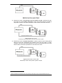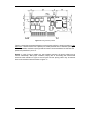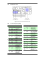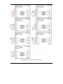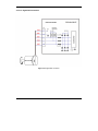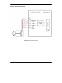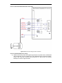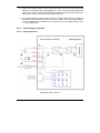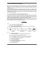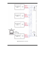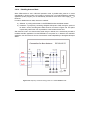
1
ElectroCraft PRO-A0xV36x-PECAN Programmable Servo Drive Programmable Servo Drive for Step, DC, Brushless DC and AC Motors ElectroCraft Document Number A11221 Rev 1 © ElectroCraft 2013 Technical Reference ELECTROCRAFT PRO-A0xV36x-PE Technical Reference ElectroCraft Document Number A11221 ElectroCraft 4480 Varsity Drive, Suite G Ann Arbor, MI 48108 www.electrocraft.com Read This First While ElectroCraft believes that the information and guidance given in this manual is correct, all parties must rely upon their own skill and judgment when making use of it. ElectroCraft does not assume any liability to anyone for any loss or damage caused by any error or omission in the work, whether such error or omission is the result of negligence or any other cause. Any and all such liability is disclaimed. All rights reserved. No part or parts of this document may be reproduced or transmitted in any form or by any means, electrical or mechanical including photocopying, recording or by any information-retrieval system without permission in writing from ElectroCraft, Inc. The information in this document is subject to change without notice. About This Manual This book is a technical reference manual for the PRO-A0xV36 family of programmable servo drives, including the following products: PRO-A02V36x-PE-CAN PRO-A04V36x-PE-CAN In order to operate the PRO-A0xV36 drives, you need to perform the following 3 steps: Step 1 Hardware installation Step 2 Drive setup using the ElectroCraft PROconfig software for drive commissioning Step 3 Motion programming using one of the options: A CANopen master1 The drive’s built-in motion controller executing a ElectroCraft Motion PROgramming Language (MPL) program developed using ElectroCraft MotionPRO Developer software A MPL_LIB motion library for PCs (Windows or Linux) A MPL_LIB motion library for PLCs A distributed control approach which combines the above options, like for example a host calling motion functions programmed on the drives in MPL This manual covers Step 1 in detail. It describes the PRO-A0xV36 hardware including the technical data, the connectors and the wiring diagrams needed for installation. The manual also presents an overview of the following steps, and includes the scaling factors between the real SI units and the drive internal units. For detailed information regarding the next steps, refer to the related documentation. Notational Conventions This document uses the following conventions: • PRO-A0xV36x-PE – all products described in this manual • IU units – Internal units of the drive • SI units – International standard units (meter for length, seconds for time, etc.) • MPL – ElectroCraft Motion PROgramming Language • MPLCAN – ElectroCraft protocol for exchanging MPL commands via CAN-bus 1 when PRO-A0xV36 is set in CANopen mode © ElectroCraft 2013 III PRO-A0xV36-PE Technical Reference Related Documentation Help Screens within the PROconfig software – describes how to use PROconfig to quickly setup any ElectroCraft PRO Series drive for your application using only 2 dialogues. The output of PROconfig is a set of setup data that can be downloaded into the drive EEPROM or saved on a PC file. At power-on, the drive is initialized with the setup data read from its EEPROM. With PROconfig it is also possible to retrieve the complete setup information from a drive previously programmed. PROconfig is part of the ElectroCraft Motion PRO Suite. Motion PRO Suite is available as part of a PRO Series Drive Evaluation Kit. Please contact ElectroCraft or your local ElectroCraft sales representative for more information on obtaining MotionPRO Suite or an evaluation kit. PRO Series CANOpen Programming Manual (Document No. A11226) – explains how to program the PRO Series family of programmable drives using CANopen protocol and describes the associated object dictionary for CiA 301 v.4.2 application layer and communication profile, CiA WD 305 v.2.2.13 layer settings services and protocols and CiA DSP 402 v3.0 device profile for drives and motion control now included in IEC 61800-7-1 Annex A, IEC 61800-7-201 and IEC 61800-7-301 standards Motion Programming using ElectroCraft MotionPRO Suite (Document No. A11229) – describes how to use the MotionPRO Suite to create motion programs using the ElectroCraft Motion PROgramming Language (MPL). The MotionPRO Suite includes PROconfig for the drive/motor setup, and a Motion Editor for the motion programming. The Motion Editor provides a simpleway of creating motion programs and automatically generates all the MPL instructions. With MotionPRO Developer you can fully benefit from a key advantage of ElectroCraft drives – their capability to execute complex motions without requiring an external motion controller, thanks to their built-in motion controller. Motion PRO Suite is available as part of a PRO Series Drive Evaluation Kit. Please contact ElectroCraft or your local ElectroCraft sales representative for more information on obtaining MotionPRO Suite or an evaluation kit. PRO Series and LIB v2.0 (Document No. A11230) – explains how to program in C, C++, C#, Visual Basic or Delphi Pascal a motion application for the ElectroCraft programmable drives using using MPL_LIB v2.0, ElectroCraft Document Number A11230 motion control library for PCs. The MPL_LIB includes ready-to-run examples that can be executed on Windows or Linux (x86 and x64). PRO Series and LabVIEW v2.0 Compatibility (Document No. A11231) – explains how to program in LabVIEW a motion application for the ElectroCraft programmable drives using MPL_LIB_Labview v2.0 motion control library for PCs. The MPL_LIB_LabVIEW includes over 40 ready-to-run examples. PRO Series and PLC Siemens Series S7-300 or S7-400 (Document No. A11232) – explains how to program in a PLC Siemens series S7-300 or S7-400 a motion application for the ElectroCraft programmable drives using MPL_LIB_S7 motion control library. The MPL_LIB_S7 library is IEC61131-3 compatible. PRO Series and PLC Omron Series CJ1 (Document No. A11233) – explains how to program in a PLC Omron series CJ1 a motion application for the ElectroCraft programmable drives using MPL_LIB_CJ1 motion control library for PLCs. The MPL_LIB_CJ1 library is IEC61131-3 compatible. PRO Series and X20 (Document No. A11234) – explains how the MPL_LIB_X20 library is IEC61131-3 compatible. ElectroCAN (Document No. A11235) – presents ElectroCAN protocol – an extension of the CANopen communication profile used for MPL commands © ElectroCraft 2013 IV PRO-A0xV36-PE Technical Reference QS-PRO-A0xV36 (Document No. 11237) – describes the PRO-A0xV36 Quick-Start board included in the PRO-A0xV36 Evaluation Kits © ElectroCraft 2013 V PRO-A0xV36-PE Technical Reference If you Need Assistance … If you want to … Contact ElectroCraft at … Visit ElectroCraft online World Wide Web: http://www.electrocraft.com/ Receive general information or assistance (see Note) World Wide Web: http://www.electrocraft.com Email: [email protected] Ask questions about product operation or report suspected problems (see Note) Tel : +1 734.662-7771 Email: [email protected] Make suggestions about, or report errors in documentation (see Note) Mail: ElectroCraft Michigan 4480 Varsity Drive, Suite G Ann Arbor, MI 48108 USA © ElectroCraft 2013 VI PRO-A0xV36-PE Technical Reference Table of Contents Read This First ................................................................................................... III 1. Safety information .................................................................................... 11 1.1. 1.2. 2. Warnings ................................................................................................ 2 Cautions ................................................................................................. 2 Product Overview ....................................................................................... 4 2.1. 2.2. 2.3. 2.4. 2.5. Introduction............................................................................................. 4 Key Features .......................................................................................... 5 Supported Motor-Sensor Configurations ................................................ 7 PRO-A0xV36Drive Dimensions ............................................................ 12 Electrical Specifications ........................................................................ 13 2.5.1. 2.5.2. 2.5.3. 2.5.4. 2.5.5. 2.5.6. 2.5.7. 2.5.8. 2.5.9. 2.5.10. 2.5.11. 2.5.12. 2.5.13. 2.5.14. 2.5.15. 2.5.16. 2.5.17. 2.5.18. 3. Operating Conditions ................................................................................... 13 Storage Conditions ...................................................................................... 13 Mechanical Mounting ................................................................................... 13 Environmental Characteristics ..................................................................... 13 Logic Supply Input (+VLOG) ........................................................................... 14 Motor Supply Input (+VMOT) .......................................................................... 14 Motor Outputs (A/A+, B/A-, C/B+, BR/B-) .................................................... 14 Digital Inputs (IN0, IN1, IN2/LSP, IN3/LSN, IN4/Enable) ............................. 15 Digital Outputs (OUT0, OUT1, OUT2/Error, OUT3/ Ready) ........................ 15 Digital Hall Inputs (Hall1, Hall2, Hall3) ...................................................... 16 Encoder Inputs (A/A+, A-, B/B+, B-, Z/Z+, Z-) .......................................... 16 Linear Hall Inputs (LH1, LH2, LH3) ........................................................... 17 Sin-Cos Encoder Inputs (Sin+, Sin-, Cos+, Cos-) ..................................... 17 Analog 0…5V Inputs (REF, FDBK) ........................................................... 17 Axis ID Inputs (AxisID 0, AxisID 1, Axis ID 2) ........................................... 18 RS-232 ...................................................................................................... 18 CAN-Bus ................................................................................................... 18 Supply Output (+5V) ................................................................................. 18 Step 1. Hardware Installation .................................................................. 21 3.1. Mechanical Mounting ........................................................................... 21 3.1.1. Vertical Mounting ......................................................................................... 21 3.1.2. Horizontal Mounting ..................................................................................... 22 3.2. 3.3. 3.4. Motherboard PCB Design..................................................................... 24 Mating Connector and Retainer ............................................................ 27 Connector and Connection Diagrams .................................................. 27 3.4.1. Connector Layout ......................................................................................... 27 3.4.2. Identification Labels ..................................................................................... 28 3.4.3. J1 Connector pinout (A Side) ....................................................................... 28 © ElectroCraft 2013 VII PRO-A0xV36-PE Technical Reference 3.4.4. 3.4.5. 3.4.6. 3.4.7. 3.4.8. 3.4.9. 3.4.10. 3.4.11. 3.4.12. 3.4.13. 3.4.14. 4. Step 2. Drive Setup .................................................................................. 59 4.1. 4.2. Installing PROconfig ............................................................................. 59 Getting Started with PROconfig ........................................................... 59 4.2.1. 4.2.2. 4.2.3. 4.2.4. 4.3. 4.4. 4.5. 5. J1 Connector pinout (B Side) ....................................................................... 29 Operation Mode and Axis ID Selection ........................................................ 30 24V Digital I/O Connection ........................................................................... 38 5V Digital I/O Connection ............................................................................. 39 Analog Inputs Connection ............................................................................ 40 Motor connections ........................................................................................ 42 Feedback connections .............................................................................. 46 Power Supply Connection ........................................................................ 51 Serial RS-232 connection ......................................................................... 54 CAN-bus connection ................................................................................. 55 Disabling Autorun Mode ........................................................................... 58 Establish communication ............................................................................. 60 Setup drive/motor ......................................................................................... 61 Download setup data to drive/motor ............................................................ 62 Evaluate drive/motor behavior (optional) ..................................................... 63 Changing the drive Axis ID ................................................................... 64 Setting CANbus rate............................................................................. 66 Creating an Image File with the Setup Data ......................................... 67 Step 3. Motion Programming .................................................................. 68 5.1. Using a CANopen Master (for PRO-A0xV36 CANopen execution) ...... 68 5.1.1. 5.1.2. 5.1.3. 5.1.4. 5.1.5. 5.2. Using the built-in Motion Controller and MPL ....................................... 70 5.2.1. 5.2.2. 5.2.3. 5.2.4. 5.3. ElectroCraft Motion PROgramming Language Overview............................. 70 Installing MotionPRO Suite .......................................................................... 70 Getting Started with MotionPRO Suite ......................................................... 71 Creating an Image File with the Setup Data and the MPL Program ............ 77 Combining CANopen /or other host with MPL ...................................... 77 5.3.1. 5.3.2. 5.3.3. 5.3.4. 5.3.5. 5.4. 5.5. CiA-301 Application Layer and Communication Profile Overview ............... 68 CiA-305 Layer Setting Services (LSS) and Protocols Overview .................. 69 CiA-402 and Manufacturer Specific Device Profile Overview ...................... 69 ElectroCAN Extension ................................................................................. 69 Checking Setup Data Consistency .............................................................. 69 Using MPL Functions to Split Motion between Master and Drives .............. 78 Executing MPL programs ............................................................................. 78 Loading Automatically Cam Tables Defined in MotionPRO Developer ....... 78 Customizing the Homing Procedures .......................................................... 78 Customizing the Drive Reaction to Fault Conditions .................................... 79 Using Motion Libraries for PC-based Systems ..................................... 79 Using Motion Libraries for PLC-based Systems ................................... 80 © ElectroCraft 2013 VIII PRO-A0xV36-PE Technical Reference 6. Scaling factors.......................................................................................... 80 6.1. Position units ........................................................................................ 81 6.1.1. 6.1.2. 6.1.3. 6.1.4. 6.1.5. 6.1.6. 6.2. Speed units .......................................................................................... 83 6.2.1. 6.2.2. 6.2.3. 6.2.4. 6.2.5. 6.2.6. 6.2.7. 6.3. Brushless / DC brushed motor with quadrature encoder on motor .............. 86 Brushless motor with linear Hall signals ...................................................... 86 DC brushed motor with quadrature encoder on load and tacho on motor ... 87 Step motor open-loop control. No feedback device ..................................... 87 Step motor open-loop control. Incremental encoder on load ....................... 88 Step motor closed-loop control. Incremental encoder on motor .................. 88 Brushless motor with sine/cosine encoder on motor.................................... 89 Jerk units .............................................................................................. 89 6.4.1. 6.4.2. 6.4.3. 6.4.4. 6.4.5. 6.4.6. 6.4.7. 6.5. 6.6. 6.7. 6.8. 6.9. 6.10. 6.11. Brushless / DC brushed motor with quadrature encoder on motor .............. 83 Brushless motor with linear Hall signals ...................................................... 83 DC brushed motor with quadrature encoder on load and tacho on motor ... 84 DC brushed motor with tacho on motor ....................................................... 84 Step motor open-loop control. No feedback device ..................................... 84 Step motor closed-loop control. Incremental encoder on motor .................. 85 Brushless motor with sine/cosine encoder on motor.................................... 85 Acceleration units ................................................................................. 86 6.3.1. 6.3.2. 6.3.3. 6.3.4. 6.3.5. 6.3.6. 6.3.7. 6.4. Brushless / DC brushed motor with quadrature encoder on motor .............. 81 Brushless motor with linear Hall signals ...................................................... 81 DC brushed motor with quadrature encoder on load and tacho on motor ... 81 Step motor open-loop control. No feedback device ..................................... 82 Step motor open-loop control. Incremental encoder on load ....................... 82 Brushless motor with sine/cosine encoder on motor.................................... 82 Brushless / DC brushed motor with quadrature encoder on motor .............. 89 Brushless motor with linear Hall signals ...................................................... 90 DC brushed motor with quadrature encoder on load and tacho on motor ... 90 Step motor open-loop control. No feedback device ..................................... 90 Step motor open-loop control. Incremental encoder on load ....................... 91 Step motor closed-loop control. Incremental encoder on motor .................. 91 Brushless motor with sine/cosine encoder on motor.................................... 91 Current units ......................................................................................... 92 Voltage command units ........................................................................ 92 Voltage measurement units .................................................................. 93 Time units ............................................................................................. 93 Master position units ............................................................................ 93 Master speed units ............................................................................... 93 Motor position units .............................................................................. 93 6.11.1. 6.11.2. 6.11.3. 6.11.4. 6.11.5. Brushless / DC brushed motor with quadrature encoder on motor ........... 93 Brushless motor with linear Hall signals ................................................... 94 DC brushed motor with quadrature encoder on load and tacho on motor 94 Step motor open-loop control. No feedback device .................................. 94 Step motor open-loop control. Incremental encoder on load .................... 94 © ElectroCraft 2013 IX PRO-A0xV36-PE Technical Reference 6.11.6. 6.11.7. Step motor closed-loop control. Incremental encoder on motor ............... 94 Brushless motor with sine/cosine encoder on motor ................................ 95 6.12. Motor speed units ................................................................................. 95 6.12.1. 6.12.2. 6.12.3. 6.12.4. 6.12.5. on load 6.12.6. 6.12.7. 7. Brushless / DC brushed motor with quadrature encoder on motor ........... 95 Brushless motor with linear Hall signals ................................................... 95 DC brushed motor with quadrature encoder on load and tacho on motor 96 DC brushed motor with tacho on motor .................................................... 96 Step motor open-loop control. No feedback device or incremental encoder 97 Step motor closed-loop control. Incremental encoder on motor ............... 97 Brushless motor with sine/cosine encoder on motor ................................ 97 Memory Map ............................................................................................. 99 © ElectroCraft 2013 X PRO-A0xV36-PE Technical Reference This page is empty 1. Safety information © ElectroCraft 2013 XI PRO-A0xV36-PE Technical Reference Read carefully the information presented in this chapter before carrying out the drive installation and setup! It is imperative to implement the safety instructions listed hereunder. This information is intended to protect you, the drive and the accompanying equipment during the product operation. Incorrect handling of the drive can lead to personal injury or material damage. Only qualified personnel may install, set up, operate and maintain the drive. A “qualified person” has the knowledge and authorization to perform tasks such as transporting, assembling, installing, commissioning and operating drives. The following safety symbols are used in this manual: WARNING! SIGNALS A DANGER THAT MIGHT CAUSE BODILY INJURY TO THE OPERATOR. MAY INCLUDE INSTRUCTIONS TO PREVENT THIS SITUATION CAUTION! SIGNALS A DANGER FOR THE DRIVE, WHICH MIGHT DAMAGE THE PRODUCT OR OTHER EQUIPMENT. MAY INCLUDE INSTRUCTIONS TO AVOID THIS SITUATION CAUTION! INDICATES AREAS SENSITIVE TO ELECTROSTATIC DIS-CHARGES (ESD), WHICH REQUIRE HANDLING IN AN ESD PROTECTED ENVIRONMENT 1.1. Warnings WARNING! TO AVOID ELECTRIC ARCING AND HAZARDS, NEVER PLUG / UNPLUG THE PRO-A0xV36 FROM IT’S SOCKET WHILE THE POWER SUPPLIES ARE ON ! WARNING! THE DRIVE MAY HAVE HOT SURFACES DURING OPERATION. WARNING! DURING DRIVE OPERATION, THE CONTROLLED MOTOR WILL MOVE. KEEP AWAY FROM ALL MOVING PARTS TO AVOID INJURY 1.2. Cautions CAUTION! THE POWER SUPPLIES CONNECTED TO THE DRIVE MUST COMPLY WITH THE PARAMETERS SPECIFIED IN THIS DOCUMENT CAUTION! TROUBLESHOOTING AND SERVICING ARE PERMITTED ONLY FOR PERSONNEL AUTHORISED BY ELECTROCRAFT CAUTION! THE PRO-A0xV36 IS AN ELECTROSTATICALLY SENSITIVE DEVICE, WHICH WILL BE DAMAGED BY INCORRECT HANDLING. THEREFORE THE DRIVE © ElectroCraft 2013 2 PRO-0xV36-PE-CAN Technical Reference SHALL BE REMOVED FROM ITS ORIGINAL PACKAGE ONLY IN AN ESD PROTECTED ENVIRONMENT ! To prevent electrostatic damage, avoid contact with insulating materials, such as synthetic fabrics or plastic surfaces. In order to discharge static electricity build-up, place the drive on a grounded conductive surface and also ground yourself. © ElectroCraft 2013 3 PRO-0xV36-PE-CAN Technical Reference 2. Product Overview 2.1. Introduction The PRO-A0xV36 is a family of fully digital programmable servo drives, based on the latest DSP technology and they offer unprecedented drive performance combined with an embedded motion controller. Suitable for control of brushless DC, brushless AC (vector control), DC brushed motors and step motors, the PRO-A0xV36 drives accept as position feedback incremental encoders (quadrature or sine/cosine) and linear Halls signals. All drives perform position, speed or torque control and work in single, multi-axis or stand-alone configurations. Thanks to the embedded motion controller, the PRO-A0xV36 drives combine controller, drive and PLC functionality in a single compact unit and are capable to execute complex motions without requiring intervention of an external motion controller. Using the highlevel ElectroCraft Motion PROgramming Language (MPL) the following operations can be executed directly at drive level: Setting various motion modes (profiles, PVT, PT, electronic gearing1 or camming1, etc.) Changing the motion modes and/or the motion parameters Executing homing sequences Controlling the program flow through: Conditional jumps and calls of MPL functions MPL interrupts generated on pre-defined or programmable conditions (protections triggered, transitions on limit switch or capture inputs, etc.) Waits for programmed events to occur Handling of digital I/O and analog input signals Executing arithmetic and logic operations Performing data transfers between axes Controlling motion of an axis from another one via motion commands sent between axes Sending commands to a group of axes (multicast). This includes the possibility to start simultaneously motion sequences on all the axes from the group Synchronizing all the axes from a network By implementing motion sequences directly at drive level you can really distribute the intelligence between the master and the drives in complex multi-axis applications, reducing both the development time and the overall communication requirements. For example, instead of trying to command each movement of an axis, you can program the drives using MPL to execute complex motion tasks and inform the master when these tasks are done. Thus, for each axis control the master job may be reduced at: calling MPL functions stored in the drive EEPROM and waiting for a message, which confirms the MPL functions execution completion. All PRO-A0xV36 drives are equipped with a serial RS232 and a CAN 2.0B interface and can be set (hardware, via an AxisID input level) to operate in 2 modes: CANopen MPLCAN When CANopen mode is selected, the PRO-A0xV36 conforms to CiA 301 v4.2 application layer and communication profile, CiA WD 305 v2.2.13 and CiA DSP 402 v3.0 device profile for drives 1 Available if the master axis sends its position via a communication channel © ElectroCraft 2013 4 PRO-0xV36-PE-CAN Technical Reference and motion control, now included in IEC 61800-7-1 Annex A, IEC 61800-7-201 and IEC 61800-7301 standards. In this mode, the PRO-A0xV36 may be controlled via a CANopen master. As a bonus, PRO-A0xV36 offers a CANopen master the option to call motion sequences, written in MPL and stored in the drive EEPROM, using manufacturer specific objects (see for details par. 5.3). When MPLCAN mode is selected, the PRO-A0xV36 behaves as standard ElectroCraft programmable drive and conforms to ElectroCraft protocol for exchanging MPL commands via CAN-bus. When MPLCAN protocol is used, it is not mandatory to have a master. Any PROA0xV36 can be set to operate standalone, and may play the role of a master to coordinate both the network communication/synchronization and the motion application via MPL commands sent directly to the other drives. When higher level coordination is needed, apart from a CANopen master, the PRO-A0xV36 drives can also be controlled via a PC or a PLC using one of the MPL_LIB motion libraries. For PRO-A0xV36 commissioning PROconfig or MotionPRO Developer PC applications may be used. PROconfig is a subset of MotionPRO Suite, including only the drive setup part. The output of PROconfig is a set of setup data that can be downloaded into the drive EEPROM or saved on a PC file. At power-on, the drive is initialized with the setup data read from its EEPROM. With PROconfig it is also possible to retrieve the complete setup information from a drive previously programmed. PROconfig shall be used for drive setup in all cases where the motion commands are sent exclusively from a master. Hence neither the PRO-A0xV36 MPL programming capability nor the drive camming mode are used. MotionPRO Suite includes PROconfig for the drive setup, and a Motion Editor for the motion programming. The Motion Editor provides a simple way of creating motion programs and automatically generates all the MPL instructions. With MotionPRO Developer you can fully benefit from a key advantage of ElectroCraft drives – their capability to execute complex motions without requiring an external motion controller, thanks to their built-in motion controllers. MotionPRO Developer, shall be used to program motion sequences in MPL. This is the PRO-A0xV36 typical operation mode when MPLCAN protocol is selected. MotionPRO Developer shall also be used with CANopen protocol, if the user wants to call MPL functions stored in the drive EEPROM or to use the camming mode. With camming mode, MotionPRO Developer offers the possibility to quickly download and test a cam profile and also to create a .sw file (see par. 5.2.4) with the cam data. The .sw file can be afterwards stored in a master and downloaded to the drive, wherever needed. 2.2. Key Features • Fully digital servo drive suitable for the control of rotary or linear brushless, DC brush, and step motors • Very compact design • Standard PCIe 4x mating connector • Sinusoidal (FOC) or trapezoidal (Hall-based) control of brushless motors • Open or closed-loop control of 2 and 3-phase steppers • Various modes of operation, including: torque, speed or position control; position or speed profiles, external analog reference or sent via a communication bus • ElectroCraft Motion PROgramming Language (MPL) instruction set for the definition and execution of motion sequences • Standalone operation with stored motion sequences • Various motion programming modes: • Position profiles with trapezoidal or S-curve speed shape • Position, Velocity, Time (PVT) 3rd order interpolation • Position, Time (PT) 1st order interpolation © ElectroCraft 2013 5 PRO-0xV36-PE-CAN Technical Reference • • • • • • • • • • • • • • • • • • Electronic gearing and camming1 • 35 Homing modes Single-ended and RS-422 differential encoder interface Single-ended, open collector Digital Hall sensor interface Linear Hall sensor interface Analog Sin/Cos encoder interface (differential 1Vpp) SSI, EnDAT, BiSS absolute encoders and resolver feedback possible with an additional feedback extension module 2 analog inputs: 12-bit, 0-5V (Reference, Feedback) or general-purpose 5 digital inputs: 5-36V, NPN: Enable, Limit switch +, Limit switch –, 2 general-purpose 4 digital outputs : 5-36V, 0.5A, NPN open-collector: Ready, Error, 2 general-purpose RS-232 serial interface (up to 115200 bps) CAN-bus 2.0B up to 1Mbit/s with hardware axis ID selection2 Two operation modes: • CANopen – conforming with CiA 301 v4.2, CiA WD 305 v2.2.13 and CiA DSP 402 v3.0 • MPLCAN – programmable drive conforming with ElectroCraft protocol for exchanging MPL commands via CAN-bus 1K × 16 internal SRAM memory 2 4K × 16 E ROM to store MPL programs and data PWM switching frequency up to 100kHz Motor supply: 9-36V Logic supply: 7-36V.Separate supply is optional Output current: • PRO-A02V36A-PE-CAN:: 2A2 continuous; 3.2A peak • PRO-A04V36A-PE-CAN:: 4A3 continuous; 10A peak • Operating ambient temperature: 0-40°C (over 40°C with derating) • Hardware Protections: • Short-circuit between motor phases • Short-circuit from motor phases to ground • Over-voltage • Under-voltage • Over-current 1 2 2 3 Available if the master axis sends its position via a communication channel 127 addresses in CANopen mode, 196 addresses in MPLCAN mode 2A cont. with DC, step and BLDC motors (trapezoidal), 2A amplitude (1.41ARMS) for PMSM (sinusoidal) 4A cont. with DC, step and BLDC motors (trapezoidal), 4A amplitude (2.82ARMS) for PMSM (sinusoidal) © ElectroCraft 2013 6 PRO-0xV36-PE-CAN Technical Reference 2.3. Supported Motor-Sensor Configurations PRO-A0xV36 supports the following configurations: 1. Position, speed or torque control of a brushless AC rotary motor with an incremental quadrature encoder on its shaft. The brushless motor is vector controlled like a permanent magnet synchronous motor. It works with sinusoidal voltages and currents. Scaling factors take into account the transmission ratio between motor and load (rotary or linear). Therefore, the motion commands (for position, speed and acceleration) expressed in SI units (or derivatives) refer to the load1, while the same commands, expressed in IU units, refer to the motor. Figure 2.1. Brushless AC rotary motor. Position / speed / torque control. Quadrature encoder on motor. 2. Position, speed or torque control of a brushless AC rotary motor with an incremental sine/cosine encoder on its shaft. The brushless motor is vector controlled like a permanent magnet synchronous motor. It works with sinusoidal voltages and currents. Scaling factors take into account the transmission ratio between motor and load (rotary or linear). Therefore, the motion commands (for position, speed and acceleration) expressed in SI units (or derivatives) refer to the load1, while the same commands, expressed in IU units, refer to the motor. Figure 2.2. Brushless AC rotary motor. Position/speed/torque control. Sine/cosine incremental encoder on motor 3. Position, speed or torque control of a brushless AC linear motor with an incremental sine/cosine encoder. The brushless motor is vector controlled like a permanent magnet synchronous motor. It works with sinusoidal voltages and currents. Scaling factors take into account the transmission ratio between motor and load (rotary or linear). Therefore, the motion commands (for position, speed and acceleration) expressed in SI units (or derivatives) refer to the load, while the same commands, expressed in IU units, refer to the motor. 1 Motion commands can be referred to the motor by setting in PROconfig a rotary to rotary transmission with ratio 1:1 © ElectroCraft 2013 7 PRO-0xV36-PE-CAN Technical Reference Figure 2.3. Brushless AC linear motor. Position/speed/torque control. Sine/cosine incremental encoder on motor 4. Position, speed or torque control of a brushless DC rotary motor with digital Hall sensors and an incremental quadrature encoder on its shaft. The brushless motor is controlled using Hall sensors for commutation. It works with rectangular currents and trapezoidal BEMF voltages. Scaling factors take into account the transmission ratio between motor and load (rotary or linear). Therefore, the motion commands (for position, speed and acceleration) expressed in SI units (or derivatives) refer to the load, while the same commands, expressed in IU units, refer to the motor. Figure 2.4. Brushless DC rotary motor. Position / speed / torque control. Hall sensors and quadrature encoder on motor. 5. Position, speed or torque control of a brushless AC linear motor with an incremental quadrature linear encoder on the track. The brushless motor is vector controlled like a permanent magnet synchronous motor. It works with sinusoidal voltages and currents. Scaling factors take into account the transmission ratio between motor and load (linear or rotary). Therefore, the motion commands (for position, speed and acceleration) expressed in SI units (or derivatives) refer to the load1, while the same commands, expressed in IU units, refer to the motor. Figure 2.5. Brushless AC rotary motor with incremental quadrature linear encoder. Position / speed / torque control. 6. Position, speed or torque control of a brushless AC rotary motor with linear Hall signals. The brushless motor is vector controlled like a permanent magnet synchronous motor. It works with sinusoidal voltages and currents. Scaling factors take into account the transmission ratio between motor and load (rotary or linear). Therefore, the motion 1 Motion commands can be referred to the motor by setting in PROconfig a linear to linear transmission with ratio 1:1 © ElectroCraft 2013 8 PRO-0xV36-PE-CAN Technical Reference commands (for position, speed and acceleration) expressed in SI units (or derivatives) refer to the load2, while the same commands, expressed in IU units, refer to the motor. Figure 2.6. Brushless AC rotary motor with linear Hall signals. Position / speed / torque control. 7. Position, speed or torque control of a brushless AC linear motor with linear Hall signals. The brushless motor is vector controlled like a permanent magnet synchronous motor. It works with sinusoidal voltages and currents. Scaling factors take into account the transmission ratio between motor and load (rotary or linear). Therefore, the motion commands (for position, speed and acceleration) expressed in SI units (or derivatives) refer to the load, while the same commands, expressed in IU units, refer to the motor. Figure 2.7. Brushless AC linear motor with linear Hall signals. Position / speed / torque control. 8. Position, speed or torque control of a DC brushed rotary motor with an incremental quadrature encoder on its shaft. Scaling factors take into account the transmission ratio between motor and load (rotary or linear). Therefore, the motion commands (for position, speed and acceleration) expressed in SI units (or derivatives) refer to the load1, while the same commands, expressed in IU units, refer to the motor. 2 1 Motion commands can be referred to the motor by setting in PROconfig a rotary to rotary transmission with ratio 1:1 Motion commands can be referred to the motor by setting in PROconfig a rotary to rotary transmission with ratio 1:1 © ElectroCraft 2013 9 PRO-0xV36-PE-CAN Technical Reference Figure 2.8. DC brushed rotary motor. Position / speed / torque control. Quadrature encoder on motor. 9. Load position control using an incremental quadrature encoder on load, combined with speed control of a DC brushed rotary motor having a tachometer on its shaft. The motion commands (for position, speed and acceleration) in both SI and IU units refer to the load. Figure 2.9. DC brushed rotary motor. Position / speed / torque control. Quadrature encoder on load plus tachometer on motor. 10. Speed or torque control of a DC brushed rotary motor with a tachometer on its shaft. Scaling factors take into account the transmission ratio between motor and load (rotary or linear). Therefore, the motion commands (for speed and acceleration) expressed in SI units (or derivatives) refer to the load1, while the same commands, expressed in IU units, refer to the motor. Figure 2.10. DC brushed rotary motor. Speed/torque control. Tachometer on motor. 11. Open-loop control of a 2 or 3-phase step motor in position or speed. Scaling factors take into account the transmission ratio between motor and load (rotary or linear). Therefore, the motion commands (for position, speed and acceleration) expressed in SI units (or derivatives) refer to the load, while the same commands, expressed in IU units, refer to the motor. 1 Motion commands can be referred to the motor by setting in PROconfig a rotary to rotary transmission with ratio 1:1 © ElectroCraft 2013 10 PRO-0xV36-PE-CAN Technical Reference Figure 2.11. No position or speed feedback. Open-loop control: motor position or speed. 12. Closed-loop control of load position using an encoder on load, combined with openloop control of a 2 or 3-phase step motor in speed, with speed reference provided by the position controller. The motion commands in both SI and IU units refer to the load. Figure 2.12. Encoder on load. Closed-loop control: load position, open-loop control: motor speed. 13. Closed-loop control of a 2-phase step motor in position, speed or torque. Scaling factors take into account the transmission ratio between motor and load (rotary or linear). Therefore, the motion commands expressed in SI units (or derivatives) refer to the load1, while the same commands, expressed in IU units refer to the motor. Figure 2.13. Encoder on motor shaft. Closed-loop control: motor position, speed or torque. 1 Motion commands can be referred to the motor by setting in PROconfig a rotary to rotary transmission with ratio 1:1 © ElectroCraft 2013 11 PRO-0xV36-PE-CAN Technical Reference 2.4. PRO-A0xV36Drive Dimensions Figure 2.14. PRO-A0xV36 drive dimensions All dimensions are in mm. The drawings are not to scale. © ElectroCraft 2013 12 PRO-0xV36-PE-CAN Technical Reference 2.5. Electrical Specifications All parameters measured under the following conditions (unless otherwise specified): Tamb = 0…40°C, VLOG = 24 VDC; VMOT = 36VDC; Supplies start-up / shutdown sequence: -anyLoad current (sinusoidal amplitude / continuous BLDC,DC,stepper) = 2A PRO-A02V36; 4A PRO-A04V36. 2.5.1. Operating Conditions Min. 1 Ambient temperature Ambient humidity Non-condensing 2 Altitude / pressure 2.5.2. Altitude (referenced to sea level) Ambient Pressure Ambient humidity 0 +40 ºC 90 %Rh 0 ÷ 2.5 2 Km 0.75 ÷ 1 10.0 Atm Typ. Max. Units -0.1 0 2 -40 +85 ºC 0 100 %Rh 0 10.0 atm Not powered; applies to any accessible part ±0.5 kV Original packaging ±15 kV Non-condensing Ambient Pressure ESD capability (Human body model) Mechanical Mounting Min. Typ. Max. Units 3 Airflow natural convection , closed box Spacing required for vertical mounting (see Figure 3.2) Spacing required for horizontal mounting (see Figure 3.5) Insertion force Extraction force Between adjacent drives 30 mm Between drives and nearby walls 30 mm Between drives and roof-top 20 mm Between adjacent drives 4 mm Between drives and nearby walls 5 mm Space needed for drive removal 10 mm Between drives and roof-top 15 mm Using recommended mating connectors; without retainer 20 5 36 10 N N Environmental Characteristics Min. Without mating connector / retainer Size ( Length x Width x Height ) With recommended mating vertical connector and retainer. Height above PCB surface. With recommended mating horizontal 1 Units 0 Min. 2.5.4. Max. Storage Conditions Ambient temperature 2.5.3. Typ. Typ. Max. Units 56 x 28.8 x 7.6 mm ~2.2 x 1.1 x 0.3 inch 63.3 x 32.6 x 16.3 mm ~2.5 x 1.3 x 0.64 inch 56 x 41.2 x 7.6 mm Operating temperature can be extended up to +65ºC with reduced current and power ratings. See Figure 2.15 and Figure 2.20 2 PRO-04V36 can be operated in vacuum (no altitude restriction), but at altitudes over 2,500m, current and power rating are reduced due to thermal dissipation efficiency. See Figure 2.16 and Figure 2.21 3 In case of forced cooling (conduction or ventilation) the spacing requirements may drop down to mechanical tolerances as long as the ambient temperature is kept below the maximum operating limit © ElectroCraft 2013 13 PRO-0xV36-PE-CAN Technical Reference connector. Height above PCB surface. ~2.2 x 1.6 x 0.3 inch 10 g Weight Power dissipation Idle (no load) 1 Operating 3 Efficiency 98 Cleaning agents Dry cleaning is recommended Protection degree According to IEC60529, UL508 2.5.5. IP00 - Logic Supply Input (+VLOG) Min. Supply voltage Absolute maximum values, drive operating but outside guaranteed parameters Absolute maximum values, surge (duration ≤ 10ms) Supply current † Typ. Max. Units 7 36 VDC 4.9 42 VDC -1 +45 V 125 80 50 40 300 200 125 100 mA Typ. Max. Units +VLOG = 7V +VLOG = 12V +VLOG = 24V +VLOG = 40V Motor Supply Input (+VMOT) Min. Nominal values Supply voltage Absolute maximum values, drive operating but outside guaranteed parameters Absolute maximum values, surge (duration ≤ 10ms) † 9 36 VDC 8.5 40 VDC -1 +45 V 1 5 mA Idle Operating Supply current PROA04V36 -10 ±4 +10 PROA02V36 -3.2 ±2 +3.2 A PROAbsolute maximum value, short- A04V36 circuit condition (duration ≤ † PRO10ms) A02V36 2.5.7. % Only Water- or Alcohol- based Nominal values 2.5.6. W 15 A 5 Motor Outputs (A/A+, B/A-, C/B+, BR/B-) Min. for DC brushed, steppers and BLDC motors with Hall-based trapezoidal control Nominal output current, continuous for PMSM motors with FOC sinusoidal control (sinusoidal amplitude value) for PMSM motors with FOC sinusoidal control (sinusoidal effective value) Motor output current, peak © ElectroCraft 2013 14 Max. 4 PROA02V36 2 PROA04V36 4 PROA02V36 2 PROA04V36 2.82 PROA02V36 1.41 PROA04V36 maximum 2.5s Typ. PROA04V36 -10 +10 Units A A PRO-0xV36-PE-CAN Technical Reference PROA02V36 maximum 24s Short-circuit protection threshold measurement range ±13 ±15 PROA02V36 ±4.3 ±5 5 Nominal output current; including typical mating connector contact resistance Motor electrical time-constant (L/R) Current measurement accuracy 2.5.8. FPWM = 20 kHz Recommended value, for F = 40 kHz ripple ±5% of measurement PWM FPWM = 80 kHz range; +VMOT = 36 V FPWM = 100 kHz FPWM = 20 kHz Absolute minimum value, FPWM = 40 kHz limited by short-circuit FPWM = 80 kHz protection; +VMOT = 36 V FPWM = 100 kHz FPWM = 20 kHz Recommended value, for F = 40 kHz ±5% current measurement PWM FPWM = 80 kHz error due to ripple FPWM = 100 kHz μS 10 ±0.3 ±0.5 V ±0.5 ±1 mA 250 120 60 45 75 25 10 5 250 125 63 50 μH μH µs FS = Full Scale ±4 ±8 Typ. Max. %FS Digital Inputs (IN0, IN1, IN2/LSP, IN3/LSN, IN4/Enable) Min. Default state Input floating (wiring disconnected) Logic HIGH Logic “LOW” 0 Logic “HIGH” Input voltage 2 3 Absolute maximum, surge (duration ≤ 1S) † +30 -20 +40 0.6 Logic “HIGH”; Internal 4.7KΩ pull-up to +3.3 0 Logic “HIGH”; Pulled to +5V 0 0 0.2 2 0 Minimum pulse width Human body model 1 0.15 Logic “HIGH”; Pulled to +24V Input frequency V -10 Logic “LOW”; Pulled to GND ESD protection 0.8 5÷24 Floating voltage (not connected) Absolute maximum, continuous Input current Units TTL / CMOS / LVTTL (3.3V) / Opencollector / NPN / 24V outputs Mode compliance 2.5.9. A A Off-state leakage current Motor inductance (phase-to-phase) +3.2 PROA04V36 Short-circuit protection delay On-state voltage drop -3.2 mA 2.5 150 KHz 3.3 µS ±5 KV Digital Outputs (OUT0, OUT1, OUT2/Error, OUT3/ Ready) Min. Mode compliance All outputs (OUT0, OUT1, OUT2/Error, OUT3/Ready) © ElectroCraft 2013 Units Same as above + LVTTL (3.3V) Not supplied (+VLOG floating or to GND) Output voltage Max. TTL / CMOS / Open-collector / NPN 24V Ready, Error Default state Typ. High-Z (floating) Immediately after power-up OUT0, OUT1 Logic “HIGH” OUT2/Error, OUT3/ Ready Logic “LOW” Normal operation OUT0, OUT1, OUT2/Error Logic “HIGH” OUT3/Ready Logic “LOW”; output current = 0.5A 15 Logic “LOW” 0.2 0.8 V PRO-0xV36-PE-CAN Technical Reference Logic “HIGH”; output current = 0, no load OUT2/Error, OUT3/ Ready OUT0, OUT1 2.9 3 3.3 4 4.5 5 Logic “HIGH”, external load to +VLOG VLOG Absolute maximum, continuous Absolute maximum, surge (duration ≤ 1S) † -0.5 VLOG+0.5 -1 VLOG+1 Logic “LOW”, sink current, continuous 0.5 A 1 A OUT2/Error, OUT3/ Ready 2 mA OUT0, OUT1 4 mA 0.2 mA Logic “LOW”, sink current, pulse ≤ 5 sec. Output current Logic “HIGH”, source current; external load to GND; VOUT >= 2.0V Logic “HIGH”, leakage current; external load to +VLOG; VOUT = VLOG max = 40V 0.1 Minimum pulse width ESD protection Human body model 2 µS ±5 KV 2.5.10. Digital Hall Inputs (Hall1, Hall2, Hall3) Min. Mode compliance Default state Input floating (wiring disconnected) 0 Logic “HIGH” 2 Floating voltage (not connected) † 0.8 5 -10 V +15 Logic “LOW”; Pull to GND 1.2 0 0 mA Logic “HIGH”; Internal 4.7KΩ pull-up to +5 0 2 µS Human body model ±5 KV Minimum pulse width ESD protection Units 4.4 Absolute maximum, surge (duration ≤ 1S) Input current Max. Logic HIGH Logic “LOW” Input voltage Typ. TTL / CMOS / Open-collector 2.5.11. Encoder Inputs (A/A+, A-, B/B+, B-, Z/Z+, Z-) Min. Single-ended mode compliance Leave negative inputs disconnected Typ. Logic “LOW” Input voltage, single-ended mode A/A+, B/B+ Logic “HIGH” 1.8 V 4.5 Logic “LOW” 1.2 Logic “HIGH” V 1.4 Floating voltage (not connected) 4.7 Input current, single-ended mode A/A+, B/B+, Z/Z+ Logic “LOW”; Pull to GND 2.5 3 0 0 Differential mode compliance For full RS422 compliance, see Input voltage, differential mode Input impedance, differential Units 1.6 Floating voltage (not connected) Input voltage, single-ended mode Z/Z+ Max. TTL / CMOS / Open-collector Logic “HIGH”; Internal 2.2KΩ pull-up to +5 0 1 mA TIA/EIA-422-A Hysteresis ±0.06 ±0.1 Common-mode range (A+ to GND, etc.) -7 A+ to A-, B+ to B- 4.2 4.7 Z+ to Z- 6.1 7.2 ±0.2 V +7 KΩ 1 For full RS-422 compliance, 120Ω termination resistors must be connected across the differential pairs, as close as possible to the drive input pins. See Figure 3.21. Differential incremental encoder connection © ElectroCraft 2013 16 PRO-0xV36-PE-CAN Technical Reference Input frequency Minimum pulse width Input voltage, any pin to GND ESD protection Single-ended mode, Open-collector / NPN 0 500 KHz Differential mode, or Single-ended driven by push-pull (TTL / CMOS) 0 10 MHz Single-ended mode, Open-collector / NPN 1 µS Differential mode, or Single-ended driven by push-pull (TTL / CMOS) 50 nS Absolute maximum values, continuous Absolute maximum, surge (duration ≤ 1S) † Human body model -7 +7 -11 +14 ±1 V KV 2.5.12. Linear Hall Inputs (LH1, LH2, LH3) Input voltage Min. Typ. Max. Operational range 0 0.5÷4.5 4.9 Absolute maximum values, continuous -7 +7 -11 +14 Absolute maximum, surge (duration ≤ 1S) Input current Input voltage 0…+5V Interpolation Resolution Depending on software settings † -1 Frequency ESD protection ±0.9 0 Human body model +1 Units V mA 11 bits 1 KHz ±1 KV 2.5.13. Sin-Cos Encoder Inputs (Sin+, Sin-, Cos+, Cos-) Input voltage, differential Absolute maximum values, continuous Absolute maximum, surge (duration ≤ 1S) Input impedance Interpolation Resolution Frequency ESD protection Typ. Max. Units 1 1.25 VPP -1 2.5 4 Sin+ to Sin-, Cos+ to CosOperational range Input voltage, any pin to GND Min. Differential, Sin+ to Sin-, Cos+ to Cos- † 1 -7 +7 -11 +14 4.2 Common-mode, to GND V 4.7 KΩ 2.2 KΩ Depending on software settings 11 bits Sin-Cos interpolation 0 450 KHz Quadrature, no interpolation 0 10 MHz Human body model ±1 KV 2.5.14. Analog 0…5V Inputs (REF, FDBK) Min. Operational range Input voltage Absolute maximum values, continuous Absolute maximum, surge (duration ≤ 1S) Input impedance To GND Resolution Typ. Max. 0 4.95 -12 +18 † Units V ±36 30 KΩ 12 bits Integral linearity ±2 bits Offset error ±2 ±10 bits Gain error ±1% ±3% % FS 2 1 For many applications, an 120Ω termination resistor should be connected across SIN+ to SIN-, and across COS+ to COS-. Please consult the feedback device datasheet for confirmation. 2 “FS” stands for “Full Scale” © ElectroCraft 2013 17 PRO-0xV36-PE-CAN Technical Reference Bandwidth (-3dB) Depending on software settings 0 ESD protection Human body model ±5 1 KHz KV 2.5.15. Axis ID Inputs (AxisID 0, AxisID 1, Axis ID 2) Min. External connections 7 levels Pin current Use to size PCB tracks Typ. Max. ±0.5 4.7KΩ/22KΩ resistor rating 3 ±5 Human body model mA mW 4.7KΩ/22KΩ resistor tolerance ESD protection Units Not connected; Strap to GND; Strap to +5V; 4.7KΩ to GND; 4.7KΩ to +5V; 22KΩ to GND; 22KΩ to +5V; ±5 % KV 2.5.16. RS-232 Min. Standards compliance Typ. Max. Units TIA/EIA-232-C Bit rate Depending on software settings Short-circuit protection 232TX short to GND ESD protection Human body model 9600 115200 Baud Guaranteed ±2 KV 2.5.17. CAN-Bus Min. Standards compliance Bit rate Bus length Typ. Depending on software settings 1Mbps 800Kbps 500Kbps ≤ 250Kbps 125 1000 25 50 100 250 125 Number of CAN nodes/drives Termination resistor Max. Units ISO11898, CiA-301v4.2, CiADSP402v3.0 Between CAN-Hi, CAN-Lo Node addressing Strapping option (AxisID0,1,2) ESD protection Human body model Kbps m - none on-board 1 ÷ 127 (CANopen); 1-195 & 255 (MPLCAN) ±15 KV 2.5.18. Supply Output (+5V) +5V output voltage Current sourced = 250mA +5V output current Min. Typ. Max. 4.8 5 5.2 250 350 Short-circuit protection V mA NOT protected Over-voltage protection ESD protection Units NOT protected Human body model ±1 KV † Stresses beyond values listed under “absolute maximum ratings” may cause permanent damage to the device. Exposure to absolute-maximum-rated conditions for extended periods may affect device reliability. © ElectroCraft 2013 18 PRO-0xV36-PE-CAN Technical Reference Figure 2.15 PRO-A02V36-PE De-rating with ambient temperature Figure 2.16 PRO-A02V36-PE De-rating with altitude Figure 2.17 PRO-A02V36-PE Current De-rating with PWM frequency Figure 2.18 PRO-A02V36-PE Over-current diagram Figure 2.19. PRO-A0xV36 Output Voltage De-rating with PWM 1 frequency Figure 2.20. PRO-A04V36 VX De-rating with ambient temperature 1 VOUT – the output voltage, VMOT – the motor supply voltage © ElectroCraft 2013 19 PRO-0xV36-PE-CAN Technical Reference Figure 2.22. PRO-A04V36-PE Current De-rating with PWM frequency Figure 2.21. PRO-A04V36-PE De-rating with altitude Figure 2.23. PRO-A04V36-PEX Over-current diagram CAUTION! © ElectroCraft 2013 FOR PWM FREQUENCIES LESS THAN 20 KHZ, CORRELATE THE PWM FREQUENCY WITH THE MOTOR PARAMETERS IN ORDER TO AVOID POSSIBLE MOTOR DAMAGE. 20 PRO-0xV36-PE-CAN Technical Reference 3. Step 1. Hardware Installation 3.1. Mechanical Mounting The PRO-A0xV36 drive is intended to be mounted vertically or horizontally on a motherboard equipped with the recommended mating connectors, as specified in chapter 3.3. Several PROA0xV36 drives can be hosted by a single motherboard. For thermal calculations, each PRO-A0xV36 drive can be assumed to generate 1 Watt at idle, and up to 3 Watts (= 10 BTU/hour) worst case while driving a motor. 3.1.1. Vertical Mounting When PRO-A0xV36 is mounted vertically, its overall envelope (size) including the recommended mating connector and an optional retainer is shown in Figure 3.1. In absence of a fixing case holding the drive in the mating connector, the use of the retainers is strongly recommended, to avoid vibration and shock problems. Figure 3.1 Overall dimensions using recommended mating connector and retainer The ensemble motherboard + PRO-A0xV36 drive(s) can be cooled by natural convection. The motherboard can be mounted horizontally or vertically. In both cases, the air temperature must not exceed the limits indicated in Figure 2.15 and Figure 2.20 Figure 3.2. shows the recommended spacing to assure proper airflow by natural convection, in the worst case – closed box done from a plastic (non-metallic) material with no ventilation openings. Whenever possible, ventilation openings shall be foreseen on the top side wall or the box and at the bottom of the lateral walls. When using a horizontal motherboard considerably larger than the size of the hosted PRO-A0xV36 drives, it is recommended to provide ventilation holes also in the motherboard PCB. Remark: In case of using a metallic box, with ventilation openings, all spacing values may be reduced substantially. With proper ventilation, keeping the air surrounding the PRO-A0xV36 inside the limits indicated in Figure 2.15 and Figure 2.20 the spacing values may be reduced down to the mechanical tolerance limits of Figure 3.1. © ElectroCraft 2013 21 PRO-0xV36-PE-CAN Technical Reference 2cm min. 3c m mi n. 3 cm n. mi 3c m mi n. Figure 3.2 Recommended spacing for vertical mounting, worst case: non-metallic, closed box For ventilation holes / slots that pierce a metallic wall also used for EMI shielding, the maximum slot length d should be less than λ/16, where λ is the wavelength corresponding to maximum filtered frequency (ff): 3 ⋅ 10 8 λ d < = 16 16 ⋅ f f If ventilation driven by natural convection is not enough to maintain the temperature surrounding the PRO-A0xV36 drive(s) inside the limits indicated in Figure 2.15 and Figure 2.20 then alternate forced cooling methods must be applied. 3.1.2. Horizontal Mounting When PRO-A0xV36 is mounted horizontally, its overall envelope (size) including the recommended mating connector is shown in Figure 3.3. The PRO-A0xV36 has 6 fixing shoulders that may be used to secure the drive. Figure 3.4 details the fixing shoulders position. Figure 3.3 Overall dimensions for horizontal mounting © ElectroCraft 2013 22 PRO-0xV36-PE-CAN Technical Reference Figure 3.4 Fixing shoulders position Figure 3.5 shows the recommended spacing to assure proper airflow by natural convection, in the worst case – closed box done from a plastic (non-metallic) material with no ventilation openings. Whenever possible, ventilation openings shall be foreseen. Recommendations for their size and position are presented in par.3.1.2. Remark: In case of using a metallic box, with ventilation openings, all spacing values may be reduced substantially. With proper ventilation, keeping the air surrounding the PRO-A0xV36 inside the limits indicated in Figure 2.15 and Figure 2.20 the spacing values may be reduced down to the mechanical tolerance limits of Figure 3.1. © ElectroCraft 2013 23 PRO-0xV36-PE-CAN Technical Reference Figure 3.5 Recommended spacing for horizontal mounting, worst case: non-metallic, closed box 3.2. Motherboard PCB Design The PRO-A0xV36 drive, when plugged vertically into the recommended mating connector and retainer, has the following PCB footprint: Figure 3.6 PCB footprint of mating connector and retainer It is recommended to use a multi-layer PCB for the motherboard, in order to have enough room for routing all the 64 pins of the PRO-A0xV36. Using a 2-layer PCB is possible when some of the PRO-A0xV36 pins remain un-connected. Below is a list of recommendations for the PCB design of the motherboard: • Motor supply and motor outputs: use islands / areas of copper to escape connector area; this will maximize current capability. When using simple tracks, use at least 100mil cross 2 section (75mil track width for 1oz/ft copper thickness) – for PRO-A0xV36. Halve these values for the PRO-A02V36. © ElectroCraft 2013 24 PRO-0xV36-PE-CAN Technical Reference • Motor supply and ground return tracks between PRO-A0xV36 and the nearby VMOT decoupling capacitor are to be considered as EMI sources, and kept to a minimum length. • Place the decoupling capacitors on VMOT and VLOG (see also 3.4.11. Power Supply Connection) as close as physically possible to the PRO-A0xV36, to minimize EM radiated emissions. For un-shielded applications (no metallic box) and typical EMC regulations, the spacing between PRO-A0xV36 and capacitors must be less than 3 centimeters. • In multi-axis applications (multiple PRO-A0xV36 drives on the same motherboard), it is preferable to have a separate decoupling capacitor for each drive’s VMOT. For VLOG it is acceptable to share one decoupling capacitor for two drives. • For stringent EMI requirements, it may be necessary to add common-mode filtering on the motor and/or logic supply inputs. Be sure to use 3-phase EMC filters, not 2-phase filters, in order to fulfill the basic requirement of zero common-mode current through the filter. This is necessary because the ground negative return is shared between VMOT and VLOG. • Motor outputs shall be routed with parallel traces, and minimizing the loop area between these tracks. Avoid placing components above or below the motor output tracks, as these components may become effective antennas radiating EMI. If possible, route all 4 motor outputs in strip-line configuration (above or below a ground plane). • For stringent EMI requirements, it may be necessary to add common-mode inductors on the motor outputs. Place these filters near the PRO-A0xV36, not near the external connector, to reduce radiation from the PCB tracks. • Motor outputs must be separated from any nearby track (on the same layer) by a guard ring / track / area connected to ground. It is recommended to use the same guarding precaution also for tracks on nearby layers, i.e. use intermediate guard layer(s) connected to ground. The motor outputs must be treated as first source of noise on the motherboard. Second source of noise is the current flow between each PRO-A0xV36 and it’s decoupling VMOT capacitor. • For best EMC performance, it is strongly recommended to provide an un-interrupted ground plane on one of the inner layers. • All GND pins of the PRO-A0xV36 are galvanically connected together on-board the PROA0xV36. If the motherboard provides an uninterrupted ground plane, it is recommended to connect all GND pins to the ground plane, and use the ground plane to distribute GND wherever needed. If the motherboard does not provide an uninterrupted ground plane, it is best to use each GND pin for it’s intended purpose, as described in par. 3.4.3. This will create local “star point” ground connection on-board each PRO-A0xV36. For a multi-axis motherboard with one common power supply for all motors, each motor power supply return track shall be routed separately for each PRO-A0xV36, and star-point connected at the power supply terminal. • The following signal pairs must be routed differentially, i.e. using parallel tracks with minimal loop area: A+/Sin+ , A-/Sin- ; B+/Cos+ , B-/Cos- ; Z+ , Z- ; CAN-Hi , CAN-Lo. • CAN-Bus tracks must be routed with a bus topology, without branches / bifurcations, in a daisy-chain fashion. The bus ends must be at the termination resistor(s) and/or external connectors. • When using +5VOUT as supply for external devices (like encoders, Hall sensors, etc.) provide extra filtering and protection: use series resettable (PTC) fuses to add shortcircuit protection; use transient absorbers to protect against ESD and over-voltage; add high-frequency filtering to protect against external noise injected on +5VOUT. • The outer box / case / cabinet must be connected to the motherboard ground either galvanically (directly) or through high-frequency decoupling capacitors, rated at an appropriate voltage. CAUTION ! © ElectroCraft 2013 WHEN PRO-A0xV36 IS SET IN MPLCAN MODE, IT STARTS TO EXECUTE AUTOMATICALLY AT POWER ON THE MPL APPLICATION FROM ITS EEPROM. ADD ON THE MOTHERBOARD THE POSSIBILITY TO DISABLE THIS FEATURE AS SHOWN PAR. 0. THIS MIGHT BE NEEDED DURING DEVELOPEMNT PHASE IN 25 PRO-0xV36-PE-CAN Technical Reference CASE THE EEPROM CONTENTS IS ACCIDENTALLY CORRUPTED. CAUTION! © ElectroCraft 2013 THE PRO-A0xV36 IS AN ELECTROSTATICALLY SENSITIVE DEVICE, WHICH WILL BE DAMAGED BY INCORRECT HANDLING. THEREFORE THE DRIVE SHALL BE REMOVED FROM ITS ORIGINAL PACKAGE ONLY IN AN ESD PROTECTED ENVIRONMENT ! 26 PRO-0xV36-PE-CAN Technical Reference 3.3. Mating Connector and Retainer Connector Description Manufacturer Part Number PCI Express (PCIe) 4x vertical card edge connector, 2x32 contacts Tyco 2-1775801-4 FCI 10018784-11101TLF PCI Express (PCIe) 4x horizontal card edge connector, 2x32 contacts Tyco 1761465-2 Samtec PCIE-064-02-F-D-RA FCI 10035591-001LF FCI 10042618-002LF J1 - Retainer for vertical PCIe card 3.4. Connector and Connection Diagrams 3.4.1. Connector Layout Figure 3.7. PRO-A0xV36 drive connector J1 © ElectroCraft 2013 27 PRO-0xV36-PE-CAN Technical Reference 3.4.2. Identification Labels Figure 3.8. PRO-A0xV36-PE-CAN Identification Labels 3.4.3. J1 Connector pinout (A Side) Connector description J1 Pin Name Type A1 GND - A2 reserved I/O A3 reserved O A4 reserved I/O A5 reserved I/O A6 OUT1† O A7 reserved I/O A8 Hall 1 I A9 Hall 2 I A10 Hall 3 I A11 +5VOUT O A12 GND - A13 A14 A- / Sin- / LH1 I A / A+ / Sin+ I © ElectroCraft 2013 Pin Name A15 B- / Cos/ LH2 I A16 B / B+ / Cos+ I A17 Z- / LH3 I A18 Z / Z+ I A19 Can-Hi I/O A20 GND - A21, A22 +VMOT I A23, A24 GND - A25A28 BR / B- O A29A32 B / A- O Description Return ground for extension bus Reserved, do not connect Reserved, do not connect Reserved, do not connect Reserved, do not connect 5-36V 0.5A generalpurpose digital output, NPN open-collector/TTL pull-up Reserved, do not connect Digital input Hall 1 sensor Digital input Hall 2 sensor Digital input Hall 3 sensor 5V supply for sensors internally generated Return ground for sensors supply Incr. encoder Adifferential input, or analog encoder Sindifferential input, or linear Hall 1 input Incr. encoder A singleended, or A+ differential input, or analog encoder Sin+ differential input 28 Type Description Incr. encoder Bdifferential input, or analog encoder Cosdifferential input, or linear Hall 2 input Incr. encoder B singleended, or B+ differential input, or analog encoder Cos+ differential input Incr. encoder Zdifferential input, or linear Hall 3 input Incr. encoder Z (index) single-ended, or Z+ differential input CAN-Bus positive line (dominant high) Negative return (ground) of the logic supply Positive terminal of the motor supply: 9 to 36VDC Negative return (ground) of the motor supply Brake resistor / Phase B- for step motors Phase B for 3-ph motors, A- for 2-ph steppers, Motor- for DC brush motors PRO-0xV36-PE-CAN Technical Reference 3.4.4. J1 Connector pinout (B Side) Pin Connector description J1 Pin Name Type Description B1 GND - B2 232TX O B3 232RX I B4 OUT0 O B5 GND - B6 AxisID 0 I B7 B8 B9 B10 AxisID 1 AxisID 2 REF FDBK © ElectroCraft 2013 I I I I Return ground for CANBus and RS232 pins RS-232 Data Transmission RS-232 Data Reception 5-36V 0.5A generalpurpose digital output, NPN open-collector/TTL pull-up Return ground for I/O pins Axis ID/Address input. 7 states: floating, strap to GND or +5V, resistor 4K7 or 22K to GND or +5V Axis ID/Address inputs. 7 states: floating, strap to GND or +5V, resistor 4K7 or 22K to GND or +5V Axis ID/Address input. 7 states: floating, strap to GND or +5V, resistor 4K7 or 22K to GND or +5V Analog input, 12-bit, 05V. Used to read an analog position, speed or torque reference, or used as general purpose analog input Analog input, 12-bit, 05V. Used to read an analog position or speed feedback (as tacho), or used as general purpose analog input Type B11 +5VOUT O B12 OUT2/ Error O B13 OUT3/ Ready O B14 IN0 I B15 IN1 IN2/ LSP IN3/ LSN IN4/ Enable I B19 Can-Lo I/O B20 +VLOG I +VMOT I GND - C / B+ O A / A+ O B16 B17 B18 B21, B22 B23, B24 B25B28 B29B32 29 Name I I I Description 5V output supply for I/O usage 5-36V 0.5A drive error output, active low, NPN open-collector/TTL pullup. Also drives the red LED. 5-36V 0.5A drive ready output, active low, NPN open-collector/TTL pullup. Also drives the green LED 5-36V digital input General-purpose 5-36V digital input 5-36V digital input Positive limit switch input 5-36V digital input Negative limit switch input 5-36V digital input Drive enable input CAN-Bus negative line (dominant low) Positive terminal of the logic supply: 7 to 36VDC Positive terminal of the motor supply: 9 to 36VDC Negative return (ground) of the motor supply Phase C for 3-ph motors, B+ for 2-ph steppers Phase A for 3-ph motors, A+ for 2-ph steppers, Motor+ for DC brush motors PRO-0xV36-PE-CAN Technical Reference 3.4.5. Operation Mode and Axis ID Selection 3.4.5.1 Selection Levels on Axis ID Inputs On PRO-A0xV36 the selection of the operation mode: CANopen or MPLCAN as also of the axis ID number is done by setting different voltage levels on the inputs AxisID 0 (pin B6), AxisID 1(pin B7) and AxisID 2 (pin B8). Each input can be set to one of the following 7 levels: Level L0 L1 L2 L3 L4 L5 L6 Connection needed Connect input directly to ground (for example pin B5) Connect input through a 4.7KΩ resistor to ground Connected input through a 22KΩ resistor to ground Nothing connected – leave input open Connect input through a 22KΩ resistor to +5Vdc (for example pin B11) Connect input through a 4.7Kohm resistor to +5Vdc Connect input directly to +5V The operation mode selection is done via AxisID 2: • • CANopen mode, if the input levels are: L0, L1 or L2 MPLCAN mode, if the input levels are L3, L4, L5, L6 Figure 3.9 shows how to set the 7 levels on the AxisID 0 input and the resulting axis ID values when AxisID 2 input level is set for CANopen operation. Table 3.1 shows how to set all possible values for axis ID in this mode of operation. Remarks: 1. AxisID value is computed with formula: 49 x AxisID2 + 7 x AxisID1 + AxisID0, where each AxisID can have one of the integer values: 0 to 6 (0 for L0, 1 for L1, 2 for L2, etc.) 2. If the resulting AxisID value is 0 (all 3 inputs are connected to GND), the axis ID will be set to 127. If the resulting AxisID is greater than 127, the axis ID will be set to 255. 3. If the AxisID is set to 255, the drive remains “non-configured” waiting for a CANopen master to configure it using CiA-305 protocol. A “non-configured” drive answers only to CiA-305 commands. All other CANopen commands are ignored and transmission of all other messages (including boot-up) is disabled. Figure 3.10 shows how to set the 7 levels on the AxisID 0 input and the resulting axis ID values when AxisID 2 input level is set for MPLCAN operation. Table 3.2 shows how to set all possible values for axis ID in this mode of operation. Remarks: 1. AxisID is computed with formula: 49 x (AxisID2 - 3) + 7 x AxisID1 + AxisID0, where each AxisID can have one of the integer values: 0 to 6 (0 for L0, 1 for L1, 2 for L2, etc.) 2. If the resulting AxisID value is 0, the axis ID will be set to 255 © ElectroCraft 2013 30 PRO-0xV36-PE-CAN Technical Reference Figure 3.9 Axis ID Setting Examples. CANopen mode © ElectroCraft 2013 31 PRO-0xV36-PE-CAN Technical Reference Figure 3.10 Axis ID Setting Examples. MPLCAN mode © ElectroCraft 2013 32 PRO-0xV36-PE-CAN Technical Reference 3.4.5.2 Axis ID Settings Table 3.1. Axis ID setting in CANopen mode Axis ID 2 L0 L0 L0 L0 L0 L0 L0 L0 L0 L0 L0 L0 L0 L0 L0 L0 L0 L0 L0 L0 L0 L0 L0 L0 L0 L0 L0 L0 L0 L0 L0 L0 L0 L0 L0 L0 Axis ID 1 L0 L0 L0 L0 L0 L0 L0 L1 L1 L1 L1 L1 L1 L1 L2 L2 L2 L2 L2 L2 L2 L3 L3 L3 L3 L3 L3 L3 L4 L4 L4 L4 L4 L4 L4 L5 © ElectroCraft 2013 Axis ID 0 L0 L1 L2 L3 L4 L5 L6 L0 L1 L2 L3 L4 L5 L6 L0 L1 L2 L3 L4 L5 L6 L0 L1 L2 L3 L4 L5 L6 L0 L1 L2 L3 L4 L5 L6 L0 Axis ID 2 L0 L0 L0 L0 L0 L0 L0 L0 L0 L0 L0 L0 L0 L1 L1 L1 L1 L1 L1 L1 L1 L1 L1 L1 L1 L1 L1 L1 L1 L1 L1 L1 L1 L1 L1 L1 ID CANopen 127 1 2 3 4 5 6 7 8 9 10 11 12 13 14 15 16 17 18 19 20 21 22 23 24 25 26 27 28 29 30 31 32 33 34 35 33 Axis ID 1 L5 L5 L5 L5 L5 L5 L6 L6 L6 L6 L6 L6 L6 L0 L0 L0 L0 L0 L0 L0 L1 L1 L1 L1 L1 L1 L1 L2 L2 L2 L2 L2 L2 L2 L3 L3 Axis ID 0 L1 L2 L3 L4 L5 L6 L0 L1 L2 L3 L4 L5 L6 L0 L1 L2 L3 L4 L5 L6 L0 L1 L2 L3 L4 L5 L6 L0 L1 L2 L3 L4 L5 L6 L0 L1 ID CANopen 36 37 38 39 40 41 42 43 44 45 46 47 48 49 50 51 52 53 54 55 56 57 58 59 60 61 62 63 64 65 66 67 68 69 70 71 PRO-0xV36-PE-CAN Technical Reference Axis ID 2 L1 L1 L1 L1 L1 L1 L1 L1 L1 L1 L1 L1 L1 L1 L1 L1 L1 L1 L1 L1 L1 L1 L1 L1 L1 L1 L2 L2 L2 L2 L2 L2 L2 L2 L2 L2 L2 L2 Axis ID 1 L3 L3 L3 L3 L3 L4 L4 L4 L4 L4 L4 L4 L5 L5 L5 L5 L5 L5 L5 L6 L6 L6 L6 L6 L6 L6 L0 L0 L0 L0 L0 L0 L0 L1 L1 L1 L1 L1 © ElectroCraft 2013 Axis ID 0 L2 L3 L4 L5 L6 L0 L1 L2 L3 L4 L5 L6 L0 L1 L2 L3 L4 L5 L6 L0 L1 L2 L3 L4 L5 L6 L0 L1 L2 L3 L4 L5 L6 L0 L1 L2 L3 L4 ID CANopen 72 73 74 75 76 77 78 79 80 81 82 83 84 85 86 87 88 89 90 91 92 93 94 95 96 97 98 99 100 101 102 103 104 105 106 107 108 109 Axis ID 2 L2 L2 L2 L2 L2 L2 L2 L2 L2 L2 L2 L2 L2 L2 L2 L2 L2 L2 L2 L2 L2 L2 L2 L2 L2 L2 L2 L2 L2 L2 L2 L2 L2 L2 L2 L2 L2 34 Axis ID 1 L1 L1 L2 L2 L2 L2 L2 L2 L2 L3 L3 L3 L3 L3 L3 L3 L4 L4 L4 L4 L4 L4 L4 L5 L5 L5 L5 L5 L5 L5 L6 L6 L6 L6 L6 L6 L6 Axis ID 0 L5 L6 L0 L1 L2 L3 L4 L5 L6 L0 L1 L2 L3 L4 L5 L6 L0 L1 L2 L3 L4 L5 L6 L0 L1 L2 L3 L4 L5 L6 L0 L1 L2 L3 L4 L5 L6 ID CANopen 110 111 112 113 114 115 116 117 118 119 120 121 122 123 124 125 126 255 255 255 255 255 255 255 255 255 255 255 255 255 255 255 255 255 255 255 255 PRO-A0xV36-PE-CAN Technical Reference Table 3.2. Axis ID setting in MPLCAN mode Axis ID 2 L3 L3 L3 L3 L3 L3 L3 L3 L3 L3 L3 L3 L3 L3 L3 L3 L3 L3 L3 L3 L3 L3 L3 L3 L3 L3 L3 L3 L3 L3 L3 L3 L3 L3 L3 L3 L3 Axis ID 1 L0 L0 L0 L0 L0 L0 L0 L1 L1 L1 L1 L1 L1 L1 L2 L2 L2 L2 L2 L2 L2 L3 L3 L3 L3 L3 L3 L3 L4 L4 L4 L4 L4 L4 L4 L5 L5 © ElectroCraft 2013 Axis ID 0 L0 L1 L2 L3 L4 L5 L6 L0 L1 L2 L3 L4 L5 L6 L0 L1 L2 L3 L4 L5 L6 L0 L1 L2 L3 L4 L5 L6 L0 L1 L2 L3 L4 L5 L6 L0 L1 ID MPLCAN 255 1 2 3 4 5 6 7 8 9 10 11 12 13 14 15 16 17 18 19 20 21 22 23 24 25 26 27 28 29 30 31 32 33 34 35 36 35 Axis ID 2 Axis ID 1 Axis ID 0 ID MPLCAN L3 L5 L2 37 L3 L3 L3 L3 L3 L3 L3 L3 L3 L3 L3 L4 L4 L4 L4 L4 L4 L4 L4 L4 L4 L4 L4 L4 L4 L4 L4 L4 L4 L4 L4 L4 L4 L4 L4 L4 L5 L5 L5 L5 L6 L6 L6 L6 L6 L6 L6 L0 L0 L0 L0 L0 L0 L0 L1 L1 L1 L1 L1 L1 L1 L2 L2 L2 L2 L2 L2 L2 L3 L3 L3 L3 L3 L4 L5 L6 L0 L1 L2 L3 L4 L5 L6 L0 L1 L2 L3 L4 L5 L6 L0 L1 L2 L3 L4 L5 L6 L0 L1 L2 L3 L4 L5 L6 L0 L1 L2 L3 38 39 40 41 42 43 44 45 46 47 48 49 50 51 52 53 54 55 56 57 58 59 60 61 62 63 64 65 66 67 68 69 70 71 72 73 PRO-A0xV36-PE-CAN Technical Reference Axis ID 2 L4 L4 L4 L4 L4 L4 L4 L4 L4 L4 L4 L4 L4 L4 L4 L4 L4 L4 L4 L4 L4 L4 L4 L4 L5 L5 L5 L5 L5 L5 L5 L5 L5 L5 L5 L5 L5 L5 L5 L5 Axis ID 1 L3 L3 L3 L4 L4 L4 L4 L4 L4 L4 L5 L5 L5 L5 L5 L5 L5 L6 L6 L6 L6 L6 L6 L6 L0 L0 L0 L0 L0 L0 L0 L1 L1 L1 L1 L1 L1 L1 L2 L2 © ElectroCraft 2013 Axis ID 0 L4 L5 L6 L0 L1 L2 L3 L4 L5 L6 L0 L1 L2 L3 L4 L5 L6 L0 L1 L2 L3 L4 L5 L6 L0 L1 L2 L3 L4 L5 L6 L0 L1 L2 L3 L4 L5 L6 L0 L1 ID MPLCAN 74 75 76 77 78 79 80 81 82 83 84 85 86 87 88 89 90 91 92 93 94 95 96 97 98 99 100 101 102 103 104 105 106 107 108 109 110 111 112 113 36 Axis ID 2 L5 Axis ID 1 L2 Axis ID 0 L2 ID MPLCAN 114 L5 L2 L3 115 L5 L2 L4 116 L5 L5 L5 L5 L5 L5 L5 L5 L5 L5 L5 L5 L5 L5 L5 L5 L5 L5 L5 L5 L5 L5 L5 L5 L5 L5 L5 L5 L5 L5 L6 L6 L6 L6 L6 L6 L2 L2 L3 L3 L3 L3 L3 L3 L3 L4 L4 L4 L4 L4 L4 L4 L5 L5 L5 L5 L5 L5 L5 L6 L6 L6 L6 L6 L6 L6 L0 L0 L0 L0 L0 L0 L5 L6 L0 L1 L2 L3 L4 L5 L6 L0 L1 L2 L3 L4 L5 L6 L0 L1 L2 L3 L4 L5 L6 L0 L1 L2 L3 L4 L5 L6 L0 L1 L2 L3 L4 L5 117 118 119 120 121 122 123 124 125 126 127 128 129 130 131 132 133 134 135 136 137 138 139 140 141 142 143 144 145 146 147 148 149 150 151 152 PRO-A0xV36-PE-CAN Technical Reference Axis ID 2 L6 L6 L6 L6 L6 L6 L6 L6 L6 L6 L6 L6 L6 L6 L6 L6 L6 L6 L6 L6 L6 L6 Axis ID 1 L0 L1 L1 L1 L1 L1 L1 L1 L2 L2 L2 L2 L2 L2 L2 L3 L3 L3 L3 L3 L3 L3 © ElectroCraft 2013 Axis ID 0 L6 L0 L1 L2 L3 L4 L5 L6 L0 L1 L2 L3 L4 L5 L6 L0 L1 L2 L3 L4 L5 L6 ID MPLCAN 153 154 155 156 157 158 159 160 161 162 163 164 165 166 167 168 169 170 171 172 173 174 Axis ID 2 L6 L6 L6 L6 L6 L6 L6 L6 L6 L6 L6 L6 L6 L6 L6 L6 L6 L6 L6 L6 L6 37 Axis ID 1 L4 L4 L4 L4 L4 L4 L4 L5 L5 L5 L5 L5 L5 L5 L6 L6 L6 L6 L6 L6 L6 Axis ID 0 L0 L1 L2 L3 L4 L5 L6 L0 L1 L2 L3 L4 L5 L6 L0 L1 L2 L3 L4 L5 L6 ID MPLCAN 175 176 177 178 179 180 181 182 183 184 185 186 187 188 189 190 191 192 193 194 195 PRO-A0xV36-PE-CAN Technical Reference 3.4.6. 24V Digital I/O Connection Figure 3.11. 24V Digital I/O connection Remarks: 1. Connect the external load to the external supply +VLOG for using the 24V outputs 2. The maximum sink current is 0.5A continuous, up to 1A pulsed for less than 5 seconds 3. The inputs are compatible with NPN type outputs (input must be pulled to GND to change it’s default state) © ElectroCraft 2013 38 PRO-A0xV36-PE-CAN Technical Reference 4. The outputs are compatible with NPN type inputs (load is tied to common +VLOG, output pulls to GND when active and is floating when inactive) 3.4.7. 5V Digital I/O Connection PRO-A0xV36-PE Figure 3.12. 5V Digital I/O connection Remarks: 1. The inputs are compatible with TTL(5V), LVTTL(3.3V), CMOS and open collector outputs 2. The outputs are compatible with TTL (5V) inputs 3. The output loads can be individually and independently connected to +5V or to GND. © ElectroCraft 2013 39 PRO-A0xV36-PE-CAN Technical Reference 3.4.8. Analog Inputs Connection 3.4.8.1 0-5V Input Range Figure 3.13. Analog inputs connection Remark: Default input range for analog inputs is 0÷5 V for REF and FBDK. For a +/-10 V range, see Figure 3.14. © ElectroCraft 2013 40 PRO-A0xV36-PE-CAN Technical Reference 3.4.8.2 +/- 10V to 0-5V Input Range Adapter Figure 3.14. +/-10V to 0-5V adapter 3.4.8.3 Recommendation for wiring a) If the analog signal source is single-ended, use a 2-wire twisted shielded cable as follows: 1st wire connects the live signal to the drive input; 2nd wire connects the source ground to the drive ground; shield will be connected to the drive ground terminal. b) If the analog signal source is differential and the signal source ground is isolated from the drive GND, use a 2-wire twisted shielded cable as follows: 1st wire connects the source plus (positive, in-phase) to the drive analog input; 2nd wire connects the source minus (negative, out-of-phase) to the drive ground (GND). Shield is connected only at the drive side, to the drive GND, and is left unconnected at the source side. c) If the analog signal source is differential and the signal source ground is common with the drive GND, use a 2-wire shielded cable as follows: 1st wire connects the source plus (positive, in-phase) to the drive analog input; 2nd wire connects the source ground to the drive ground (GND); shield is connected only at the drive side, to the drive GND, and is left unconnected at the source side. The source minus (negative, out-of-phase) output remains unconnected. © ElectroCraft 2013 41 PRO-A0xV36-PE-CAN Technical Reference 3.4.9. Motor connections 3.4.9.1 Brushless Motor connection Figure 3.15. Brushless motor connection © ElectroCraft 2013 42 PRO-A0xV36-PE-CAN Technical Reference 3.4.9.2 2-phase Step Motor connection Figure 3.16. 2-phase step motor connection, one coil per phase Figure 3.17. 2-phase step motor connection, two coils per phase © ElectroCraft 2013 43 PRO-A0xV36-PE-CAN Technical Reference 3.4.9.3 3-Phase Step Motor connection Figure 3.18. 3-phase step motor connection © ElectroCraft 2013 44 PRO-A0xV36-PE-CAN Technical Reference 3.4.9.4 DC Motor connection Figure 3.19. DC Motor connection 3.4.9.5 Recommendations for motor wiring a) Avoid running the motor wires in parallel with other wires for a distance longer than 2 meters. If this situation cannot be avoided, use a shielded cable for the motor wires. Connect the cable shield to the PRO-A0xV36 GND pin. Leave the other end disconnected. b) The parasitic capacitance between the motor wires must not bypass 10nF. If very long cables (tens of meters) are used, this condition may not be met. In this case, add series inductors between the PRO-A0xV36 outputs and the cable. The inductors must be magnetically shielded (toroidal, for example), and must be rated for the motor surge current. Typically the necessary values are around 100 μH. c) A good shielding can be obtained if the motor wires are running inside a metallic cable guide. © ElectroCraft 2013 45 PRO-A0xV36-PE-CAN Technical Reference 3.4.10. Feedback connections 3.4.10.1 Single-ended Incremental Encoder Connection Figure 3.20. Single-ended incremental encoder connection © ElectroCraft 2013 46 PRO-A0xV36-PE-CAN Technical Reference 3.4.10.2 Differential Incremental Encoder Connection Figure 3.21. Differential incremental encoder connection Remark: 120Ω (0.25W) terminators are required for long encoder cables, or noisy environments. © ElectroCraft 2013 47 PRO-A0xV36-PE-CAN Technical Reference 3.4.10.3 Digital Hall Connection Figure 3.22. Digital Hall connection © ElectroCraft 2013 48 PRO-A0xV36-PE-CAN Technical Reference 3.4.10.4 Linear Hall Connection Figure 3.23. Linear Hall connection © ElectroCraft 2013 49 PRO-A0xV36-PE-CAN Technical Reference 3.4.10.5 Sine-Cosine Analog Encoder Connection Figure 3.24. Sine-Cosine analog encoder connection 3.4.10.6 Recommendations for wiring a) Always connect both positive and negative signals when the position sensor is differential and provides them. Use one twisted pair for each differential group of signals as follows: A+/Sin+ with A-/Sin-/LH1, B+/Cos+ with B-/Cos-/LH2, Z+ with Z-/LH3. Use another twisted pair for the 5V supply and GND. © ElectroCraft 2013 50 PRO-A0xV36-PE-CAN Technical Reference b) Always use shielded cables to avoid capacitive-coupled noise when using single-ended encoders or Hall sensors with cable lengths over 1 meter. Connect the cable shield to the GND, at only one end. This point could be either the PRO-A0xV36 (using the GND pin) or the encoder / motor. Do not connect the shield at both ends. c) If the PRO-A0xV36 5V supply output is used by another device (like for example an encoder) and the connection cable is longer than 5 meters, add a decoupling capacitor near the supplied device, between the +5V and GND lines. The capacitor value can be 1...10 μF, rated at 6.3V. 3.4.11. Power Supply Connection 3.4.11.1 Supply Connection Figure 3.25. Supply connection © ElectroCraft 2013 51 PRO-A0xV36-PE-CAN Technical Reference 3.4.11.2 Recommendations for Supply Wiring Always provide a nearby capacitor on the motor supply lines. The capacitor should be located within 10cm of the PRO-A0xV36 edge connector, max. 20cm. The minimum recommended capacitance is 470µF for PRO-A04V36, or 220µF for PRO-A02V36, always rated at the appropriate voltage. Use short, thick wires between the PRO-A0xV36 and the motor power supply. Connect power supply wires to all the indicated pins. If the wires are longer than 2 meters, use twisted wires for the supply and ground return. For wires longer than 20 meters, add a capacitor of at least 2,200μF (rated at an appropriate voltage) right on the terminals of the PRO-A04V36, respectively 1,000μF for the PRO-A02V36. 3.4.11.3 Recommendations to limit over-voltage during braking During abrupt motion brakes or reversals the regenerative energy is injected into the motor power supply. This may cause an increase of the motor supply voltage (depending on the power supply characteristics). If the voltage bypasses 39V, the drive over-voltage protection is triggered and the drive power stage is disabled. In order to avoid this situation you have 2 options: Option 1. Add a capacitor on the motor supply big enough to absorb the overall energy flowing back to the supply. The capacitor must be rated to a voltage equal or bigger than the maximum expected over-voltage and can be sized with the formula: C≥ 2 × EM 2 2 U MAX − U NOM where: UMAX = 39V is the over-voltage protection limit UNOM is the nominal motor supply voltage EM = the overall energy flowing back to the supply in Joules. In case of a rotary motor and load, EM can be computed with the formula: EM = tϖ 1 (JM + JL )ϖ M2 + (mM + mL )g(hinitial - h final ) − 3IM2 RPh t d − d M TF 2 2 Kinetic energy where: Potential energy Copper losses Friction losses JM – total rotor inertia [kgm2] JL – total load inertia as seen at motor shaft after transmission [kgm2] ϖM – motor angular speed before deceleration [rad/s] mM – motor mass [kg] – when motor is moving in a non-horizontal plane mL – load mass [kg] – when load is moving in a non-horizontal plane g – gravitational acceleration i.e. 9.8 [m/s2] hinitial – initial system altitude [m] hfinal – final system altitude [m] IM – motor current during deceleration [ARMS/phase] RPh – motor phase resistance [Ω] td – time to decelerate [s] © ElectroCraft 2013 52 PRO-A0xV36-PE-CAN Technical Reference TF – total friction torque as seen at motor shaft [Nm] – includes load and transmission In case of a linear motor and load, the motor inertia JM and the load inertia JL will be replaced by the motor mass and the load mass measured in [kg], the angular speed ϖM will become linear speed measured in [m/s] and the friction torque TF will become friction force measured in [N]. Option 2. Connect a brake resistor RBR between phase BR/B- (pins A25-A28) and ground (pins A23+A24+B23+B24), and activate the software option of dynamic braking (see below). This option is not available when the drive is used with a step motor. The dynamic braking option can be found in the Drive Setup dialogue within MotionPRO / PROconfig. The braking will occur when DC bus voltage increases over UBRAKE. This parameter (UBRAKE) should be adjusted depending on the nominal motor supply. Optimally (from a braking point of view), UBRAKE should be a few volts above the maximum nominal supply voltage. This setting will activate the brake resistor earlier, before reaching dangerous voltages – when the over-voltage protection will stop the drive. Of course, UBRAKE must always be less than UMAX – the over-voltage protection threshold. Remark: This option can be combined with an external capacitor whose value is not enough to absorb the entire regenerative energy EM but can help reducing the brake resistor size. Brake resistor selection The brake resistor value must be chosen to respect the following conditions: 1. to limit the maximum current below the drive peak current IPEAK = 10A U R BR > MAX IPEAK 2. to sustain the required braking power: 1 2 2 E M − C (U MAX ) − U brake 2 PBR = td where C is the capacitance on the motor supply (external), i.e: R BR < 2 UBRAKE 2 × PBR 3. to limit the average current below the drive nominal current INOM=4A PBR × t d R BR > 2 t CYCLE × INOM where tCYCLE is the time interval between 2 brakes in case of repetitive moves. U2 P ×t 4. to be rated for an average power PAV = BR d and a peak power PPEAK = MAX t CYCLE R BR Remarks: 2 UMAX UBRAKE the braking power PBR must be reduced by increasing either td – the > IPEAK 2 × PBR time to decelerate or C – the external capacitor on the motor supply 1. If © ElectroCraft 2013 53 PRO-A0xV36-PE-CAN Technical Reference 2. If PBR × t d > 2 UBRAKE either the braking power must be reduced (see Remark 1) 2 2 × PBR t CYCLE × INOM or tCYCLE – the time interval between braking cycles must be increased THE BRAKE RESISTOR MAY HAVE HOT SURFACES WARNING! DURING OPERATION. 3.4.12. Serial RS-232 connection 3.4.12.1 Serial RS-232 connection Figure 3.26. Serial RS-232 connection 3.4.12.2 Recommendation for wiring a) If you build the serial cable, you can use a 3-wire shielded cable with shield connected to BOTH ends. Do not use the shield as GND. The ground wire (pin B1 of J1) must be included inside the shield, like the 232Rx and 232Tx signals © ElectroCraft 2013 54 PRO-A0xV36-PE-CAN Technical Reference b) Always power-off all the PRO-A0xV36 supplies before inserting/removing the RS-232 serial connector c) Do not rely on an earthed PC to provide the PRO-A0xV36 GND connection! The drive must be earthed through a separate circuit. Most communication problems are caused by the lack of such connection 3.4.13. CAN-bus connection 3.4.13.1 CAN connection Figure 3.27. CAN connection Remarks: 1. The CAN network requires a 120-Ohm terminator. This is not included on the board. Figure 3.28 shows how to connect it on your network 2. CAN signals are not insulated from other PRO-A0xV36 circuits. 3.4.13.2 Recommendation for wiring a) Build CAN network using cables with twisted wires (2 wires/pair), with CAN-Hi twisted together with CAN-Lo. It is recommended but not mandatory to use a shielded cable. If so, connect the shield to GND. The cable impedance must be 105 ... 135 ohms (120 ohms typical) and a capacitance below 30pF/meter. © ElectroCraft 2013 55 PRO-A0xV36-PE-CAN Technical Reference b) When using a printed circuit board (PCB) motherboard based on FR-4 material, build the CAN network using a pair of 12mil (0.012”) tracks, spaced 8 to 10mils (0.008”…0.010”) apart, placed over a local ground plane (microstrip) which extends at least 1mm left and right to the tracks. c) Whenever possible, use daisy-chain links between the CAN nodes. Avoid using stubs. A stub is a "T" connection, where a derivation is taken from the main bus. When stubs can’t be avoided keep them as short as possible. For 1 Mbit/s (worst case), the maximum stub length must be below 0.3 meters. d) The 120Ω termination resistors must be rated at 0.2W minimum. Do not use winded resistors, which are inductive. © ElectroCraft 2013 56 PRO-A0xV36-PE-CAN Technical Reference Figure 3.28. Multiple-Axis CAN network © ElectroCraft 2013 57 PRO-A0xV36-PE-CAN Technical Reference 3.4.14. Disabling Autorun Mode When PRO-A0xV36 is set in MPLCAN operation mode, by default after power-on it enters automatically in Autorun mode. In this mode, if the drive has in its local EEPROM a valid MPL application (motion program), this is automatically executed as soon as the motor supply VMOT is turned on. In order to disable Autorun mode, there are 2 methods: a) Software - by writing value 0x0001 in first EEPROM location at address 0x4000 b) Hardware – by temporary connecting all digital Hall inputs to GND, during the power-on for about 1 second, until the green LED is turned on, as shown in Figure 3.29. This option is particularly useful when it is not possible to communicate with the drive. After the drive is set in non-Autorun/slave mode using 2nd method, the 1st method may be used to invalidate the MPL application from the EEPROM. On next power on, in absence of a valid MPL application, the drive enters in the non-Autorun/slave mode independently of the digital Hall inputs status. Figure 3.29. Temporary connection during power-on to disable Autorun mode © ElectroCraft 2013 58 PRO-A0xV36-PE-CAN Technical Reference 4. Step 2. Drive Setup 4.1. Installing PROconfig PROconfig is a PC software platform for the setup of the ElectroCraft drives. PROconfig is part of the ElectroCraft Motion PRO Suite is available as part of a PRO Series Drive Evaluation Kit. PROconfig comes with an Update via Internet tool through which you can check if your software version is up-to-date, and when necessary download and install the latest updates. PROconfig can be installed independently or together with the MotionPRO Developer for motion programming using MPL. You will need MotionPRO Developer only if you plan to use the advanced features presented in Section 5.3 On request, PROconfig can be provided on a CD too. In this case, after installation, use the update via internet tool to check for the latest updates. Once you have started the installation package, follow its indications. 4.2. Getting Started with PROconfig Using PROconfig you can quickly setup a drive for your application. The drive can be connected with your PC in one of the following ways: 1. Via an RS232 link, directly connected to the PC, or via an USB to RS232 adapter or using ElectroCraft Ethernet to RS232 adapter, function of your PC communication interfaces; 2. Via a CAN-bus link, directly connected to the PC through a PC-CAN interface, or using ElectroCraft Ethernet to CAN adapter 3. Via another drive from the same CAN-bus network, which is connected to the PC via one of the above options from point 1. The output of PROconfig is a set of setup data, which can be downloaded into the drive EEPROM or saved on your PC for later use. PROconfig includes a set of evaluation tools like the Data Logger, the Control Panel and the Command Interpreter which help you to quickly measure, check and analyze your drive commissioning. PROconfig works with setup data. A setup contains all the information needed to configure and parameterize a ElectroCraft drive. This information is preserved in the drive EEPROM in the setup table. The setup table is copied at power-on into the RAM memory of the drive and is used during runtime. With PROconfig it is also possible to retrieve the complete setup information from a drive previously programmed. Note that with PROconfig you do only your drive/motor commissioning. For motion programming you have the following options: Use a CANopen master to control the PRO-A0xV36 as a standard CANopen drive Use MotionPRO Developer to create and download a MPL program into the drive/motor memory © ElectroCraft 2013 59 PRO-A0xV36-PE-CAN Technical Reference Use one of the MPL_LIB motion libraries to control the drives/motors from your host/master. If your host is a PC, MPL_LIB offers a collection of high level motion functions which can be called from applications written in C/C++, Visual Basic, Delphi Pascal or LabVIEW. If your host is a PLC, MPL_LIB offers a collection of function blocks for motion programming, which are IEC61131-3 compatible and can be integrated in your PLC program. Implement on your master the MPL commands you need to send to the drives/motors using one of the supported communication channels. The implementation must be done according with ElectroCraft communication protocols. Combine MPL programming at drive level with one of the other options (see Section 5.3) 4.2.1. Establish communication PROconfig starts with an empty window from where you can create a New setup, Open a previously created setup which was saved on your PC, or Upload the setup from the drive/motor. Before selecting one of the above options, you need to establish the communication with the drive you want to commission. Use menu command Communication | Setup to check/change your PC communication settings. Press the Help button of the dialogue opened. Here you can find detailed information about how to setup your drive and do the connections. Power on the drive, then close the Communication | Setup dialogue with OK. If the communication is established, PROconfig displays in the status bar (the bottom line) the text “Online” plus the axis ID of your drive/motor and its firmware version. Otherwise the text displayed is “Offline” and a © ElectroCraft 2013 60 PRO-A0xV36-PE-CAN Technical Reference communication error message tells you the error type. In this case, return to the Communication | Setup dialogue, press the Help button and check troubleshoots Remark: When first started, PROconfig tries to communicate via RS-232 and COM1 with a drive having axis ID=255 (default communication settings). If the drive has a different axis ID and you don’t know it, select in the Communication | Setup dialogue at “Axis ID of drive/motor connected to PC” the option Autodetected. If this drive is part of a CANbus network,, use the menu command Communication | Scan Network 4.2.2. Setup drive/motor Press New button © ElectroCraft 2013 and select your drive type. 61 PRO-A0xV36-PE-CAN Technical Reference The selection continues with the motor technology (for example: brushless or brushed) and type of feedback device (for example: Incremental encoder, Linear Halls). The selection opens 2 setup dialogues: for Motor Setup and for Drive setup through which you can configure and parameterize an ElectroCraft drive, plus several predefined control panels customized for the product selected. In the Motor setup dialogue you can introduce the data of your motor and the associated sensors. Data introduction is accompanied by a series of tests having as goal to check the connections to the drive and/or to determine or validate a part of the motor and sensors parameters. In the Drive setup dialogue you can configure and parameterize the drive for your application. In each dialogue you will find a Guideline Assistant, which will guide you through the whole process of introducing and/or checking your data. Close the Drive setup dialogue with OK to keep all the changes regarding the motor and the drive setup. 4.2.3. Download setup data to drive/motor Press the Download to Drive/Motor button to download your setup data in the drive/motor EEPROM memory in the setup table. From now on, at each power-on, the setup data © ElectroCraft 2013 62 PRO-A0xV36-PE-CAN Technical Reference is copied into the drive/motor RAM memory which is used during runtime. It is also possible to the setup data on your PC and use it in other applications. Save To summarize, you can define or change the setup data in the following ways: create a new setup data by going through the motor and drive dialogues use setup data previously saved in the PC upload setup data from a drive/motor EEPROM memory 4.2.4. Evaluate drive/motor behavior (optional) You can use the Data Logger or the Control Panel evaluation tools to quickly measure and analyze your application behavior. In case of errors like protections triggered, use the Drive Status control panel to find the cause. © ElectroCraft 2013 63 PRO-A0xV36-PE-CAN Technical Reference 4.3. Changing the drive Axis ID The axis ID of a PRO-A0xV36 drive can be set in 3 ways: Hardware (H/W) – according with AxisID inputs levels as described in par. 3.4.5) Software (via Setup)– any value between 1 and 255, stored in the setup table. If the drive is in CANopen mode, a Node ID value above 127 is automatically converted into 255 and the drive is set with CAN communication “non-configured” mode waiting for a CANopen master to configure it using CiA-305 protocol. A “non-configured” drive answers only to CiA-305 commands. All other CANopen commands are ignored and transmission of all other CANopen messages (including boot-up) is disabled. In absence of a CANopen master, you can get out a drive from “non-configured” mode, by setting another axis ID between 1 and 127, from above dialogue using a serial link between the drive and the PC. Software (via CANopen master) – using CiA-305 protocol © ElectroCraft 2013 64 PRO-A0xV36-PE-CAN Technical Reference The axis ID is initialized at power on, using the following algorithm: a) If a valid setup table exists, and this setup table was created with the Axis ID Selection checkbox checked in the Drive Setup dialogue (see above) – with the value read from the setup table. This value can be an axis number 1 to 255 or can indicate that axis ID will be set according with the AxisID inputs levels. If the drive I set in CANopen mode and the Axis ID is over 127 it is converted into 255 and the drive enters in CAN communication “non-configured” mode b) If a valid the setup table exists, and this was created with the Axis ID Selection checkbox unchecked in the Drive Setup dialogue (see above) – with the last value set either from a valid setup table or by a CANopen master via CiA-305 protocol. This value can be an axis number 1 to 255 for MPLCAN, 1 to 127 for CANopen, or can indicate that axis ID will be set according with the AxisID inputs levels c) If the setup table is invalid, with the last value set either from a valid setup table or by a CANopen master via CiA-305 protocol. This value can be an axis number 1 to 255 for MPLCAN, 1 to 127 for CANopen, or can indicate that axis ID will be set according with the AxisID inputs levels d) If the setup table is invalid, there is no previous axis ID set from a valid setup table or by a CANopen master, according with the AxisID inputs levels Remark: If you don’t know the axis ID set in a drive, you can find it in the following way: a) Connect the drive via a serial RS232 link to a PC where PROconfig or MotionPRO Developer are installed b) With the drive powered, open PROconfig or MotionPRO Developer and check the status bar. If communication with the drive is established, the status bar displays Online in green and nearby the drive’s Axis ID. If the status bar displays Offline in red, execute menu command “Communication|Setup…” and in the dialogue opened select at “Channel Type” RS232 and at “Axis ID of drive/motor connected to PC” the option Autodetected. After closing the dialogue with OK, communication with the drive shall be established and the status bar shall display the drive’s Axis ID c) If the access to the drive with the unknown Axis ID is difficult, but this drive is connected via CANbus with other ElectroCraft drives having an easier access, connect your PC serially to one of the other drives. Use PROconfig or MotionPRO Developer menu command Communication | Scan Network to find the axis IDs of all the ElectroCraft drives present in the network. © ElectroCraft 2013 65 PRO-A0xV36-PE-CAN Technical Reference 4.4. Setting CANbus rate The PRO-A0xV36 drives accept the following CAN rates: 125Kbps, 250 Kbps, 500kbps and 1Mbps. Using the Drive Setup dialogue you can choose the initial CAN rate after power on. This information is stored in the setup table The CAN rate is initialized using the following algorithm: a) If a valid setup table exists, and this setup table was created with the Set baud rate checkbox checked in the Drive Setup dialogue (see above) – with the value read from the setup table. This value can be one of the above 4 values or the firmware default (F/W default) which is 500kbs b) If a valid setup table exists, and this setup table was created with the Set baud rate checkbox unchecked in the Drive Setup dialogue (see above) – with the last value set either from a valid setup table or by a CANopen master via CiA-305 protocol c) If the setup table is invalid, with the last value set either from a valid setup table or by a CANopen master via CiA-305 protocol. © ElectroCraft 2013 66 PRO-A0xV36-PE-CAN Technical Reference d) If the setup table is invalid, there is no previous CAN rate set from a valid setup table or by a CANopen master, with f/w default value which is 500kbs 4.5. Creating an Image File with the Setup Data Once you have validated your setup, you can create with the menu command Setup | Create EEPROM Programmer File a software file (with extension .sw) which contains all the setup data to write in the EEPROM of your drive. A software file is a text file that can be read with any text editor. It contains blocks of data separated by an empty raw. Each block of data starts with the block start address, followed by data values to place in ascending order at consecutive addresses: first data – to write at start address, second data – to write at start address + 1, etc. All the data are hexadecimal 16- bit values (maximum 4 hexadecimal digits). Each raw contains a single data value. When less than 4 hexadecimal digits are shown, the value must be right justified. For example 92 represent 0x0092. The .sw file can be programmed into a drive: from a CANopen master, using the communication objects for writing data into the drive EEPROM from a host PC or PLC, using the MPL_LIB functions for writing data into the drive EEPROM using the PRO EEPROM Programmer tool, which comes with PROconfig but may also be installed separately. The PRO EEPROM Programmer was specifically designed for repetitive fast and easy programming of .sw files into the ElectroCraft drives during production. © ElectroCraft 2013 67 PRO-A0xV36-PE-CAN Technical Reference 5. Step 3. Motion Programming 5.1. Using a CANopen Master (for PRO-A0xV36 CANopen execution) The PRO-A0xV36 drive conforms to CiA 301 v.4.2 application layer and communication profile, CiA WD 305 v.2.2.13 layer settings services and protocols and CiA DSP 402 v3.0 device profile for drives and motion control the now included in IEC 61800-7-1 Annex A, IEC 61800-7-201 and IEC 61800-7-301 standards. For details see ElectroCraft PRO Series CANopen Programming (Document No. A11226). 5.1.1. CiA-301 Application Layer and Communication Profile Overview The PRO-A0xV36 drive accepts the following basic services and types of communication objects of the CANopen communication profile CiA301 v4.2: Service Data Object (SDO) Service Data Objects (SDOs) are used by CANopen master to access any object from the drive’s Object Dictionary. Both expedited and segmented SDO transfers are supported. SDO transfers are confirmed services. The SDOs are typically used for drive configuration after power-on, for PDOs mapping and for infrequent low priority communication between the CANopen master and the drives. Process Data Object (PDO) Process Data Objects (PDO) are used for high priority, real-time data transfers between CANopen master and the drives. The PDOs are unconfirmed services which are performed with no protocol overhead. Transmit PDOs are used to send data from the drive, and receive PDOs are used to receive on to the drive. The PRO-A0xV36 accepts 4 transmit PDOs and 4 receive PDOs. The contents of the PDOs can be set according with the application needs using the dynamic PDO-mapping. This operation can be done during the drive configuration phase using SDOs. Synchronization Object (SYNC) The SYNC message provides the basic network clock, as the SYNC producer broadcasts the synchronization object periodically. The service is unconfirmed. The PRO-A0xV36 supports both SYNC consumer and producer. Time Stamp Object (TIME) The Time Stamp Object is supported by the PRO-A0xV36 device. Emergency Object (EMCY) Emergency objects are triggered by the occurrence of a drive internal error situation. An emergency object is transmitted only once per ‘error event’. As long as no new errors occur, the drive will not transmit further emergency objects. Network Management Objects (NMT) The Network Management is node oriented and follows a master-slave structure. NMT objects are used for executing NMT services. Through NMT services the drive can be initialized, started, monitored, reset or stopped. The PRO-A0xV36 is a NMT slave in a CANopen network. © ElectroCraft 2013 68 PRO-A0xV36-PE-CAN Technical Reference Module Control Services – through these unconfirmed services, the NMT master controls the state of the drive. The following services are implemented: Start Remote Node, Stop Remote Node, Enter Pre-Operational, Reset Node, Reset Communication Error Control Services – through these services the NMT master detects failures in a CAN-based network. Both error control services defined by DS301 v4.02 are supported by the PRO-A0xV36: Node Guarding (including Life Guarding) and Heartbeat Bootup Service - through this service, the drive indicates that it has been properly initialized and is ready to receive commands from a master 5.1.2. CiA-305 Layer Setting Services (LSS) and Protocols Overview When used in a CANopen network, the PRO-A0xV36 drives accept node-ID and CAN bus bit timing settings according with CiA 305 protocol. This allows a CANopen master supporting CiA WD 305 to configure each PRO-A0xV36 from the network with the desired node-ID and CAN bus bit timing. CiA-305 protocol allows connecting non-configured drives to a CANopen network and performing the drives configuration on-the-fly via the CANopen master. 5.1.3. CiA-402 and Manufacturer Specific Device Profile Overview The PRO-A0xV36 supports the following CiA 402 modes of operation: Profile position and velocity modes Homing mode Interpolated position mode Additional to these modes, there are also several manufacturer specific modes defined: External reference modes (position, speed or torque) Electronic gearing and camming position mode 5.1.4. ElectroCAN Extension In order to take full advantage of the powerful ElectroCraft Motion PROgramming Language (MPL) built into the PRO-A0xV36, ElectroCraft has developed an extension to CANopen, called ElectroCAN through which MPL commands can be exchanged with the drives. Thanks to ElectroCAN you can inspect or reprogram any of the ElectroCraft drives from a CANopen network using PROconfig or MotionPRO Developer and an RS-232 link between your PC and anyone of the drives. ElectroCAN uses only identifiers outside of the range used by the default by the CANopen predefined connection set (as defined by CiA 301). Thus, ElectroCraft Document Number A11235 and CANopen protocol can co-exist and communicate simultaneously on the same physical CAN bus, without disturbing each other. 5.1.5. Checking Setup Data Consistency During the configuration phase, a CANopen master can quickly verify using the checksum objects and a reference .sw file (see 4.5 and 5.2.4 for details) whether the non-volatile EEPROM memory of an PRO-A0xV36 drive contains the right information. If the checksum reported by the drive doesn’t match with that computed from the .sw file, the CANopen master can download the entire © ElectroCraft 2013 69 PRO-A0xV36-PE-CAN Technical Reference .sw file into the drive EEPROM using the communication objects for writing data into the drive EEPROM. 5.2. Using the built-in Motion Controller and MPL One of the key advantages of the ElectroCraft drives is their capability to execute complex motions without requiring an external motion controller. This is possible because ElectroCraft drives offer in a single compact package both a state of art digital drive and a powerful motion controller. 5.2.1. ElectroCraft Motion PROgramming Language Overview Programming motion directly on a ElectroCraft drive requires creating and downloading a MPL (ElectroCraft Motion PROgramming Language) program into the drive memory. The MPL allows you to: Set various motion modes (profiles, PVT, PT, electronic gearing or camming1, etc.) Change the motion modes and/or the motion parameters Execute homing sequences2 Control the program flow through: • Conditional jumps and calls of MPL functions • MPL interrupts generated on pre-defined or programmable conditions (protections triggered, transitions on limit switch or capture inputs, etc.) • Waits for programmed events to occur Handle digital I/O and analog input signals Execute arithmetic and logic operations Perform data transfers between axes Control motion of an axis from another one via motion commands sent between axes Send commands to a group of axes (multicast). This includes the possibility to start simultaneously motion sequences on all the axes from the group Synchronize all the axes from a network In order to program a motion using MPL you need MotionPRO Developer software platform. 5.2.2. Installing MotionPRO Suite MotionPRO Suite is an integrated development environment for the setup and motion programming of ElectroCraft programmable drives. It comes with an Update via Internet tool through which you can check if your software version is up-to-date, and when necessary download and install the latest updates. 1 2 Optional for PRO-A04V36 CANopen execution The customization of the homing routines is available only for PRO-A04V36 CAN execution © ElectroCraft 2013 70 PRO-A0xV36-PE-CAN Technical Reference MotionPRO Suite, including the fully functional version of PROconfig, is part of a PRO Series Drive Evaluation Kit. Please contact ElectroCraft or your local ElectroCraft sales representative for more information on obtaining MotionPRO Suite or an evaluation kit. MotionPRO Suite is delivered on a CD. Once you have started the installation package, follow its indications. After installation, use the update via internet tool to check for the latest updates. Alternately, you can first install the demo version and then purchase a license. 5.2.3. Getting Started with MotionPRO Suite Using MotionPRO Suite you can quickly do the setup and the motion programming of a ElectroCraft a drive according with your application needs. The drive can be connected with your PC in one of the following ways: 1. Via an RS232 link, directly connected to the PC, or via an USB to RS232 adapter or using ElectroCraft Ethernet to RS232 adapter, function of your PC communication interfaces; 2. Via a CAN-bus link, directly connected to the PC through a PC-CAN interface, or using ElectroCraft Ethernet to CAN adapter 3. Via another drive from the same CAN-bus network, which is connected to the PC via one of the above options from point 1. The output of the MotionPRO Developer is a set of setup data and a motion program, which can be downloaded to the drive/motor EEPROM or saved on your PC for later use. MotionPRO Suite includes a set of evaluation tools like the Data Logger, the Control Panel and the Command Interpreter which help you to quickly develop, test, measure and analyze your motion application. MotionPRO Suite works with projects. A project contains one or several Applications. Each application describes a motion system for one axis. It has 2 components: the Setup data and the Motion program and an associated axis number: an integer value between 1 and 255. An application may be used either to describe: 1. One axis in a multiple-axis system 2. An alternate configuration (set of parameters) for the same axis. In the first case, each application has a different axis number corresponding to the axis ID of the drives/motors from the network. All data exchanges are done with the drive/motor having the same address as the selected application. In the second case, all the applications have the same axis number. The setup component contains all the information needed to configure and parameterize a ElectroCraft drive. This information is preserved in the drive/motor EEPROM in the setup table. The setup table is copied at power-on into the RAM memory of the drive/motor and is used during runtime. The motion component contains the motion sequences to do. These are described via a MPL (ElectroCraft Motion PROgramming Language) program, which is executed by the drives/motors built-in motion controller. © ElectroCraft 2013 71 PRO-A0xV36-PE-CAN Technical Reference 5.2.3.1 Create a new project MotionPRO Developer starts with an empty window from where you can create a new project or open a previously created one. When you start a new project, MotionPRO Developer automatically creates a first application. Additional applications can be added later. You can duplicate an application or insert one defined in another project. to open the “New Project” dialogue. Set the axis Press New button number for your first application equal with your drive/motor axis ID. The initial value proposed is 255 which is the default axis ID of the drives. Press New button and select your drive type. Depending on the product chosen, the selection may continue with the motor technology (for example: brushless or brushed) and the type of feedback device (for example: incremental encoder). © ElectroCraft 2013 72 PRO-A0xV36-PE-CAN Technical Reference Click on your selection. MotionPRO Developer opens the Project window where on the left side you can see the structure of a project. At beginning both the new project and its first application are named “Untitled”. The application has 2 components: S Setup and M Motion (program). © ElectroCraft 2013 73 PRO-A0xV36-PE-CAN Technical Reference 5.2.3.2 Step 2 Establish communication If you have a drive/motor connected with your PC, now it’s time to check the communication. Use menu command Communication | Setup to check/change your PC communication settings. Press the Help button of the dialogue opened. Here you can find detailed information about how to setup your drive/motor and the connections. Power on the drive, then close the Communication | Setup dialogue with OK. If the communication is established, MotionPRO Developer displays in the status bar (the bottom line) the text “Online” plus the axis ID of your drive/motor and its firmware version. Otherwise the text displayed is “Offline” and a communication error message tells you the error type. In this case, return to the Communication | Setup dialogue, press the Help button and check troubleshoots. Remark: When first started, MotionPRO Developer tries to communicate via RS-232 and COM1 with a drive having axis ID=255 (default communication settings). ). If the drive has a different axis ID and you don’t know it, select in the Communication | Setup dialogue at “Axis ID of drive/motor connected to PC” the option Autodetected. If this drive is part of a CANbus network and the PC is serially connected with another drive, use the menu command Communication | Scan Network 5.2.3.3 Setup drive/motor In the project window left side, select “S Setup”, to access the setup data for your application. © ElectroCraft 2013 74 PRO-A0xV36-PE-CAN Technical Reference Press View/Modify button . This opens 2 setup dialogues: for Motor Setup and for Drive Setup (same like on PROconfig) through which you can configure and parameterize a ElectroCraft drive. In the Motor setup dialogue you can introduce the data of your motor and the associated sensors. Data introduction is accompanied by a series of tests having as goal to check the connections to the drive and/or to determine or validate a part of the motor and sensors parameters. In the Drive setup dialogue you can configure and parameterize the drive for your application. In each dialogue you will find a Guideline Assistant, which will guide you through the whole process of introducing and/or checking your data. to download your setup Press the Download to Drive/Motor button data in the drive/motor EEPROM memory in the setup table. From now on, at each power-on, the setup data is copied into the drive/motor RAM memory which is used during runtime. It is also possible to save the setup data on your PC and use it in other applications. Note that you can upload the complete setup data from a drive/motor. © ElectroCraft 2013 75 PRO-A0xV36-PE-CAN Technical Reference To summarize, you can define or change the setup data of an application in the following ways: create a new setup data by going through the motor and drive dialogues use setup data previously saved in the PC upload setup data from a drive/motor EEPROM memory 5.2.3.4 Program motion In the project window left side, select “M Motion”, for motion programming. This automatically activates the Motion Editor. The Motion Editor offers you the possibility to program all the motion sequences using high level dialogues which automatically generate the corresponding MPL instructions. Therefore with Motion Editor you can develop motion programs using almost all the MPL instructions without needing to learn them. A MPL program includes a main section, followed by the subroutines used: functions, interrupt service routines and homing procedures1. The MPL program may also include cam tables used for electronic camming applications2. When activated, Motion Editor adds a set of toolbar buttons in the project window just below the title. Each button opens a programming dialogue. When a programming dialogue is closed, the associated MPL instructions are automatically generated. Note that, the MPL instructions 1 2 The customization of the interrupt service routines and homing routines is available only for PRO-A04V36 CAN execution Optional for PRO-A04V36 CANopen execution © ElectroCraft 2013 76 PRO-A0xV36-PE-CAN Technical Reference generated are not a simple text included in a file, but a motion object. Therefore with the Motion Editor you define your motion program as a collection of motion objects. The major advantage of encapsulating programming instructions in motion objects is that you can very easily manipulate them. For example, you can: Save and reuse a complete motion program or parts of it in other applications Add, delete, move, copy, insert, enable or disable one or more motion objects Group several motion objects and work with bigger objects that perform more complex functions As a starting point, push for example the leftmost Motion Editor button – Trapezoidal profiles, and set a position or speed profile. Then press the Run button. At this point the following operations are done automatically: A MPL program is created by inserting your motion objects into a predefined template The MPL program is compiled and downloaded to the drive/motor The MPL program execution is started For learning how to send MPL commands from your host/master, using one of the communication channels and protocols supported by the drives use menu command Application | Binary Code Viewer… Using this tool, you can get the exact contents of the messages to send and of those expected to be received as answers. 5.2.3.5 Evaluate motion application performances MotionPRO Suite includes a set of evaluation tools like the Data Logger, the Control Panel and the Command Interpreter which help you to quickly measure and analyze your motion application. 5.2.4. Creating an Image File with the Setup Data and the MPL Program Once you have validated your application, you can create with the menu command Application | Create PRO EEPROM Programmer File a software file (with extension .sw) which contains all the data to write in the EEPROM of your drive. This includes both the setup data and the motion program. For details regarding the .sw file format and how it can be programmed into a drive, see paragraph 4.5 5.3. Combining CANopen /or other host with MPL Due to its embedded motion controller, an PRO-A0xV36 offers many programming solutions that may simplify a lot the task of a CANopen master. This paragraph overviews a set of advanced programming features which arise when combining MPL programming at drive level with CANopen master control. A detailed description of these advanced programming features is included in the CANopen Programming (Document No. A11226) manual. All features presented below require usage of MotionPRO Developer as MPL programming tool Remark: If you don’t use the advanced features presented below you don’t need MotionPRO Developer. In this case the PRO-A0xV36 is treated like a standard CANopen drive, whose setup is done using PROconfig. © ElectroCraft 2013 77 PRO-A0xV36-PE-CAN Technical Reference 5.3.1. Using MPL Functions to Split Motion between Master and Drives With ElectroCraft programmable drives you can really distribute the intelligence between a CANopen master and the drives in complex multi-axis applications. Instead of trying to command each step of an axis movement, you can program the drives using MPL to execute complex tasks and inform the master when these are done. Thus for each axis, the master task may be reduced at: calling MPL functions (with possibility to abort their execution) stored in the drives EEPROM and waiting for a message, which confirms the finalization of the MPL functions execution. 5.3.2. Executing MPL programs The distributed control concept can go one step further. You may prepare and download into a drive a complete MPL program including functions, homing procedures1, etc. The MPL program execution can be started by simply writing a value in a dedicated object, 5.3.3. Loading Automatically Cam Tables Defined in MotionPRO Developer The PRO-A0xV36 offers others motion modes like2: electronic gearing, electronic camming, external modes with analog or digital reference etc. When electronic camming is used, the cam tables can be loaded in the following ways: a) The master downloads the cam points into the drive active RAM memory after each power on; b) The cam points are stored in the drive EEPROM and the master commands their copy into the active RAM memory c) The cam points are stored in the drive EEPROM and during the drive initialization (transition to Ready to Switch ON status) are automatically copied from EEPROM to the active RAM For the last 2 options the cam table(s) are defined in MotionPRO Developer and are included in the information stored in the EEPROM together with the setup data and the MPL programs/functions. Remark: The cam tables are included in the .sw file generated with MotionPRO Developer. Therefore, the drives can check the cam presence in the drive EEPROM using the same procedure as for testing of the setup data. 5.3.4. Customizing the Homing Procedures The PRO-A0xV36 supports all homing modes defined in CiA402 device profile, plus 4 custom based on hard stop. If needed, any of these homing modes can be customized. In order to do this you need to select the Homing Modes from your MotionPRO Developer application and in the right side to set as “User defined” one of the Homing procedures. Following this operation the 1 The customization of the interrupt service routines and homing routines is available only for PRO-A04V36 CAN executions 2 Optional for the PRO-A04V36 CANopen execution © ElectroCraft 2013 78 PRO-A0xV36-PE-CAN Technical Reference selected procedure will occur under Homing Modes in a subtree, with the name HomeX where X is the number of the selected homing. If you click on the HomeX procedure, on the right side you’ll see the MPL function implementing it. The homing routine can be customized according to your application needs. It’s calling name and method remain unchanged. 5.3.5. Customizing the Drive Reaction to Fault Conditions Similarly to the homing modes, the default service routines for the MPL interrupts can be customized according to your application needs. However, as most of these routines handle the drive reaction to fault conditions, it is mandatory to keep the existent functionality while adding your application needs, in order to preserve the correct protection level of the drive. The procedure for modifying the MPL interrupts is similar with that for the homing modes. 5.4. Using Motion Libraries for PC-based Systems A MPL Library for PC is a collection of high-level functions allowing you to control from a PC a network of ElectroCraft programmable drives. It is an ideal tool for quick implementation on PCs of motion control applications with ElectroCraft products. With the MPL Motion Library functions you can: communicate with a drive / motor via any of its supported channels (RS-232, CAN-bus, etc.), send motion commands, get automatically or on request information about drive / motor status, check and modify its setup parameters, read inputs and set outputs, etc. © ElectroCraft 2013 79 PRO-A0xV36-PE-CAN Technical Reference The MPL Motion Library can work under a Windows or Linux operating system. Implemented as a .dll/.so, it can be included in an application developed in C/C++/C#, Visual Basic, Delphi Pascal or Labview. Using a MPL Motion Library for PC, you can focus on the main aspects of your application, while the motion programming part can be reduced to calling the appropriate functions and getting the confirmation when the task was done. All ElectroCraft's MPL Motion Libraries for PCs are provided with PROconfig. 5.5. Using Motion Libraries for PLC-based Systems A MPL Motion Library for PLC is a collection of high-level functions and function blocks allowing you to control from a PLC the ElectroCraft programmable drives. The motion control function blocks are developed in accordance with the PLC IEC61131-3 standard and represent an ideal tool for quick implementation on PLCs of motion control applications with ElectroCraft products. With the MPL Motion Library functions you can: communicate with a drive/motor via any of its supported channels, send motion commands, get automatically or on request information about drive/motor status, check and modify its setup parameters, read inputs and set outputs, etc. Depending on the PLC type, the communication is done either directly with the CPU unit, or via a CANbus or RS-232 communication module. Using a MPL Motion Library for PLC, you can focus on the main aspects of your PLC application, while the motion programming part can be reduced to calling the appropriate functions and monitoring the confirmations that the task was done. All these blocks have been designed using the guidelines described in the PLC standards, so they can be used on any development platform that is IEC 61136 compliant. All ElectroCraft's MPL Motion Libraries for PLC are provided with PROconfig. 6. Scaling factors ElectroCraft drives work with parameters and variables represented in the drive internal units (IU). These correspond to various signal types: position, speed, current, voltage, etc. Each type of signal has its own internal representation in IU and a specific scaling factor. This chapter presents the drive internal units and their relation with the international standard units (SI). In order to easily identify them, each internal unit has been named after its associated signal. For example the position units are the internal units for position, the speed units are the internal units for speed, etc. © ElectroCraft 2013 80 PRO-A0xV36-PE-CAN Technical Reference 6.1. Position units 6.1.1. Brushless / DC brushed motor with quadrature encoder on motor The internal position units are encoder counts. The correspondence with the load position in SI 1 units is: Load _ Position[SI] = 2× π × Motor _ Position[IU] 4 × No _ encoder _ lines × Tr where: No_encoder_lines – is the rotary encoder number of lines per revolution Tr – transmission ratio between the motor displacement in SI units and load displacement in SI units 6.1.2. Brushless motor with linear Hall signals The internal position units are counts. The motor is rotary. The resolution i.e. number of counts per revolution is programmable as a power of 2 between 512 and 8192. By default it is set at 2048 counts per turn. The correspondence with the load position in SI units is: For rotary motors: Load _ Position[SI] = For linear motors: Load_Position[SI] = 2×π × Motor _ Position[IU] resolution × Tr Pole_Pitch ×Motor_Position[IU] Tr where: resolution – is the motor position resolution Tr – transmission ratio between the motor displacement in SI units and load displacement in SI units Pole_Pitch – is the magnetic pole pitch NN (distance expressed in [m]) 6.1.3. DC brushed motor with quadrature encoder on load and tacho on motor The internal position units are encoder counts. The motor is rotary and the transmission is rotaryto-rotary. The correspondence with the load position in SI units is: Load _ Position[rad] = 2× π × Load _ Position[IU] 4 × No _ encoder _ lines where: No_encoder_lines – is the encoder number of lines per revolution 1 SI units for position are: [rad] for a rotary movement, [m] for a linear movement © ElectroCraft 2013 81 PRO-A0xV36-PE-CAN Technical Reference 6.1.4. Step motor open-loop control. No feedback device The internal position units are motor µsteps. The correspondence with the load position in SI units is: Load _ Position[SI] = 2× π × Motor _ Position[IU] No _ μsteps × No _ steps × Tr where: No_steps – is the number of motor steps per revolution No_µsteps – is the number of microsteps per step. You can read/change this value in the “Drive Setup” dialogue from PROconfig. Tr – transmission ratio between the motor displacement in SI units and load displacement in SI units Step motor closed-loop control. Incremental encoder on motor The internal position units are motor encoder counts. The correspondence with the load position in SI units 1 is: Load _ Position[SI] = 2× π × Motor _ Position[IU] 4 × No _ encoder _ lines × Tr where: No_encoder_lines – is the motor encoder number of lines per revolution Tr – transmission ratio between the motor displacement in SI units and load displacement in SI units 6.1.5. Step motor open-loop control. Incremental encoder on load The internal position units are load encoder counts. The transmission is rotary-to-rotary. The correspondence with the load position in SI units is: Load _ Position[SI] = 2×π × Load _ Position[IU] 4 × No _ encoder _ lines where: No_encoder_lines – is the rotary encoder number of lines per revolution Tr – transmission ratio between the motor displacement in SI units and load displacement in SI units 6.1.6. Brushless motor with sine/cosine encoder on motor The internal position units are interpolated encoder counts. The correspondence with the load position in SI units is: 1 SI units for position are [rad] for a rotary movement , [m] for a linear movement © ElectroCraft 2013 82 PRO-A0xV36-PE-CAN Technical Reference For rotary motors: Load _ Position[SI] = 2× π × Motor _ Position[IU] 4 × Enc _ periods × Interpolat ion × Tr For linear motors: Load _ Position[SI] = Encoder _ accuracy × Motor _ Position[IU] Interpolat ion × Tr where: Enc_periods – is the rotary encoder number of sine/cosine periods or lines per revolution Interpolation – is the interpolation level inside an encoder period. Its a number power of 2 between 1 an 256. 1 means no interpolation Encoder_accuracy – is the linear encoder accuracy in [m] for one sine/cosine period Tr – transmission ratio between the motor displacement in SI units and load displacement in SI units 6.2. Speed units The internal speed units are internal position units / (slow loop sampling period) i.e. the position variation over one slow loop sampling period 6.2.1. Brushless / DC brushed motor with quadrature encoder on motor The internal speed units are encoder counts / (slow loop sampling period). The correspondence with the load speed in SI units is: Load _ Speed[SI] = 2×π × Motor _ Speed[IU] 4 × No _ encoder _ lines × Tr × T where: No_encoder_lines – is the rotary encoder number of lines per revolution Tr – transmission ratio between the motor displacement in SI units and load displacement in SI units T – is the slow loop sampling period expressed in [s]. You can read this value in the “Advanced” dialogue, which can be opened from the “Drive Setup” 6.2.2. Brushless motor with linear Hall signals The internal speed units are counts / (slow loop sampling period). The motor is rotary. The position resolution i.e. number of counts per revolution is programmable as a power of 2 between 512 and 8192. By default it is set at 2048 counts per turn. The correspondence with the load speed in SI units is: For rotary motors: © ElectroCraft 2013 Load _ Speed[SI] = 2× π × Motor _ Speed[IU] resolution × Tr × T 83 PRO-A0xV36-PE-CAN Technical Reference For linear motors: Load_Speed[SI] = Pole_Pitch ×Motor_Speed[IU] resolution× Tr × T where: resolution – is the motor position resolution Tr – transmission ratio between the motor displacement in SI units and load displacement in SI units T – is the slow loop sampling period expressed in [s]. You can read this value in the “Advanced” dialogue, which can be opened from the “Drive Setup” Pole_Pitch – is the magnetic pole pitch NN (distance expressed in [m]) 6.2.3. DC brushed motor with quadrature encoder on load and tacho on motor The internal speed units are encoder counts / (slow loop sampling period). The motor is rotary and the transmission is rotary-to-rotary. The correspondence with the load speed in SI units is: Load _ Speed[SI] = 2×π × Load _ Speed[IU] 4 × No _ encoder _ lines × T where: No_encoder_lines – is the encoder number of lines per revolution T – is the slow loop sampling period expressed in [s]. You can read this value in the “Advanced” dialogue, which can be opened from the “Drive Setup” 6.2.4. DC brushed motor with tacho on motor When only a tachometer is mounted on the motor shaft, the internal speed units are A/D converter bits. The correspondence with the load speed in SI units1 is: Load _ Speed[SI] = Ana log ue _ Input _ Range × Motor _ Speed[IU] 4096 × Tacho _ gain × Tr where: Analog_Input_Range – is the range of the drive analog input for feedback, expressed in [V]. You can read this value in the “Drive Info” dialogue, which can be opened from the “Drive Setup” Tacho_gain – is the tachometer gain expressed in [V/rad/s] 6.2.5. Step motor open-loop control. No feedback device The internal speed units are motor µsteps / (slow loop sampling period). The correspondence with the load speed in SI units is: 1 SI units for speed are [rad/s] for a rotary movement, [m/s] for a linear movement © ElectroCraft 2013 84 PRO-A0xV36-PE-CAN Technical Reference Load _ Speed[SI] = 2× π × Motor _ Speed[IU] No _ μsteps × No _ steps × Tr × T where: No_steps – is the number of motor steps per revolution No_µsteps – is the number of microsteps per step. You can read/change this value in the “Drive Setup” dialogue from PROconfig. Tr – transmission ratio between the motor displacement in SI units and load displacement in SI units T – is the slow loop sampling period expressed in [s]. You can read this value in the “Advanced” dialogue, which can be opened from the “Drive Setup” Step motor open-loop control. Incremental encoder on load The internal speed units are load encoder counts / (slow loop sampling period). The transmission is rotary-to-rotary. The correspondence with the load speed in SI units is: Load _ Speed[rad / s] = 2× π × Load _ Speed[IU] 4 × No _ encoder _ lines × T where: No_encoder_lines – is the rotary encoder number of lines per revolution Tr – transmission ratio between the motor displacement in [rad] and load displacement in [rad] or [m] T – is the slow loop sampling period expressed in [s]. You can read this value in the “Advanced” dialogue, which can be opened from the “Drive Setup”. 6.2.6. Step motor closed-loop control. Incremental encoder on motor The internal speed units are motor encoder counts / (slow loop sampling period). The correspondence with the load speed in SI units1 is: Load _ Speed[SI] = 2× π × Motor _ Speed[IU] 4 × No _ encoder _ lines × Tr × T where: No_encoder_lines – is the motor encoder number of lines per revolution Tr – transmission ratio between the motor displacement in SI units and load displacement in SI units T – is the slow loop sampling period expressed in [s]. You can read this value in the “Advanced” dialogue, which can be opened from the “Drive Setup”. 6.2.7. 1 Brushless motor with sine/cosine encoder on motor SI units for speed are [rad/s] for a rotary movement , [m/s] for a linear movement © ElectroCraft 2013 85 PRO-A0xV36-PE-CAN Technical Reference The internal speed units are interpolated encoder counts / (slow loop sampling period). The correspondence with the load speed in SI units is: For rotary motors: Load _ Speed[SI] = 2× π × Motor _ Speed[IU] 4 × Enc _ periods × Interpolat ion × Tr × T For linear motors: Load _ Speed[SI] = Encoder _ accuracy × Motor _ Speed[IU] Interpolat ion × Tr × T where: Enc_periods – is the rotary encoder number of sine/cosine periods or lines per revolution Encoder_accuracy – is the linear encoder accuracy in [m] for one sine/cosine period Interpolation – is the interpolation level inside an encoder period. Its a number power of 2 between 1 an 256. 1 means no interpolation Tr – transmission ratio between the motor displacement in SI units and load displacement in SI units T – is the slow loop sampling period expressed in [s]. You can read this value in the “Advanced” dialogue, which can be opened from the “Drive Setup” 6.3. Acceleration units The internal acceleration units are internal position units / (slow loop sampling period)2 i.e. the speed variation over one slow loop sampling period. 6.3.1. Brushless / DC brushed motor with quadrature encoder on motor The internal acceleration units are encoder counts / (slow loop sampling period)2. The correspondence with the load acceleration in SI units is: Load _ Acceleration[SI] = 2×π 4 × No _ encoder _ lines × Tr × T 2 × Motor _ Acceleration[IU] where: No_encoder_lines – is the rotary encoder number of lines per revolution Tr – transmission ratio between the motor displacement in SI units and load displacement in SI units T – is the slow loop sampling period expressed in [s]. You can read this value in the “Advanced” dialogue, which can be opened from the “Drive Setup” 6.3.2. Brushless motor with linear Hall signals 2 The internal acceleration units are counts / (slow loop sampling period) . The motor is rotary. The position resolution i.e. number of counts per revolution is programmable as a power of 2 between © ElectroCraft 2013 86 PRO-A0xV36-PE-CAN Technical Reference 512 and 8192. By default it is set at 2048 counts per turn. The correspondence with the load acceleration in SI units1 is: For rotary motors: Load _ Acceleration[SI] = 2× π resolution × Tr × T 2 × Motor _ Acceleration[IU] For linear motors: Load_Acceleration[SI] = Pole_Pitch resolution× Tr × T 2 ×Motor_Acceleration[IU] where: resolution – is the motor position resolution Tr – transmission ratio between the motor displacement in SI units and load displacement in SI units T – is the slow loop sampling period expressed in [s]. You can read this value in the “Advanced” dialogue, which can be opened from the “Drive Setup” Pole_Pitch – is the magnetic pole pitch NN (distance expressed in [m]) 6.3.3. DC brushed motor with quadrature encoder on load and tacho on motor The internal acceleration units are encoder counts / (slow loop sampling period)2. The motor is rotary and the transmission is rotary-to-rotary. The correspondence with the load acceleration in SI units is: Load _ Acceleration[SI] = 2×π 4 × No _ encoder _ lines × T 2 × Load _ Acceleration[IU] where: No_encoder_lines – is the encoder number of lines per revolution T – is the slow loop sampling period expressed in [s]. You can read this value in the “Advanced” dialogue, which can be opened from the “Drive Setup” 6.3.4. Step motor open-loop control. No feedback device The internal acceleration units are motor µsteps / (slow loop sampling period)2. The correspondence with the load acceleration in SI units is: Load _ Acceleration[SI] = 1 2× π No _ μsteps × No _ steps × Tr × T 2 2 × Motor _ Acceleration[IU] 2 SI units for acceleration are [rad/s ] for a rotary movement, [m/s ] for a linear movement © ElectroCraft 2013 87 PRO-A0xV36-PE-CAN Technical Reference where: No_steps – is the number of motor steps per revolution No_µsteps – is the number of microsteps per step. You can read/change this value in the “Drive Setup” dialogue from PROconfig. Tr – transmission ratio between the motor displacement in SI units and load displacement in SI units T – is the slow loop sampling period expressed in [s]. You can read this value in the “Advanced” dialogue, which can be opened from the “Drive Setup” 6.3.5. Step motor open-loop control. Incremental encoder on load The internal acceleration units are load encoder counts / (slow loop sampling period)2. The correspondence with the load acceleration in SI units is: For rotary-to-rotary transmission: Load _ Acceleration[SI] = 2× π 4 × No _ encoder _ lines × T 2 × Load _ Acceleration[IU] For rotary-to-linear transmission: Load _ Acceleration[m / s 2 ] = Encoder _ accuracy T2 × Load _ Acceleration[IU] where: No_encoder_lines – is the rotary encoder number of lines per revolution Encoder_accuracy – is the linear encoder accuracy i.e. distance in [m] between 2 pulses Tr – transmission ratio between the motor displacement in SI units and load displacement in SI units T – is the slow loop sampling period expressed in [s]. You can read this value in the “Advanced” dialogue, which can be opened from the “Drive Setup”. 6.3.6. Step motor closed-loop control. Incremental encoder on motor The internal acceleration units are motor encoder counts / (slow loop sampling period)2. The transmission is rotary-to-rotary. The correspondence with the load acceleration in SI units is: Load _ Acceleration[SI] = 2×π 4 × No _ encoder _ lines × Tr × T 2 × Motor _ Acceleration[IU] where: No_encoder_lines – is the motor encoder number of lines per revolution Tr – transmission ratio between the motor displacement in SI units and load displacement in SI units T – is the slow loop sampling period expressed in [s]. You can read this value in the “Advanced” dialogue, which can be opened from the “Drive Setup” © ElectroCraft 2013 88 PRO-A0xV36-PE-CAN Technical Reference 6.3.7. Brushless motor with sine/cosine encoder on motor The internal acceleration units are interpolated encoder counts / (slow loop sampling period)2. 1 The correspondence with the load acceleration in SI units is: For rotary motors: Load _ Acceleration[SI] = 2× π 4 × Enc _ periods × Interpolat ion × Tr × T 2 × Motor _ Acceleration[IU] For linear motors: Load _ Acceleration[SI] = Encoder _ accuracy Interpolat ion × Tr × T 2 × Motor _ Acceleration[IU] where: Enc_periods – is the rotary encoder number of sine/cosine periods or lines per revolution Encoder_accuracy – is the linear encoder accuracy in [m] for one sine/cosine period Interpolation – is the interpolation level inside an encoder period. Its a number power of 2 between 1 an 256. 1 means no interpolation Tr – transmission ratio between the motor displacement in SI units and load displacement in SI units T – is the slow loop sampling period expressed in [s]. You can read this value in the “Advanced” dialogue, which can be opened from the “Drive Setup” 6.4. Jerk units 3 The internal jerk units are internal position units / (slow loop sampling period) i.e. the acceleration variation over one slow loop sampling period. 6.4.1. Brushless / DC brushed motor with quadrature encoder on motor The internal jerk units are encoder counts / (slow loop sampling period)3. The correspondence with the load jerk in SI units2 is: Load _ Jerk[SI] = 2× π 4 × No _ encoder _ lines × Tr × T 3 × Motor _ Jerk[IU] where: No_encoder_lines – is the rotary encoder number of lines per revolution Tr – transmission ratio between the motor displacement in SI units and load displacement in SI units 1 2 2 2 SI units for acceleration are [rad/s ] for a rotary movement, [m/s ] for a linear movement 3 3 SI units for jerk are [rad/s ] for a rotary movement, [m/s ] for a linear movement © ElectroCraft 2013 89 PRO-A0xV36-PE-CAN Technical Reference T – is the slow loop sampling period expressed in [s]. You can read this value in the “Advanced” dialogue, which can be opened from the “Drive Setup” 6.4.2. Brushless motor with linear Hall signals 3 The internal jerk units are counts / (slow loop sampling period) . The motor is rotary. The position resolution i.e. number of counts per revolution is programmable as a power of 2 between 512 and 8192. By default it is set at 2048 counts per turn. The correspondence with the load acceleration in SI units is: For rotary motors: Load _ Jerk[SI] = For linear motors: Load_Jerk[SI] = 2× π resolution × Tr × T 3 Pole_Pitch resolution× Tr × T3 × Motor _ Jerk[IU] ×Motor_Jerk[IU] where: resolution – is the motor position resolution Tr – transmission ratio between the motor displacement in SI units and load displacement in SI units T – is the slow loop sampling period expressed in [s]. You can read this value in the “Advanced” dialogue, which can be opened from the “Drive Setup” Pole_Pitch – is the magnetic pole pitch NN (distance expressed in [m]) 6.4.3. DC brushed motor with quadrature encoder on load and tacho on motor 3 The internal jerk units are encoder counts / (slow loop sampling period) . The motor is rotary and the transmission is rotary-to-rotary. The correspondence with the load jerk in SI units is: Load _ Jerk[SI] = 2×π 4 × No _ encoder _ lines × T 3 × Load _ Jerk[IU] where: No_encoder_lines – is the encoder number of lines per revolution T – is the slow loop sampling period expressed in [s]. You can read this value in the “Advanced” dialogue, which can be opened from the “Drive Setup” 6.4.4. Step motor open-loop control. No feedback device The internal jerk units are motor µsteps / (slow loop sampling period)3. The correspondence with the load jerk in SI units1 is: Load _ Jerk[SI] = 1 2× π No _ μsteps × No _ steps × Tr × T 3 3 × Motor _ Jerk[IU] 3 SI units for jerk are [rad/s ] for a rotary movement, [m/s ] for a linear movement © ElectroCraft 2013 90 PRO-A0xV36-PE-CAN Technical Reference where: No_steps – is the number of motor steps per revolution No_µsteps – is the number of microsteps per step. You can read/change this value in the “Drive Setup” dialogue from PROconfig. Tr – transmission ratio between the motor displacement in SI units and load displacement in SI units T – is the slow loop sampling period expressed in [s]. You can read this value in the “Advanced” dialogue, which can be opened from the “Drive Setup” 6.4.5. Step motor open-loop control. Incremental encoder on load The internal jerk units are load encoder counts / (slow loop sampling period)3. The transmission is rotary-to-rotary. The correspondence with the load jerk in SI units is: Load _ Jerk[SI] = 2× π 4 × No _ encoder _ lines × T 3 × Load _ Jerk[IU] where: No_encoder_lines – is the rotary encoder number of lines per revolution T – is the slow loop sampling period expressed in [s]. You can read this value in the “Advanced” dialogue, which can be opened from the “Drive Setup”. 6.4.6. Step motor closed-loop control. Incremental encoder on motor The internal jerk units are motor encoder counts / (slow loop sampling period)3. The correspondence with the load jerk in SI units is: Load _ Jerk[SI] = 2× π 4 × No _ encoder _ lines × Tr × T 3 × Motor _ Jerk[IU] where: No_encoder_lines – is the motor encoder number of lines per revolution Tr – transmission ratio between the motor displacement in SI units and load displacement in SI units T – is the slow loop sampling period expressed in [s]. You can read this value in the “Advanced” dialogue, which can be opened from the “Drive Setup”. 6.4.7. Brushless motor with sine/cosine encoder on motor 3 The internal jerk units are interpolated encoder counts / (slow loop sampling period) . The correspondence with the load jerk in SI units is: For rotary motors: Load _ Jerk[SI] = © ElectroCraft 2013 2×π 4 × Enc _ periods × Interpolat ion × Tr × T 3 91 × Motor _ Jerk[IU] PRO-A0xV36-PE-CAN Technical Reference For linear motors: Load _ Jerk[SI] = Encoder _ accuracy Interpolat ion × Tr × T 3 × Motor _ Jerk[IU] where: Enc_periods – is the rotary encoder number of sine/cosine periods or lines per revolution Encoder_accuracy – is the linear encoder accuracy in [m] for one sine/cosine period Interpolation – is the interpolation level inside an encoder period. Its a number power of 2 between 1 an 256. 1 means no interpolation Tr – transmission ratio between the motor displacement in SI units and load displacement in SI units T – is the slow loop sampling period expressed in [s]. You can read this value in the “Advanced” dialogue, which can be opened from the “Drive Setup” 6.5. Current units The internal current units refer to the motor phase currents. The correspondence with the motor currents in [A] is: Current [ A ] = 2 × Ipeak × Current [IU] 65520 where Ipeak – is the drive peak current expressed in [A]. You can read this value in the “Drive Info” dialogue, which can be opened from the “Drive Setup”. 6.6. Voltage command units The internal voltage command units refer to the voltages applied on the motor. The significance of the voltage commands as well as the scaling factors, depend on the motor type and control method used. In case of brushless motors driven in sinusoidal mode, a field oriented vector control is performed. The voltage command is the amplitude of the sinusoidal phase voltages. In this case, the correspondence with the motor phase voltages in SI units i.e. [V] is: Voltage command [ V ] = 1.1 × Vdc × Voltage command [IU] 65534 where Vdc – is the drive power supply voltage expressed in [V]. In case of brushless motors driven in trapezoidal mode, the voltage command is the voltage to apply between 2 of the motor phases, according with Hall signals values. In this case, the correspondence with the voltage applied in SI units i.e. [V] is: Voltage command [ V ] = Vdc × Voltage command [IU] 32767 This correspondence is akso available for DC brushed motors which have the voltage command internal units as the brushless motors driven in trapezoidal mode. © ElectroCraft 2013 92 PRO-A0xV36-PE-CAN Technical Reference 6.7. Voltage measurement units The internal voltage measurement units refer to the drive VMOT supply voltage. The correspondence with the supply voltage in [V] is: Voltage _ measured [ V ] = VdcMaxMeas urable × Voltage _ measured [IU] 65520 where VdcMaxMeasurable – is the maximum measurable DC voltage expressed in [V]. You can read this value in the “Drive Info” dialogue, which can be opened from the “Drive Setup”. Remark: the voltage measurement units occur in the scaling of the over voltage and under voltage protections and the supply voltage measurement 6.8. Time units The internal time units are expressed in slow loop sampling periods. The correspondence with the time in [s] is: Time[s] = T × Time[IU] where T – is the slow loop sampling period expressed in [s]. You can read this value in the “Advanced” dialogue, which can be opened from the “Drive Setup”. For example, if T = 1ms, one second = 1000 IU. 6.9. Master position units When the master position is sent via a communication channel, the master position units depend on the type of position sensor present on the master axis. 6.10. Master speed units The master speed is computed in internal units (IU) as master position units / slow loop sampling period i.e. the master position variation over one position/speed loop sampling period. 6.11. Motor position units 6.11.1. Brushless / DC brushed motor with quadrature encoder on motor The internal motor position units are encoder counts. The correspondence with the motor position in SI units1 is: 1 SI units for motor position are: [rad] for a rotary motor, [m] for a linear motor © ElectroCraft 2013 93 PRO-A0xV36-PE-CAN Technical Reference Motor _ Position[SI] = 2×π × Motor _ Position[IU] 4 × No _ encoder _ lines where: No_encoder_lines – is the rotary encoder number of lines per revolution 6.11.2. Brushless motor with linear Hall signals The internal motor position units are counts. The motor is rotary. The resolution i.e. number of counts per revolution is programmable as a power of 2 between 512 and 8192. By default it is set at 2048 counts per turn. The correspondence with the motor position in SI units is: For rotary motors: Motor _ Position[SI] = For linear motors: Motor_Position[SI] = 2× π × Motor _ Position[IU] resolution Pole_Pitch ×Motor_Position[IU] resolution where: resolution – is the motor position resolution Pole_Pitch – is the magnetic pole pitch NN (distance expressed in [m]) 6.11.3. DC brushed motor with quadrature encoder on load and tacho on motor The motor position is not computed. 6.11.4. Step motor open-loop control. No feedback device The internal motor position units are motor µsteps. The correspondence with the motor position in SI units1 is: Motor _ Position[SI] = 2×π × Motor _ Position[IU] No _ μsteps × No _ steps where: No_steps – is the number of motor steps per revolution No_µsteps – is the number of microsteps per step. You can read/change this value in the “Drive Setup” dialogue from PROconfig. 6.11.5. Step motor open-loop control. Incremental encoder on load In open-loop control configurations with incremental encoder on load, the motor position is not computed. 6.11.6. Step motor closed-loop control. Incremental encoder on motor The internal motor position units are motor encoder counts. The correspondence with the motor position in SI units is: © ElectroCraft 2013 94 PRO-A0xV36-PE-CAN Technical Reference Motor _ Position[SI] = 2×π × Motor _ Position[IU] 4 × No _ encoder _ lines where: No_encoder_lines – is the motor encoder number of lines per revolution 6.11.7. Brushless motor with sine/cosine encoder on motor The internal motor position units are interpolated encoder counts. The correspondence with the motor position in SI units is: For rotary motors: Motor _ Position[SI] = 2× π × Motor _ Position[IU] 4 × Enc _ periods × Interpolat ion For linear motors: Motor _ Position[SI] = Encoder _ accuracy × Motor _ Position[IU] Interpolat ion where: Enc_periods – is the rotary encoder number of sine/cosine periods or lines per revolution Interpolation – is the interpolation level inside an encoder period. Its a number power of 2 between 1 an 256. 1 means no interpolation Encoder_accuracy – is the linear encoder accuracy in [m] for one sine/cosine period 6.12. Motor speed units 6.12.1. Brushless / DC brushed motor with quadrature encoder on motor The internal motor speed units are encoder counts / (slow loop sampling period). The correspondence with the motor speed in SI units is: For rotary motors: Motor _ Speed[SI] = 2×π × Motor _ Speed[IU] 4 × No _ encoder _ lines × T where: No_encoder_lines – is the rotary encoder number of lines per revolution T – is the slow loop sampling period expressed in [s]. You can read this value in the “Advanced” dialogue, which can be opened from the “Drive Setup” 6.12.2. Brushless motor with linear Hall signals The internal motor speed units are counts / (slow loop sampling period). The motor is rotary. The position resolution i.e. number of counts per revolution is programmable as a power of 2 between © ElectroCraft 2013 95 PRO-A0xV36-PE-CAN Technical Reference 512 and 8192. By default it is set at 2048 counts per turn. The correspondence with the motor speed in SI units is: For rotary motors: Motor _ Speed[SI] = For linear motors: Motor_Speed[SI] = 2×π × Motor _ Speed[IU] resolution × T Pole_Pitch ×Motor_Speed[IU] resolution× T where: resolution – is the motor position resolution T – is the slow loop sampling period expressed in [s]. You can read this value in the “Advanced” dialogue, which can be opened from the “Drive Setup” Pole_Pitch – is the magnetic pole pitch NN (distance expressed in [m]) 6.12.3. DC brushed motor with quadrature encoder on load and tacho on motor The internal motor speed units are A/D converter bits. The correspondence with the motor speed in SI units1 is: Motor _ Speed[SI] = Ana log ue _ Input _ Range × Motor _ Speed[IU] 4096 × Tacho _ gain where: Analog_Input_Range – is the range of the drive analog input for feedback, expressed in [V]. You can read this value in the “Drive Info” dialogue, which can be opened from the “Drive Setup” Tacho_gain – is the tachometer gain expressed in [V/rad/s] 6.12.4. DC brushed motor with tacho on motor The internal motor speed units are A/D converter bits. The correspondence with the motor speed in SI units is: Motor _ Speed[SI] = Ana log ue _ Input _ Range × Motor _ Speed[IU] 4096 × Tacho _ gain where: Analog_Input_Range – is the range of the drive analog input for feedback, expressed in [V]. You can read this value in the “Drive Info” dialogue, which can be opened from the “Drive Setup” Tacho_gain – is the tachometer gain expressed in [V/rad/s] 1 SI units for motor speed are [rad/s] for a rotary motor, [m/s] for a linear motor © ElectroCraft 2013 96 PRO-A0xV36-PE-CAN Technical Reference 6.12.5. Step motor open-loop control. No feedback device or incremental encoder on load The internal motor speed units are motor µsteps / (slow loop sampling period). The correspondence with the motor speed in SI units is: Motor _ Speed[SI] = 2×π × Motor _ Speed[IU] No _ μsteps × No _ steps × T where: No_steps – is the number of motor steps per revolution No_µsteps – is the number of microsteps per step. You can read/change this value in the “Drive Setup” dialogue from PROconfig. T – is the slow loop sampling period expressed in [s]. You can read this value in the “Advanced” dialogue, which can be opened from the “Drive Setup” 6.12.6. Step motor closed-loop control. Incremental encoder on motor The internal motor speed units are motor encoder counts / (slow loop sampling period). The correspondence with the load speed in SI units is: Motor _ Speed[SI] = 2×π × Motor _ Speed[IU] 4 × No _ encoder _ lines × T where: No_encoder_lines – is the motor encoder number of lines per revolution T – is the slow loop sampling period expressed in [s]. You can read this value in the “Advanced” dialogue, which can be opened from the “Drive Setup”. 6.12.7. Brushless motor with sine/cosine encoder on motor The internal motor speed units are interpolated encoder counts / (slow loop sampling period). The correspondence with the motor speed in SI units is: For rotary motors: Motor _ Speed[SI] = 2×π × Motor _ Speed[IU] 4 × Enc _ periods × Interpolat ion × T For linear motors: Motor _ Speed[SI] = Encoder _ accuracy × Motor _ Speed[IU] Interpolat ion × T where: Enc_periods – is the rotary encoder number of sine/cosine periods or lines per revolution Encoder_accuracy – is the linear encoder accuracy in [m] for one sine/cosine period Interpolation – is the interpolation level inside an encoder period. Its a number power of 2 between 1 an 256. 1 means no interpolation © ElectroCraft 2013 97 PRO-A0xV36-PE-CAN Technical Reference Tr – transmission ratio between the motor displacement in SI units and load displacement in SI units T – is the slow loop sampling period expressed in [s]. You can read this value in the “Advanced” dialogue, which can be opened from the “Drive Setup” © ElectroCraft 2013 98 PRO-A0xV36-PE-CAN Technical Reference 7. Memory Map PRO-A0xV36 has 2 types of memory available for user applications: 1K×16 SRAM and 4K×16 serial E2ROM. The SRAM memory is mapped in the address range: 9000h to 9FFFh. It can be used to download and run a MPL program, to save real-time data acquisitions and to keep the cam tables during run-time. The E2ROM is mapped in the address range: 4000h to 4FFFh. It is used to keep in a non-volatile memory the MPL programs, the cam tables and the drive setup information. Remark: MotionPRO Developer handles automatically the memory allocation for each motion application. The memory map can be accessed and modified from the main folder of each application 4000h E2ROM memory for: MPL programs Cam tables Setup information 4FFFh 5000h Reserved 8FFFh Data acquisitions and cam tables at runtime 9000h SRAM memory MPL Programs 9FFFh Figure 7.1. PRO-A0xV36Memory Map © ElectroCraft 2013 99 PRO-A0xV36-PE-CAN Technical Reference This page is empty © ElectroCraft 2013 100 PRO-A0xV36-PE-CAN Technical Reference