1
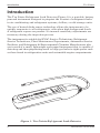
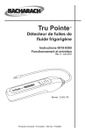
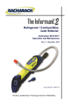
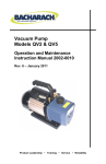
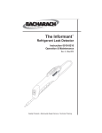
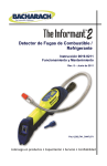
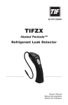
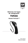
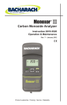
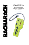
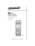
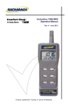
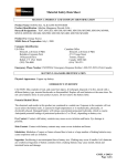
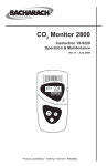
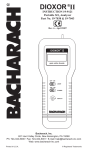
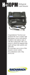
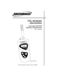
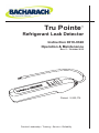
Tru Pointe ™ Refrigerant Leak Detector Instruction 0019-9328 Operation & Maintenance Rev. 5 – October 2012 Patent: 5,932,176 Product Leadership • Training • Service • Reliability Tru Pointe b Instruction 0019-9328 Tru Pointe COMBUSTIBLE REFRIGERANT GAS WARNING: For your safety, DO NOT use the Tru Pointe refrigerant leak detector to detect refrigerants which are rated as combustible/flammable gases (e.g. ASHRAE - A2 or A3 rated refrigerants). Use with combustible/flammable refrigerant gases can cause an explosion resulting in death or severe injury. WARRANTY Bacharach, Inc. warrants to Buyer that at the time of delivery this Product will be free from defects in material and manufacture and will conform substantially to Bacharach Inc.’s applicable specifications. Bacharach’s liability and Buyer’s remedy under this warranty are limited to the repair or replacement, at Bacharach’s option, of this Product or parts thereof returned to Seller at the factory of manufacture and shown to Bacharach Inc.’s reasonable satisfaction to have been defective; provided that written notice of the defect shall have been given by Buyer to Bacharach Inc. within one (1) year after the date of delivery of this Product by Bacharach, Inc. Bacharach, Inc. warrants to Buyer that it will convey good title to this Product. Bacharach’s liability and Buyer’s remedy under this warranty of title are limited to the removal of any title defects or, at the election of Bacharach, to the replacement of this Product or parts thereof that are defective in title. THE FOREGOING WARRANTIES ARE EXCLUSIVE AND ARE GIVEN AND ACCEPTED IN LIEU OF (I) ANY AND ALL OTHER WARRANTIES, EXPRESS OR IMPLIED, INCLUDING WITHOUT LIMITATION THE IMPLIED WARRANTIES OF MERCHANTABILITY AND FITNESS FOR A PARTICULAR PURPOSE: AND (II) ANY OBLIGATION, LIABILITY, RIGHT, CLAIM OR REMEDY IN CONTRACT OR TORT, WHETHER OR NOT ARISING FROM BACHARACH’S NEGLIGENCE, ACTUAL OR IMPLIED. The remedies of the Buyer shall be limited to those provided herein to the exclusion of any and all other remedies including, without limitation incidental or consequential damages. No agreement varying or extending the foregoing warranties, remedies or this limitation will be binding upon Bacharach, Inc. unless in writing, signed by a duly authorized officer of Bacharach. NOTICE Product improvements and enhancements are continuous, therefore the specifications and information contained in this document may change without notice. Bacharach, Inc. shall not be liable for errors contained herein or for incidental or consequential damages in connection with the furnishing, performance, or use of this material. No part of this document may be photocopied, reproduced, or translated to another language without the prior written consent of Bacharach, Inc. Copyright © 2003-2011, Bacharach, Inc., all rights reserved. BACHARACH and Tru Pointe are registered trademarks of Bacharach, Inc. All other trademarks, trade names, service marks and logos referenced herein belong to their respective companies. Instruction 0019-9328 c Tru Pointe d Instruction 0019-9328 Tru Pointe Contents Contents Introduction..................................................................................................2 Features..........................................................................................................3 Technical Characteristics..........................................................................4 Operation.......................................................................................................6 Battery Installation.............................................................................6 Turning the Instrument ON / OFF..................................................... 7 Low Battery Indication........................................................................8 Selecting High / Low Sensitivity Mode............................................... 8 Procedure for Locating a Refrigerant Leak........................................ 8 Sensor Failure Indication....................................................................9 False Refrigerant Indication.............................................................10 SAE Leak Detection Tips..................................................................10 Maintenance................................................................................................12 Routine Maintenance........................................................................12 Sensor Replacement..........................................................................13 Troubleshooting Guide.............................................................................14 Parts & Service...........................................................................................16 Replacement Parts.............................................................................16 Sales/Service Centers........................................................................16 Declaration of Conformity.......................................................................17 Instruction 0019-9328 1 Tru Pointe Introduction Introduction The Tru Pointe Refrigerant Leak Detector (Figure 1) is a portable, battery powered instrument designed to pinpoint the location of refrigerant leaks in air conditioning and refrigerant systems, chillers, or cold storage units. The use of heated-diode sensor technology allows the instrument to be quickly responsive to all refrigerants, even when high background levels of refrigerant vapors are present. No manual sensitivity adjustments are necessary during the inspection process. The instrument is suitable for HVAC Service Technicians, Refrigerant Service Technicians, Plant Maintenance Departments, Automotive Service Facilities, and Refrigerant & Environmental Chamber Manufactures who are in need of a small, lightweight and rugged instrument that is capable of detecting and then pinpointing small to large gas leaks in tight spaces such as those found in refrigeration units and automobile engine compartments. Figure 1. Tru Pointe Refrigerant Leak Detector 2 Instruction 0019-9328 Tru Pointe Introduction Features •Quickly pinpoints the location of refrigerant leaks •Patented heated-diode sensor that represents the latest advancements in sensor t echnology •Patented microprocessor-controlled circuitry •High and low-sensitivity modes, push button selectable •Automatic zero and background compensation that allows a leak to be quickly found in contaminated atmospheres without requiring manual sensitivity adjustments •Flexible probe 14 inches (356 mm) in length for locating leaks in hard-to-reach areas •One-handed operation •No user calibration required •Long life, DC brushless fan provides positive airflow past sensor r esulting in a faster response time •Batteries included •One year warranty •Extended warranty available Instruction 0019-9328 3 Tru Pointe Technical Characteristics Technical Characteristics Power������������������������������������������ Two ‘D’ Alkaline Batteries Warm-Up Time�������������������������� 10 seconds Refrigerants Detected���������������� All CFC, HCFC and HFC refrigerants including: R-12, R-22, R-123, R-134a and blends R-404A, R-408A, R-409A, and R-410A Sensor: Type����������������������������������������� Heated Diode, Dispersive Electron, Plug-In Life Expectancy*��������������������� Typically 150 hours or 1 year of normal use Battery Life�������������������������������� 11 hours min. high sensitivity mode, 20 hours min. low sensitivity mode, as tested using Duracell Ultra MX1300 alkaline batteries Response Time��������������������������� Instantaneous Sensitivity���������������������������������� The instrument will detect a leak of at least 0.5 oz/year (14 g/yr) as detected by moving probe tip at 2" (50 mm) per second, 0.2" (5 mm) above leak source. A leak rate of less than 0.1 oz/year (3 g/yr) can be detected when probe tip is held steady over leak source for at least 5 seconds. Sensitivity Adjustment�������������� Automatic Weight ���������������������������������������� 1.16 lb (0.53 kg) w/ batteries Size (excluding probe) ��������������� 2.12W x 9.5L x 2.4H inches (53.8 x 241.3 x 61.0 mm) Probe Length������������������������������ 14" (356 mm) * Caution: Exposing the sensor to a steady stream of highly concentrated refrigerant will severely reduce sensor life or damage the sensor. Sensor life is directly proportional to the amount of refrigerant that passes through the sensor. 4 Instruction 0019-9328 Tru Pointe Technical Characteristics Operating Environment: Position������������������������������������ Any Temperature��������������������������� 32 to 122 °F (0 to 50 °C) Humidity��������������������������������� 10 to 90% RH, non-condensing Approvals������������������������������������ Certified to SAE J1627 CE Mark: Independently tested in accordance with EMC Directive 2004/108/EC Instruction 0019-9328 5 Tru Pointe Operation Operation Battery Installation 1. Remove battery cover by pressing down on the battery cover tab, and then sliding the cover off the instrument. See Figure 2. 2. Install two ‘D’ alkaline batteries into the battery compartment, observing the polarity markings that are molded inside of the case. 3. Slide the battery cover back onto the instrument until its tab clicks into place. Figure 2. Battery Installation 6 Instruction 0019-9328 Tru Pointe Operation Turning the Instrument ON / OFF See Figure 3. The instrument is toggled ON and OFF by pressing the on/off button. When the instrument is first turned ON, observe that the green power on LED will glow, and that the red leak rate LED flashes rapidly along with the audible indicator producing a rapid ticking sound or constant tone. The instrument requires a minimum of 10 seconds to warm up. After which time both the leak rate LED and audible indicator should slow down to no more than 1 or 2 flashes/ticks per second. Note that during the warm-up period, the instrument has zeroed out any background concentration of refrigerant vapors that may have been present in the area. After the instrument is turned ON and allowed to warm up, it is ready to perform leak testing as described in Section Procedure for Locating a Refrigerant Leak. Red LED: Flash rate increases when the instrument detects an increased level of refrigerant Amber LED: ON = High Sensitivity OFF = Low Sensitivity Blinking = Sensor Failure Green LED: ON = Instrument turned ON Blinking = Low battery condition Press to toggle instrument ON and OFF Press to toggle between high and low sensitivity Figure 3. Indicators and Controls Instruction 0019-9328 7 Tru Pointe Operation Low Battery Indication A low-battery condition is indicated when the green power on LED begins to flash. Approximately 20 minutes of operation time remains from the time this LED first begins to flash; after which, the instrument’s operation will gradually become erratic. When a low-battery indication occurs, replace the batteries as described under the previous Section Battery Installation. Selecting High / Low Sensitivity Mode When the Tru Pointe is first turned ON it defaults to its low-sensitivity mode. Place the instrument into its high-sensitivity mode by pressing the high/ low sensitivity button until the high sensitivity LED turns ON (high sensitivity amber LED glows). Tip: Use the low-sensitivity mode to extend battery and sensor life. Use the high-sensitivity mode, if necessary, to pinpoint leaks. Return the instrument to its low-sensitivity mode by pressing the high/ low sensitivity button until the high sensitivity LED turns OFF. Procedure for Locating a Refrigerant Leak Important: The instrument’s function is to detect a change in refrigerant level, and not to make a quantitative measurements. The technique of locating a leak by detecting a change in level allows an operator to quickly locate the source of a leak without making manual sensitivity adjustments, or being concerned about the background refrigerant level in the surrounding area. Begin by slowly moving the probe tip toward the area of the suspected leak source. If surfaces are dirty or wet, wipe them off with a shop towel. Avoid allowing dirt to clog the probe tip, or allowing water to enter the instrument. 8 Instruction 0019-9328 Tru Pointe Operation When the instrument first detects an increase in the refrigerant level, the leak rate LED begins flashing and the audible indicator begins ticking at a faster rate. If movement of the probe is stopped for more than 10 seconds, the instrument will self-zero and return to its idle state even though refrigerant is still present. Once the presence of refrigerant has been determined and the instrument allowed to self-zero, moving the probe toward the leak source will once again cause the instrument to respond in a positive manner. The instrument’s audible and visual indications will fall if the probe is moved away from the leak source. Caution: Exposing the sensor to a steady stream of highly concentrated refrigerant will severely reduce sensor life or damage the sensor. Sensor life is directly proportional to the amount of refrigerant that passes through the sensor. Use the following general procedure to pinpoint the source of a leak: 1. Move the probe tip along the refrigerant lines and around the fittings until the leak rate LED begins flashing and the audible indicator starts ticking at a faster rate. 2. Continue moving the probe tip in a direction that keeps the instrument responding in a positive manner. 3. Once the source of the leak has been passed, the instrument’s visual and audible indications will fall. At this point, reverse the direction of probing so that the instrument once again responds in a positive manner. 4. Repeat Step 3 until a small movement of the probe tip over the leak source results in the rapid indication of increasing and decreasing refrigerant levels. Sensor Failure Indication A failed sensor is indicated when the high sensitivity LED begins to flash. Refer to the Troubleshooting Guide Section of this manual for information on how to remedy this condition. Instruction 0019-9328 9 Operation Tru Pointe False Refrigerant Indication False refrigerant indications are usually caused by abnormal changes in sensor temperature. These temperature changes are typically due to a sudden change in air flow past the sensor, or the sensor being heated or cooled by an outside source. To avoid false refrigerant indications, DO NOT . . . •allow the probe tip to become clogged with dirt, • allow the probe to suck in hot gases. SAE Leak Detection Tips The following was derived from SAE Surface Vehicle Standard J1628, Technician Procedure for Using Electronic Refrigerant Leak Detectors for Service of Mobile Air-Conditioning Systems: •The electronic leak detector shall be operated in accordance with the equipment manufacturer’s operating instructions. •Leak test with the engine not in operation. •The air conditioning system shall be charged with sufficient refrigerant to have a gauge pressure of at least 340 kPa (49 psi) when not in operation. At temperatures below 15 °C (59 °F), leaks may not be measurable, since this pressure may not be reached. •Take care not to contaminate the detector probe tip if the part being tested is contaminated. If the part is particularly dirty, it should be wiped off with a dry shop towel or blown off with shop air. No cleaners or solvents shall be used, since many electronic detectors are sensitive to their ingredients. •Visually trace the entire refrigerant system, and look for signs of airconditioning lubricant leakage, damage, and corrosion on all lines, hoses, and components. Each questionable area shall be carefully checked with the detector probe, as well as all fittings, hose-to-line couplings, refrigerant controls, service ports with caps in place, brazed or welded areas, and areas around attachment points and hold-downs on lines and components. 10 Instruction 0019-9328 Tru Pointe Operation •Always follow the refrigerant system around in a continuous path so that no areas of potential leaks are missed. If a leak is found, always continue to test the remainder of the system. •At each area checked, the probe shall be moved around the location, at a rate no more than 25 to 50 mm/sec (1 to 2 in./sec), and no more than 5 mm (0.2 inch) from the surface completely around the position. Slower and closer movement of the probe greatly improves the likelihood of finding a leak. •An apparent leak shall be verified at least once by blowing shop air into the area of the suspected leak, if necessary, and repeating the check of the area. In cases of very large leaks, blowing out the area with shop air often helps locate the exact position of the leak. •Leak testing of the evaporator core while in the air conditioning module shall be accomplished by turning the air conditioning blower on high for a period of 15 seconds minimum, shutting it off, then waiting an additional 15 seconds minimum for the refrigerant to accumulate in the case, then inserting the leak detector probe into the blower resistor block or condensate drain hole if no water is present, or into the closest opening in the heating/ventilation/air conditioning case to the evaporator, such as the heater duct or a vent duct. If the detector activates, a leak apparently has been found. •Following any service to the refrigerant system of the vehicle, and any other service which disturbs the refrigerant system, a leak test of the repair and of the service ports of the refrigerant system shall be done. Instruction 0019-9328 11 Maintenance Tru Pointe Maintenance By following the procedures outlined below, The Tru Pointe will provide many years of trouble-free and dependable operation. Routine Maintenance •Replace the batteries per Section Battery Installation when the green power on LED begins to flash. •Periodically check the instrument’s sensitivity by exposing it to a source of refrigerant gas. DO NOT check sensitivity by cracking open a bottle of refrigerant or Schrader valve and exposing the sensor to a stream of pure refrigerant. This will severely reduce sensor life or damage the sensor. •Keep the instrument case and probe clean by wiping them with a shop towel. If necessary, moisten the towel with a mild detergent solution. Avoid using any type of solvents that may either attack the instrument’s ABS plastic case, or leave behind a hydrocarbon residue that may desensitize the sensor. 12 Instruction 0019-9328 Tru Pointe Maintenance Sensor Replacement Over time the sensor will become less responsive to refrigerant gas as it nears the end of its useful life. A sensor’s average life expectancy is approximately 150 hours or 1 year of normal use, but will vary depending on the amount of refrigerant that passes through the sensor. Replace the sensor as follows (see Figure 4): Material Required: •Sensor (refer to Section Replacement Parts) Procedure: 1. Turn OFF instrument. 2. Grasp nose cone of probe assembly and pull probe away from case using a slight twisting motion. 3.Sensor may be hot! Pull spent sensor from its socket and discard. 4. Plug in new sensor. 5. Push probe assembly back into case. 6. Turn ON the instrument and check that it responds in a positive manner to a source of refrigerant gas. Grasp probe assembly’s nose cone and pull probe away from case while applying a slight twisting motion. REFRIGERANT SENSOR Figure 4. Sensor Replacement Instruction 0019-9328 13 Tru Pointe Troubleshooting Troubleshooting Guide The following table lists the causes and remedies for the most common problems that may occur with the instrument. If the information in Table 1 does not solve the problem, or for help with any problem that is not listed, please contact one of the Bacharach Sales/ Service Centers listed in Section Parts & Service. TABLE 1. TROUBLESHOOTING GUIDE Symptom Instrument does not turn ON. Probable Cause & Remedy a.Batteries are dead or installed backward. Install two fresh ‘D’ alkaline batteries per Section Battery Installation. b. Faulty refrigerant sensor. Remove sensor and turn ON instrument. If instrument now operates, replace sensor per Section Sensor Replacement. The power on LED is flashing. Low battery indication. Replace batteries per Section Battery Installation. The high sensitivity LED is flashing in clean air. a.Sensor depleted or faulty. Replace sensor per Section Sensor Replacement. b. Batteries are nearly depleted. Replace per Section Battery Installation. The leak rate LED is turned on steady, and the audible indicator is producing a steady tone. a. This is normal during warm up. After warm up the flash/tick rate should slow down to less than 1 or 2 times per second. Instrument does not respond to the presence of refrigerant. a.Sensor nearly depleted or faulty. Replace sensor per Section Sensor Replacement. b. Probe tip clogged, not allowing air to flow over sensor. Unclog probe tip. b. Probe assembly loose. Push nose cone of probe assembly back into instrument. c. Probe tip clogged, not allowing air to flow over sensor. Unclog probe tip. d.Crack in rubber sheathing that covers the probe’s flexible tube, allowing air to enter through the crack. Replace probe assembly. 14 Instruction 0019-9328 Tru Pointe Troubleshooting TABLE 1. TROUBLESHOOTING GUIDE (Cont.) Symptom Probable Cause & Remedy Short sensor life. Senor has often been exposed to high levels of refrigerant. Avoid exposing sensor to pure refrigerant for long periods of time. Erratic refrigerant leak indication. a.Windy conditions. Shut off surrounding fans; protect probe tip from wind; switch to low-sensitivity mode per Section High/Low Sensitivity Mode. b. Probe assembly loose. Push nose cone of probe assembly back into instrument. c. Low batteries. Replace batteries per Section Battery Installation. d.Loose sensor. Remove probe and ensure that the sensor is being held firmly in its socket (see Figure 4.) e. Sensor faulty. Replace sensor per Section Sensor Replacement. Instruction 0019-9328 15 Parts & Service Tru Pointe Parts & Service Complete Kit: Includes detector, instruction manual, 2 ‘D’ batteries, and a hard carrying case.........................................0019-8106 Replacement Parts Battery Door..................................................................................... 0019-0548 Hard Carrying Case........................................................................ 0019-0501 Probe Assembly................................................................................ 0019-0553 Screw, Case, #4-20 x 1" Self Tapping .............................................. 0102-1982 Sensor............................................................................................... 0019-0559 Sales/Service Centers United States Pennsylvania 621 Hunt Valley Circle New Kensington, PA 15068 Phone: 1-800-736-4666 Fax: 724-334-5723 Email: [email protected] Canada Bacharach of Canada, Inc. 20 Amber St. Unit# 7 Markham, Ontario L3R SP4 Canada Phone: 905-470-8985 Fax: 905-470-8963 Email: [email protected] 16 Instruction 0019-9328 Tru Pointe Instruction 0019-9328 17 Tru Pointe 18 Instruction 0019-9328 Warranty Registration Please fill out the following information and FAX to Bacharach's Warranty Department at 724-334-5001. Or register online at www. mybacharach.com/warranty-registration.htm Name Title Company # of Employees City State Zip Phone Fax E-mail Product Purchased Part No. Serial No. Date Purchased Purchased From Address 1. What can Bacharach do to better serve you? ____________________________ __________________________________________________________________ 2. My Application: Combustion Analysis Leak Detection Appliance Service Indoor Air Quality Emission Monitoring Other (Please Specify)______________________________________________ 3. Future Applications May Include/Please Send More Information About: Combustion and IAQ Analyzers Training Programs Emissions Monitors Service Programs Refrigeration Products World Headquarters 621 Hunt Valley Circle, New Kensington, PA 15068-7074 Ph: 724-334-5000 • Fax: 724-334-5001 • Toll Free: 1-800-736-4666 Web site: www.mybacharach.com • E-mail: [email protected] Printed in U.S.A.