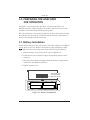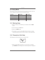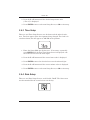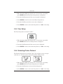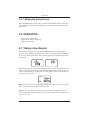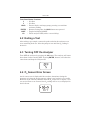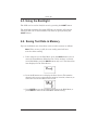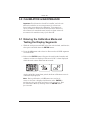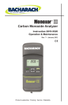
1
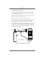
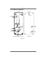
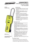
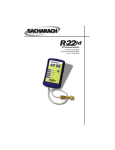
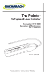
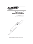
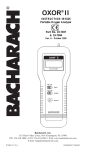
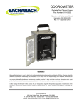
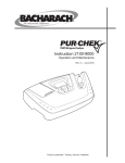
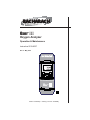
Oxor III
®
Oxygen Analyzer
Operation & Maintenance
Instruction 0019-9337
Rev. 2 - May 2010
AMBIENT
ENTER
LIGHT
HOLD
I/O
Product Leadership • Training • Service • Reliability
WARRANTY
Bacharach, Inc. warrants to Buyer that at the time of delivery this Product will be free from defects in material
and manufacture and will conform substantially to Bacharach Inc.’s applicable specifications. Bacharach’s
liability and Buyer’s remedy under this warranty are limited to the repair or replacement, at Bacharach’s option,
of this Product or parts thereof returned to Seller at the factory of manufacture and shown to Bacharach Inc.’s
reasonable satisfaction to have been defective; provided that written notice of the defect shall have been given
by Buyer to Bacharach Inc. within two (2) years after the date of delivery of this Product by Bacharach, Inc.
Bacharach, Inc. warrants to Buyer that it will convey good title to this Product. Bacharach’s liability and Buyer’s
remedy under this warranty of title are limited to the removal of any title defects or, at the election of Bacharach,
to the replacement of this Product or parts thereof that are defective in title.
All expendable items, such as electromechanical sensors, are warranted for a period of one year.
THE FOREGOING WARRANTIES ARE EXCLUSIVE AND ARE GIVEN AND ACCEPTED IN LIEU OF (I) ANY
AND ALL OTHER WARRANTIES, EXPRESS OR IMPLIED, INCLUDING WITHOUT LIMITATION THE IMPLIED WARRANTIES OF MERCHANTABILITY AND FITNESS FOR A PARTICULAR PURPOSE: AND (II) ANY
OBLIGATION, LIABILITY, RIGHT, CLAIM OR REMEDY IN CONTRACT OR TORT, WHETHER OR NOT ARISING FROM BACHARACH’S NEGLIGENCE, ACTUAL OR IMPLIED. The remedies of the Buyer shall be limited
to those provided herein to the exclusion of any and all other remedies including, without limitation incidental or
consequential damages. No agreement varying or extending the foregoing warranties, remedies or this limitation will be binding upon Bacharach, Inc. unless in writing, signed by a duly authorized officer of Bacharach.
Register your warranty by visiting
www.mybacharach.com
Declaration of Conformity
Manufacturer’s name:
Bacharach, Inc.
Manufacturer’ address:
621 Hunt Valley Circle
New Kensington, PA 15068
Product name:
Oxor™ III
conforms to the following specifications:
European Directive 89/336/EEC
EN50082-1: 1997 (Electrostatic Discharge)
EN50082-1: 1997 (Immunity)
EN55022; Group 1, Class B (Emission)
Notice:
Product improvements and enhancements are continuous, therefore the specifications and information contained in this document may change without notice.
Bacharach, Inc. shall not be liable for errors contained herein or for incidental or consequential damages in connection with the furnishing, performance, or use of this material.
No part of this document may be photocopied, reproduced, or translated to another language without the prior
written consent of Bacharach, Inc.
Copyright © 2002–2010, Bacharach, Inc., all rights reserved.
BACHARACH® and Oxor™ are trademarks of Bacharach, Inc. All other trademarks, trade names, service
marks and logos referenced herein belong to their respective companies.
A
Instruction 0019-9337
Oxor® III
Contents
1.0 INTRODUCTION ....................................................................................... 1
2.0 TECHNICAL CHARACTERISTICS .......................................................... 2
3.0 PREPARING THE ANALYZER FOR OPERATION .................................. 3
3.1 Battery Installation ............................................................................. 3
3.2 Probe Installation ............................................................................... 4
3.3 Front Panel Pushbuttons ................................................................... 5
3.4 Setup Mode ....................................................................................... 6
3.4.1 Entering Setup ........................................................................ 6
3.4.2 Temperature Units Setup ........................................................ 6
3.4.3 Time Setup .............................................................................. 7
3.4.4 Date Setup .............................................................................. 7
3.4.5 Year Setup .............................................................................. 8
3.4.6 Selecting Printer Protocol ....................................................... 8
3.4.7 Exiting the Setup Screen ........................................................ 9
4.0 OPERATION ............................................................................................. 9
4.1 Taking a Gas Sample ........................................................................ 9
4.2 Ending a Test ................................................................................... 10
4.3 Turning OFF the Analyzer................................................................ 10
4.4 O2 Sensor Error Screen ................................................................... 10
4.5 Using the Backlight .......................................................................... 11
4.6 Saving Test Data in Memory ............................................................ 11
4.7 Opening and Viewing Saved Test Data ........................................... 12
4.8 Printing Test Data ............................................................................ 12
4.9 Clearing Saved Test Data................................................................ 14
4.10 Resetting the Microprocessor ........................................................ 14
5.0 CALIBRATION & MAINTENANCE ......................................................... 15
5.1 Entering the Calibration Mode & Testing the Display Segments ..... 15
5.2 Ambient Temperature Calibration .................................................... 16
5.3 O2 Sensor Zero ............................................................................... 16
5.4 O2 Sensor Replacement .................................................................. 18
5.5 Pump Assembly Replacement......................................................... 19
6.0 PARTS & SERVICE ................................................................................ 21
6.1 Replacement Parts .......................................................................... 21
6.2 Accessories ..................................................................................... 21
6.3 Service Centers ............................................................................... 22
Instruction 0019-9337
i
Oxor® III
Notes
ii
Instruction 0019-9337
Oxor® III
1.0 INTRODUCTION
The Oxor® III is a portable analyzer designed to detect and display concentrations of Oxygen (O2) gas between 0 and 20.9%. The analyzer is capable
of testing for O2 in both ambient room air, and in the flue-gas stream of
fossil-fuel fired furnaces and boilers (with optional probe assembly).
Ordering Information:
Part No.
Description
0019-8112 Oxor III includes 4 ‘AA’ batteries, probe & hose assembly with
integral filter, and a hard carrying case.
0019-8113 Oxor III includes 4 ‘AA’ batteries, probe & hose assembly with
integral filter, hard carrying case, plus an IrDA printer.
The analyzer detects and displays the presence of O2 by first drawing in a
gas sample from the area being tested by the analyzer’s built-in motorized
pump. The gas sample is next directed into a sensor chamber where the
sample is analyzed for the presence of O2.
A permanent record of the detected O2 level, along with the current time
and date, can be made by using the optional wireless IrDA printer.
A backlight enables the operator to read the display in dimly-lit areas. A
power-saver feature causes the backlight to automatically turn OFF after
10 minutes, and causes the analyzer to shut OFF after 20 minutes of inactivity.
Instruction 0019-9337
1
Oxor® III
2.0 TECHNICAL CHARACTERISTICS
O2 Display Range ....................... 0–20.9%
O2 Accuracy ................................ +0.4 / -0.8% O2
O2 Resolution .............................. 0.1%
O2 Response Time ...................... 90% of final value within 30 sec.
Ambient Temperature Display Range.. 0 to 100° C (32 to 212° F)
Ambient Temperature Accuracy ... ±3 ° C between 0 and 40° C (32 to 104° F)
Ambient Temperature Resolution ... 0.1° C (0.1° F)
Battery Requirement ................. Four disposable ‘AA’ Alkaline batteries
Operating Time .......................... Up to 18 hours continuous (pump running
and backlight off)
Warm Up Time ........................... 60 seconds
Display ........................................ 4 digit by 2 line, 7-segment Liquid Crystal
Display
Front Panel Controls .................. Six push button switches
(refer to Section 3.3)
Operating Temperature Range .. 0 to 40° C (32 to 104° F)
Humidity ..................................... 15 to 90% RH (non-condensing)
Printer Port ................................ IrDA or HP protocol
Weight ......................................... 16 oz with batteries
Size.............................................. 7.5"H x 3.1"W x 2.1"D (190x79x53 mm)
2
Instruction 0019-9337
Oxor® III
3.0 PREPARING THE ANALYZER
FOR OPERATION
To prepare a new analyzer for operation, you must install four ‘AA’
Alkaline batteries, install the probe (if needed), and set the correct time
and date as described in the following paragraphs.
For your convenience, and to ensure that the analyzer will provide reliable
O2 readings, the O2 sensor was installed and the analyzer calibrated on a
known concentration of O2 at the factory.
3.1 Battery Installation
Install fresh batteries as described below. Check the analyzer for sufficient
charge prior to each use. Replace the batteries if the low-battery symbol
appears in the lower right corner of the LCD. To install batteries:
1. Remove battery cover from back of unit (see Figure 3-1).
2. If old batteries are installed, remove and properly dispose of the
batteries.
3. Observing the polarity markings inside the battery compartment,
install four ‘AA’ Alkaline batteries.
4. Replace battery cover.
Remove battery cover
by pressing here and
sliding cover outward
Figure 3-1. Battery Installation
Instruction 0019-9337
3
Oxor® III
3.2 Probe Installation
To install the probe, simply slide its hose over the GAS inlet of the analyzer (see Figure 3-2).
Hose
Filter
Figure 3-2. Probe Connection
4
Instruction 0019-9337
Oxor® III
3.3 Front Panel Pushbuttons
Note that a push button may perform several functions, depending on what
screen is being displayed at the time.
I/O
• Turns analyzer ON/OFF. There is a 60 second warm-up and
a 5 second turn-off-delay period.
• Places the analyzer into either its Setup or Calibration Mode
when used in conjunction with the ENTER or HOLD button.
• Causes the displayed value to increase or change while in
the Calibration or Setup Mode.
• Causes the displayed value to decrease or change while in
the Calibration or Setup Mode.
ENTER
• Starts a test – pump ON.
• Sets up the analyzer to be placed into its Calibration Mode
when held down with the analyzer OFF. (Used in conjunction with the I/O button.)
• Stores the displayed value and automatically steps to the
next screen when pressed during calibration or setup.
• Displays the O2 screen when held down for 2 seconds while
in the Calibration Mode.
• Aborts turn-off and keeps the analyzer turned ON when
pressed during either the 5 second turn-off-delay period.
HOLD
• Freezes the display and stops the pump during a test.
• Starts a printout when pressed twice with the pump running, or when pressed once with the pump OFF.
• Sets up the analyzer to be placed into its Setup Mode when
held down with the analyzer OFF. (Used in conjunction with
the I/O button.)
LIGHT
Toggles the backlight ON and OFF.
Instruction 0019-9337
5
Oxor® III
3.4 Setup Mode
The analyzer is preset at the factory for the parameters shown below, but
can be changed as described in their associated sections.
Function
Parameter
To Change
Temperature Unit
°F
Section 3.4.2
Time
Not Set
Section 3.4.3
Date
Not Set
Section 3.4.4
Year
Not Set
Section 3.4.5
Printer
IrDA
Section 3.4.6
3.4.1 Entering Setup
1. With the analyzer turned OFF, press and hold down the HOLD
button.
2. Press and release the I/O button.
3. Release the HOLD button.
4. The analyzer is now in its Setup Mode. Refer to Sections 3.4.2 thru
3.4.6 for information on how to set the analyzer’s various parameters.
3.4.2 Temperature Units Setup
The Temperature Units Setup Screen is labeled “Unit”.
1. Enter the Setup Mode per Section 3.4.1. If necessary, repeatedly
press ENTER until the Temperature Units Setup Screen is displayed.
6
Instruction 0019-9337
Oxor® III
2. Press the or button until the desired temperature unit
(°F or °C) is displayed.
3. Press ENTER to move to the next Setup Screen, or I/O to exit setup.
3.4.3 Time Setup
There are two Time Setup Screens, one for hours and the other for minutes. Two bars appear above the segments being changed. The clock is in
a 24 hour format, but will appear as AM/PM on the printout.
.
1. Enter the Setup Mode per Section 3.4.1. If necessary, repeatedly
press ENTER until the first Time Setup Screen is displayed—the
one with two bars over the hour digits.
2. Press the
or
button until the correct hour value is displayed.
3. Press ENTER to move the selection bars over the minute digits.
4. Press the
or
button until the correct minute value is displayed.
5. Press ENTER to move to the next Setup Screen, or I/O to exit setup.
3.4.4 Date Setup
There are two Date Setup Screens, each labeled “DAtE”. The first screen
sets the month while the second screen sets the day.
Instruction 0019-9337
7
Oxor® III
1. Enter the Setup Mode per Section 3.4.1. If necessary, repeatedly
press ENTER until the first Date Setup Screen is displayed.
2. Press the
or
button until the correct month is displayed.
3. Press ENTER to switch to the second Date Setup Screen.
4. Press the
or
key until the correct day is displayed.
5. Press ENTER to move to the next Setup Screen, or I/O to exit setup.
3.4.5 Year Setup
The Year Setup Screen is labeled “yEAr”.
1. Enter the Setup Mode per Section 3.4.1. If necessary, repeatedly
press ENTER until the Year Setup Screen is displayed.
2. Press the
or
button until the correct year is displayed.
3. Press ENTER to move to the next Setup Screen, or I/O to exit setup.
3.4.6 Selecting Printer Protocol
The Printer Setup Screen is labeled “Prnt”. The analyzer can be set up to
send data to a wireless printer using either HP or IrDA protocol.
1. Enter the Setup Mode per Section 3.4.1. If necessary, repeatedly
press ENTER until the Printer Setup Screen is displayed.
2. Press the
or
button to select the desired protocol.
3. Press ENTER to move to the next Setup Screen, or I/O to exit setup.
8
Instruction 0019-9337
Oxor® III
3.4.7 Exiting the Setup Screen
Press the I/O button at any time to exit the Setup Mode and turn the analyzer OFF. Note that the last displayed parameter is automatically saved
in memory.
4.0 OPERATION
• Power the analyzer ON
• Wait for the unit to warm up
• Take a gas sample
4.1 Taking a Gas Sample
Turn ON the analyzer by pressing the I/O button. Observe that when
power is first applied, the software revision level is first displayed followed
by a screen that counts down the warm-up period. The warm-up period is
60 seconds.
.
Following warm-up, the O2 screen appears. This screen directly shows O2
levels in the range of 0-20.9% and ambient temperatures in the range of
0-100° C (32 to 212° F). If the probe is being used, insert the probe tip into
the area to be sampled.
AMBIENT
Note: If a sensor error was detected during warm-up, the O2 Sensor Error
Screen will be displayed. Refer to Section 4.4.
Tip: An O2 error will occur when the oxygen sensor's output drops to between 80 and 90. Consider replacing the oxygen sensor when its ouput level
drops below 100.
Instruction 0019-9337
9
Oxor® III
Front Panel Button Functions:
– No effect
– No effect
HOLD – Freezes display and stops pump; pressing a second time
activates printing
ENTER – Restarts testing after the HOLD button was pressed
LIGHT – Toggles backlight ON/OFF
I/O
– Turns analyzer OFF (with a 5 second delay)
4.2 Ending a Test
After taking a gas sample, remove the probe and take the analyzer to an
area containing fresh air. Allow the pump to run until the O2 reading is
20.9% O2.
4.3 Turning OFF the Analyzer
Turn OFF the analyzer by pressing the I/O button. The analyzer will count
down from 5 before turning OFF. Pressing ENTER, however, will abort the
count down and keep the analyzer ON.
4.4 O2 Sensor Error Screen
An O2 sensor error is displayed if the analyzer determines during the
warm-up cycle that the oxygen sensor's output is too low for it to be usable.
However, in the extreme condition when the O2 sensor has no output, a sensor error will not occur. Instead, the O2 reading will be 0.0, as displayed in
the O2 Screen.
10
Instruction 0019-9337
Oxor® III
4.5 Using the Backlight
The LCD can be read in dimly-lit areas by pressing the LIGHT button.
The backlight automatically turns OFF after 10 minutes of keyboard
inactivity, but can be turned OFF at any time by again pressing the
LIGHT button.
4.6 Saving Test Data in Memory
Up to 10 individual sets of test data can be saved in memory as follows:
Note: When memory is full, the next reading saved will overwrite the oldest reading.
1. If the analyzer is in its Run Mode, press the HOLD button twice to
enter the Print/Memory Menu Screens. If the analyzer is already
in its Hold Mode, press the HOLD button only once. The first menu
item displayed is the Print Screen.
2. Press the button once to display the Save Screen. The number
shown in this screen represents the memory location (1 thru 10) to
which the current test data will be saved.
3. Press ENTER to save the test data and return to the Hold Mode, or
press HOLD to return to the Hold Mode without saving.
Instruction 0019-9337
11
Oxor® III
4.7 Opening and Viewing Saved Test Data
Perform the following to open and view saved test data:
Note: If no test data has been saved, the option to open the
memory for viewing will not be available.
1. If the analyzer is in its Run Mode, press the HOLD button twice to
enter the Print/Memory Menu Screens. If the analyzer is already
in its Hold Mode, press the HOLD button only once. The first menu
item displayed is the Print Screen.
2. Press the or button until the Open Screen is displayed, and
then press ENTER to open the memory locations for viewing. The
number shown in the second screen represents the most recent
memory location where data was stored.
3. Press the or button to scroll to the desired memory location,
and then press ENTER to recall the stored data and return to the
Hold Mode. While in the Hold Mode, the recalled data can be viewed
or printed per Section 4.8.
4.8 Printing Test Data
Tip: To avoid printing errors, it is important to select the
correct protocol per Section 3.4.6 before saving data.
Turn ON the printer. Refer to the printer’s instruction manual for detailed
operation and maintenance information.
If not already done, set the printer parameters as follows:
• Data: 8 bits
• Parity: None
• Baud: 9600
• Handshaking: X-on/X-off
12
Instruction 0019-9337
Oxor® III
Align the printer with the top of the analyzer as shown in Figure 4-1.
in.
in
®
Figure 4-1. Printer Alignment & Sample Printout
Print Current Test Data
1. With the analyzer in its Run Mode, press the HOLD button twice to
display the Print Screen.
2. Press ENTER to start printing.
Instruction 0019-9337
13
Oxor® III
Print All Test Data
1. With the analyzer in its Run Mode, press the HOLD button twice
to display the Print Screen. Then press the button to display the
Print All Screen.
2. Press ENTER to start printing.
4.9 Clearing Saved Test Data
Clear all saved test data as follows:
Note: If no test data has been saved, the option to clear
memory will not be available.
1. With the analyzer in its Run Mode, press the HOLD button twice to
display the Print Screen.
2. Press the or button to scroll to the Clear Screen, and then press
ENTER to display the Clear All Screen.
3. Press ENTER again to clear memory and return to the Hold Mode,
or press HOLD to return to the Hold Mode without clearing memory.
4.10 Resetting the Microprocessor
If the analyzer ‘locks up’ and cannot be turned OFF, reset the microprocessor by removing one of the batteries for 5 seconds.
14
Instruction 0019-9337
Oxor® III
5.0 CALIBRATION & MAINTENANCE
Important: Fresh batteries should be installed, and the unit
allowed to stabilize at room temperature for at least two
hours before proceeding with calibration. To maintain accuracy as listed in the Technical Characteristics Section of
this manual, the standards used must be at least 4 times as
accurate as the stated accuracy of the Oxor III.
5.1 Entering the Calibration Mode and
Testing the Display Segments
1. With the analyzer turned OFF, place the unit in fresh, ambient air;
then press and hold down the ENTER button.
2. Press the I/O button and release it. Observe that all LCD segments
are turned ON.
3. Release the ENTER button. Observe the unit’s model number and
software version are displayed. The word “CAL” is then displayed
while the unit counts down from 60 seconds.
.
At the end of the count-down period, the first calibration screen is
automatically displayed.
Note: During calibration, the
buttons are used to increase or decrease a displayed calibration value. ENTER is
used to store the new value and move to the next screen. Exit
the Calibration Mode by holding down the ENTER button
for 2 seconds.
Instruction 0019-9337
15
Oxor® III
5.2 Ambient Temperature Calibration
Material Required:
Calibrated Thermometer
Procedure:
1. Enter the Calibrate Mode as described in Section 5.1. Observe that
“AMBIENT” is displayed at the top of the display; if not, repeatedly
press ENTER until it appears.
2. Use the
buttons to adjust the displayed value to match the
reading of a calibrated thermometer.
3. Press ENTER to store the displayed value and move to the next
calibration screen, or hold down ENTER for 2 seconds to store the
displayed value and display the O2 screen, or press the I/O button to
exit the Calibration Mode and turn OFF the analyzer without saving the changes.
5.3 O2 Sensor Zero
Material Required:
• Cylinder of 100% Nitrogen (P/N 9550-0049)
• Calibration Kit, (P/N 0024-7059)
Procedure:
1. With the analyzer sampling fresh air, enter the Calibration Mode as
described in Section 5.1. Then repeatedly press the ENTER button
until “O2” appears in the lower left side of the display.
2. Allow the pump to run and sample fresh air for at least 1 minute.
3. Use the
16
buttons to set the displayed value to 20.9%.
Instruction 0019-9337
Oxor® III
4. Set up the Calibration Kit with 100% N2, as described in the instructions supplied with the kit.
5. Connect the tubing of the Calibration Kit to the GAS inlet of the
analyzer; then adjust the regulator for approximately 2 SCFH of
excess flow (see Figure 5.1).
6. After the analyzer has stabilized (2 to 3 minutes), use the
tons to set the displayed value to 0.0%.
but-
7. Disconnect tubing from analyzer and turn off gas flow.
8. Allow the analyzer's pump to run until the O2 reading returns to
20.9. If necessary, use the
buttons to readjust the reading to
20.9. Repeat steps 3 though 7 to verify the zero adjustment.
9. Press ENTER to store the new calibration values and move to the
next calibration screen; Or hold down ENTER for 2 seconds to store
the new calibration values and enter the Run Mode; Or press the
I/O button to exit the Calibration Mode and turn off the analyzer
without saving the changes.
Tubing*
Regulator
Leave top
port open
“T”
connector*
Flow
meter*
Gas
Cylinder
*Contained in Calibration Kit
Gas
fitting
Figure 5-1. Calibration Kit Hookup
Instruction 0019-9337
17
Oxor® III
5.4 O2 Sensor Replacement
Material Required:
• O2 Sensor, P/N (0024-8106)
• #1 Phillips Screwdriver
Procedure:
1. Disassemble the analyzer as follows:
a. Remove the battery cover and the batteries, uncovering one of
the cover hold-down screws.
b. Remove and set aside all four cover hold-down screws.
c. With the analyzer on its back, remove the front cover, laying it
face down to the left of the body.
d. Carefully remove the circuit board, slipping off the battery connector on top, and then laying the circuit board face down in the
top cover.
2. Slip off the oxygen sensor's electrical connector from the circuit
board. Push down and twist counterclockwise. Then pull the oxygen
sensor out of its socket (see Figure 5-2).
Tip: To obtain a better grip on the oxygen sensor, it may be necessary to
remove the screw that secures the sensor socket to the case.
3. Using the old sensor as a guide, remove the paper backing from the
new sensor gasket contained in the replacement kit and adhere it
to the new sensor.
4. Properly dispose of the old oxygen sensor (see instruction sheet that
comes with the new sensor).
5. Mount the new oxygen sensor in its socket. If the sensor socket was
removed in Step 2, re-attach it to the case.
6. Plug the oxygen sensor's electric connector into the printed circuit
board (observe polarity; see Figure 5-2). Reassemble the analyzer.
Note: The sensor may take several hours to stabilize after being connected to the printed circuit board.
18
Instruction 0019-9337
Oxor® III
5.5 Pump Assembly Replacement
Material Required:
• Pump, P/N (0024-3048)
• #1 Phillips Screwdriver
Procedure:
1. Disassemble the analyzer as follows:
a. Remove the battery cover and the batteries, uncovering one of
the cover hold-down screws.
b. Remove and set aside all four cover hold-down screws.
c. With the analyzer on its back, remove the front cover, laying it
face down to the left of the body.
d. Carefully remove the circuit board, slipping off the battery connector on top, and then laying the circuit board face down in the
top cover (see Figure 5-2).
2. Slip off the pump motor’s electrical connector from the circuit
board.
3. Unscrew the pump’s hold down clamp and remove it from the pump
(see Figure 5-2). Make note of how the pump wiring is routed.
4. Make note of how the tubing connects to the pump; then carefully
remove tubing from pump.
5. Remove the old pump and discard.
6. Install the new pump and reinstall the tubing, taking care not to
pinch or crimp the tubing. Also be sure that the pump wiring is
routed as was noted in Step 3.
7. Reassemble the analyzer.
Instruction 0019-9337
19
Oxor® III
6.0 PARTS & SERVICE
CO SENSOR
GASKET
PUMP
HOLD
DOWN
CLAMP
Back Case Component Locations
PCB Locations
Figure 5-2.
20
Instruction 0019-9337
Oxor® III
6.1 Replacement Parts
Description
Part No.
Oxygen Sensor With Gasket ............................................................0024-8106
Oxygen Sensor Gasket ..................................................................... 0024-1111
Pump Assembly ............................................................................... 0024-3048
Battery Door .................................................................................... 0019-0525
Basic Probe/Hose Assembly ............................................................ 0019-3086
6.2 Accessories
STANDARD ACCESSORIES:
Battery, ‘AA’ Alkaline (Qty 4) ......................................................... 0204-0004
Instruction Manual ..........................................................................0019-9337
Hard Carrying Case........................................................................ 0024-0865
OPTIONAL ACCESSORIES:
AC Adapter (Battery Eliminator) ....................................................0024-1254
Calibration Kit .................................................................................0024-7059
Gas Cylinder, 100% N2 ................................................................... 9550-0492
Printer, Wireless IrDA ....................................................................0024-1400
Printer Paper:
1 Roll ......................................................................................... 0006-8733
5 Roll Pack ................................................................................. 0024-1310
Protective Rubber Boot w/Magnet ..................................................0024-1127
Instruction 0019-9337
21
Oxor® III
6.3 Service Centers
Replacement parts and service can be obtained by contacting one of the following Bacharach Service Centers:
United States
Bacharach, Inc.
621 Hunt Valley Circle
New Kensington, PA 15068
Phone: 724-334-5051
Fax: 724-334-5723
Email: [email protected]
Canada
Bacharach of Canada, Inc.
20 Amber St. Unit# 7
Markham, Ontario L3R SP4
Canada
Phone: 905-470-8985
Fax: 905-470-8963
Email: [email protected]
22
Instruction 0019-9337
Oxor® III
Notes:
Instruction 0019-9337
23
Oxor® III
World Headquarters
621 Hunt Valley Circle, New Kensington, PA 15068
Ph: 724-334-5000 • Fax: 724-334-5001 • Toll Free: 800-736-4666
Website: www.mybacharach.com • E-mail: [email protected]
Printed in U.S.A.
24
Instruction 0019-9337