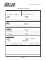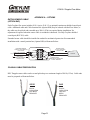
1
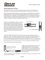
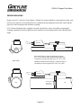
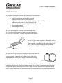
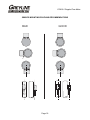
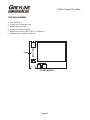
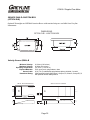
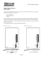
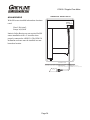
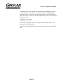
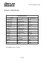
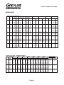
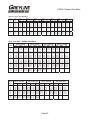
www.greyline.com USER'S GUIDE Installation & Operation Instructions Doppler Flow Meter Model DFM 5.0 Manual Series A.8.11 Note: This page has been left blank intentionally. DFM 5.0 Doppler Flow Meter INDEX CONNECTIONS ..................................................................................................... 4 KEYPAD SYSTEM ................................................................................................ 6 CALIBRATION MENU ......................................................................................... 7 MESSAGE ............................................................................................................... 8 STATUS .................................................................................................................. 8 PASSWORD............................................................................................................ 9 UNITS/MODE ....................................................................................................... 10 CALIBRATION .................................................................................................... 11 RELAY PARAMETERS....................................................................................... 12 SPECIAL FUNCTIONS ........................................................................................ 13 SENSOR MOUNTING ......................................................................................... 15 ENCLOSURE INSTALLATION .......................................................................... 19 SYNCHRONIZATION ......................................................................................... 20 FIELD TROUBLESHOOTING ............................................................................ 22 COMMON QUESTIONS AND ANSWERS ........................................................ 25 APPLICATIONS HOTLINE................................................................................. 27 PRODUCT RETURN PROCEDURE ................................................................... 28 FLOW METER DATA SHEET ............................................................................ 29 APPENDIX A – OPTIONS ................................................................................... 31 DATA LOGGING ................................................................................................. 37 SPECIFICATIONS................................................................................................ 39 APPENDIX B - CONVERSION TABLE ............................................................. 40 PIPE CHARTS ...................................................................................................... 41 IMPORTANT NOTE: This instrument is manufactured and calibrated to meet product specifications. Please read this manual carefully before installation and operation. Any unauthorized repairs or modifications may result in a suspension of the warranty. If this product is not used as specified by the manufacturer, protection may be impaired. Available in Adobe Acrobat pdf format Page 3 DFM 5.0 Doppler Flow Meter CONNECTIONS: POWER INPUT: The standard model requires AC power input between 100 to 240 VAC 50/60Hz . No adjustments are necessary for voltages within this range. Connect L (Live) N (Neutral) and AC Ground. Optional DC input model requires 9-32 VDC/9 Watts. Connect to + and - terminals. Optional Thermostat and Heater modules are available rated for 115 VAC or 230 VAC. IMPORTANT NOTE: To comply with CSA/UL electrical safety standards, AC power input and relay connection wires must have conduit entry to the instrument enclosure. Installation requires a switch, overcurrent fuse or circuit breaker in the building (in close proximity to the equipment) that is marked as the disconnect switch. ! Risk of electric shock. Loosen cover screw to access connections. Only qualified personnel should access connections. Note: Use of instrumentation over 40°C ambient requires special field wiring. Note: User replaceable fuse is 2 Amp 250V (T2AL250V). Page 4 DFM 5.0 Doppler Flow Meter RCVR GND GND TMTR CONNECTIONS NC C NO NC C NO NC C NO NC C NO EXTRA RELAYS OPTION RLY3 RLY4 RLY5 RLY6 AC POWER INPUT LN 4-20mA (1) – + RLY2 NO C NC RLY1 NO C NC L HEATER OPTION N TRANSDUCER GND AC GROUND Page 5 –+ SYNC DFM 5.0 Doppler Flow Meter KEYPAD SYSTEM The following diagram shows the DFM 5.0 menu system. Arrows show the four directions to leave a menu box. Pressing a corresponding keypad arrow will move to the next item in the direction shown. Move the cursor (underline) under numerals and increase or decrease numerals with the and keys. To store calibration values permanently (even through power interruptions), press the . Page 6 --24 hr log---------}Date Feb. 12/2010 Total 50138 USG Average 34.82 USG/m Maximum 52.20 USG/m Max Time 11:08:00 Minimum 0.000 USG/m Min Time 9:15:00 Page 7 20130.8 USG 1 2 3 4 5 6 0.000 OPTIONAL FEATURES --Status-----------}Velocity 0.00ft/s Tot 0.000USG Signal Cutoff 5% Signal Strength 0% Relays 1 2 3 4 5 6 20mA at 2500.0 USG/m Tot Relays USG/m --Message----------Data log Logging Log Used 0% Maximum 79133USG/m Sensor Good Password 0000 --Password---------- --Menu Selections---}Units / Mode Calibration Relay Parameters Data Logging Special Functions Simulation Configuration --Configuration----}Utility 1.18.13 Doppler 1.15 Logger 1.16T Relays 2 Analog Out 1 --Simulation-------}Test Actual Flow 250USG/m 4-20mA Flow 5.60mA Relays 1 2 3 4 5 6 --Special Functions}Language English Analog Out 4-20mA Backlight High Reset Totalizer NO Negative Totals NO Flo Direction NO Cal Constant 1.000 Restore Defaults No New Password 0000 --Data Logging------}Log Site ID 0 Mode Flow Set Date Feb 18/2010 Set Time 11:27:40 Interval 10sec Log Logging --Relay Parameters-}Relay 1 Function Flow Mode Pump On 1000 USG/m Off 0.000 USG/m --Calibration------}20mA at 2500.0 USG/m 4mA at 0.000 USG/m Min Vel 0.000ft/s Pipe ID 12.00in Damping 20% --Units/Mode-------}Mode Flow Linear in Volume USG Time min DFM 5.0 Doppler Flow Meter CALIBRATION MENU DFM 5.0 Doppler Flow Meter USG/m 0.000 Tot Relays 20130.8 USG 1 2 3 4 5 6 RUN The main display shows the units selected from the Units/Mode menu, Flow or Velocity rate being measured, TOTALIZER and RELAY states. The DFM 5.0 will start-up with this display and will return to this screen after a timeout if keys are not pressed in other menus. --Message----------Data log Logging Log Used 0% Maximum 79133USG/m Sensor Good MESSAGE --Status-----------}Velocity 0.00ft/s Tot 0.000USG Signal Cutoff 5% Signal Strength 0% Relays 1 2 3 4 5 6 20mA at 2500.0 USG/m STATUS Press from the RUN display to view status of the data logger and error/warning messages provided by the instrument. The word Message will appear on the RUN display if error messages are being generated by the instrument. Refer to the manual section Error/Warning Messages for a description. Press to return to the main display. Press from the RUN display to view instrument status. Velocity will be displayed in ft/sec or m/sec. Tot Displays the current totalizer reading. Signal Cutoff Adjust the setting in percent to suppress flow readings at zero flow when fluid swirling or pipe vibration may cause the instrument to continue reading. Example: Signal Cutoff at 5% will force the display and outputs to zero when signal strength drops below 5%. Signal Strength Displays percentage of signal being received by the ultrasonic sensor. Relays Energized relays will display as a white character on a black background. 20mA at Displays the flow rate set as 20mA in the Calibration menu. Press to return to the main display. Page 8 DFM 5.0 Doppler Flow Meter --24 hr log---------}Date Feb. 12/2010 Total 50138 USG Average 34.82 USG/m Maximum 52.20 USG/m Max Time 11:08:00 Minimum 0.000 USG/m Min Time 9:15:00 24 HR LOG (Data Logging option only) --Password---------- PASSWORD Password Press from the RUN display to view a formatted flow report from instruments with a built-in data logger. Press to scroll down one day or repeatedly to scroll to a specific date. Up to 365 days can be stored. Newest date will overwrite the oldest. Press to return to the main display. 0000 The password (a number from 0000 to 9999) prevents unauthorized access to the Calibration menu. From the Run display press the key to get to Password. Factory default password is 0000 and if it has not been changed press the to proceed to the Menu Selections screen. If a password is required, press to place the cursor under the first digit and or to set the number, then to the second digit, etc. Press or to proceed to the Menu Selections screen. A new password can be stored by going to Special Functions/New Password. Page 9 DFM 5.0 Doppler Flow Meter --Units/Mode-------}Mode Flow Linear in Volume USG Time min --Units/Mode-------Mode Flow }Linear in ft m mm UNITS/MODE From Mode press the and then the or to select Flow or Velocity. Flow mode displays the flow rate in engineering units (e.g. gpm, litres/sec, etc.) Press the to store your selection then the to the next menu item and to enter. From Linear press the key and then the or to select your units of measurement. Press the to store your selection. Press the key to move the symbol to each subsequent menu item and the to save your selections. Note: the volume selection "bbl" denotes U.S. oil barrel. Press or to return to the Menu Selections screen. --Units/Mode-------}Volume USG ft3 bbl L m3 IMG IG USMG --Units/Mode-------Mode Flow Linear in Volume USG }Time sec day hr min Page 10 DFM 5.0 Doppler Flow Meter --Calibration------}20mA at 2500.0 USG/m 4mA at 0.000 USG/m Min Vel 0.000ft/s Pipe ID 12.00in Damping 20% CALIBRATION Press the to Calibration and to enter. Use or to position before each menu item and to enter. When settings are completed press to store and return to the Calibration menu. 20mA at (5V Flo) Press then or to change the numbers and decimal point. Use this menu to set the corresponding flow rate that will be represented by 20mA analog output. If maximum flow is unknown, enter an estimated flow rate and observe actual flow to determine the correct maximum value. Any velocity or flow rate up to +40 ft/sec (12.2 m/sec) may be selected. 4mA at (0V Flo) Press or to set the flow rate corresponding to 4mA analog output. This setting may be left at zero flow (or velocity or can be raised to any value less than the 20mA setting, or lowered to any velocity or corresponding flow rate down to -40 ft/sec (-12.2 m/sec). Min Vel Press and enter a minimum velocity cutoff. Forward and reverse velocities less than Min Vel will be forced to zero. Pipe ID Place the cursor under the digits and then or to change the numbers and decimal point. Pipe ID should be entered as the exact inside diameter of the pipe where the sensor is mounted. Refer to the Pipe Charts Appendix in this manual for inside diameter of common pipe types and sizes. Damping Increase damping to stabilize readings under turbulent flow conditions. Decrease for fast response to small changes in flow. Damping is shown in percentage (maximum is 99%). Factory default is 20%. Press from the Units/Mode display to return to Menu Selections. Page 11 DFM 5.0 Doppler Flow Meter --Relay Parameters-}Relay 1 Function Flow Mode Pump On 1000 USG Off 0.000 USG RELAY PARAMETERS Relay Press and or to select a corresponding relay number (2 relays are standard, 4 additional are optional). Function Press or to select Off, Pulse or Flow. Flow Mode Select Pump, Low Alarm or Hi Alarm. Pump mode provides separate On/Off settings where the relay will energize at one flow rate and de-energize at another. On Position the cursor under the numerals and press or to set digits to the required relay On set point. Off set digits to the required Off set point. Low Alarm mode relay will energize at a programmable flow rate and remain energized with flow below the set point. When flow rises above the set point, the relay will de-energize. Hi Alarm mode relay will energize at a programmable flow rate and remain energized with flow above the set point. When flow falls below the set point, the relay will de-energize. Pulse Press and set digits to the flow volume increment required between relay pulses. Use this feature for remote samplers, chlorinators or totalizers. Minimum time between pulses is 2.25 seconds and pulse duration is 350 milliseconds. Return to Relay and change settings for each relay number. Press to return to Menu Selections. Page 12 DFM 5.0 Doppler Flow Meter DATA LOGGING (OPTIONAL) Refer to Options section of this manual. --Special FunctionsEnglish }Language Analog Out 4-20mA Backlight High Reset Totalizer NO Negative Totals NO Flo Direction NO Cal Constant 1.000 Restore Defaults No New Password 0000 SPECIAL FUNCTIONS Language Select English, French or Spanish Analog Out Select 4-20mA or 0-5V mode for the analog output. Backlight Select High, Medium or Low for continuous backlight. Select Key Hi/Lo for high backlight for 1 minute after a keypress and then Lo backlight until a key is pressed again. --Special FunctionsLanguage English }Backlight High Medium Low Key Hi/Lo Key High Key Med Key Low Off Select Key High, Med or Low for backlight for 1 minute after a keypress and then backlight off until a key is pressed again. Reset Totalizer Press and select Yes to erase and restart the totalizer at zero. Negative Totals Select Yes to have reverse flow readings deducted from the totalizer. Select No to totalize forward flow only and ignore reverse flow. Flo Direction Select On to enable flow direction measurement. Select Off to disable flow direction measurement. Select Invert to invert the sense of the flow measurement. Cal Constant Set to 1.000 for SE4-A transducer and QZ02L. Restore Defaults Select Yes and press to erase all user settings and return the instrument to factory default settings. New Password Select any number from 0000 to 9999 and press . Default setting of 0000 will allow direct access to the calibration menus. Setting of any password greater than 0000 will require the password to be entered to access the calibration menus. Press to return to Menu Selections. Page 13 DFM 5.0 Doppler Flow Meter --Simulation-------}Test Actual Flow 250USG/m 4-20mA Flow 5.60mA Relays 1 2 3 4 5 6 SIMULATION Exercises the 4-20mA (0-5V) output, digital display and control relays. Test Select Maximum and press to simulate maximum Flow or Velocity and to output 20mA (5V) to the analog channel. Select Minimum and press to simulate minimum Flow or Velocity and to output 4mA (0V) to the analog channel. To simulate measurements between minimum and maximum set Test to Actual and then enter for the flow measurement. The analog output and control relays will respond to the simulated value. Page 14 DFM 5.0 Doppler Flow Meter SENSOR MOUNTING LOCATION The position of the sensor is one of the most important considerations for accurate Doppler flow measurement. The same location guidelines apply to Doppler as most other types of flow meters. Before permanently mounting a Doppler sensor onsite testing is recommended to determine optimum mounting position. Use the sensor coupling compound (supplied with each Greyline flow meter, or petroleum gel, acoustic compound or electrocardiograph gel). Take several readings around the axis of the pipe and then at several points upstream and downstream from the selected position, checking for consistent readings. Avoid high or low reading areas. Mount the sensor where consistent (average) readings were obtained or continue testing on another pipe section. VERTICAL OR HORIZONTAL PIPE - Vertical pipe runs generally provide evenly distributed flow. On Horizontal pipes and liquids with high concentrations of gas or solids, the sensor should be mounted on the side (3 or 9 o’clock position) to avoid concentrations of gas at the top of the pipe, or solids at the bottom. For liquids with minimal gas bubbles (e.g. potable water) the sensor should be mounted on the top of a horizontal pipe (12 o’clock position) to obtain the best signal strength. 12 O'CLOCK POSITION WITH LOW GAS CONTENT 3 O'CLOCK POSITION WITH HIGH GAS OR SOLIDS CONTENT VERTICAL PIPE USUALLY HAS EVENLY DISTRIBUTED FLOW VELOCITY INCREASING DEVICES: Generally the sensor must be mounted away from flow disturbances such as valves, pumps, orifice plates, venturis or pipe inlets and discharges which tend to increase flow velocity. Velocity increasing devices often cause cavitation, or rapid release of gas bubbles, and readings both up and downstream may show much higher velocity. As a guideline, mount the sensor at least 20 diameters upstream or 30 diameters downstream from velocity increasing devices. Required distance from a velocity increasing device will vary in applications depending on the flow velocity and the characteristics of the liquid itself. SENSOR MOUNTS 6 DIAMETERS UPSTREAM OR 10 DOWNSTREAM FROM AN ELBOW FLOW TURBULENCE INCREASING DEVICES: Elbows, flanged connections and tees tend to introduce desirable conditions of an evenly distributed flow profile with some air or gases entrained in the flow. Sensor mounting 6 pipe diameters upstream and 10 diameters downstream from these disturbances is generally optimum. The sensor is designed to mount longitudinally on a straight section of pipe. Do not attempt to mount it on bends, elbows or fittings. Page 15 DFM 5.0 Doppler Flow Meter SENSOR MOUNTING Prepare an area 2" wide by 4" long (50mm x 100mm) for sensor bonding by removing loose paint, scale and rust. The objective of site preparation is to eliminate any discontinuity between the sensor and the pipe wall, which would prevent acoustical coupling. A PC4 Sensor Mounting Kit is supplied with each Greyline flow meter. It includes recommended coupling compound in a plastic applicator and a stainless steel mounting bracket with adjustable pipe straps. SENSOR PIPE PIPE Mount the PC4 pipe clamp as illustrated on pipes 0.6" / 15 mm OD or larger. Stainless steel bands are included for mounting on pipes up to 32" / 81 cm OD. END VIEW Additional stainless steel bands (by customer) may be combined to mount on pipes up to 180" / 4.5 m OD. SENSOR ADJUSTABLE STAINLESS STEEL STRAP PIPE Page 16 PIPE DFM 5.0 Doppler Flow Meter SENSOR COUPLING For permanent or temporary bonding, the following are recommended: a) Dow Corning silicon compound #4 (supplied) Additional supply: order Greyline Option CC b) High Temperature compound (supplied with Sensor Option SE3H) Additional supply: order Greyline Option AP-1W c) Water-based sonic compound: Order Greyline Option CC30 d) Electrocardiograph gel e) Petroleum gel (Vaseline) The above are arranged in their order of preferred application. d & e are only good for temporary bonding at room temperature. DO NOT USE: Silicon RTV caulking compound (silicon rubber). UN PO M CO SENSOR D Use the PC4 pipe clamp (supplied) as illustrated above or use a loop of electrical tape for temporary mounting. Apply silicon coupling compound #4 to the coloured face of the sensor. A bead, similar to toothpaste on a toothbrush, is ideal. Do not overtighten (crush the sensor). The sensor must be fixed securely to the pipe with coupling material between the sensor face and the pipe. Sensor installation with excessive coupling compound can result in gaps or voids in the coupling and cause errors or loss of signal. Insufficient coupling compound will create similar conditions. COMPOUND SENSOR PIPE TAPE OR CLAMP Over time temporary coupling compounds (e.g. Petroleum Gel) may gradually sag away from the sensor resulting in reduced signal strength and finally complete loss of signal. Warm temperatures, moisture and vibration will accelerate this process. Dow Corning Silicone Compound #4 as supplied with the DFM 5.0 (and available from Greyline Instruments) is recommended for semi-permanent installations. Page 17 DFM 5.0 Doppler Flow Meter SENSOR MOUNTING/COUPLING RECOMMENDATIONS GOOD BAD Page 18 DFM 5.0 Doppler Flow Meter ENCLOSURE INSTALLATION Locate the enclosure within 20 ft (6 m) of the sensor (500 ft -150 m optional). The enclosure can be wall mounted with the four mounting screws (included) or panel mounted with Option PM Panel Mount kit from Greyline Instruments. Avoid mounting the enclosure in direct sunlight to protect the electronics from damage due to overheating and condensate. In high humidity atmospheres, or where temperatures fall below freezing, Option TH Enclosure Heater and Thermostat is recommended. Seal conduit entries to prevent moisture from entering enclosure. NEMA4X (IP66) WITH CLEAR COVER COVER 1. Open hinged enclosure cover. 2. Insert #8 screws (supplied) through the four enclosure mounting holes to secure the enclosure to the wall or mounting stand. Additional conduit holes can be cut in the bottom of the enclosure when required. Use a hole saw or Greenlee-type hole cutter to cut the required holes. DO NOT make conduit/wiring entries into the top of the enclosure. ENCLOSURE MOUNTING HOLES ENCLOSURE END VIEW Note: This non-metallic enclosure does not automatically provide grounding between conduit connections. Grounding must be provided as part of the installation. Ground in accordance with the requirements of the National Electrical Code. System grounding is provided by connecting grounding wires from all conduit entries to the steel mounting plate or another point which provides continuity. CLEANING Cleaning is not required as a part of normal maintenance. Page 19 DFM 5.0 Doppler Flow Meter SYNCHRONIZATION Synchronization may be required to prevent interference (readings with no flow or "cross talk") in applications where more than one DFM 5.0 Doppler sensor is used in close proximity. Synchronize DFM 5.0 flow meters only if sensors from separate DFM 5.0 flow meters are mounted on the same pipe. To synchronize one or more DFM 5.0 flow meters use twisted, shielded pair cable, 22AWG or heavier. Connect SYNC + of one DFM 5.0 to the SYNC + of the next unit. And connect SYNC - of one DFM 5.0 to the SYNC - of the next unit, etc. Connect shield to Transducer GND on all units as illustrated below. No changes in DFM 5.0 hardware setup or software are required. The instruments manage synchronization connections automatically. SYNC SYNC –+ TRANSDUCER GND SYNC –+ TRANSDUCER GND Page 20 –+ TRANSDUCER GND DFM 5.0 Doppler Flow Meter FUSE REPLACEMENT 1. 2. 3. 4. 5. 6. Turn OFF power. Loosen cover screw and open. Remove power module. Locate fuse on Power Board. Replace fuse with 2 AMP/ 250V, 5 x 20mm fuse. Reinstall power module into chassis. Fuse POWER MODULE Page 21 DFM 5.0 Doppler Flow Meter FIELD TROUBLESHOOTING Corrective Action: Possible Causes: METER READING LOWER THAN EXPECTED Calibration Error Review UNITS/MODE menu and Pipe ID Lower flow rate than expected Investigate pump/valves. Compare velocity with alternate instrument Signal not penetrating far enough into the flow stream Relocate sensor closer to elbows or flow disturbances Improper mounting of sensor Reinstall Sensor with careful application of Coupling Compound Pipe is not full Remount Sensor on vertical pipe Vibration on pipe Adjust Status / Signal Cutoff setting Install in another location Local electrical noise Ensure all Flowmeter wiring is in METAL conduit and sensor shield is properly grounded. Ensure correct power input Ground connection (<1 ohm resistance). Ensure 4-20mA Shield connected to Instrument Ground stud. METER READING WHEN THERE IS NO FLOW Cross talk between two or more DFM 5.0 flowmeters on same pipe Refer to Synchronization instructions Variable Speed Drive interference Follow Drive manufacturers wiring and Grounding instructions Relocate Flowmeter electronics, Sensor and wiring away from VSD Sensor cable connections incorrect or loose Page 22 Refer to Connections diagram. Disconnect and reconnect sensor cables ensuring that cable is properly inserted into terminals and tightened. DFM 5.0 Doppler Flow Meter Corrective Action: Possible Causes: METER READING ERRATIC Change sensor placement. Recommended 6-10 diameters from elbows, and 30 diameters from pumps, controlling valves, orifice plates, nozzles or open pipe discharge Not enough suspended particles or gases in the fluid Relocate sensor in more turbulent pipe section. Mount sensor at 12 o'clock position on horizontal pipe Coupling compound washed out, or sensor loose on pipe Remount sensor Use Dow Corning Silicone #4 Power interruption. No flow. Check fuse/breaker. Confirm flow Sensor mounted too close to valve, pump or elbow NO FLOW INDICATION METER READING TOO HIGH Calibration error Review UNITS/MODE menu and Pipe ID Vibration or noise on the pipeline Install in another location. Pipe is not full Remount Sensor on vertical pipe Nearby velocity increasing device (pump, valve, orifice plate) Relocate sensor >30 pipe diameters from velocity increasing device Local electrical noise Ensure all Flowmeter wiring is in METAL conduit and sensor cable shield is connected to Ground stud Variable Speed Drive interference Follow Drive manufacturers wiring and Grounding instructions Relocate Flowmeter electronics, Sensor and wiring away from VSD Page 23 DFM 5.0 Doppler Flow Meter Possible Causes: Corrective Action: METER READING DOES NOT TRACK FLOW Sensor and GND wires reversed or not properly connected Check Sensor connections Improper AC power input Ground Use direct connection with 12 AWG wire to nearest Ground pole (<1 ohm resistance). SENSOR CABLE RESISTANCE TEST Unplug the green sensor terminal from the Doppler board and connect the sensor wires as shown. With a multimeter, perform resistance checks for each set of wires. One single loose terminal may cause false readings. Test across shield and core of each wire: TMTR (black/white) and RCVR (black). Resistance should be around 82.5K ohms for any cable length. High readings indicate an open circuit and low readings indicate a short or partial short in the sensor cable. Page 24 DFM 5.0 Doppler Flow Meter COMMON QUESTIONS AND ANSWERS The pipe vibrates. Will it affect the flow meter? Common vibration frequencies are far lower than the sonic frequencies used by the Greyline flow meter, and will not normally affect accuracy or performance. However, applications where very weak Doppler signal is present (when sensitivity is adjusted to maximum and signal strength is low), accuracy may be affected by pipe vibration, or the flow meter may show readings under no-flow conditions. Attempt to relocate the sensor on a pipe section where vibration is reduced, or arrange pipe mounting brackets to reduce vibration at the sensor mounting location. The flow meter must be installed in a high noise environment. Will this affect operation? Greyline flow meters are designed to discriminate between environmental noise and the Doppler signal. High noise environments may affect the flow meter’s performance where low signal strength and/or low flow velocities are being measured. Relocate the sensor in a more quiet environment if possible. Will pipe corrosion affect accuracy of the flow meter? Yes. Rust, loose paint etc. must be removed from the outside of the pipe to provide a clean mounting position when installing a Doppler sensor. Severe corrosion/oxidation on the inside of the pipe may prevent the Doppler signal from penetrating into the flow. If the pipe cannot be cleaned, a spool piece (PVC recommended) should be installed for sensor mounting. What effect do pipe liners have on the flow meter? The air gap between loose insertion liners and the pipe wall prevent the Doppler signal from entering the flow. Better results can be expected with bonded liners such as cement, epoxy or tar, however an on site test is recommended to determine if the application is suitable for a Doppler flow meter. Why is Doppler only recommended for liquids containing suspended solids or gases? The Doppler sensor transmits sound into the flow stream which must be reflected back to the sensor to indicate flow velocity. Gas bubbles or suspended solids act as reflectors for the Doppler signal. As a guideline, Greyline Doppler flow meters are recommended for liquids containing solids or bubbles with a minimum size of 100 microns and a minimum concentration of 75 ppm. Most applications (except potable, distilled or deionized water) will meet this minimum requirement. Can the sensor be submerged in water? Yes, for short periods of time or by accident, but it is not recommended for continuous operation. The sensor is constructed to withstand submersion to 10 psi without damage, but external liquid moving in contact with the sensor can be interpreted as flow and cause false readings. What is the purpose of the Signal Strength Display? Doppler signals of very low strength are not accepted or processed by the instrument. This feature assists in rejection of environmental noise and vibration. Use the display to evaluate signal strength in your application. Strong signals will increase in percentage to a maximum of 100% or greater. Page 25 DFM 5.0 Doppler Flow Meter Can I change the length of the sensor cable? Yes. Technological advances in Greyline Doppler design allow cable lengths up to 500 ft (152 m) with no loss of signal strength. Extended cable (Greyline Option DXC) should be installed in rigid or flexible conduit for mechanical protection. Use only Greyline shielded coaxial pair (RG174U) cable. Cable junctions should be made through a terminal block and housed in a watertight metal junction box (Greyline Option DJB). BNC coaxial connectors (TV cable type) are not recommended for cable splices. Does the DFM 5.0 require periodic recalibration? No. DFM 5.0 calibration does not drift over time. The solid state sensor has no moving parts to wear and affect calibration. The Doppler flow technique generates an ultrasonic signal proportional to the velocity of flow. All Greyline timing/counting circuits use crystal-controlled frequency references to eliminate any drift in the processing circuitry. Page 26 DFM 5.0 Doppler Flow Meter APPLICATIONS HOTLINE For applications assistance, advice or information on any Greyline Instrument contact your Sales Representative, write to Greyline or phone the Applications Hotline below: United States: Canada: Toll Free: Email: Web Site: Tel: 315-788-9500 Tel: 613-938-8956 888-473-9546 [email protected] www.greyline.com Fax: 315-764-0419 Fax: 613-938-4857 Greyline Instruments Inc. Canada 16456 Sixsmith Drive Long Sault, Ont. K0C 1P0 Page 27 USA: 105 Water Street Massena, NY 13662 DFM 5.0 Doppler Flow Meter PRODUCT RETURN PROCEDURE Instruments may be returned to Greyline for service or warranty repair. 1 Obtain an RMA Number from Greyline Before shipping a product to the factory please contact Greyline by telephone, fax or email to obtain an RMA number (Returned Merchandise Authorization). This ensures fast service and correct billing or credit. When you contact Greyline please have the following information available: 1. 2. 3. 4. 5. Model number / Software Version Serial number Date of Purchase Reason for return (description of fault or modification required) Your name, company name, address and phone number 2 Clean the Sensor/Product Important: unclean products will not be serviced and will be returned to the sender at their expense. 1. Rinse sensor and cable to remove debris. 2. If the sensor has been exposed to sewage, immerse both sensor and cable in a solution of 1 part household bleach (Javex, Clorox etc.) to 20 parts water for 5 minutes. Important: do not immerse open end of sensor cable. 3. Dry with paper towels and pack sensor and cable in a sealed plastic bag. 4. Wipe the outside of the enclosure to remove dirt or deposits. 5. Return to Greyline for service. 3 Ship to Greyline After obtaining an RMA number please ship the product to the appropriate address below: Canadian and International Customers: USA Customers: Greyline Instruments Inc. 16456 Sixsmith Drive Long Sault, Ont. K0C 1P0 Greyline Instruments Inc. 204 150th Avenue Madeira Beach, FL 33708 RMA# RMA# Page 28 DFM 5.0 Doppler Flow Meter FLOW METER DATA SHEET Greyline Instruments Inc. 16456 Sixsmith Dr., Long Sault, Ont. K0C 1P0 Tel: 613-938-8956 / Fax: 613-938-4857 105 Water Street, Massena NY 13662 Tel: 315-788-9500 / Fax: 315-764-0419 Please complete and return this form to Greyline. It is important. We use this information to check our database for performance of Greyline flow meters in similar applications, and to provide advice and recommendations to you. Thanks for your cooperation. Contact: ________________________________ Title/Dept.: _________________________ Company: ___________________________________ Project: _________________________ Address: ____________________________________________________________________ Tel: _____________________________________ Fax: _________________________ SENSOR: Model/Type: _____________________________ Cable Length: _________________________ Elec. Class: _____________________________ Type of Pump: _________________________ Distance from nearest Pump, Controlling Valve, Orifice or open Discharge: ___________________ INSTRUMENT: Model/Type: _________________________ Power Input: _________________________ Calibrated Range: ___________________________ Indication: _________________________ Operating Temp.: ___________________________ Alarm: _________________________ Enclosure Class: __________________________ Pulse/Unit: _________________________ Elec. Class: _____________________________ Output: _________________________ SERVICE CONDITIONS: q Vertical Pipe ID: _______________________________ Pipe Mat'l: _______________________________ q Horizontal % Solids: _________________________ Fluid: __________________________ Material Build-up: _________________________ Oper. Flow: _________________________________ Vibration: _________________________ Max. Flow: ____________________________ Max. Pressure: _________________________ Min. Flow: _____________________________ Max. Temp: _________________________ Notes / Sketch Pipe Run: Page 29 DFM 5.0 Doppler Flow Meter LIMITED WARRANTY _____________________________________ Greyline Instruments warrants, to the original purchaser, its products to be free from defects in material and workmanship for a period of one year from date of invoice. Greyline will replace or repair, free of charge, any Greyline product if it has been proven to be defective within the warranty period. This warranty does not cover any expenses incurred in the removal and re-installation of the product. If a product manufactured by Greyline should prove defective within the first year, return it freight prepaid to Greyline Instruments along with a copy of your invoice. This warranty does not cover damages due to improper installation or handling, acts of nature, or unauthorized service. Modifications to or tampering with any part shall void this warranty. This warranty does not cover any equipment used in connection with the product or consequential damages due to a defect in the product. All implied warranties are limited to the duration of this warranty. This is the complete warranty by Greyline and no other warranty is valid against Greyline. Some states do not allow limitations on how long an implied warranty lasts or limitation of incidental or consequential damages, so the above limitations or exclusions may not apply to you. This warranty gives you specific legal rights, and you may also have other rights which vary from state to state. Greyline Instruments Inc. Page 30 DFM 5.0 Doppler Flow Meter APPENDIX A – OPTIONS EXTRA SENSOR CABLE (OPTION DXC) Each Greyline flow meter includes 20 ft / 6m (or 50 ft / 15 m optional) continuous shielded coaxial pair cable. Additional cable and Cable Junction Box (Option DJB) may be ordered with the Flow Meter, or the cable may be spliced and extended up to 500 ft (152m) as required during installation. No adjustment is required when the sensor cable is extended or shortened. Use only Greyline shielded coaxial pair (RG174U) cable. Extended sensor cable should be installed in conduit for mechanical protection. Recommended installation with a metal junction box (Option DJB) is illustrated below: EXTENDED SENSOR CABLE TO ELECTRONICS ENCLOSURE CONDUIT (BY CUSTOMER) If Required For Mechanical Protection MAX. LENGTH 500 ft (152m) GREYLINE SHIELDED COAXIAL PAIR TERMINAL BLOCK SENSOR CABLE 20 ft (6m) SHIELDED COAXIAL PAIR CORE SHIELD SENSOR CORE GREEN GND GREEN WIRES MUST BE CONNECTED TO GND TERMINAL COAXIAL CABLE PREPARATION DXC Doppler sensor cable can be cut and spliced up to a maximum length of 500 ft (152 m). Cable ends must be prepared as illustrated below. GOOD BAD BLACK INSULATION HAS BEEN REMOVED BLACK INSULATION HAS NOT BEEN REMOVED Page 31 DFM 5.0 Doppler Flow Meter SENSOR CABLE JUNCTION BOX (OPTION DJB) Optional Watertight steel NEMA4 Junction Boxes with terminal strips are available from Greyline Instruments. DIMENSIONS OPTION DJB - JUNCTION BOX Velocity Sensor QZ02L-B Minimum Velocity: Maximum Velocity: Operating Temperature: Exposed Materials: Sensor Cable: Hazardous Rating: 0.1 ft/sec (0.03 m/sec) 20 ft/sec (6.2 m/sec) 5 to 150°F (-15 to 65°C) PVC, epoxy resin, polyurethane, ultem 25 ft. (7.6 m) submersible polyurethane jacket, shielded, 3 coaxial CSA rated Intrinsically Safe Class I, Groups C,D, Class II, Groups E,F,G with optional Intrinsic Safety Barrier QZ02L-B VELOCITY SENSOR 1.62" 41.2 mm MB-QZ - MOUNTING BRACKET 1.50" 38.1 mm 25 ft (7.6 m) Sensor Cable 3.00" 76.2 mm 5.00” 127 mm 0.50" 12.7 mm 0.56" 14.2 mm SIDE VIEW Page 32 0.63" 16 mm DFM 5.0 Doppler Flow Meter SENSOR INTRINSIC SAFETY (OPTION 2ISB) When connected through Intrinsic Safety Barriers, the Greyline Sensor Model SE4 is CSA certified for installation in a hazardous location rated: Class I, Groups C,D Class II, Groups E,F,G Class III Intrinsic Safety Barriers may be ordered with the Greyline instrument and are supplied mounted in the Greyline instrument enclosure. Replacement barrier fuses (Part No. ISB- 011239) may be purchased separately. The instrument enclosure containing the 2ISB Intrinsic Safety Barriers must be installed in a non-hazardous location. Refer to SESPEC-INST-01 for complete installation instructions. DRAWING NO: GN3SPEC-INST-02 DRAWING NO: GN3SPEC-INST-06 4 1 3 (rated 9.6V, 27 ohms) STAHL 9001/02-093-390-101 (rated 9.6V, 27 ohms) 3 2 4 3 TRANSDUCER GND TRANSDUCER GND DFM 5.0 DFM 5.0 NON-HAZARDOUS LOCATION NOTE: BARRIER-EQUIPPED UNITS ARE FACTORY-WIRED WITH GROUND THROUGH THE INSTRUMENT CHASSIS. NON-HAZARDOUS LOCATION NOTE: BARRIER-EQUIPPED UNITS ARE FACTORY-WIRED WITH GROUND THROUGH THE INSTRUMENT CHASSIS. HAZARDOUS LOCATION CLASS I, GROUPS C,D CLASS II, GROUPS E,F,G CLASS III SIDE VIEW Page 33 HAZARDOUS LOCATION CLASS I, GROUPS C,D CLASS II, GROUPS E,F,G CLASS III 2 1 4 2 STAHL 9001/02-093-390-101 1 STAHL 9001/02-093-390-101 2 STAHL 9001/02-093-390-101 1 3 4 DFM 5.0 Doppler Flow Meter DRAWING NO: SESPEC-INST-02 NON-INCENDIVE RCVR GND GND TMTR With SE4 sensor installed in hazardous locations rated: –+ SYNC Class I, Division 2, Groups A,B,C&D WHT BLK Intrinsic Safety Barriers are not required for SE4 sensor installation in Div 2. locations when properly connected to a DFM 5.0. The DFM 5.0 instrument enclosure must be installed in a nonhazardous location. TRANSDUCER GND DFM 5.0 NON-HAZARDOUS LOCATION HAZARDOUS LOCATION CLASS I, DIVISION 2, GROUPS A,B,C&D SIDE VIEW Page 34 CABLE: CWPT-13129 500 ft max. CONTAINS: Shield, 2 of RG174 (32pf/ft, 77nH/ft) DFM 5.0 Doppler Flow Meter ENCLOSURE HEATER AND THERMOSTAT - Option TH Instruments can be factory-equipped with an Enclosure Heater and Thermostat or the module can be customer-installed. The Thermostat is factory set to turn ON at 40°F (4.5°C) and OFF at 60°F (15.5°C). Power consumption is 15 Watts. TO AC POWER SUPPLY ENCLOSURE SUNSCREEN - Option SCR Do not mount instrument electronics in direct sunlight. Overheating will reduce the life of electronic components and condensate may form during the heat/cool cycles and cause electrical shorts. 11" / 280 mm Note: 11" Exposure to direct sunlight can cause 280 mm overheating and moisture condensation which will reduce the operating life of electronics. Protect Instruments from direct sunlight with this iridite finished aluminum sun screen (Greyline Option SCR). Seal conduit entries with caulking compound to further reduce moisture condensation. Page 35 5" 127 mm DFM 5.0 Doppler Flow Meter POWER INPUT OPTION 9-32VDC DFM 5.0 Flow Meters may be ordered factory-configured for 9-32VDC power input. QUICK BENCH TEST: Connect Sensor as shown below, then Power. Test operation of the DFM 5.0 by holding the sensor in one hand and rubbing your thumb or fingers briskly across the face (plastic surface) of the sensor. Allow 15 seconds for the DFM 5.0 to process the signal and display a flow value. CONNECTIONS: RCVR GND GND TMTR POWER INPUT: Connect 9-32VDC to the + and - terminals. The Power Input GND terminal must be connected to the nearest Ground pole. A 1 amp fuse in line is recommended. NC C NO NC C NO NC C NO NC C NO EXTRA RELAYS OPTION RLY3 RLY4 RLY5 RLY6 9-32VDC +– 4-20mA (1) – + RLY2 NO C NC RLY1 NO C NC TRANSDUCER GND GND Page 36 –+ SYNC DFM 5.0 Doppler Flow Meter --Data Logging------00 }Log Site ID 99 Mode Flow Velocity Set Date Feb 18/2008 Mar 19/2009 Set Time 11:27:40 12:28:41 Interval 10sec 60min 30min 10min 5min 2min 1min 30sec Log Stop Start Delete DATA LOGGING (Optional) Setup Select Data Logging from Menu Selections. Log Site ID Enter a number from 00 to 99. The site ID will become part of the downloaded file name to help distinguish downloads from different instruments. Press to store the setting. Mode Select Velocity (e.g. ft/sec or m/sec). Flow (e.g. USGPM or l/sec). Press to store the setting. Set Date Press or to scroll and select Month, Day and Year. Press to store the setting. Set Time Press or to select the current time in Hours, Minutes and Seconds. Press to store the setting. Interval Press or to select the logging interval. Flow rate reading will be stored at each time interval. Press to store the setting. Note: Press to Log and or to Delete and to delete the log file. Press and or to Start and to restart the logger. Log Stop, Start or Delete the log file. Delete old file and start a new log to apply any changes that have been made to the Log Site ID, Mode or Interval. RETRIEVE LOG FILE Plug a USB Flash Memory Drive (not supplied by Greyline) into the USB output cable from the instrument. The instrument display will show the message Downloading until the log file is transferred to the memory card and then display Completed. The USB flash drive may be removed. Download file names will appear in this format: DFM_ _00A.LOG MODEL TAG DOWNLOAD Tag is set according to the Log Site ID entered in the instrument Data Logging menu. Page 37 DFM 5.0 Doppler Flow Meter Download letter will be A for the first download from an instrument. B for the second, then C etc. At the letter Z a - character will appear indicating that the maximum number of downloads for that instrument are on the USB flash drive. Older files can be erased or moved from the flash memory drive or a new memory drive can be used. OPENING LOG FILES Install Greyline Logger on your PC or laptop. Refer to the Help menu in the program for detailed instructions. Select File/Open/Instrument Log (.log) to open the log file from your USB flash drive. Page 38 DFM 5.0 Doppler Flow Meter SPECIFICATIONS 7.4" / 188 mm Accuracy: 10" / 254 mm Pipe Size: 5.12" / 130 mm 6.46" / 164 mm -40 to -0.25 ft/sec, +0.25 to +40 ft/sec (-12.2 to 0.076 m/sec, +0.076 to +12.2 m/sec,) in most applications Any pipe ID from ½ " to 180" (12.7 mm to 4.5 m) ±2% of full scale. Requires solids or bubbles minimum size of 100 microns, minimum DFM 5.0 concentration 75 ppm. Repeatability: ±0.1%, Linearity ±0.5% of full scale CONDUIT ENTRY SIDE VIEW LOCATION White, backlit matrix displays flow rate, totalizer, relay states, operating mode and calibration menu built-in 5-key calibrator with English, French or Spanish language selection 100-240VAC, 50/60Hz, 30 Watts or 9-32VDC, 9 Watts max Isolated 4-20mA (1000 ohm load max.) Qty 2, rated 5 amp 240VAC SPDT, programmable flow alarm and/or proportional pulse watertight, dust tight NEMA4X (IP 66) polycarbonate with a clear shatter-proof face Relative humidity up to 80% -23 to 60°C ambient temperature, maximum 5000 m altitude, pollution degree 4, Installation Category II. adjustable. Damping: adjustable Sensor, 4-20mA output and AC power input 10 lbs (4.5 kg) 10.94" / 278 mm Flow Rate Range: Doppler Flow Meter Displays: Calibration: Power Input: Output: Control Relays: Enclosure: Environmental Conditions: Sensitivity: Electrical Surge Protection: Approximate Shipping Weight: SE4 Doppler Sensor Minimum Pipe Diameter: Maximum Pipe Diameter: Operating Temperature: Operating Frequency: Sensor Housing: Sensor Cable: Submersion Rating: END VIEW 1.375” 35 mm 1.5” 38 mm 0.5" (12.5 mm) ID, 0.6" (15 mm) OD 180" (4.5 m) ID -40° to 300°F (-40° to 150°C) 640 KHz Stainless Steel 20 ft. (6 m) shielded coaxial pair (RG174U) Optional 50 ft (15 m) or 100 ft (30 m) continuous Withstands accidental submersion pressure up to 10 psi (0.7 Bar) SIDE VIEW 3.375” / 85 mm Page 39 20 ft / 6 m DFM 5.0 Doppler Flow Meter APPENDIX B - CONVERSION TABLE CONVERSION GUIDE FROM TO MULTIPLY BY US GALLONS CUBIC FEET 0.1337 US GALLONS IMPERIAL GALS 0.8327 US GALLONS LITRES 3.785 US GALLONS CUBIC METERS 0.003785 LITRES/SEC GPM 15.85 LITRES CUBIC METERS 0.001 BARRELS US GALLONS 42 BARRELS IMPERIAL GALS 34.9726 BARRELS LITRES 158.9886 INCHES MM 25.4 DEGREES F DEGREES C (°F-32) x 0.556 POUNDS KILOGRAMS 0.453 PSI BAR 0.0676 FOOT² METER² 0.0929 Note: BARRELS are U.S. oil barrels. Page 40 DFM 5.0 Doppler Flow Meter PIPE CHARTS Carbon Steel & PVC Pipe Pipe Pipe Standard Schedule 40 Extra Heavy Schedule 80 Dbl. Extra Heavy Size O.D. I.D. WALL I.D. WALL I.D. WALL I.D. WALL ½ ¼ 1 1¼ .840 1.050 1.315 1.660 .622 .824 1.049 1.380 .109 .113 .133 .140 .546 .742 .957 1.278 .147 .154 .179 .191 .252 .434 .599 .896 .294 .308 .358 .382 .622 .824 1.049 1.380 .109 .113 .133 .140 1½ 2 2½ 3 1.900 2.375 2.875 3.500 1.610 2.067 2.469 3.068 .145 .154 .203 .216 1.500 1.939 2.323 2.900 .200 .218 .276 .300 1.100 1.503 1.771 2.300 .400 .436 .552 .600 1.610 2.067 2.469 3.068 .145 .154 .203 .216 3½ 4 5 6 4.000 4.500 5.563 6.625 3.548 4.026 5.047 6.065 .226 .237 .258 .280 3.364 3.826 4.813 5.761 .318 .337 .375 .432 2.728 3.152 4.063 4.897 .636 .674 .750 .864 3.548 4.026 5.047 6.065 .226 .237 .258 .280 8 10 12 14 8.625 10.750 12.750 14.000 7.981 10.020 12.000 13.250 .322 .365 .375 .375 7.625 9.750 11.750 13.000 .500 .500 .500 .500 6.875 8.750 10.750 .875 1.000 1.000 13.500 16 18 20 22 24 26 28 30 16.000 18.000 20.000 22.000 24.000 26.000 28.000 30.000 15.250 17.250 19.250 21.250 23.250 25.250 27.250 29.250 .375 .375 .375 .375 .375 .375 .375 .375 15.000 17.000 19.000 21.000 23.000 25.000 27.000 29.000 .500 .500 .500 .500 .500 .500 .500 .500 15.500 17.500 19.500 21.500 23.500 25.376 27.376 29.376 32 34 36 42 32.000 34.000 36.000 42.000 31.250 33.250 35.250 41.250 .375 .375 .375 .375 31.000 33.000 35.000 41.000 .500 .500 .500 .500 31.376 33.376 35.376 Schedule 10 Schedule 20 Schedule 30 I.D. I.D. I.D. WALL WALL WALL Schedule 40 .250 8.125 10.250 12.250 13.376 .250 .250 .250 .312 8.071 10.136 12.090 13.250 .277 .307 .330 .375 7.981 10.020 11.938 13.124 .322 .365 .406 .438 .250 .250 .250 .250 .250 .312 .312 .312 15.376 17.376 19.250 21.250 23.250 25.000 27.000 29.000 .312 .312 .375 .375 .375 .500 .500 .500 15.250 17.124 19.000 21.000 22.876 .375 .438 .500 .500 .562 15.000 16.876 18.814 .500 .562 .593 22.626 .687 26.750 28.750 .625 .625 .312 .312 .312 31.000 33.000 35.000 41.000 .500 .500 .500 .500 30.750 32.750 34.750 40.750 .625 .625 .625 .625 Ductile Iron Pipe - Standard Classes Size OUTSIDE Class Class INCH DIA. 50 51 INCH WALL I.D. WALL 3 3.96 0.25 4 4.80 0.26 6 6.90 0.25 6.40 0.28 8 9.05 0.27 8.51 0.30 10 11.10 0.39 10.32 0.32 12 13.20 0.31 12.58 0.34 14 15.30 0.33 14.64 0.36 16 17.40 0.34 16.72 0.37 18 19.50 0.35 18.80 0.38 20 21.60 0.36 20.88 0.39 24 25.80 0.38 25.04 0.41 30 32.00 0.39 31.22 0.43 36 38.30 0.43 37.44 0.48 42 44.50 0.47 43.56 0.53 48 50.80 0.51 49.78 0.58 54 57.10 0.57 55.96 0.65 **REDUCE I.D. BY DIMENSION SHOWN I.D. 3.46 4.28 6.34 8.45 10.46 12.52 14.58 16.66 18.74 20.82 24.98 31.14 37.34 43.44 49.64 55.80 Class 52 WALL 0.28 0.29 0.31 0.33 0.35 0.37 0.39 0.40 0.41 0.42 0.44 0.47 0.62 0.59 0.65 0.73 I.D. 3.40 4.22 6.28 8.39 10.40 12.46 14.52 16.60 18.68 20.76 24.92 31.06 37.06 43.32 49.50 55.64 Class 53 WALL 0.31 0.32 0.34 0.36 0.38 0.40 0.42 0.43 0.44 0.45 0.47 0.51 0.58 0.65 0.72 0.81 I.D. 3.34 4.16 6.22 8.33 10.34 12.40 14.46 16.54 18.62 20.70 24.86 30.98 37.14 43.20 49.36 55.48 Class 54 WALL 0.34 0.35 0.37 0.39 0.41 0.43 0.45 0.46 0.47 0.48 0.50 0.55 0.63 0.71 0.79 0.89 Page 41 I.D. 3.28 4.10 6.16 8.27 10.28 12.34 14.40 16.48 18.56 20.64 24.80 30.90 37.04 43.08 49.22 55.32 Class 55 WALL 0.37 0.38 0.40 0.42 0.44 0.46 0.48 0.49 0.50 0.51 0.53 0.59 0.68 0.77 0.86 0.97 I.D. 3.22 4.04 6.10 8.21 10.22 12.28 14.34 16.42 18.50 20.58 24.74 30.82 36.94 42.96 49.08 55.16 Class 56 WALL 0.41 0.44 0.43 0.45 0.47 0.49 0.51 0.52 0.53 0.54 0.56 0.63 0.73 0.83 0.93 1.05 I.D. 3.14 3.93 6.04 8.15 10.16 12.22 14.28 16.36 18.44 20.52 24.68 30.74 36.84 42.84 48.94 55.00 CEMENT LINING **STD **DOUBLE THICKNESS THICKNESS .125 .250 .1875 .375 .250 .500 DFM 5.0 Doppler Flow Meter Stainless Steel, Hastelloy "C" & Titanium Pipe Pipe Pipe Size O.D. I.D. WALL I.D. WALL I.D. WALL I.D. WALL ½ ¼ 1 .840 1.050 1.315 .710 .920 1.185 .065 .065 .065 .674 .884 1.097 .083 .083 .109 .622 .824 1.049 .109 .113 .133 .546 .742 .957 .147 .154 .179 1¼ 1½ 2 1.660 1.900 2.375 1.530 1.770 2.245 .065 .065 .065 1.442 1.682 2.157 .109 .109 .109 1.380 1.610 2.067 .140 .145 .154 1.278 1.500 1.939 .191 .200 .218 2½ 3 3½ 2.875 3.500 4.000 2.709 3.334 3.834 .083 .083 .083 2.635 3.260 3.760 .120 .120 .120 2.469 3.068 3.548 .203 .216 .226 2.323 2.900 3.364 .276 .300 .318 4 5 6 4.500 5.563 6.625 4.334 5.345 6.407 .083 .109 .109 4.260 5.295 6.357 .120 .134 .134 4.026 5.047 6.065 .237 .258 .280 3.826 4.813 5.761 .337 .375 .432 8 10 12 8.625 10.750 12.750 8.407 10.482 12.438 .109 .134 .156 8.329 10.420 12.390 .148 .165 .180 7.981 10.020 12.000 .322 .365 .375 7.625 9.750 11.750 .500 .500 .500 14 16 18 14.000 16.000 18.000 13.688 15.670 17.670 .156 .165 .165 13.624 15.624 17.624 .188 .188 .188 20 22 24 20.000 22.000 24.000 19.634 21.624 23.563 .188 .188 .218 19.564 21.564 23.500 .218 .218 .250 Pipe Size ½ ¼ 1 1¼ 1½ 2 2½ 3 3½ 4 5 6 8 10 12 14 16 18 20 22 24 Pipe O.D. .840 1.050 1.315 1.660 1.900 2.375 2.875 3.500 4.000 4.500 5.563 6.625 8.625 10.750 12.750 14.000 16.000 18.000 20.000 22.000 24.000 Schedule 5 S (a) Schedule 60 I.D. WALL 7.813 9.750 11.626 12.814 14.688 16.500 18.376 20.250 22.064 .406 .500 .562 .593 .656 .750 .812 .875 .968 Schedule 10 S (a) Schedule 80 I.D. WALL .546 .147 .742 .154 .957 .179 1.278 .191 1.500 .200 1.939 .218 2.323 .276 2.900 .300 3.364 .318 3.826 .337 4.813 .375 5.761 .432 7.625 .500 9.564 .593 11.376 .687 12.500 .750 14.314 .843 16.126 .937 17.938 1.031 19.750 1.125 21.564 1.218 Schedule 100 I.D. WALL 7.439 9.314 11.064 12.126 13.938 15.688 17.438 19.250 20.938 .593 .718 .843 .937 1.031 1.156 1.281 1.375 1.531 Schedule 40 S Schedule 120 I.D. WALL 3.624 4.563 5.501 7.189 9.064 10.750 11.814 13.564 15.250 17.000 18.750 20.376 Page 42 .438 .500 .562 .718 .843 1.000 1.093 1.218 1.375 1.500 1.625 1.812 Schedule 80 S Schedule 140 I.D. WALL 7.001 8.750 10.500 11.500 13.124 14.876 16.500 18.250 19.876 .812 1.000 1.125 1.250 1.438 1.562 1.750 1.875 2.062 Schedule 160 I.D. WALL .466 .187 .614 .218 .815 .250 1.160 .250 1.338 .281 1.689 .343 2.125 .375 2.624 .438 3.438 4.313 5.189 6.813 8.500 10.126 11.188 12.814 14.438 16.064 17.750 19.314 .531 .625 .718 .906 1.125 1.312 1.406 1.593 1.781 1.968 2.125 2.343 DFM 5.0 Doppler Flow Meter Cast Iron Pipe - ASA Standard Pipe Pipe Size O.D. Class 50 WALL I.D. Class 100 WALL I.D. Class 150 WALL I.D. Class 200 WALL I.D. Class 250 WALL I.D. Class 300 WALL I.D. Class 350 WALL I.D. 3 4 6 8 3.96 4.80 6.90 9.05 0.32 0.35 0.38 0.41 3.32 4.10 6.14 8.23 0.32 0.35 0.38 0.41 3.32 4.10 6.14 8.23 0.32 0.35 0.38 0.41 3.32 4.10 6.14 8.23 0.32 0.35 0.38 0.41 3.32 4.10 6.14 8.23 0.32 0.35 0.38 0.41 3.32 4.10 6.14 8.23 0.32 0.35 0.38 0.41 3.32 4.10 6.14 8.23 0.32 0.35 0.38 0.41 3.32 4.10 6.14 8.23 10 12 14 16 11.10 13.20 15.30 17.40 0.44 0.48 0.48 0.54 10.22 12.24 14.34 16.32 0.44 0.48 0.51 0.54 10.22 12.24 14.28 16.32 0.44 0.48 0.51 0.54 10.22 12.24 14.28 16.32 0.44 0.48 0.55 0.58 10.22 12.24 14.20 16.24 0.44 0.52 0.59 0.63 10.22 12.16 14.12 16.14 0.48 0.52 0.59 0.68 10.14 12.16 14.12 16.04 0.52 0.56 0.64 0.68 10.06 12.08 14.02 16.04 18 20 24 19.50 21.60 25.80 0.54 0.57 0.63 18.42 20.46 24.54 0.58 0.62 0.68 18.34 20.36 24.44 0.58 0.62 0.73 18.34 20.36 24.34 0.63 0.67 0.79 18.24 20.26 24.22 0.68 0.72 0.79 18.14 20.16 24.22 0.73 0.78 0.85 18.04 20.04 24.10 0.79 0.84 0.92 17.92 19.92 23.96 Cast Iron Pipe - AWWA Standard Pipe Size 3 4 6 8 10 12 14 16 18 20 24 30 36 42 48 54 60 72 84 Pipe Size 6 8 10 12 14 16 18 20 24 30 36 Class A 100 Ft. 43 PSIG O.D. WALL I.D. 3.80 0.39 3.02 4.80 0.42 3.96 6.90 0.44 6.02 9.05 0.46 8.13 11.10 0.50 10.10 13.20 0.54 12.12 15.30 0.57 14.16 17.40 0.60 16.20 19.50 0.64 18.22 21.60 0.67 20.26 25.80 0.76 24.28 31.74 0.88 29.98 37.96 0.99 35.98 44.20 1.10 42.00 50.50 1.26 47.98 56.66 1.35 53.96 62.80 1.39 60.02 75.34 1.62 72.10 87.54 1.72 84.10 Class E 500 Ft. 217 PSIG O.D. WALL I.D. 7.22 0.58 6.06 9.42 0.66 8.10 11.60 0.74 10.12 13.78 0.82 12.14 15.98 0.90 14.18 18.16 0.98 16.20 20.34 1.07 18.20 22.54 1.15 20.24 26.90 1.31 24.28 33.10 1.55 30.00 39.60 1.80 36.00 Class B 200 Ft. 86 PSIG O.D. WALL I.D. 3.96 0.42 3.12 5.00 0.45 4.10 7.10 0.48 6.14 9.05 0.51 8.03 11.10 0.57 9.96 13.20 0.62 11.96 15.30 0.66 13.98 17.40 0.70 16.00 19.50 0.75 18.00 21.60 0.80 20.00 25.80 0.89 24.02 32.00 1.03 29.94 38.30 1.15 36.00 44.50 1.28 41.94 50.80 1.42 47.96 57.10 1.55 54.00 63.40 1.67 60.06 76.00 1.95 72.10 88.54 2.22 84.10 Class F 600 Ft. 260 PSIG O.D. WALL I.D. 7.22 0.61 6.00 9.42 0.71 8.00 11.60 0.80 10.00 13.78 0.89 12.00 15.98 0.99 14.00 18.16 1.08 16.00 20.34 1.17 18.00 22.54 1.27 20.00 26.90 1.45 24.00 33.46 1.73 30.00 40.04 2.02 36.00 Class C 300 Ft. 130 PSIG O.D. WALL I.D. 3.96 0.45 3.06 5.00 0.48 4.04 7.10 0.51 6.08 9.30 0.56 8.18 11.40 0.62 10.16 13.50 0.68 12.14 15.65 0.74 14.17 17.80 0.80 16.20 19.92 0.87 18.18 22.06 0.92 20.22 26.32 1.04 24.22 32.40 1.20 30.00 38.70 1.36 39.98 45.10 1.54 42.02 51.40 1.71 47.98 57.80 1.90 54.00 64.20 2.00 60.20 76.88 2.39 72.10 Class G 700 Ft. 304 PSIG O.D. WALL I.D. 7.38 0.65 6.08 9.60 0.75 8.10 11.84 0.86 10.12 14.08 0.97 12.14 16.32 1.07 14.18 18.54 1.18 16.18 20.78 1.28 18.22 23.02 1.39 20.24 27.76 1.75 24.26 Page 43 Class D 400 Ft. 173 PSIG O.D. WALL I.D. 3.96 0.48 3.00 5.00 0.52 3.96 7.10 0.55 6.00 9.30 0.60 8.10 11.40 0.68 10.04 13.50 0.75 12.00 15.65 0.82 14.01 17.80 0.89 16.02 19.92 0.96 18.00 22.06 1.03 20.00 26.32 1.16 24.00 32.74 1.37 30.00 39.16 1.58 36.00 45.58 1.78 42.02 51.98 1.96 48.06 58.40 2.23 53.94 64.82 2.38 60.06 Class H 800 Ft. 347 PSIG O.D. WALL I.D. 7.38 0.69 6.00 9.60 0.80 8.00 11.84 0.92 10.00 14.08 1.04 12.00 16.32 1.16 14.00 18.54 1.27 16.00 20.78 1.39 18.00 23.02 1.51 20.00 27.76 1.88 24.00