1
HITRON TECHNOLOGY
INC.
HTC-1100E
Digital Loop Carrier System
Craft Interface Manual
Copyright Hitron Technology Inc. 2000, ALL RIGHTS RESERVED
No. 25, R&D 1st Rd, Science-Based Industrial Park, Hsinchu, Taiwan, R.O.C.
TEL:(03)5777060 FAX:(03)5777042
F/N: C10-41021001 Rev : 1F
HTC-1100E Craft Interface
Hitron Technology Inc.
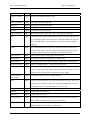
TABLE OF CONTENTS
1. INTRODUCTION.................................................................................................................................................... 5
CONVENTIONS ............................................................................................................................................................ 5
INTERFACES ................................................................................................................................................................ 5
POWER UP ................................................................................................................................................................ 10
LOGGING ON............................................................................................................................................................. 10
THE PROMPT ............................................................................................................................................................. 11
HTC-1100E CARD ADDRESSES ................................................................................................................................ 11
SPECIAL KEYS .......................................................................................................................................................... 12
The Enter Key ...................................................................................................................................................... 13
The Escape Key.................................................................................................................................................... 13
The Greater Than {>} Key................................................................................................................................... 13
The Right Bracket {]} Key ................................................................................................................................... 13
The Less Than {<} Key ........................................................................................................................................ 13
The Left Bracket {[} Key ...................................................................................................................................... 13
The Question Mark {?} Key ................................................................................................................................. 14
The {A} or {a} Key ............................................................................................................................................... 14
The {B} or {b} Key ............................................................................................................................................... 14
The Asterisk {*} Key ............................................................................................................................................ 14
2. MAIN MENU ......................................................................................................................................................... 14
3. PROVISIONING MENU ...................................................................................................................................... 16
THE SYSTEM CONFIGURATION SUB-MENU ................................................................................................................ 17
List Plug-Ins......................................................................................................................................................... 18
List power Supply Attributes ................................................................................................................................ 20
Modify Power Supply Attributes .......................................................................................................................... 20
List Pulse Metering Frequency ............................................................................................................................ 20
List Timing Source ............................................................................................................................................... 20
Modify Timing Source Priority ............................................................................................................................ 21
THE CROSS-CONNECT SUB-MENU............................................................................................................................. 22
List Cross-Connects ............................................................................................................................................. 23
Modify Plug-In Cross-Connects........................................................................................................................... 23
Delete Plug-In Cross-Connects ........................................................................................................................... 25
Modify Groomed Cross-Connects........................................................................................................................ 26
Delete Groomed Cross-Connects......................................................................................................................... 27
THE TRANSCEIVER SETTING SUB-MENU ................................................................................................................... 28
List Transceiver Settings...................................................................................................................................... 28
Modify Transceiver Settings................................................................................................................................. 30
List BER Thresholds ............................................................................................................................................ 33
Modify BER Thresholds ....................................................................................................................................... 34
THE DCS PROVISIONING SUB-MENU ........................................................................................................................ 37
List Channel Attributes ........................................................................................................................................ 38
Modify Channel Attributes ................................................................................................................................... 38
THE SPECIAL CIRCUITS SETTINGS SUB-MENU ........................................................................................................... 39
List Analog Circuit Settings ................................................................................................................................. 40
Modify Analog Circuit Settings............................................................................................................................ 41
List Digital Circuit Settings ................................................................................................................................. 50
Modify Digital Circuit Settings ............................................................................................................................ 50
F/N: C10-41021001 Rev:1F
2
HTC-1100E Craft Interface
Hitron Technology Inc.
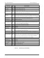
4. MAINTENANCE MENU...................................................................................................................................... 68
LIST CURRENT ALARMS............................................................................................................................................ 68
LIST ALARM HISTORY .............................................................................................................................................. 70
LIST USE PORT.......................................................................................................................................................... 70
LIST PERFORMANCE DATA ....................................................................................................................................... 71
OPERATE LOOP ......................................................................................................................................................... 75
OPERATE ALARM CUT-OFF ...................................................................................................................................... 76
CLEAR ALARM HISTORY........................................................................................................................................... 77
OPERATE SWITCHING................................................................................................................................................ 78
5. TESTING MENU................................................................................................................................................... 82
PERFORM LAMP TEST ............................................................................................................................................... 82
PERFORM ALARM TEST............................................................................................................................................. 83
Drop Test Sub-menu ............................................................................................................................................ 88
PERFORM DROP TEST ............................................................................................................................................... 88
LIST DROP TEST THRESHOLDS .................................................................................................................................. 90
LIST TERMINAL TEMPERATURES............................................................................................................................... 91
6. TRAFFIC MENU................................................................................................................................................... 92
LIST CURRENT TRAFFIC STATUS ............................................................................................................................... 93
LIST TRAFFIC STATISTICS ......................................................................................................................................... 93
RESET TRAFFIC MONITORING REGISTERS ................................................................................................................. 94
SET TRAFFIC ALARM THRESHOLD ............................................................................................................................ 95
7. ADMINISTRATION MENU ................................................................................................................................ 96
THE DATE AND TIME SUB-MENU .............................................................................................................................. 97
List Date and Time............................................................................................................................................... 98
Set Date................................................................................................................................................................ 98
Set Time................................................................................................................................................................ 99
THE SECURITY SUB-MENU ........................................................................................................................................ 99
List User Security Data...................................................................................................................................... 100
Set User Security Data....................................................................................................................................... 100
Delete User Security Data ................................................................................................................................. 103
THE TERMINAL OPTIONS SUB-MENU ...................................................................................................................... 104
List Terminal Options ........................................................................................................................................ 104
Set Terminal Options ......................................................................................................................................... 105
List Terminal ID................................................................................................................................................. 107
Set Terminal ID.................................................................................................................................................. 107
8. THE V5 CONFIGURATION SUB-MENU ....................................................................................................... 108
LIST V5 ID PROVISIONING ...................................................................................................................................... 108
MODIFY V5 ID PROVISIONING ................................................................................................................................ 109
DELETE V5 ID PROVISIONING ................................................................................................................................ 109
LIST C-CHANNEL PROVISIONING ............................................................................................................................ 110
MODIFY C-CHANNEL PROVISIONING ...................................................................................................................... 110
DELETE C-CHANNEL PROVISIONING ....................................................................................................................... 112
LIST E1 LINK MAP .................................................................................................................................................. 112
LIST LE-AN PORT MAP .......................................................................................................................................... 114
MODIFY LE-AN PORT MAP .................................................................................................................................... 114
DELETE LE-AN PORT MAP .................................................................................................................................... 115
F/N: C10-41021001 Rev:1F
3
HTC-1100E Craft Interface
Hitron Technology Inc.
CROSS CONNECT SUB-MENU .................................................................................................................................. 115
LIST AN CROSS-CONNECTS .................................................................................................................................... 116
DELETE AN CROSS-CONNECTS .............................................................................................................................. 116
SPECIAL CIRCUITS SETTINGS MENU ....................................................................................................................... 117
LIST V5 CIRCUIT SETTINGS .................................................................................................................................... 118
F/N: C10-41021001 Rev:1F
4
HTC-1100E Craft Interface
Hitron Technology Inc.
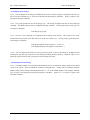
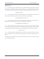
1. Introduction
1.1.
This document describes the basic HTC-1100E Craft Interface. The craft interface is a simple, menu-driven
software interface which provides facilities for provisioning, maintaining, traffic monitoring, testing and administering the HTC-1100E system.
1.2.
This manual assumes the reader possesses a general knowledge of the HTC-1100E System. If more basic
information is needed, consult the System Overview before continuing with this Craft Interface manual.
1.3.
The introduction gives a summary of the conventions used in this document. It also lists special keys and
describes the menus used to operate the system. After the introduction, separate sections for each menu discuss the
various menu commands and the input they require.
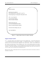
Conventions
1.4.
In this document, words or characters enclosed in brackets {} are keys on the terminal keyboard. When
the {} brackets appear, press the key for the character or word enclosed in {} brackets, but do not type the {} brackets. For example, {ENTER} means press the enter key. {>} means press the "greater than" key.
1.5.
Some keyboards use {RETURN} rather than{ENTER}. Other keyboards use a bent arrow pointing toward the alphabetic character keys. If the keyboard uses something other than {ENTER}, substitute that key when
this manual says to press {ENTER}.
1.6.
The HTC-1100E System is designed to be simple yet powerful. A LET or RST may be set up and operated without using the Craft Interface software. On power up, the system will automatically perform all necessary
initialization routines for the CPU, the PSU and any user interface cards that have been mounted in the terminal
cabinet. The software interface has been added to provide greater flexibility in operating the system.
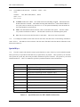
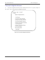
1.7.
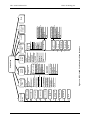
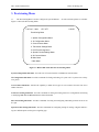
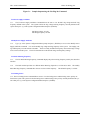
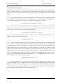
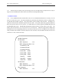
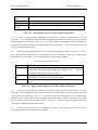
The system uses a menu-driven craft interface that requires no switches, straps or other forms of manual intervention. The software supports all the commands needed to administer, maintain and provision the system.
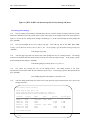
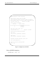
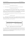
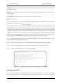
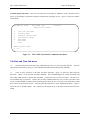
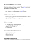
Figure 1-a shows the menu structure of the HTC-1100E Craft Interface.
Interfaces
1.8.
To use the craft interface, the operator needs a 9-pin RS232-C connector cable connected to either a simple
terminal such as a VT 100 or a computer running a terminal emulation program.
1.9.
The system operates at 9600 baud. The craft interface may also be accessed remotely using a modem.
When using modems or PCs to access the craft interface, a null modem may be necessary to complete the connection.
The craft interface port is configured with pin 2 as receive, pin 3 as transmit and pin 5 as ground.
F/N: C10-41021001 Rev:1F
5
HTC-1100E Craft Interface
Hitron Technology Inc.
1.10.
If desired, the terminal may also be connected directly to the HTC-1100E backplane. However, if a direct
connection is made to the backplane, the user may not use the DB9 connector under the air ramp on the front of the
HTC-1100E. Cable length should not exceed 50 feet. Connection points are provided on the alarm contact field of
the HTC-1100E backplane. The cable should terminate to pin C5 for receive, pin D5 for transmit and a ground
should terminate to pin D7.
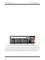
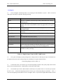
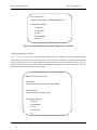
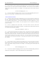
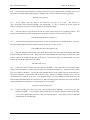
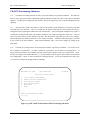
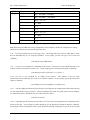
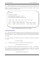
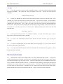
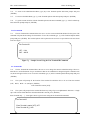
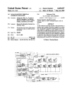
1.11
Figure 1-b shows the location of the port on the front of the LET or RST. Connect the terminal to the port
on either the LET or the RST and press {ENTER}. The system then prompts the user for User ID and Password
information.
1.12.
The HTC-1100E craft interface allows more than one user to access the system at the same time. Multiple
users may log on from remote terminals to test and monitor the system.
F/N: C10-41021001 Rev:1F
6
F/N: C10-41021001 Rev:1F
7
?
*
B
Help
Main Menu
Main Menu
All Current
? Alarm
Special Set
Menu
6
A
DCS provisioning
Transceiver Set
Cross-Connect
V5 Config.
5
4
3
2
1 System Config.
Provisioning
Menu
1
List Use Port
List Alarm
History
?
Lamp Test
4
Set Traffic Alarm
Threshold
Reset Traffic
3 Monitoring
List Traffic
2 Statistics
5
1
A All Current
3 Set Time
2 Set Date
1 List Date/Time
Date/Time
Menu
Administration
Menu
List Current Traffic
1 Status
Traffic
Menu
4
* Main Menu
? Help
B Main Menu
A All Current Alarms
List Terminal
8 Temperatures
?
Help
Main Menu
Main Menu
B
*
All Current
? Alarm
A
3
Terminal Options
Menu
Alarms
B Main Menu
List Drop Test Thre. A All Current Alarms
A All Current Alarms
* Main Menu
B Main Menu
B Main Menu
? Help
Main Menu
* Main Menu
*
? Help
Help
Security Menu
?
2
1 Perform Drop Test
5
Drop Test Menu
7
6 Alarm Test
2
Testing
Menu
3
Figure 1-a. HTC-1100E Craft Interface Menu Structure
Help
* Main Menu
B Main Menu
A All Current Alarms
9 List Plug-In status
8 Operating Switching
7 Clear Alarm History
6 Operate Alarm Cut-Off
5 Operate Loopback
4 List Performance Data
3
2
1 List Current
Alarm
Maintenance
Menu
2
Main Menu
All Current
Alarms
A
? Help
* Main Menu
1 List User Security Data
2 Set User Security Data
3 Delete User Security Data
A All Current Alarms
B Main Menu
? Help
1 List User Security Data
2 Set User Security Data
3 Delete User Security Data
A All Current Alarms
B Main Menu
* Main Menu
Log Off
6
Help
?
HTC-1100E Craft Interface
Hitron Technology Inc.
F/N: C10-41021001 Rev:1F
List Plug-ins
Delete Plug-In
Cross-Connects
8
* Main Menu
7 List E1 Link Map
8 Modify E1 Link Map
9 Delete E1 Link Map
10 List LE-AN Port Map
LE-AN Port
11 Modify
Map
B Provisioning Menu
* Main Menu
? Help
? Help
* Main Menu
B Provisioning Menu
Map
A All Current Alarms
12 Delete LE-AN Port
B Provisioning Menu
6 Delete C-Channel
8 Modify Timing
Source
A All Current Alarms
DCS
Provisioning
5
Special
Circuits
Settings
6
List Transceiver
1 Settings
A
All Current
Alarms
B Provisioning Menu
Main Menu
*
Help
?
List Analog
List Channel
1 Attributes
1 Circuit Settings
2 Modify Channel 2 Modify Analog
2 Modify
Circuit Settings
Attributes
Transceiver Settings
List
Digital
All
Current
List
BER
A Alarms
3
3
Circuit Settings
Thresholds
Provisioning
Modify Digital
B Menu
Modify BER
4 Circuit Settings
4
Threshold
List V5 Circuit
* Main Menu
All Current
5
A Alarms
Settings
Help
?
B Main Menu
Modify V5
6 Circuit Settings
* Provisioning Menu
A All Current
? Help
Alarms
Transceiver
Setting
4
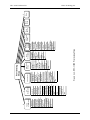
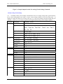
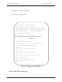
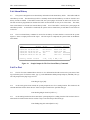
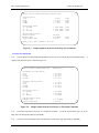
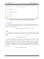
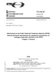
Figure 1-a-1. HTC-1100E Provisioning Menu
? Help
A All Current Alarms
7 Modify AN Cross-Connects
8 Delete AN Cross-Connects
6 List AN Cross-Connects
5 Modify C-Channel
Modify Groomed
4 Cross-Connects
5 Delete Groomed
Cross-Connects
3
7 List Timing /source
3 Delete V5 ID
2 Modify Plug-In
Cross-Connects
1 List Cross-Connects
Cross-Connect
3
4 List C-Channel
List P/M Freq.
2 Modify V5 ID
1 List V5 ID
V5
Configuration
2
6 Modify P/M Freq.
5
4 Modify P/S Attri.
3 List P/S Attri.
1
System
Configuration
1
Provisioning
Menu
Main
Menu
B
Main
Menu
*
Help
?
HTC-1100E Craft Interface
Hitron Technology Inc.
HTC-1100E Craft Interface
Hitron Technology Inc.
DB9 RS232-C Port Connector
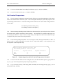
Figure 1-b HTC-1100E Channel Bank Assembly Showing Location of DB9 RS232-C Port
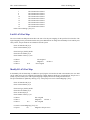
1.13.
For autonomous alarm reporting, equipment inventory and other desired reports, output may be automatically directed to a printer. Autonomous reporting requires that a printer be connected to the printer port on the terminal or computer which is interfaced to the HTC-1100E equipment. Consult the user manual for the terminal or
terminal emulation software being used for specific instructions about how to set up a printer for this purpose.
F/N: C10-41021001 Rev:1F
9
HTC-1100E Craft Interface
Hitron Technology Inc.
Power Up
1.14.
The first time when the HTC-1100E is powered up, the system performs a power up diagnostics routine.
The CPU performs an internal initialization routine for both the software and hardware components of the active
CPU card. Then the CPU performs a series of terminal diagnostics on the components of the local terminal to verify functionality of communications links, data paths and audio paths. If a standby CPU is installed, a series of diagnostic tests is run on the standby CPU to verify its hardware and software operability. All LED lamps are tested
during the power up diagnostics testing by first turning on all LEDs in the terminal. As each LED is tested, it is
turned off. The complete LED test procedure takes about one minute. A standing FAIL LED will indicate a failure
state of a card after the system turn-up diagnostics test is performed. A message is printed on the screen identifying
any cards which report failures during the terminal diagnostic procedure. Finally, the CPU performs a system test to
verify data paths and communications links throughout the system (the LET and any RST’s in the network). If no
data paths or communications links exist between the LET and an RST in the network, the system will report that the
LET cannot communicate with that RST. The LET will power up alarm free only if it is successfully communicating with all RSTs in the network.
1.15.
When the initial power up testing is completed, a report is printed on the terminal screen. The terminal is
ready for traffic when the green ACTV LED is lit on the active CPU. If a standby CPU is installed, the yellow
STBY light should be lit. Any card that failed the power up diagnostics routines will show a lighted red FAIL LED
on the card that failed.
Logging On
1.16.
To use the HTC-1100E craft interface, establish a connection. Using a 9-pin RS232-C connector cable,
connect the terminal to the LET or RST. When properly connected, the system prompt appears on the terminal
screen to ask for user name and password key-in.
1.17.
If the system is being started for the first time, no user I. D. or password information has been entered into
the system. In this case, pressing {ENTER) at each of the log-in prompts will give the user access to the
HTC-1100E Craft Interface. In case of the security has been set up, user has to input the correct user name and
password to get access to the Craft Interface. For more information on User IDs and Passwords, see the "Administration" section.
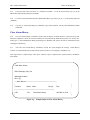
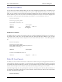
1.18.
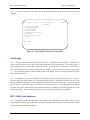
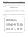
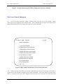
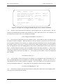
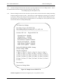
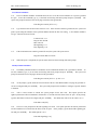
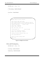
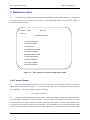
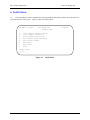
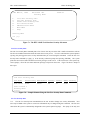
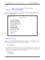
When a correct User ID and Password have been entered, the terminal displays the HTC-1100E Craft Interface Main Menu shown in Figure 1-c.
1.19.
HTC-1100E commands fall into one of five major categories: Provisioning, Maintenance, Testing, Traffic
and Administration. In addition, the Main Menu lists three other options: the Log Off option to end the craft interface session, the A option to list all current alarms, and the {?} Help option to request help with a particular command or menu. If Help is requested at a data input prompt, the system lists the valid input values for the current
prompt.
F/N: C10-41021001 Rev:1F
10
HTC-1100E Craft Interface
Hitron Technology Inc.
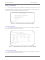
1.20.
To make a selection from the menu, type the number displayed beside the desired menu item and press
{ENTER}.
THU Mar 12, 1998
1.
2.
3.
4.
5.
6.
A.
?
HTC-1100E LET
Main Menu
14:48:45
Provisioning Menu
Maintenance Menu
Testing Menu
Traffic Menu
Administration Menu
Log Off
All Current Alarms
Help
Main Menu
> [1]:
Figure 1-c
HTC-1100E Craft Interface Main Menu
The Prompt
1.21.
The HTC-1100E craft interface uses the Greater Than {>} symbol as the system prompt. It marks the position on the screen where the user types menu selection numbers or other needed input. One Greater Than {>}
symbol indicate the top level of the HTC-1100E menu system. As the user moves to lower levels of the menu tree,
the system adds Greater Than symbols to the prompt. For example, at the second menu level, the prompt becomes
{>>}. By counting the number of Greater Than symbols in the prompt, the user can easily determine his current
level in the menu structure.
1.22.
In addition, the system also displays the default input value for the prompt where the user is working.
This value appears enclosed in brackets [ ] following the prompt symbol. If the displayed value is the correct one,
pressing {ENTER} at the prompt accepts the displayed default value as the current input value. Otherwise, the user
has two options. If the desired value is not known, press either bracket key ([ or ]) to begin scrolling through the
acceptable entry values until the desired value is displayed, then press {ENTER} to accept the displayed value as the
input for the prompt. If the desired value is known, just type it after the prompt and press {ENTER}.
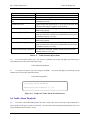
HTC-1100E Card Addresses
1.23.
Many HTC-1100E commands require a Card Address. The Card Address is the unique location of a particular interface card in the HTC-1100E system. It identifies the physical location of the card in terms of the terminal,
terminal shelf number and shelf slot number.
F/N: C10-41021001 Rev:1F
11
HTC-1100E Craft Interface
1.24.
Hitron Technology Inc.
Card Addresses take the form: <terminal> - <shelf> - <slot>
where:
terminal =
LET, RST1, RST2, RST3, ..., RSTn
shelf = 1 to 8
slot = 1 to 26
z
Terminal - Either LET or RST. LET stands for the Local Exchange Terminal. RST stands for the
Remote Subscriber Terminal. The number following RST indicates the nth RST terminal address in
the system, where n could be any value from 1 to 15.. The system automatically stores this number in
the system database at system turn-up.
z
Shelf - The shelf number indicates the shelf, where a card resides in the system. The LET or RST
may contain a maximum of 8 shelves. The first shelf is shelf one, also called the primary shelf.
z
Slot - The slot refers to the shelf slot where a card resides. There are 26 slots in each shelf.
1.25.
For example, the address for the card in the first slot on the first shelf of the Local Exchange Terminal becomes: LET-1-1. The address for the card in the sixth slot on the fifth shelf of the first Remote Subscriber Terminal becomes: RST1-5-6
Special Keys
1.26.
The HTC-1100E Craft Interface assigns special functions to some of the keys on the terminal keyboard.
These special keys are provided to make data entry as quick and easy as possible. These special keys are not needed to operate the system, they have been provided to facilitate the process if desired. The special keys are listed
and discussed below. Table 1-A summarizes special keys and their functions in the Craft Interface.
Special Key
Function in HTC-1100E Craft Interface
>
Toggle forward through current valid data values
﹞
<
Toggle forward through current valid data values
﹝
?
Toggle backward through current valid data values
Help
*
Return to Main Menu
A or a
List all current alarms
B or b
Back up to the previous menu
ENTER
Execute the selected command
ESC
Back up to previous menu or escape from current command
Toggle backward through current valid data values
Table 1-A.
F/N: C10-41021001 Rev:1F
Special Characters for HTC-1100E Craft Interface
12
HTC-1100E Craft Interface
Hitron Technology Inc.
The Enter Key
1.27.
The {ENTER} key is usually the largest key on the keyboard. It is located to the right of the alphabetic
characters. On some keyboards, the key says {RETURN}; on others it is marked with a bent arrow. Pressing the
{ENTER} key executes HTC-1100E commands.
The Escape Key
1.28.
The location of the {ESC} key varies from one keyboard to another. It usually is found in the upper left
hand corner of the keyboard. If pressed before the final {ENTER} on a command line, the {ESC} key allows the
user to escape from a command before execution. When pressed at a menu, it allows the user to back up to the previous menu.
The Greater Than {>} Key
1.29.
The Greater Than key adds one to the value displayed in the input field. If no data appears in the input
field, the Greater Than key provides the lowest value allowed for that field. Press the Greater Than key as many
times as needed to reach the desired value. If the correct value is known, you may enter it. Data entry does not
require the use of the Greater Than key.
The Right Bracket {]} Key
1.30.
The {]} key works just like the Greater Than Key. Pressing the {]} key adds one to the current value in
the data field. If no value appears in a data field, it provides the lowest value allowed in that field. If the correct
value is known, data can be entered without using this key.
The Less Than {<} Key
1.31.
Pressing the Less Than key subtracts one from the data displayed on the screen. If there is no value on the
screen, pressing the Less Than key provides the highest value allowed for this data field. This key may be pressed
several times until the screen displays the desired value. If the correct value is known, enter it without using the
Less Than key.
The Left Bracket {[} Key
1.32.
The Left Bracket key works just like the Less Than Key. It subtracts one from the current value in the
data field. If no value is displayed, it provides the highest value allowed for this field. This key is not required.
If the correct value is know, you may enter it.
F/N: C10-41021001 Rev:1F
13
HTC-1100E Craft Interface
Hitron Technology Inc.
The Question Mark {?} Key
1.33.
This {?} key provides help with HTC-1100E commands and menus. Pressing the {?} key provides the
user with a list of the input options available for the prompt where the user is currently working. Pressing the {?}
key at a menu level prompt causes the current working menu to be displayed on the screen.
The {A} or {a} Key
1.34.
The {A} key allows the system operator to get a listing of all current alarms from any prompt in the
HTC-1100E Craft Interface. To obtain the list of current alarms, press the {A} or {a} key at any system prompt
and press {ENTER}. The system will print a list of all current alarms on the screen and return to the last menu being used.
The {B} or {b} Key
1.35.
The {B} key allows the user to backup to the previous menu. This option usually appears on the menu
screen. The system will accept either the upper case or the lower case B.
The Asterisk {*} Key
1.36. From anywhere in the HTC-1100E Craft Interface, pressing the key returns to the Main Menu.
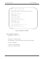
2. Main Menu
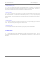
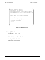
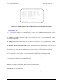
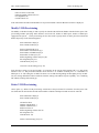
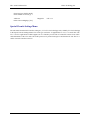
2.1.
The Main Menu lists the major command groups for the HTC-1100E Craft Interface software. There are
no executable commands available at this level. The command groups are described below. Figure 2-a shows the
Main Menu.
F/N: C10-41021001 Rev:1F
14
HTC-1100E Craft Interface
Hitron Technology Inc.
THU MAR 12, 1998
1.
2.
3.
4.
5.
6.
A.
?
HTC-1100E LET
Main Menu
14:48:45
Provisioning Menu
Maintenance Menu
Testing Menu
Traffic Menu
Administration Menu
Log Off
All Current Alarms
Help
Main Menu
> [1]:
Figure 2-a. HTC-1100E Craft Interface Main Menu
Provisioning - Provides commands for configuring the system. Command options include configuration commands for groomed circuits and POTS (Plain Old Telephone Service). Transceiver configurations are also done
using the Provisioning Menu.
Maintenance - Performs system maintenance functions such as listing current alarms and alarm history, listing performance information about transmission spans and operating the alarm cut off.
Testing - Performs system testing functions. Options include running lamp and alarm testing as well as subscriber
line drop testing. Temperatures in remote cabinets may also be monitored with commands in the Testing Menu.
Traffic - Lists traffic statistics and allows resetting of traffic statistics information. This menu also provides the
ability to set thresholds for traffic alarms.
Administration - Provides system date, time and screen display control functions, provides commands to add,
change or remove users and user passwords in the system.
Log-Off - Ends the current user’s session in the HTC-1100E Craft Interface.
A - List All Current Alarms occurring in the system.
? - Provides help with the menu screen or command currently displayed.
To make a choice from the Main Menu, type the number beside that choice at the system prompt and press
{ENTER}
F/N: C10-41021001 Rev:1F
15
HTC-1100E Craft Interface
Hitron Technology Inc.
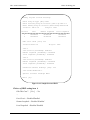
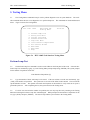
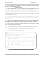
3. Provisioning Menu
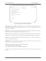
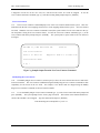
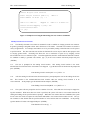
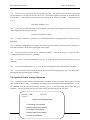
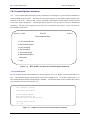
3.1.
The Provisioning Menu is used to configure the system hardware. Several sub-menu options are available.
Figure 3-a shows the Provisioning Menu.
Tue Dec 7, 1999
HTC LET
11:56:55
Provisioning Menu
1. System Configuration Menu
2. V5 Configuration Menu
3. Cross-Connect Menu
4. Transceiver Settings Menu
5. DCS Provisioning Menu
6. Special Circuits Settings Menu
A. All Current Alarms
B. Main Menu
*. Main Menu
Figure 3-a. HTC-1100E Craft Interface Provisioning Menu
System Configuration Sub-menu - Provides a list of current interface card addresses and card status.
V5 Configuration Sub-menu –Provides commands for listing and setting V5 system. All V5 system refer to chapter 8, please.
Cross-Connect Sub-menu - Provides the capability to build various types of cross-connects from one time slot to
another time-slot.
Transceiver Setting Sub-menu - Provides commands for listing and setting transceiver configurations and listing
or modifying BER Red and BER Maintenance alarm thresholds.
DCS Provisioning Sub-menu - Provides commands for listing and configuring individual groomed circuits on an
E1 span.
Special Circuits Settings Sub-menu - Provides commands for configuring settings for analog or digital cards having user defined options such as gain or signaling type.
F/N: C10-41021001 Rev:1F
16
HTC-1100E Craft Interface
Hitron Technology Inc.
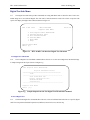
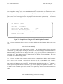
The System Configuration Sub-menu
3.2
The System Configuration Sub-menu provides commands that allow the user to properly configure the
HTC-1100E. Figure 3-b shows the System Configuration Sub-menu.
Tue Dec 7, 1999
HTC LET
11:56:55
System Configuration Menu
1. List Plug-Ins
3. List Power Supply Attributes
4. Modify Power Supply Attributes
5. List Pulse Metering Frequency
6. Modify Pulse Metering Frequency
7. List Timing Source
8. Modify Timing Source Priority
A. All Current Alarms
B. Provisioning Menu
* Main Menu
Figure 3-b. The System Configuration Sub-menu
F/N: C10-41021001 Rev:1F
17
HTC-1100E Craft Interface
Hitron Technology Inc.
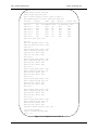
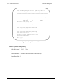
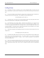
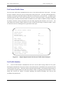
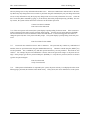
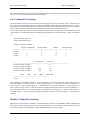
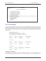
List Plug-Ins
3.3
The List Plug-Ins command provides a list of all plug-in cards installed in a system. Table 3-A lists the
status types which may be reported in the plug-ins listing.
Plug-In Status
Failed
Definition
Unit type is established, but the plug-in that is seated in the slot is not operating properly
Unit type is established. The plug-in is seated in the slot and is operating
properly. This doesn’t mean that the card is carrying traffic or serving subscribers.
The unit type was established but the defined plug-in that was once seated
is no longer found.
The card slot has no plug-in type established and has no plug-in card seated
in the slot.
The established card type does not match the plug-in actually seated in the
slot.
The card in this slot is not in service.
The card has been disabled via Craft Interface commands.
The unit is established and is a standby for the active unit.
The unit is established and is currently in use.
In-Service
Missing
Unequipped
Wrong Type
Out of service
Disabled
Standby
Active
Notes:
Established:
System software has assigned a particular plug-in type to a given card slot.
This is accomplished by seating a card into an unequipped slot.
A plug-in card has been physically inserted into the card slot in the Channel Bank Assembly card cage.
Seated:
Table 3-A. Plug-In Status Values for HTC-1100E System
3.4.
The system will display a prompt asking for the starting location for this Plug-Ins report. The default location appears in brackets in the system prompt. Press {ENTER} to accept the default selection.
Enter Starting Plug-In Location: [LET-1-1]
3.5.
If the default value is not desired, type the desired beginning location at the system prompt. The location
takes the form terminal-shelf-slot. A dash separates each of the location fields.
3.6.
The terminal may be LET or RST1 to RSTxx. Shelf may be any number from 1 to 8. Slot may be any number from 1 to 26. If the desired beginning location is known, type it at the prompt and press {ENTER}. LET- 1-1
is the lowest beginning location; RSTxx-8-26 is the highest where xx represents the highest RST number stored in
F/N: C10-41021001 Rev:1F
18
HTC-1100E Craft Interface
Hitron Technology Inc.
in the system database. If an incorrect value is entered into the data field, the system displays an error message
identifying the problem and listing a range of acceptable values.
3.7.
When all three components of the beginning location have been entered, the system prompts the user for the
ending location.
Enter Ending Plug-In Location: [RST1-1-26]
3.8.
The ending location address follows the same rules as those for the beginning location.
3.9.
The ending location must be equal to or greater than the beginning location. For example, if RST1-1-1
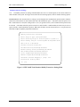
were entered as the beginning location, the ending location must be RST1-1-1 or higher. LET-1-1 would be less
than RST1-1-1 and could not be entered as the ending location.
3.10.
When correct beginning and ending locations have been entered, the HTC-1100E system will print a report
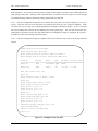
on the screen. Table 3-A shows a listing of the different status values that may appear on this report. Figure 3-c
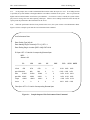
shows a sample printout from this report. After the report is completed, the System returns to the System Configuration Sub-menu.
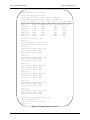
List Plug-Ins
Enter Plug-In Type [All]: All
Enter Starting Plug-In Location [LET-1-1]: LET-1-1
Enter Ending Plug-In Location [RST1-8-26]: RST1-8-26
Location
Plug-In
Status
Version
Assembly
Serial Number
------------------------------------------------------------------------------LET-1-6
DD64
In Service
LET-1-13
E1X-XCVR Out Of Service1B 2.0.10
LET-1-17
FO-XCVR
Standby
LET-1-22
FO-XCVR
Active
3D 3.0.5
2004-0100
LET-1-23
CPU
Standby
1D 5.0.9
2008901001 8010000003
LET-1-24
CPU
Active
LET-1-25
L-PSU
In Service
1B
0101-0002
8000200024
RST1-1-8
RI-POTS
In Service
3E 2.2.6
2003-0100
7014903470
RST1-1-21 FO-XCVR
Standby
RST1 1 22 FO XCVR
Active
F/N: C10-41021001 Rev:1F
1B 2.1.3
3D 3.0.6
1D 5.0.9
3D 3.0.6
3D 3 0 6
19
2008301001 9018300045
2038-0100
2004-0100
9010100089
7010401261
8010400272
2008901001 8010000021
2004-0100
2004 0100
7010400320
8010400455
HTC-1100E Craft Interface
Figure 3-c.
Hitron Technology Inc.
Sample Output using the List Plug-Ins Command
List Power Supply Attributes
3.11.
The List Power Supply Attributes Command allows the user to view the PSU ring voltage and PSU ring
frequency defined in the system. The system will list the ring voltage and ring frequency currently defined in the
system when press {3} at the System Configuration Menu and press {ENTER}.
PSU Ring Voltage: 85 volts
PSU Ring Frequency: 20.0Hz
Modify Power Supply Attributes
3.12.
Type {4} at the System Configuration Menu prompt and press {ENTER} to access to the Modify Power
Supply Attributes command. It is used to modify ring voltage and ring frequency in the system. The ringing voltage and frequency are both software selectable. There are totally 20 different frequency values and 4 ringer voltage
levels can be selected by user. The 85 Volt and 20 Hz are the default voltage and frequency settings.
List Pulse Metering Frequency
3.13.
The List Pulse Metering Frequency Command displays the pulse metering frequency used by the subscriber
interface.
3.14
The RST terminal provides two different Pulse Metering frequencies: 12 kHz and 16 kKz. The modify
Pulse Metering Frequency command allow the user to select wither frequency. The default frequency is 16 kHz.
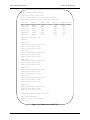
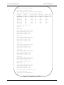
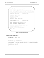
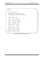
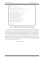
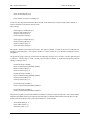
List Timing Source
3.15 The List Timing Source Command allows users to view the timing source and the timing source priority defined in the system. The system will list the timing source and the timing source priority currently defined in the system when press {7} at the System Configuration Menu and press {ENTER}.
F/N: C10-41021001 Rev:1F
20
HTC-1100E Craft Interface
Hitron Technology Inc.
List Timing Source
Current Timing Source: (1) Data Module Slot 10
Timing Source Priority:
1. External
2. Clock Card
3. Loop
4. Data Module
5. Internal
Figure 3-d Sample Output using the List Timing Source Command
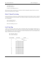
Modify Timing Source Priority
3.16.
Type {7} at the System Configuration Menu prompt and press {ENTER} to access to the Modify Timing
Source Priority command. It is used to modify timing source priority in the system. The system defined External and
Internal Timing Sources have the highest and lowest priority separately, It can’t be changed. The other of priority
timing sources can be selected by user. No matter user changed the Timing Source Priority at LET side or RST side,
only LET side Timing Source Priority can be changed.
Modify Timing Source Priority
First Priority:
Timing Source Type [Clock Card]: Data Module
Second Priority:
Timing Source Type [Loop]: Loop
Timing Source Priority:
1. External
2. Data Module
3. Loop
4. Clock Card
5 I t
F/N: C10-41021001 Rev:1F
l
21
HTC-1100E Craft Interface
Hitron Technology Inc.
Figure3 –e Sample Output using the Modify Timing Source Priority Command
The Cross-Connect Sub-menu
3.17.
The Cross-Connect Sub-menu contains commands which allow the user to list, modify or delete
cross-connects between different slots in channel banks. These commands may be used to cross-connect circuits
from one POTS card to another. Next figure shows the Cross-Connects Sub-menu.
Tue Dec 7, 1999
HTC LET
11:57:16
Cross-Connect Menu
1. List Cross-Connects
2. Modify Plug-In Cross-Connects
3. Delete Plug-In Cross-Connects
4. Modify Groomed Cross-Connects
5. Delete Groomed Cross-Connects
6. List AN Cross-Connects
7. Modify AN Cross-Connects
8. Delete AN Cross-Connects
A. All Current Alarms
B. Provisioning Menu
* M i M
Figure 3-f. HTC-1100E Craft Interface Cross-Connect Sub-menu
3.18.
When slot to slot cross-connects are used, the system builds cross-connects for all circuits on the cards occupying the two slots specified in the Plug-In Cross-Connects commands. These cross-connects are done sequentially (i.e., circuit one on the "From" card is mapped to circuit one on the "To" card; circuit two on the "From" card
F/N: C10-41021001 Rev:1F
22
HTC-1100E Craft Interface
Hitron Technology Inc.
is mapped to circuit two on the "To" card, etc.) until all circuits on the two cards are mapped. To use the
Cross-Connect Sub-menu commands, type {3} at the Provisioning Menu prompt and press {ENTER}.
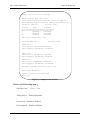
List Cross-Connects
3.19.
The List Cross-Connects command displays a list of the cross-connects defined in the system. This command lists both the slot to slot mappings and circuit to circuit mappings defined in the system. All cross-connects
are listed. When the List Cross-Connects command is issued, the system searches for all cross-connects in the system and prints a listing of all cross-connects found. To issue the List Cross-Connects command, type {1} at the
Cross-Connects Sub-menu prompt and press {ENTER}. The system prints a report similar to the one shown in
next figure.
THU MAR 12, 1998 HTC-1100E LET
14:48:45
List Cross-Connects
LET-1-1 to LET-1-22
Mapped to RST1-1-1 to RST1-1-22
Cross-Connects Menu
» [1] :
Figure 3-g Sample Output From the List Cross-Connects Command
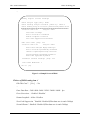
Modify Plug-In Cross-Connects
3.20.
The Modify Plug-In Cross-Connects is used to specify a slot to slot cross-connect between two cards in different slot locations. The cross-connects established using the Modify Plug-In Cross-Connects command are done
sequentially for all circuits on the two cards. For example, if two POTS cards are mapped using the Modify
Plug-In Cross-Connects Command, circuit one on the first POTS
3.21.
To use the Modify Plug-In Cross-Connect command, type {2} at the Cross-Connect Sub-menu prompt and
press {ENTER}. The system prompts for the “From” plug-in location. This location is the terminal-shelf-slot location of the card that is to be mapped. Type the card location and press {ENTER}
Enter From Plug-In Location[LET-1-1]: LET-1-1
F/N: C10-41021001 Rev:1F
23
HTC-1100E Craft Interface
Modify
Hitron Technology Inc.
Plug-In
Cross
Enter From Plug-In Location [LET-1-1]
:LET-1-1
Enter To Plug-In Location
[RST-8-26]
Enter Number of Slots [1] : 2
:RST1-1-1
Overwrite Current Mapping ? [Yes]: Yes
LET-1-2
Mapped to
RST1-1-2
Cross-Connects Menu
>>> [3]:
Figure 3-h. Sample Screen Using the Modify Plug-In Cross-Connects Command
3.22.
After the “From” location has been entered, the system prompts for the “To” plug-in location. The “To”
location is the terminal-shelf-slot location of the card where the “From” card circuits are to be cross-connected. At
the prompt, type the location of the “To” card and press {ENTER}.
Enter To Plug-In Location[RST1-8-26]: RST1-1-1
3.23.
The system now prompts the user to enter a number of slots. If more than one card is to be mapped, enter
the number of cards to be mapped. When more than one card is specified, the system moves from one slot to the
next in sequence at both the “From” and the “To” locations until the specified number of slots have been mapped.
For example, using the “From” and “To” locations specified in the sample prompts and using two as the number of
slots to be mapped, the results of the Modify Plug-In Cross-Connects would be that all circuits on the card in slot
LET-1-1 would be mapped in sequence to the corresponding circuits on the card in slot RST1-1-1. After the first
card slots are mapped, the system would move to slot LET-1-2 and map all circuits on the card in that slot to their
corresponding circuits on the card in slot RST1-1-2. At the prompt, type the number of slots to be mapped and
press {ENTER}.
Enter Number of Slots [1]: 2
3.24.
After the number of slots is specified, the system checks to see if mappings for those slots already exist. If
the system finds mappings, the user is prompted to overwrite the existing mappings. If the user says "Yes", the existing mappings will be overwritten with the new mappings. If the user responds "No", the System does not overwrite the old mappings with the new. At the prompt, type the appropriate response and press {ENTER}.
Overwrite Current Mapping[Yes]: Yes
3.25.
After the user responds to the overwrite prompt, the system prints a listing of the current mappings and returns to the Cross-Connect Sub-menu prompt.
F/N: C10-41021001 Rev:1F
24
HTC-1100E Craft Interface
Hitron Technology Inc.
Delete Plug-In Cross-Connects
3.26.
The Delete Plug-In Cross-Connects allows the user to remove a slot to slot cross-connect between two
cards in different slot locations. The cross-connects removed using the Delete Plug-In Cross-Connects command
are done sequentially for all circuits on the two cards. Figure 3-g shows a typical Delete Plug-In Cross-Connects
screen.
3.27.
To use the Delete Plug-In Cross-Connects command, type {3} at the Cross-Connect Sub-menu prompt and
press {ENTER}. The system prompts for the "From" plug-in location. This location is the terminal-shelf-slot location of the card whose mapping is to be deleted. Type the card location and press {ENTER}.
Enter From Plug-In Location[LET-1-1]: LET-1-1
3.28.
After the "From" location has been entered, the system prompts for the "To" plug-in location. The "To"
location is the terminal shelf-slot location of the card where the "From“ card circuits are currently cross-connected.
At the prompt, type the location of the "To" card and press {ENTER}.
Enter To Plug-In Location[RST1-8-26]: RST1-1-1
3.29.
The system now prompts the user to enter a number of slots. If more than one "From" card is to be
mapped, enter the number of cards to be mapped.
Enter Number of Slots [1]: 2
3.30.
When more than one card is specified, the system moves from one slot to the next in sequence at both the
"From" and the "To" locations established using the Modify Cross-Connects command until the mappings between
the specified number of slots have been deleted. For example, using the "From" and "To" locations specified in the
sample prompts and using two as the number of slots whose mappings are to be deleted, the results of the Delete
Plug-In Cross-Connects would be that the mappings between all circuits on the card in slot LET-1-1 to the corresponding circuits on the card in slot RST1-1-1 would be deleted in sequence. After the mappings on the first card
slots are removed, the system would move to slot LET- 1-2 and delete the mappings for all circuits on the card in
that slot to their corresponding circuits on the card in slot RST 1-1-2. At the prompt, type the number of slots to
whose mappings are to be removed and press {ENTER}.
Delete Current Mapping [Yes]: Yes
3.31.
After the number of slots is specified, the system checks to see if mappings for those slots exist. If the
system finds mappings, the user is prompted to delete the existing mappings. If the user says "Yes", the existing
mappings will be deleted. If the user responds "No", the system does not remove the old mappings. At the prompt,
type the appropriate response and press {ENTER}. After the user responds to the delete prompt, the system prints
a listing of the current mappings and returns to the Sub-menu prompt.
F/N: C10-41021001 Rev:1F
25
HTC-1100E Craft Interface
Hitron Technology Inc.
Delete Plug-In Cross Connects
Enter Plug-In Location [LET-1-1]
Enter Number of Slots [1] : 2
:LET-1-1
LET-1-1 to LET-1-2
RST1-1-1 to RST1-1-2
Mapped to
Delete Current Mapping ? [Yes]: Yes
Cross-Connects Menu
>>> [4]:
Figure 3-i. Sample Screen Using the Delete Plug-In Cross-Connects Command
Modify Groomed Cross-Connects
3.32.
The Modify Groomed Cross-Connects command is used to establish or change groomed cross-connects.
In general, grooming is designed to allow more efficient use of E1 trunks. Groomed cross-connects are used in a
variety of applications. For example, fractional E1 service is provided by routing certain time slots on a E1 span to
a specific location. The other time slots not used for the fractional E1 service may be used for other purposes such
as carrying general traffic. Grooming also allows the user to maximize E1 span use by assigning various
non-switched services to a common E1 span. In such an application, the HTC-1100E functions much like a DACS.
To establish or modify a groomed cross-connect, type {4} at the Cross-Connect Sub-menu prompt and press
{ENTER}.
3.33.
The user is prompted for the starting circuit location. This starting circuit location is the terminal-shelf-slot-circuit location of the circuit that is to be mapped. Type the desired circuit location at the prompt and
press {ENTER}.
Enter Starting Circuit Location [LET-1-1-1]: LET-1-1-1
3.34.
After the starting circuit location has been entered, the system prompts the user for the ending circuit location. This location is the terminal-shelf-slot-circuit location where the starting circuit location is to be
cross-connected. At the prompt, type the desired location and press {ENTER}.
Enter Ending Circuit Location[RST1-1-1-1]: RST1-1-1-1
3.35.
The system will now prompt the user for a number of circuits. More than one circuit may be mapped using this command. When more than one circuit is specified, the system will create a cross-connect between the
starting and ending circuits specified at those prompts. When that cross-connect has been established, the system
moves to the next circuit in sequence at each location and builds a cross-connect between those circuits. The system continues in this fashion until the specified number of cross-connects has been established. At the prompt,
type the number of circuits to be mapped and press {ENTER}.
Enter Number of Circuits [1]: 2
F/N: C10-41021001 Rev:1F
26
HTC-1100E Craft Interface
Hitron Technology Inc.
3.36. After the number of circuits is entered, the system prompts the user to overwrite the existing cross-connects.
If the user answers "Yes," the new circuit cross-connects are established. If the user answers "No," the command is
stopped and the existing cross-connects are not changed. At the prompt, type the desired response and press
{ENTER}.
Overwrite Current Mapping [Yes]?
Yes
3.37.
The system completes the mappings specified or escapes from the command, depending upon the user's response to the overwrite prompt. The system then returns to the Cross-Connect Sub-menu.
Delete Groomed Cross-Connects
3.38.
The Delete Groomed Cross-Connects command allows the user to remove groomed cross-connects from
the system. When the groomed cross-connect is removed, mapping for the affected circuits reverts to the system
slot to slot mapping currently specified. To use the Delete Groomed Cross-Connects command, type {5} at the
Cross-Connect Sub-menu and press {ENTER}. The system prompts the user for information to identify the
groomed to be deleted.
3.39.
The user is prompted for the circuit location. This circuit location is the LET or RST terminal-shelf-slot-circuit location of the circuit that is to be deleted. Type either the LET or RST location of the circuit
to be deleted at the prompt and press {ENTER}.
Enter Circuit Location[LET-1-1-1]:LET-1-1-1
3.40.
The system will now prompt the user for a number of circuits. More than one circuit may be deleted using
this command. When more than one circuit is specified, the system will delete the cross-connect beginning at the
starting circuit specified at the prompt. When that cross-connect has been deleted, the system moves to the next
circuit in sequence and deletes the cross-connect for that circuit. The system continues in this fashion until the
specified number of cross-connects has been deleted. At the prompt, type the number of circuits to be deleted and
press {ENTER}.
Enter Number of Circuits [1]: 2
3.41. After the number of circuits is entered, the system prompts the user to overwrite the existing cross-connects.
If the user answers "Yes," the specified circuit cross-connects will be deleted. If the user answers "No," the command is stopped and the existing cross-connects are not changed. At the prompt, type the desired response and
press {ENTER}.
Delete Current Mapping [Yes]?
Yes
3.42.
The system now completes the mappings specified or escapes from the command depending upon the user's
response to the overwrite prompt. The user is then returned to the Cross-Connect Sub-menu.
F/N: C10-41021001 Rev:1F
27
HTC-1100E Craft Interface
Hitron Technology Inc.
The Transceiver Setting Sub-menu
3.43.
The Transceiver Setting Sub-menu provides commands for listing and modifying transceiver settings and
alarm thresholds for the transceiver cards mounted in the system. Fiber optic transceivers have no user definable
settings and do not appear in any of the menus used for listing or modifying transceiver settings. The user may list
or set BER-Red and BER-Maintenance alarms for fiber optic transceivers. Next figure 3-h shows the Transceiver
Setting Menu.
Tue Dec 7, 1999
HTC LET
11:57:20
Transceiver Settings Menu
1. List Transceiver Settings
2. Modify Transceiver Settings
3. List BER Thresholds
4. Modify BER Thresholds
5. List Performance Thresholds
6. Modify Performance Thresholds
A. All Current Alarms
B Provisioning Menu
Figure 3-j. HTC-1100E Craft Interface Transceiver Settings Sub-menu
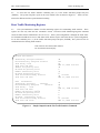
List Transceiver Settings
3.44.
The List Transceiver Settings command allows the user to list the various transceiver settings that may be
modified for a particular transceiver type. To list these settings, type {1} at the Transceiver Settings Menu prompt
and press {ENTER}. The system prompts for the plug-in type of the transceiver card whose settings are to be
listed.
Enter Plug-In Type [All]:
3.45.
At the prompt, type the name of the transceiver card type to be listed. The choices are "All" and "E1
-XCVR","E1X-XCVR", "FO-XCVR","HD-XCVR". If "All" is selected, the system reports the transceiver settings
for all transceiver types with user definable settings.
3.46.
After the transceiver type has been entered, the system prompts the user for a beginning location. This
location is the terminal-shelf-slot location where the user wishes to begin a search for transceiver cards.
Enter Starting Plug-In Location [LET-1-1]:
F/N: C10-41021001 Rev:1F
28
HTC-1100E Craft Interface
Hitron Technology Inc.
3.47.
After the starting location has been entered, the system prompts the user for an ending location. This is
the terminal-shelf-slot location where the search for transceiver cards is to stop.
Enter Ending Plug-In Location [RST1-8-26]:
3.48.
When the ending location has been entered, the system searches all slots between the starting and ending
locations looking for transceiver cards. When transceiver cards matching the specified type are found, the
system prints a listing of the settings for that card on the screen. When all card slots falling in the specified range have been searched and any matching transceiver card settings have been reported, the system
returns to the Transceiver Settings Menu prompt.
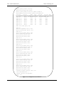
List Transceiver Settings
Enter Plug-In Type [All]: HD-XCVR
Enter Starting Plug-In Location [LET-1-1]: LET-1-10
-----------------------------------------------------------------------------Location: LET-1-10 Plug-In: HD-XCVR
Groomed Service: Enabled
Timing Source:
Disabled
PCM30 Or PCM31: PCM30
FPGA Remote Loopback: Disabled
FPGA Local Loopback: Disabled
xDSL Remote Loopback: Disabled
xDSL Local Loopback: Disabled
Far End FE1-HDSL(E1-HDSL) Setting:
E1 Line Coding: HDB3
Timeslot Assignment:
1 : Port 1, 2 : Port 2, 3 : Port 3, 4 : Port 3, 5 : Port 3, 6 : Port 3,
7 : Port 3, 8 : Port 3, 9 : Port 3, 10: Port 3, 11: Port 3, 12: Port 3,
13: Port 3, 14: Port 3, 15: Port 3, 16: Port 3, 17: Port 3, 18: Port 3,
19: Port 3, 20: Port 3, 21: Port 3, 22: Port 3, 23: Port 3, 24: Port 3,
25: Port 3, 26: Port 3, 27: Port 3, 28: Port 3, 29: Port 3, 30: Port 3,
31: Port 3,
Press Any Key
Transceiver Settings Menu
Figure 3-k. Sample Screen of HD-XCVR
Timeslot assignment: All Timeslot are mapped to port 3 except timeslot 1 and 2.
F/N: C10-41021001 Rev:1F
29
HTC-1100E Craft Interface
Hitron Technology Inc.
Modify Transceiver Settings
3.49.
The Modify Transceiver Settings command allows the user to set certain options on the various transceiver
cards available in the system. Next figure shows the E1X-XCVR setting options, E1X-XCVR has following options:
Groomed Service: The Groomed Service setting is used to designate the communication protocol used in transmissions between this transceiver card and the other end of the transmission span. If the other end of the span is not a
HTC-1100E transceiver card, this setting must be "Yes" (for groomed service), and a channel format protocol must
be selected. If the other end of the span is a transceiver card of an HTC-1100E terminal, the choice may be "No" to
specify the HTC-1100E transmission protocol. When E1X-XCVR is used in Groomed Service, it can provide local
and remote loopback capability implement channel test.
Modify Transceiver Settings
Enter Plug-In Type [ALL]:E1X-XCVR
Enter Starting Plug-In Location[LET-1-1]:LET-1-1
Enter Ending Plug-In Location[RST1-8-26]:RST1-8-26
LET-1-10 is a E1X-XCVR
Disable Transceiver[No]:No
Groomed Service[Disabled]:Enabled
Enable Timing Source[Disabled]:Disabled
CRC-4 Multiframe[Disabled]:Enabled
Local Loopback[Disabled]:Disabled
Remote Loopback[Disabled]:Disabled
Overwrite Current Mapping ? [Yes]: Yes
Transceiver Setting Menu
>>> [2]:
Figure 3-l. HTC-1100E Craft Interface Modify Transceiver Setting Menu
F/N: C10-41021001 Rev:1F
30
HTC-1100E Craft Interface
Hitron Technology Inc.
3.50
Not all options will be needed for a particular transceiver card.. To modify transceiver settings, select {2} at
the Transceiver Settings Menu prompt and press {ENTER}. The system will display the following prompt.
Enter Plug-In Type [All]:
3.51.
At the prompt, type the name of the transceiver card type to be listed.
The choices are
"All" ,”E1-XCVR”,"E1X–XCVR,”FO-XCVR”, and “HD-XCVR”. If "All" is selected, the system reports the
transceiver settings for all transceiver types which have user definable settings.
3.52.
After the transceiver type has been entered, the system prompts the user for a beginning location. This
location is the terminal-shelf-slot location where the user wishes to begin a search for transceiver cards.
Enter Starting Plug-In Location [LET-1-1]:
3.53.
After the starting location has been entered, the system prompts the user for an ending location. This location is the terminal-shelf-slot location where the search for transceiver cards is to stop.
Enter Ending Plug-In Location [RST1-8-26]:
3.54.
When the ending location has been entered, the system searches all slots between the starting and ending
locations looking for transceiver cards. When transceiver cards matching the specified type are found, the system
prints a listing of the settings for that card on the screen. Following the listing of current settings, the system
prompts the user asking if this card is to be edited.
Edit This Card? [Yes]:
3.55.
If this card is not to be edited, type {No} and press {ENTER}. The system will leave the settings at their
current values and continue to search for the next transceiver card of the specified type. If this card is to be edited,
type {Yes} and press {ENTER}. The system will then prompt the user for all settings necessary for the transceiver
type being configured. Some settings will not appear if the " Transceiver Disabled "Setting is set to "Yes" or
"Groomed Service" setting is set to "No". If no groomed services are to be established on this transceiver, the
frame format and channel format do not need to be set. When all settings for the transceiver have been entered, the
system prompts the user asking if the current settings are to be overwritten.
Overwrite Current settings [Yes]:
3.56.
If the new settings are correct, type {Yes} at the prompt and press {ENTER}. If not correct, type {No}
and press {ENTER}. A "No" response at this prompt causes the system to leave the settings for this transceiver at their original values and move to the next card in the search. If corrections need to be made, this
command must be executed again.
F/N: C10-41021001 Rev:1F
31
HTC-1100E Craft Interface
Hitron Technology Inc.
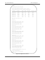
Modify Transceiver Settings
Enter Plug-In Type [All]: HD-XCVR
Enter Starting Plug-In Location [LET-1-1]: LET-1-10
Enter Ending Plug-In Location [RST1-8-22]: LET-1-10
------------------------------------------------------------------------------Location: LET-1-10
Plug-In: HD-XCVR
Groomed Service: Disabled
Edit this card? [No]: Yes
Groomed Service? [No]: Yes
Enable Timing Source? [No]: No
PCM30 Or PCM31 [PCM30]: PCM30
FPGA Remote Loopback [Disable]: Disable
FPGA Local Loopback [Disable]: Disable
xDSL Remote Loopback [Disable]: Disable
xDSL Local Loopback [Disable]: Disable
Far End FE1-HDSL(E1-HDSL) Setting:
Enter Line Coding [HDB3]: HDB3
Timeslot Assignment:
Assignment All Timeslots To Port [No Change]: Port 3
Timeslot Number [1]: 1
Port [Port 3]: Port 1
Continuous [Yes]: Yes
Timeslot Number [2]: 2
Port [Port 3]: Port 2
Continuous [Yes]: No
Effect Changes? [Yes]: Yes
Transceiver Settings Menu
MJ>>> [2]: 1
Figure 3-m. HD-XCVR Modify Transceiver Setting Menu
F/N: C10-41021001 Rev:1F
32
HTC-1100E Craft Interface
Hitron Technology Inc.
3.57.
When all card slots falling in the specified range have been searched and any located transceiver card settings have been established, the system returns to the Transceiver Settings Menu prompt.
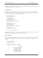
List BER Thresholds
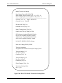
3.58.
The List BER Thresholds command allows the user to list all BER thresholds that are currently set for the
transceiver cards in the system. The alarm information is generated by the transmission card as it constantly monitors both data bits and CRC violations. The collected data is used to calculate a Bit Error Rate. The BER is calculated for each end of the transmission span on the receive data. The system operator may specify the Bit Error
Rate where specific alarms are to be reported. Two BER alarms are currently supported, the BER Red alarm and
the BER Maintenance alarm. The BER Red alarm indicates that the facility is no longer able to carry traffic. The
default value for this alarm is 10-3 for fiber and 10-4 for E1 transceivers. When the system detects a BER at this
threshold level for the corresponding transceiver, the facility is taken out of service. In addition to the system offer
other performance data: ES(Error Second), SES(Severe Error Second), UAS (unavailable Second), the interval of
record have 15 mins, 24 hours and 7 days.
List BER Thresholds
E1 Thresholds
BER - Red Alarm
: 10-4
BER - Maintenance Alarm: 10-6
15 minutes ES : 900
15 minutes SES: 900
15 minutes UAS: 900
24 hours ES
: 86400
24 hours SES : 86400
24 hours UAS : 86400
7 days ES
: 604800
7 days SES
: 604800
7 days UAS
: 604800
E3 Thresholds
BER - Red Alarm
: 10-3
BER - Maintenance Alarm: 10-8
Fiber Thresholds
BER - Red Alarm
F/N: C10-41021001 Rev:1F
: 10-3
33
HTC-1100E Craft Interface
Hitron Technology Inc.
Figure 3-n Sample Printout from the List BER Thresholds Commands
3.59.
If a redundant facility is available, service is concentrated onto it. Otherwise, trunk conditioning is initiated. The BER Red alarm is a Major alarm if no protection is available; it is a Minor alarm if redundant facilities
are available for service concentration. The BER Maintenance alarm indicates that the facility service is degraded.
The BER Maintenance alarm default threshold is 10-6 for fiber and E3 and 10-8 for El transceivers. The BER Maintenance alarm is always reported as a minor alarm.
3.60.
To list the current BER threshold settings, type {3} at the prompt and press {ENTER}. The BER thresholds for E1 and fiber transceivers will be listed. Figure 3-l shows the default BER thresholds listed when the List
BER Thresholds command is executed.
Modify BER Thresholds
3.61.
The Modify BER Thresholds command allows the user to change the alarm threshold settings for a specific
transmission medium. To modify the BER thresholds, type {4} at the Transceiver Settings Menu prompt and press
{ENTER}. The system then prompts the user for the type of facility to be modified. The default facility type is
E1.
Enter Facility Type [El]:
3.62.
Type the facility type at the prompt and press{ENTER}. If the {ENTER} key is pressed without specifying
a facility type, the system uses the default value, E1. If the user wishes to see the available facility types, pressing
either the {[} or {]} keys at the system prompt will scroll through the available facility types. Press {ENTER}
when the desired facility is displayed at the prompt.
3.63.
After entering the facility type, the system then prompts the user for the new BER thresholds to be used for
the specified facility. Table 3-B shows a list of the range of values to be used for the different transmission facilities available in the HTC-1100E.
Type
Alarm Type
Fiber/E3 Red
Maintenance
E1
Red
Maintenance
Inputs Allowed
10-3 to 10-9
10-4 to 10-10
10-3 to 10-7
10-5 to 10-8
Table 3-B. Alarm Threshold Ranges for HTC-1100E Transceiver Cards
F/N: C10-41021001 Rev:1F
34
HTC-1100E Craft Interface
Hitron Technology Inc.
3.64.
The first alarm threshold is the BER - Red Alarm. This alarm threshold specifies the Bit Error Rate at
which a Major or Critical alarm should be generated. Such an alarm would indicate that the system is experiencing
such a degradation in transmission that it is no longer able to carry traffic. For example, if the user wants a BER
Red Alarm to be triggered when the BER reaches 1 x 10⁻⁴, the user should enter the number {4} at the BER - Red
Alarm prompt.
BER - Red Alarm [10-4]: 103.65.
The default threshold for the selected facility (E1 in this case) appears in brackets and is selected by pressing {ENTER} at the prompt. If the number entered is not valid, the system will display an error message identifying the error. Correct the error by entering a correct value at the prompt and pressing {ENTER}. When a correct
value has been entered for the BER - Red Alarm, the system prompts for the alarm threshold value for the BER Maintenance Alarm.
BER - Maintenance Alarm [10-6]: 103.66.
At the prompt, enter the appropriate power of ten to be used as the BER alarm threshold that will trigger a
maintenance alarm and press {ENTER}. The default threshold for the selected facility (E1 in this case) appears in
brackets and is selected by pressing {ENTER}. This value should indicate that the system is experiencing sufficient errors in transmission that the system is in imminent danger of failure. If an incorrect value is entered, the
system will display an error message identifying the problem. Enter a value in the appropriate range and press
{ENTER}. When a correct value for the BER Maintenance Alarm threshold has been entered, the system will set
the BER thresholds and display the message Alarm Thresholds Modified before returning to the Transceiver Setting
Sub-menu.
3.67
The system also offers these performance data of E1X-XCVR card:ES、SES and UAS. These data indicate
user about the transmission status. There are their definitions:
Item
Definition
ES(Error Second)
A one second period with one or more errored blocks or at least one defect
SES(Severe Error
A one-second period which contains ≥30% errored blocks or at least one defect. SES is a
Second)
subset of ES.
UAS(Unavailable
A period of unavailable time begins at the onset of ten consecutive SES events. These ten
Second)
seconds are considered to be part of unavailable time.
Note: errored block (EB) means A block in which one or more bits are in error.
The system defined ES alarm is minor alarm. SES alarm is major alarm. UAS alarm is critical alarm. The intervals of
record have 15 minutes, 24 hours, 7 days. After 15 minutes, the system will move the performance data from 15
minutes record memory to 24 hours record memory. After 24 hours, the system will move the performance data from
24 hours record memory to 7 days record memory.
The default threshold for the selected facility appears in brackets and is selected by pressing “ENTER” at the prompt.
If the number entered is not valid, the system will display an error message identifying the error. Correct the error by
entering a correct value at the prompt and pressing “ENTER”.
F/N: C10-41021001 Rev:1F
35
HTC-1100E Craft Interface
Hitron Technology Inc.
Modify BER Thresholds
Enter Facility Type [E1]: E1
BER - Red Alarm
[10-4]: 10-4
BER - Maintenance Alarm [10-6]: 10-6
15 minutes ES [900]: 300
15 minutes SES [900]: 300
15 minutes UAS [900]: 300
24 hours ES
[86400]: 10000
24 hours SES
[86400]: 10000
24 hours UAS
[86400]: 10000
7 days ES
[604800]: 300000
7 days SES
[604800]: 300000
7 days UAS
[604800]: 300000
Figure 3-o. Sample Printout from the Modify BER Thresholds Commands
3.68.
From any menu in the system, the "A" command is available. To list all alarms, type {A} at the Transceiver Setting Sub-menu prompt and press {ENTER}.
3.69.
To return to the Provisioning Menu, type {B} at the Transceiver Setting Sub-menu prompt and press
{ENTER}.
3.70.
To return to the Main Menu, type {*} at the Transceiver Setting Sub-menu prompt and press {ENTER}.
3.71.
To get current menu list with the commands in the Transceiver Setting Sub-menu, type {?} at the Transceiver Setting Sub-menu prompt and press {ENTER}.
F/N: C10-41021001 Rev:1F
36
HTC-1100E Craft Interface
Hitron Technology Inc.
The DCS Provisioning Sub-menu
3.72.
The DCS Provisioning Sub-menu is used to specify the attributes of groomed E1 channels. This menu defines the carrier group alarm trunk conditioning signaling definitions and the idle code or mux code for individual
channels. The DCS provisioning menu can be used to specify the plug-in type, mux code, idle signaling and busy
signaling.
3.73.
When the HTC-1100E system detects a failure of the incoming signal and data, the system freezes the data
and signal at the last valid state. Then, 2.5 seconds after the failure is detected, the system transmits the idle signaling pattern in the signaling bits and the mux code in the data bits. The system begins sending the busy signal 2.5
seconds after sending the idle signal, and continues sending the busy signal for the duration of the fault. The mux
code is sent in the data bits for the duration of the fault - The idle and busy signal and mux code are user configurable and should be selected based on the use of the respective channels. AIS (alarm indication signal) is specified
by the CCITT for all fault conditions. Under normal conditions, there is not need to change any settings in the
DCS menus.
3.74.
The DCS provisioning menu is used to define the attributes of groomed E1 channels. It is not used to define a channel as a groomed E1. To define a channel as a groomed E1, use the Transceiver Settings Menu. To
map a groomed E1 channel, use the Modify Groomed Cross-Connects options of the Cross-Connect Menu. Channels may be configured on an individual basis, i.e., the first channel on the E1 may be POTS and the second channel
may be digital data. Figure 3-k shows the DCS Provisioning Sub-menu. To use the commands on this menu, type
{5} at the Provisioning menu prompt and press {ENTER}.
THU MAR 12, 1998
HTC-1100E LET
14:48:45
DCS Provisioning Menu
1. List Channel Attributes
2. Modify Channel Attributes
A. All Current Alarms
B. Provisioning Menu
*
Main Menu
?
Help
System Configuration Menu
>>> [1]:
Figure 3-p. HTC-1100E Craft Interface DCS Provisioning Sub-menu
F/N: C10-41021001 Rev:1F
37
HTC-1100E Craft Interface
Hitron Technology Inc.
List Channel Attributes
3.75.
The List Channel Attributes Command allows the user to list the current attributes for a specific groomed
E1 span. To use this command, type {1} at the DCS Provisioning Sub-menu prompt and press {ENTER}. The
system will prompt for the shelf-slot-circuit plug-in location of the groomed E1.
Enter Plug-In Location [LET-1-1-1] :
3.76.
Type the shelf-slot-circuit location of the E1 card. If the location contains a groomed E1, the system will
print a report listing the attributes of the specified channels. Before the first time setting, to list Channel Attributes
will get “ Has Not been Provisioned”.
Location: LET-1-1-1
Plug-In: E1X-XCVR
Mux Code: FF
Idle Signaling: 1111
Busy Signaling: 1111
3.77.
If the location does not contain a groomed E1 card, the system will report an error.
Plug-In Location Has No Circuits
3.78.
When the report is completed, the system returns to the DCS Provisioning Sub-menu prompt.
Modify Channel Attributes
3.79.
The Modify Channel Attributes Command is used to establish the attributes for a groomed E1 channel. To
use this command, type {2} at the DCS Provisioning Sub-menu prompt and press {ENTER}. The system will
prompt for the shelf-slot-circuit plug-in location of the groomed E1.
Enter Plug-In Location [LET-1-1-1]: LET-1-1-1
3.80.
At the prompt, type the shelf-slot-circuit location of the E1 card channel number carrying the groomed circuit to be configured and press {ENTER}. The system will prompt for the attributes to configure a specific channel
or channels.
3.81.
After a correct location is entered, the system prompts for the mux code. This option specifies the
eight-bit pattern that will be transmitted in the data bits 2.5 seconds after the failure of the E1 span.- At the prompt,
type the desired mux code (two hex digits) and press {ENTER}. The default mux code is hex FF (AIS or 1111).
Enter Mux Code [FF]:
3.82.
The user is next prompted for the idle signaling to be used. This option specifies the four-bit pattern that
will be transmitted 2.5 seconds after the failure of the E1 span. At the prompt, type the desired idle signaling pattern and press {ENTER}. The default pattern is 1111.
Enter Idle Signaling [1111]:
F/N: C10-41021001 Rev:1F
38
HTC-1100E Craft Interface
Hitron Technology Inc.
3.83.
Next, the user is prompted for the busy signaling to be used. This option specifies the four-bit pattern that
will be transmitted 2.5 seconds after the idle code is sent. Then the busy signal will continue for the duration of the
E1 span failure. At the prompt, type the desired busy signaling pattern and press {ENTER}. The default pattern
is 1111.
Enter Busy Signaling [1111]:
3.84.
If the plug-in location typed at the initial prompt does not contain a E1 configured for groomed circuits, the
system displays the following error message.
Plug-In Location Has No Circuits
3.85.
To define a channel as a groomed E1, use the Modify Transceiver Settings options of the Transceiver Settings Menu.
3.86.
When DCS modifications are complete, the system will print a message confirming that the settings have
been made and return to the DCS Provisioning Sub-menu prompt.
3.87.
From any menu in the system, the "A" command is available. To list all alarms, type {A} at the DCS Provisioning Sub-menu prompt and press {ENTER}.
3.88.
To return to the Provisioning Menu, type {B} at the DCS Provisioning Sub-menu prompt and press
{ENTER}.
3.89.
To return to the Main Menu, type {*} at the DCS Provisioning Sub-menu prompt and press {ENTER}.
3.90.
To current menu list help with the commands in the DCS Provisioning Sub-menu, type {?} at the DCS Provisioning Sub-menu prompt and press {ENTER}.
The Special Circuits Settings Sub-menu
3.91.
The Special Circuits Settings sub-menu contains commands used to provision the different types of special
cards used in the HTC-1100E . Commands are provided for provisioning both analog and digital cards. To use
the commands of the Special Circuits Settings sub-menu, type {6} at the Provisioning Menu prompt and press
{ENTER}. The system displays the Special Circuits Settings sub-menu shown in the next figure.
Tue Dec 7, 1999
HTC LET
11:57:31
Special Circuits Settings Menu
1. List Analog Circuit Settings
2. Modify Analog Circuit Settings
3. List Digital Circuit Settings
4. Modify Digital Circuit Settings
F/N: C10-41021001 Rev:1F
39
5. List V5 Circuit Settings
HTC-1100E Craft Interface
Hitron Technology Inc.
Figure 3-q HTC-1100E Craft Interface Special Circuits Settings Sub-menu
List Analog Circuit Settings
3.92.
The List Analog Circuit Settings command allows the user to list the settings for analog cards in the system.
When this command is issued, the system prints a report of the analog circuit settings similar to the report shown in
figure 3-n. To use the List Analog Circuit Settings command, type {1} at the Circuit Settings sub-menu prompt and
press {ENTER}.
3.93.
The system prompts the user for a Plug-in card type. This card type may be All, DPO, DPT, E&M,
L-PAY, L-UVG, R-PAY, R-UVG, SLC-E, SLC-T, TO. At the prompt, type the desired card type and press
{ENTER}.
Enter Plug-In Type [All]:
3.94.
After the plug-in type has been entered, the system prompts the user for a starting location. The starting
location is the terminal-shelf-slot-circuit location where the user wishes the report to begin. At the prompt, type the
desired starting location and press {ENTER}
Enter Starting Plug-in Location [LET-1-1-1]: LET-1-1
3.95.
The system now prompts the user for an ending location. The ending location is the terminal-shelf-slot-circuit location where the user wishes the report to end. At the prompt, type the desired location and
press {ENTER}.
Enter Ending Plug-In Location [RST1-8-26]: RST1-8-26
3.96.
After the ending location has been entered. the system prints the report and returns the user to the Circuit
Settings sub-menu.
List Analog Circuit Settings
Enter Plug-In Type [All]: All
Enter Starting Plug-In Location [LET-1-1]: LET-1-1
Enter Ending Plug-In Location [RST1-8-26]: RST1-8-26
Location
Plug-In
Mode
Type
LET-1-8
LET-1-8-1
LET-1-8-2
RST1-1-8
RST1-1-8-1
RST1-1-8-2
E&M
E&M
E&M
E&M
E&M
E&M
Interface
E&M I
E&M I
Interface
E&M I
E&M I
Type: 4Wire
>>>[1]:
TX Gain Misc
0.0dB
0.0dB
0.0dB
0.0dB
0.0dB
0.0dB
0.0dB
0.0dB
Type: 4Wire
Line Cards Listed:2
F/N: C10-41021001
Rev:1F Settings Menu
Special Circuits
RX Gain
40
HTC-1100E Craft Interface
Hitron Technology Inc.
Figure 3-r. Sample Output from the List Analog Circuits Settings Command
Modify Analog Circuit Settings
3.97.
The Modify Analog Circuit Settings command allows the user to change settings such as gain and attenuation on various analog plug-in cards. Table 3-C list the various settings available for each of the analog cards. To
establish or change the settings for an analog card, type {2} at the Circuit Settings sub-menu prompt and press
{ENTER}. Figure 3-p-1~3-p-7 shows a typical screen using the Modify Analog Circuit Settings command.
Card Type
E&M
Setting Item
Interface Type
Acceptable Values
Plug-In Mode
All、E&M I、E&M Ⅱ 、E&M Ⅲ、E&M Ⅳ、E&M Ⅴ 、PLR I、
4-Wire、2-Wire
PLRⅡ 、Tand I sta.、Tand I Swi. 、Tand Ⅱ sta.、Tand Ⅱ
Swi.、DX、TO
L-UVG
R-UVG
SLC-E
SLC-T
Signalling Type
D4、R2、KD4
RX Gain
4 Wire:-16~8;2 Wire:-10~0
TX Gain
4 Wire:-16~6;2 Wire:-4~4
AC Impedance
Auto、600 Ohms、900 Ohms
DC Resistance
Auto、200 Ohms、1000 Ohms
Plug-In Mode
GSLS、GS、LS
RX Gain
-9~3
TX Gain
-3~9
Plug-In Mode
GSLS、GS、LS
RX Gain
-9~3
TX Gain
-3~9
AC Impedance
Auto、600 Ohms、900 Ohms
DC Resistance
Auto、200 Ohms、1000 Ohms
Plug-In Mode
GSLS、GS、LS
Signalling Type
R2、KD4
RX Gain
-9~3
TX Gain
-3~9
Plug-In Mode
GSLS、GS、LS
Signalling Type
R2、KD4
RX Gain
-9~3
TX Gain
-3~9
F/N: C10-41021001 Rev:1F
41
HTC-1100E Craft Interface
Card Type
DPT
DPO
Hitron Technology Inc.
Setting Item
AC Impedance
Acceptable Values
DC Resistance
Auto、200 Ohms、1000 Ohms
Plug-In Mode
GSLS、GS、LS
Signalling Type
R2、KD4
RX Gain
-9~3
TX Gain
-3~9
Plug-In Mode
GSLS、GS、LS
Signalling Type
R2、KD4
RX Gain
-9~3
TX Gain
Auto、600 Ohms、900 Ohms
-3~9
Table 3-C.
Settings for Analog Cards
Note: When using the E&M cards, wiring configurations on the backplane will limit the combinations of settings
which can be used in the software provisioning of this card.
3.98.
The system prompts the user for the plug-in type. The analog cards (SLC-E, SLC-T, DPO, DPT, L-UVG,
R-UVG and E&M) may be set using this command. At the prompt, type the card type to be set and press
{ENTER}.
Enter Plug-In Type [E&M]: E&M
3.99.
The user is now prompted for a beginning circuit location. This location is the terminal-shelf-slot-circuit
location of the first circuit the user wishes to set. At the prompt, type the desired location and press {ENTER}.
Enter Starting Circuit Location [LET-1-1-1]: LET-1-1
3.100. The user is now prompted for an ending circuit location.
This location is the last terminal-shelf-slot-circuit location the user wishes to set with this command. At the prompt, type the desired location
and press {ENTER}.
Enter Ending Circuit Location [RST1-8-26]: RST1-8-26
3.101. After the ending location has been specified, the system begins at the starting location and searches the slots
for cards matching the card type specified. When a matching card is found, the system lists the current configuration information for that card and asks the user if this card is to be edited.
Edit This Card? [Yes]:
3.102 Depending upon the card type specified above, the user will now be prompted for the configuration information for the card. At the prompt or prompts displayed, type the appropriate information and press {ENTER}.
The prompts will ask for information such as gain, attenuation and other settings that are specific to the card type
F/N: C10-41021001 Rev:1F
42
HTC-1100E Craft Interface
Hitron Technology Inc.
being configured. For each card, selecting specific settings for that card may restrict the user's available choices for
other settings on that card. Selecting "Auto" when that choice is available causes the system to set certain settings
to predefined settings which are listed in the settings options tables for each card.
3.103 After the configuration settings have been entered, the system asks if the current settings are to be overwritten. If the new values are to be used as the new settings for this card, type {Yes} and press {ENTER}. If the
old, values are to be used, type {No} at the prompt and press {ENTER} to discard the changes. If "No" is specified,
the system continues the search for the next matching card of the specified type. The user must execute this command again to edit entries made to the card settings.After the configuration settings are completed, the system returns the user to the Circuit Settings sub-menu prompt.
3.104 After the configuration settings are completed, the system returns the user to the Circuit Setting sub-menu
prompt.
Modify Analog Circuit Settings
Enter Plug-In Type [All]:E&M
Enter Starting Plug-In Location [LET-1-1]:LET-1-1
Enter Ending Plug-In Location [RST1-8-26]:RST1-8-26
Location
LET-1-10
LET-1-10-1
LET-1-10-2
Plug-In
E&M
E&M
E&M
Mode
Type
RX Gain
Interface Type: 4 Wire
E&M I
D4
0.0 dB
E&M I
D4
0.0 dB
Edit this card? [Yes]: Yes
LET-1-10
Enter Interface Type [4 Wire]: 4 Wire
LET-1-10-1
Enter Plug-In Mode [E&M I]: E&M I
Enter Signalling Type [D4]: D4
Enter RX Gain [0.0]: 0.0
Enter TX Gain [0.0]: 0.0
LET-1-10-2
Enter Plug-In Mode [E&M I]: TO
Enter Signalling Type [D4]: D4
Enter RX Gain [0.0]: 0.0
Enter TX Gain [0.0]: 0.0
Overwrite Current Setting? [Yes]: Yes
Line Cards Modified: 1
Special Circuits Settings Menu
MJ>>> [2]:
Figure 3-r-1 Sample Screen of E &M
F/N: C10-41021001 Rev:1F
43
TX Gain
0.0 dB
0.0 dB
Misc
HTC-1100E Craft Interface
Hitron Technology Inc.
Modify Analog Circuit Settings
Enter Plug-In Type [All]:L-UVG
Enter Starting Plug-In Location [LET-1-1]:LET-1-1
Enter Ending Plug-In Location [RST1-8-26]:RST1-8-26
Location
LET-1-10
LET-1-10-1
LET-1-10-2
LET-1-10-3
LET-1-10-4
LET-1-10-5
LET-1-10-6
Plug-In
L-UVG
L-UVG
L-UVG
L-UVG
L-UVG
L-UVG
L-UVG
Mode
Type
AC Impedance: Auto
GSLS
GSLS
GSLS
GSLS
GSLS
GSLS
RX Gain
DC Resistance: Auto
Auto
Auto
Auto
Auto
Auto
Auto
Auto
Auto
Auto
Auto
Auto
Auto
Edit this card? [Yes]: Yes
LET-1-10
Enter AC Impedance [Auto]: Auto
Enter DC Resistance [Auto]: Auto
LET-1-10-1
Enter Plug-In Mode [GSLS]: GSLS
Enter RX Gain [Auto]: Auto
Enter TX Gain [Auto]: Auto
LET-1-10-2
Enter Plug-In Mode [GSLS]: GSLS
Enter RX Gain [Auto]: Auto
Enter TX Gain [Auto]: Auto
LET-1-10-3
Enter Plug-In Mode [GSLS]: GSLS
Enter RX Gain [Auto]: Auto
Enter TX Gain [Auto]: Auto
LET-1-10-4
Enter Plug-In Mode [GSLS]: GSLS
Enter RX Gain [Auto]: Auto
Enter TX Gain [Auto]: Auto
LET-1-10-5
Enter Plug-In Mode [GSLS]: GSLS
Enter RX Gain [Auto]: Auto
Enter TX Gain [Auto]: Auto
LET-1-10-6
Enter Plug-In Mode [GSLS]: GSLS
Enter RX Gain [Auto]: Auto
Enter TX Gain [Auto]: Auto
Overwrite Current Setting? [Yes]: Yes
Line Cards Modified: 1
Special Circuits Settings Menu
MJ>>> [2]:
Figure 3-s-2 Sample Screen of L-UVG
F/N: C10-41021001 Rev:1F
44
TX Gain Misc
HTC-1100E Craft Interface
Hitron Technology Inc.
Modify Analog Circuit Settings
Enter Plug-In Type [All]:R-UVG
Enter Starting Plug-In Location [LET-1-1]:LET-1-1
Enter Ending Plug-In Location [RST1-8-26]:RST1-8-26
Location
LET-1-10-1
LET-1-10-2
LET-1-10-3
LET-1-10-4
LET-1-10-5
LET-1-10-6
Plug-In
Mode
R-UVG
R-UVG
R-UVG
R-UVG
R-UVG
R-UVG
GSLS
GSLS
GSLS
GSLS
GSLS
GSLS
Type
RX Gain
TX Gain
Auto
Auto
Auto
Auto
Auto
Auto
Auto
Auto
Auto
Auto
Auto
Auto
Edit this card? [Yes]: Yes
LET-1-10
LET-1-10-1
Enter Plug-In Mode [GSLS]: GSLS
Enter RX Gain [Auto]: Auto
Enter TX Gain [Auto]: Auto
LET-1-10-2
Enter Plug-In Mode [GSLS]: GSLS
Enter RX Gain [Auto]: Auto
Enter TX Gain [Auto]: Auto
LET-1-10-3
Enter Plug-In Mode [GSLS]: GSLS
Enter RX Gain [Auto]: Auto
Enter TX Gain [Auto]: Auto
LET-1-10-4
Enter Plug-In Mode [GSLS]: GSLS
Enter RX Gain [Auto]: Auto
Enter TX Gain [Auto]: Auto
LET-1-10-5
Enter Plug-In Mode [GSLS]: GSLS
Enter RX Gain [Auto]: Auto
Enter TX Gain [Auto]: Auto
LET-1-10-6
Enter Plug-In Mode [GSLS]: GSLS
Enter RX Gain [Auto]: Auto
Enter TX Gain [Auto]: Auto
Overwrite Current Setting? [Yes]: Yes
Line Cards Modified: 1
Special Circuits Settings Menu
MJ>>> [2]:
Figure 3-s-3 Sample Screen of R-UVG
F/N: C10-41021001 Rev:1F
45
Misc
HTC-1100E Craft Interface
Hitron Technology Inc.
Modify Analog Circuit Settings
Enter Plug-In Type [All]:SLC-E
Enter Starting Plug-In Location [LET-1-1]:LET-1-1
Enter Ending Plug-In Location [RST1-8-26]:RST1-8-26
Location
LET-1-10
LET-1-10-1
LET-1-10-2
LET-1-10-3
LET-1-10-4
LET-1-10-5
LET-1-10-6
Plug-In
SLC-E
SLC-E
SLC-E
SLC-E
SLC-E
SLC-E
SLC-E
Mode
Type
AC Impedance: Auto
GSLS
R2
GSLS
R2
GSLS
R2
GSLS
R2
GSLS
R2
GSLS
R2
RX Gain
DC Resistance: Auto
Auto
Auto
Auto
Auto
Auto
Auto
Auto
Auto
Auto
Auto
Auto
Auto
Edit this card? [Yes]: Yes
LET-1-10
Enter AC Impedance [Auto]: Auto
Enter DC Resistance [Auto]: Auto
LET-1-10-1
Enter
Enter
Enter
Enter
Plug-In Mode [GSLS]: GSLS
Signalling Type [R2]: R2
RX Gain [Auto]: Auto
TX Gain [Auto]: Auto
LET-1-10-2
Enter
Enter
Enter
Enter
Plug-In Mode [GSLS]: GSLS
Signalling Type [R2]: R2
RX Gain [Auto]: Auto
TX Gain [Auto]: Auto
LET-1-10-3
Enter
Enter
Enter
Enter
Plug-In Mode [GSLS]: GSLS
Signalling Type [R2]: R2
RX Gain [Auto]: Auto
TX Gain [Auto]: Auto
LET-1-10-4
Enter
Enter
Enter
Enter
Plug-In Mode [GSLS]: GSLS
Signalling Type [R2]: R2
RX Gain [Auto]: Auto
TX Gain [Auto]: Auto
LET-1-10-5
Enter
Enter
Enter
Enter
Plug-In Mode [GSLS]: GSLS
Signalling Type [R2]: R2
RX Gain [Auto]: Auto
TX Gain [Auto]: Auto
LET-1-10-6
Enter
Enter
Enter
Enter
Plug-In Mode [GSLS]: GSLS
Signalling Type [R2]: R2
RX Gain [Auto]: Auto
TX Gain [Auto]: Auto
Overwrite Current Setting? [Yes]: Yes
Line Cards Modified: 1
Special Circuits Settings Menu
MJ>>> [2]:
Figure 3-r-4 Sample Screen of SLC-E
F/N: C10-41021001 Rev:1F
46
TX Gain
Misc
HTC-1100E Craft Interface
Hitron Technology Inc.
Modify Analog Circuit Settings
Enter Plug-In Type [All]:SLC-T
Enter Starting Plug-In Location [LET-1-1]:LET-1-1
Enter Ending Plug-In Location [RST1-8-26]:RST1-8-26
Location
LET-1-10-1
LET-1-10-2
LET-1-10-3
LET-1-10-4
LET-1-10-5
LET-1-10-6
Plug-In
Mode
Type
RX Gain
TX Gain
SLC-T
SLC-T
SLC-T
SLC-T
SLC-T
SLC-T
GSLS
GSLS
GSLS
GSLS
GSLS
GSLS
R2
R2
R2
R2
R2
R2
Auto
Auto
Auto
Auto
Auto
Auto
Auto
Auto
Auto
Auto
Auto
Auto
Edit this card? [Yes]: Yes
LET-1-10
LET-1-10-1
Enter
Enter
Enter
Enter
Plug-In Mode [GSLS]: GSLS
Signalling Type [R2]: R2
RX Gain [Auto]: Auto
TX Gain [Auto]: Auto
LET-1-10-2
Enter
Enter
Enter
Enter
Plug-In Mode [GSLS]: GSLS
Signalling Type [R2]: R2
RX Gain [Auto]: Auto
TX Gain [Auto]: Auto
LET-1-10-3
Enter
Enter
Enter
Enter
Plug-In Mode [GSLS]: GSLS
Signalling Type [R2]: R2
RX Gain [Auto]: Auto
TX Gain [Auto]: Auto
LET-1-10-4
Enter
Enter
Enter
Enter
Plug-In Mode [GSLS]: GSLS
Signalling Type [R2]: R2
RX Gain [Auto]: Auto
TX Gain [Auto]: Auto
LET-1-10-5
Enter
Enter
Enter
Enter
Plug-In Mode [GSLS]: GSLS
Signalling Type [R2]: R2
RX Gain [Auto]: Auto
TX Gain [Auto]: Auto
LET-1-10-6
Enter
Enter
Enter
Enter
Plug-In Mode [GSLS]: GSLS
Signalling Type [R2]: R2
RX Gain [Auto]: Auto
TX Gain [Auto]: Auto
Overwrite Current Setting? [Yes]: Yes
Line Cards Modified: 1
Special Circuits Settings Menu
MJ>>> [2]:
Figure3-r-5 Sample Screen of SLC-T
F/N: C10-41021001 Rev:1F
47
Misc
HTC-1100E Craft Interface
Hitron Technology Inc.
Modify Analog Circuit Settings
Enter Plug-In Type [All]:DPT
Enter Starting Plug-In Location [LET-1-1]:LET-1-1
Enter Ending Plug-In Location [RST1-8-26]:RST1-8-26
Location
LET-1-10
LET-1-10-1
LET-1-10-2
LET-1-10-3
LET-1-10-4
LET-1-10-5
LET-1-10-6
Plug-In
DPT
DPT
DPT
DPT
DPT
DPT
DPT
Mode
Type
AC Impedance: Auto
GSLS
R2
GSLS
R2
GSLS
R2
GSLS
R2
GSLS
R2
GSLS
R2
RX Gain
DC Resistance: Auto
Auto
Auto
Auto
Auto
Auto
Auto
Auto
Auto
Auto
Auto
Auto
Auto
Edit this card? [Yes]: Yes
LET-1-10
Enter AC Impedance [Auto]: Auto
Enter DC Resistance [Auto]: Auto
LET-1-10-1
Enter
Enter
Enter
Enter
Plug-In Mode [GSLS]: GSLS
Signalling Type [R2]: R2
RX Gain [Auto]: Auto
TX Gain [Auto]: Auto
LET-1-10-2
Enter
Enter
Enter
Enter
Plug-In Mode [GSLS]: GSLS
Signalling Type [R2]: R2
RX Gain [Auto]: Auto
TX Gain [Auto]: Auto
LET-1-10-3
Enter
Enter
Enter
Enter
Plug-In Mode [GSLS]: GSLS
Signalling Type [R2]: R2
RX Gain [Auto]: Auto
TX Gain [Auto]: Auto
LET-1-10-4
Enter
Enter
Enter
Enter
Plug-In Mode [GSLS]: GSLS
Signalling Type [R2]: R2
RX Gain [Auto]: Auto
TX Gain [Auto]: Auto
LET-1-10-5
Enter
Enter
Enter
Enter
Plug-In Mode [GSLS]: GSLS
Signalling Type [R2]: R2
RX Gain [Auto]: Auto
TX Gain [Auto]: Auto
LET-1-10-6
Enter
Enter
Enter
Enter
Plug-In Mode [GSLS]: GSLS
Signalling Type [R2]: R2
RX Gain [Auto]: Auto
TX Gain [Auto]: Auto
Overwrite Current Setting? [Yes]: Yes
Line Cards Modified: 1
Special Circuits Settings Menu
MJ>>> [2]:
Figure 3-r-6 Sample Screen of SLC-T
F/N: C10-41021001 Rev:1F
48
TX Gain
Misc
HTC-1100E Craft Interface
Hitron Technology Inc.
Modify Analog Circuit Settings
Enter Plug-In Type [All]:DPO
Enter Starting Plug-In Location [LET-1-1]:LET-1-1
Enter Ending Plug-In Location [RST1-8-26]:RST1-8-26
Location
LET-1-10-1
LET-1-10-2
LET-1-10-3
LET-1-10-4
LET-1-10-5
LET-1-10-6
Plug-In
Mode
Type
RX Gain
TX Gain
DPO
DPO
DPO
DPO
DPO
DPO
GSLS
GSLS
GSLS
GSLS
GSLS
GSLS
R2
R2
R2
R2
R2
R2
Auto
Auto
Auto
Auto
Auto
Auto
Auto
Auto
Auto
Auto
Auto
Auto
Edit this card? [Yes]: Yes
LET-1-10
LET-1-10-1
Enter
Enter
Enter
Enter
Plug-In Mode [GSLS]: GSLS
Signalling Type [R2]: R2
RX Gain [Auto]: Auto
TX Gain [Auto]: Auto
LET-1-10-2
Enter
Enter
Enter
Enter
Plug-In Mode [GSLS]: GSLS
Signalling Type [R2]: R2
RX Gain [Auto]: Auto
TX Gain [Auto]: Auto
LET-1-10-3
Enter
Enter
Enter
Enter
Plug-In Mode [GSLS]: GSLS
Signalling Type [R2]: R2
RX Gain [Auto]: Auto
TX Gain [Auto]: Auto
LET-1-10-4
Enter
Enter
Enter
Enter
Plug-In Mode [GSLS]: GSLS
Signalling Type [R2]: R2
RX Gain [Auto]: Auto
TX Gain [Auto]: Auto
LET-1-10-5
Enter
Enter
Enter
Enter
Plug-In Mode [GSLS]: GSLS
Signalling Type [R2]: R2
RX Gain [Auto]: Auto
TX Gain [Auto]: Auto
LET-1-10-6
Enter
Enter
Enter
Enter
Plug-In Mode [GSLS]: GSLS
Signalling Type [R2]: R2
RX Gain [Auto]: Auto
TX Gain [Auto]: Auto
Overwrite Current Setting? [Yes]: Yes
Line Cards Modified: 1
Special Circuits Settings Menu
MJ>>> [2]:
Figure 3-r-7 Sample Screen of DPO
F/N: C10-41021001 Rev:1F
49
Misc
HTC-1100E Craft Interface
Hitron Technology Inc.
List Digital Circuit Settings
3.105. The List Digital Circuit Settings command allows the user to list the settings for the digital cards in the system. To use this command type {3} at the Circuit Settings sub-menu and press {ENTER}. Figure 3-q shows a sample printout using this command
3.106. The system prompts the user for the plug-in type. The settings for digital cards may be listed using this
command. The digital cards may not be configured using this command. At the prompt, type the card type to be
set and press {ENTER}.
Enter Plug-In Type [All]:
3.107. The user is now prompted for a beginning and an ending circuit location. This location is the terminal-shelf-slot-circuit location of the first and last circuit the user wishes to set. At the prompt, type the desired location and press {ENTER}.
Enter Starting Plug-In Location [LET-1-1-1]: LET-1-1
Enter Ending Plug-In Location [RST1-8-26]: RST1-1-1
3.108. After the ending location has been entered, the system prints a report of the settings for all digital circuits
matching the specified type found between the starting and ending locations specified. When the report is completed, the system returns the user to the Special Circuits Settings sub-menu.
Modify Digital Circuit Settings
3.109. The Modify Digital Circuit Settings command allows the user to establish or change settings for the digital
circuits in the system. These commands are used only with digital cards. Analog cards are configured using the
Modify Analog Circuit Settings command discussed above. To use the Modify Digital Circuit Settings command,
type {4} at the Circuit Settings sub-menu prompt and press {ENTER}. Figure 3-r-1~3-r-10 shows a typical screen
using this command.
F/N: C10-41021001 Rev:1F
50
HTC-1100E Craft Interface
Hitron Technology Inc.
List Digital Circuit Settings
Enter Plug-In Type[All]: ALL
Enter Staring Plug-In Location﹝ LET-1-1﹞ :LET-1-1
Enter Ending Plug-In Location[RST1-8-26]: RST1-8-26
Location: LET-1-10
Plug-In: ADU
Circuit
Data Rate
Stop Bits
Character Length
1
2
9600 bps
9600 bps
1
1
8 Bits
8 Bits
Press Any key
Location: LET-1-15
Plug-In: CO64
Circuit
Line
Loopback
1
2
3
Disabled
Disabled
Enabled
Disabled
Disabled
Disabled
Press Any Key
Location: RST1-1-14
Plug-In: SDU
Interface Type: V.35
Data Rate: 64 Kbps
SYNC Char: 16
Press Any Key
Location: RST1-1-17
Plug-In: ADU
Circuit
Data Rate
Stop Bits
Character Length
1
2
9600 bps
9600 bps
1
1
8 Bits
8 Bits
Press Any key
Location: RST1-1-18
Plug-In: N64P
Interface Type: V.35
Data Rate: 1 * 64 Kbps
Remote Loopback
: No
Local loopback
: No
Line Cards Listed: 5
Special Circuits Setting Menu
Figure 3-s Sample Screen Using the List Digital Circuit Settings Command
F/N: C10-41021001 Rev:1F
51
HTC-1100E Craft Interface
Hitron Technology Inc.
Enter Plug-In Type [ADU]:ADU
Enter Starting Plug-In Location [LET-1-1]:LET-1-1
Enter Ending Plug-In Location [RST1-8-26]:RST1-8-26
Location: LET-1-10
Plug-In: ADU
Circuit
Data Rate
Stop Bits
1
2
9600 bps
9600 bps
1
1
Character Length
8 Bits
8 Bits
Edit this card? [Yes]: Yes
Location:LET-1-10
Plug-In: ADU
LET-1-10-1
Enter Data Rate [9600 bps]: 9600 bps
Enter Stop Bits [1]: 1
LET-1-10-2
Enter Data Rate [9600 bps]: 9600 bps
Enter Stop Bits [1]: 1
Overwrite Current Setting? [Yes]: Yes
Line Cards Modified: 1
Special Circuits Settings Menu
MJ>>> [4]:
Figure 3-s-1 Sample Screen of ADU
Choices of ADU setting item:
Edit This Card ?
[ Yes ]: Yes
…
Enter Data Rate:300/600/1200/4800/9600/19200/38400 bps
Enter Stop Bits:1
…
F/N: C10-41021001 Rev:1F
52
HTC-1100E Craft Interface
Hitron Technology Inc.
Modify Digital Circuit Settings
Enter Plug-In Type [All]:SDU
Enter Starting Plug-In Location [LET-1-1]:LET-1-1
Enter Ending Plug-In Location [RST1-8-26]:RST1-8-26
--------------------------------------------------Location: RST1-1-10
Plug-In: SDU
Interface Type: V.35
Data Rate: 56k bps
SYNC Char: 16
Edit this card? [Yes]: Yes
Location:RST1-1-10
Plug-In: SDU
Enter Interface Type [V.35]: V.35
Enter Data Rate [64kbps]:64k bps
Enter SYNC Code [16]:16
Overwrite Current Setting? [Yes]: Yes
Line Cards Modified: 1
Special Circuits Settings Menu
MJ>>> [4]:
Figure 3-s-2 Sample Screen of SDU
Choices of SDU setting item:
Edit This Card ?
[ Yes ]: Yes
…
Enter Interface Type:V.35/V.11/V.28
Enter Data Rate : 600/ 1200/ 2400/ 4800/ 9600/ 19.2 k/ 38.4 k/ 48 k/ 56 k/ 64 kbps
Enter SYNC Code:00~FF
…
F/N: C10-41021001 Rev:1F
53
HTC-1100E Craft Interface
Hitron Technology Inc.
Modify Digital Circuit Settings
Enter Plug-In Type [All]:CO64
Enter Starting Plug-In Location [LET-1-1]:LET-1-1
Enter Ending Plug-In Location [RST1-8-26]:RST1-8-26
Location: LET-1-10
Plug-In: CO64
Circuit
Line
Loopback
1
2
3
Enabled
Enabled
Enabled
Disabled
Disabled
Disabled
Edit this card? [Yes]: Yes
Location:LET-1-10
Plug-In: CO64
LET-1-10-1
Line Circuit [Disabled]: Enabled
Line Loopback [Disabled]: Disabled
LET-1-10-2
Line Circuit [Disabled]: Enabled
Line Loopback [Disabled]: Enabled
LET-1-10-3
Line Circuit [Enabled]: Disabled
Line Loopback [Disabled]: Disabled
Overwrite Current Setting? [Yes]: Yes
Line Cards Modified: 1
Special Circuits Settings Menu
MJ>>> [4]:
Figure 3-s-3 Sample Screen of CO64
Choices of CO64 setting item:
Edit This Card ?
[ Yes ]: Yes
…
Timing Source:Enabled /Disabled
…
Line Circuit:Disabled / Enabled
Line Loopback:Disabled /Enabled
F/N: C10-41021001 Rev:1F
54
HTC-1100E Craft Interface
Hitron Technology Inc.
…
Modify Digital Circuit Settings
Enter Plug-In Type [All]: DD64
Enter Staring Plug-In Location [LET-1-1]: LET-1-1
Enter Ending Plug-In Location [RST13-8-26]:RST13-8-26
Location: LET-1-10
Plug-In: DD64
Data Rate:64 Kbps
Error correction:Disabled
Remote Loopback:Disallow
Zero Code Suppression:Disabled
Edit this card? [Yes]: Yes
Location: LET-1-10
Plug-In: DD64
Enter Data Rate[64 kbps]:2400 bps
Error correction[Disabled]:Disabled
Remote Loopback[Disallow]:Disallow
Second Channel[Disabled]:Disabled
Enter DS0 Type[DS0-A]:DSO-A
Overwrite Current Setting? [Yes]: Yes
Line Cards Modified: 1
MJ >>> [4]:
Figure 3-s-4 Sample Screen of DD64
Choices of DD64 setting item:
Edit This Card ?
[ Yes ]: Yes
…
Enter Data Rate:2400 /4800 / 9600 / 19200 / 56000 / 64000
bps
Error Correction: Enabled / Disabled
Remote Loopback:Allow / Disallow
Zero Code Suppression:Enabled / Disabled (When data rate is under 56 kbps)
Second Channel:Enabled / Disabled (When data rate is under 56 kbps)
F/N: C10-41021001 Rev:1F
55
HTC-1100E Craft Interface
Hitron Technology Inc.
DS0-A/B:DS0-A
…
Modify Digital Circuit Settings
Enter Plug-In Type [All]: N64P
Enter Staring Plug-In Location [LET-1-1]: LET-1-1
Enter Ending Plug-In Location [RST13-8-26]:RST13-8-26
Location: LET-1-10
Plug-In: N64P
Timing Source: Disabled
Interface Type: V.35
Data Rate: 1×64 Kbps
Remote Loopback: Disabled
Local Loopback: Disabled
Edit this card? [Yes]: Yes
Location: LET-1-10
Plug-In: N64P
Timing Source: Disabled
Enter Interface Type[V.35]: V.36
Enter N×64 rate selection, N is [1]:30
Remote Loopback[Disabled]: Disabled
Local Loopback[Disabled]: Disabled
Overwrite Current Setting? [Yes]: Yes
Line Cards Modified: 1
MJ >>> [4]:
Figure 3-s-5 Sample Screen of N64P
Choices of N64P setting item:
Edit This Card ?
[ Yes ]: Yes
…
Timing Source:Enabled /Disabled Enter Interface Type:V.35 / V.36
Enter N ×64 rate selection ,N is :1~30
Remote Loop:Enabled / Disabled
Local Loop:Enabled / Disabled
F/N: C10-41021001 Rev:1F
56
HTC-1100E Craft Interface
Hitron Technology Inc.
…
Modify Digital Circuit Settings
Enter Plug-In Type [All]:LI-ISDN
Enter Starting Plug-In Location [LET-1-1]:LET-1-1
Enter Ending Plug-In Location [RST1-8-26]:RST1-8-26
Location: LET-1-10
Plug-In: LI-ISDN
Timing Source:Disabled
Circuit
Line Circuit
1
2
Disabled
Disabled
Edit this card? [Yes]: Yes
Location:LET-1-10
Plug-In: LI-ISDN
Timing Source[Disabled]:Enabled
LET-1-10-1
Line Circuit [Disabled]: Enabled
LET-1-10-2
Line Circuit [Disabled]: Enabled
Overwrite Current Setting? [Yes]: Yes
Line Cards Modified: 1
Special Circuits Settings Menu
MJ>>> [4]:
Figure 3-s-6 Sample Screen of LI-ISDN
Choices of LI-ISDN setting item:
Edit This Card ?
F/N: C10-41021001 Rev:1F
[ Yes ]: Yes
57
HTC-1100E Craft Interface
Hitron Technology Inc.
…
Timing Source:Enabled /Disabled
…
Line Circuit:Disable/Enable
…
Modify Digital Circuit Settings
Enter Plug-In Type [All]:RI-ISDN
Enter Starting Plug-In Location [LET-1-1]:LET-1-1
Enter Ending Plug-In Location [RST1-8-26]:RST1-8-26
Location: LET-1-10
Plug-In: RI-ISDN
V5 Provisioning:Disabled
Circuit
Line Circuit
1
2
Disabled
Disabled
Edit this card? [Yes]: Yes
Location:LET-1-10
Plug-In: RI-ISDN
V5 Provisioning[Disabled]:Disabled
LET-1-10-1
Line Circuit [Disabled]: Enabled
LET-1-10-2
Line Circuit [Disabled]: Enabled
Overwrite Current Setting? [Yes]: Yes
Line Cards Modified: 1
Special Circuits Settings Menu
MJ>>> [4]:
Figure 3-s-7 Sample Screen of RI-ISDN
Choices of RI-ISDN setting item:
F/N: C10-41021001 Rev:1F
58
HTC-1100E Craft Interface
Edit This Card ?
Hitron Technology Inc.
[ Yes ]: Yes
…
V5 Provisioning:Enabled /Disabled
…
Line Circuit:Disable/Enable
…
Modify Digital Circuit Settings
Enter Plug-In Type [All]:E1AX
Enter Starting Plug-In Location [LET-1-1]:LET-1-1
Enter Ending Plug-In Location [RST1-8-26]:RST1-8-26
Location: LET-1-10
Plug-In: E1AX
Local Loop : Disabled
Remote Loop: Disabled
Edit this card? [Yes]: Yes
Location:LET-1-10
Plug-In: E1AX
Local Loop [Disabled]: Enabled
Remote Loop [Disabled]: Disabled
Overwrite Current Setting? [Yes]: Yes
Line Cards Modified: 1
Special Circuits Settings Menu
MJ>>> [4]:
Figure 3-s-8 Sample Screen of E1AX
Choices of E1AX setting item:
Edit This Card ?
[ Yes ]: Yes
…
Local Loop:Enabled /Disabled
Remote Loop:Enabled /Disabled
…
F/N: C10-41021001 Rev:1F
59
HTC-1100E Craft Interface
F/N: C10-41021001 Rev:1F
Hitron Technology Inc.
60
HTC-1100E Craft Interface
Hitron Technology Inc.
Modify Transceiver Settings
Enter Plug-In Type [ALL]:E1X
Enter Starting Plug-In Location[LET-1-1]:LET-1-1
Enter Ending Plug-In Location[RST1-8-26]:RST1-8-26
LET-1-10 is a E1X
Enable Timing Source[Disabled]:Disabled
Local Loopback[Disabled]:Disabled
Remote Loopback[Disabled]:Disabled
Overwrite Current Mapping ? [Yes]: Yes
Transceiver Setting Menu
>>> [2]:
Figure 3-s-9 Sample Screen of E1X
Choices of E1X setting item:
Edit This Card ?
[ Yes ]: Yes
…
Enable Timing Sources:Enable /Disable
Local Loop:Enabled /Disabled
Remote Loop:Enabled /Disabled
…
F/N: C10-41021001 Rev:1F
61
HTC-1100E Craft Interface
F/N: C10-41021001 Rev:1F
Hitron Technology Inc.
62
HTC-1100E Craft Interface
Hitron Technology Inc.
Modify Digital Circuit Settings
Enter Plug-In Type [All]: DD1.5
Enter Starting Plug-In Location [LET-1-1]: LET-1-1
Enter Ending Plug-In Location [RST1-8-26]: RST1-8-26
LET-1-10 is a DD1.5
Timing Source: Disabled
Equalization: 0-40 M
Line Code:B8ZS
Remote Loop: Disabled
Local Loop: Disabled
Edit this card? [Yes]: Yes
Timing Source[Disabled]: Enabled
Equalization: 0-40 M
Line Code:AMI
Remote Loop: Disabled
Local Loop: Disabled
Overwrite Current Setting? [Yes]: Yes
Line Cards Modified: 1
Special Circuits Settings Menu
>>> [2]:
Figure 3-s-10 Sample Screen of DD1.5
Choices of DD1.5 setting item:
Edit This Card ?
[ Yes ]: Yes
…
Timing Source:Enabled /Disabled
Enter Equalization:0-40 M /40-80 M /80-120 M /120-160 M /160-200 M
Line Code:B8ZS /AMI
Local Loop:Enabled /Disabled
Remote Loop:Enabled /Disabled
…
F/N: C10-41021001 Rev:1F
63
HTC-1100E Craft Interface
F/N: C10-41021001 Rev:1F
Hitron Technology Inc.
64
HTC-1100E Craft Interface
Hitron Technology Inc.
Modify Digital Circuit Settings
Enter Plug-In Type [All]:IDSL
Enter Starting Plug-In Location [LET-1-1]:LET-1-1
Enter Ending Plug-In Location [RST1-8-26]:RST1-8-26
Location: LET-1-10
Plug-In: IDSL
Circuit
Line
Remote Loopback
1
2
Disabled
Disabled
Disabled
Disabled
Local Loopback
Disabled
Disabled
Edit this card? [Yes]: Yes
Location:LET-1-10
Plug-In: IDSL
Line 1
Line Circuit [Disabled]: Enabled
Remote Loopback [Disabled]: Disabled
Local Loopback [Disabled]: Disabled
Line 2
Line Circuit [Disabled]: Enabled
Remote Loopback [Disabled]: Disabled
Local Loopback [Disabled]: Disabled
Overwrite Current Setting? [Yes]: Yes
Line Cards Modified: 1
Special Circuits Settings Menu
MJ>>> [4]:
Figure 3-s-11 Sample Screen of IDSL
Choices of IDSL setting item:
Edit This Card ?
[ Yes ]: Yes
…
Line Circuit:Disabled/Enabled
Remote Loopback:Disabled /Enabled
Local Loopback:Disabled /Enabled
F/N: C10-41021001 Rev:1F
65
HTC-1100E Craft Interface
Hitron Technology Inc.
…
3.110.
The system prompts the user for the plug-in type. The settings for digital cards may be listed using this
command. Digital cards may not be configured using this command. At the prompt, type the card type to be set
and press {ENTER}.
Enter Plug-In Type [All]:
3.111. The user is prompted for a starting circuit location. This is the terminal-shelf-slot-circuit location of the
first digital circuit to be included on the report. At the prompt, type the starting location and press {ENTER}.
Enter Starting Plug-In Location [LET-1-1]: LET-1-1
3.112. The user is now prompted for the ending circuit location. This location is the terminal-shelf-slot-circuit
location of the last digital circuit to be included on the report. At the prompt, type the desired ending location and
press {ENTER}.
Enter Ending Plug-In Location[RST1-8-261: RST1-8-26
3.113. After the ending location is entered, the system begins a search of all slots between the starting and ending
locations looking for cards matching the specified card type. When a matching card is found, the system prints the
current settings for that card on the screen. The system then asks the user if the card is to be edited.
Edit This Card? [Yes]: Yes
3.114. If the card settings are to be changed, type {Yes} at the prompt and press {ENTER}. The system will then
prompt the user for the appropriate settings for the listed card. If the card is not to be edited, type {No} and press
{ENTER} to continue the search for the next matching card.
3.115. After the last setting for this card is modified, the system asks the user if the current settings are to be overwritten. If the new settings are to become the permanent settings for this card, type {Yes} and press {ENTER}.
If the settings are not to be made permanent, type {No} and the system will continue to search for the next matching
card.
Overwrite Current Settings? [Yes]:
3.116. After all matching cards have been found and edited, the system returns to the Special Circuit Settings
sub-menu.
3.117. From any menu in the system, the "A" command is available. To list all alarms, type {A} at the Special
Circuits Settings Sub-menu prompt and press {ENTER}.
3.118. To return to the Provisioning Menu, type {B}at the Special Circuits Settings Sub-menu prompt and press
{ENTER}.
F/N: C10-41021001 Rev:1F
66
HTC-1100E Craft Interface
Hitron Technology Inc.
3.119. To return to the Main Menu, type {*} at the Special Circuits Settings Sub-menu prompt and press
{ENTER}.
3.120. To get current menu list with the command in the Special Circuits Settings Sub-menu, type {?} at the Special Circuits Settings Sub-menu prompt and press {ENTER}.
F/N: C10-41021001 Rev:1F
67
HTC-1100E Craft Interface
Hitron Technology Inc.
4. Maintenance Menu
4.1.
The Maintenance Menu provides commands for maintaining system hardware operation. Commands in
this group provide listings of current alarms, listings of alarm history and alarm cut off activation. Figure 4-a
shows the Maintenance Menu.
Tue Dec 7, 1999
HTC LET
11:57:40
Maintenance Menu
1. List Current Alarms
2. List Alarm History
3. List Use Port
4. List Performance Data
5. Operate Loopback
6. Operate Alarm Cut Off
7. Clear Alarm History
8. Operate Switching
9. List Plug-In Status
A. All Current Alarms
Figure 4-a.
HTC-1100E Craft Interface Maintenance Menu
List Current Alarms
4.2
The List Current Alarms command provides a list of the locations of all uncleared alarms detected in the
system at the time the report is being run. To use this command, type {1} at the Maintenance Menu prompt and
press {ENTER}. The system will then prompt for a card type.
Enter plug-In Type [All]:
4.3.
Type the desired beginning location at the prompt. The location address takes the form terminal-shelf-slot.
The three address components are entered separately. Press {ENTER} after each part of the address is entered.
The screen displays the address components already entered separated by dashes (-) and the cursor advances to the
next position where an address component is to be entered. If the {ENTER} key is pressed while the field is blank,
the HTC-1100E Craft Interface software places LET as the terminal value, 1 as the shelf value and 1 as the slot value.
F/N: C10-41021001 Rev:1F
68
HTC-1100E Craft Interface
Hitron Technology Inc.
If an incorrect value is entered into the data field, the system displays an error message identifying the problem and
listing a range of acceptable values.
Enter Starting Plug-In Location [LET-1-1]:
4.4.
When the beginning location has been entered, the system prompts the user for the ending location.
Enter Ending Plug-In Location [RST1-8-26]:
4.5.
The ending location must be equal to or greater than the beginning location. For example, if RST1-1-1
was entered as the beginning location, the ending location must be RST1-1-1 or higher. LET-1-1 would be less
than RST 1-1-1 and could not be entered as the ending location. The system would display an error message identifying the problem. If necessary, press the {ESC} key to return to the Maintenance Menu. This step cancels the
current command and allows the user to start again with a new prompt for the beginning location.
4.6.
When correct beginning and ending locations have been entered, the user is prompted to enter the alarm
severity level to be reported.
Enter Alarm Severity [All]:
4.7.
Typing {Enter} at this prompt will list all alarm types. If the alarm type is known, it may be typed at the
prompt. Press {ENTER} to execute the command. Pressing {ENTER} after the alarm severity field has been
filled will execute the command. If an incorrect value has been entered, the system will display an error message
identifying the problem and giving a range of acceptable values.
Location
RST2
LET-1-11
LET-1-12
Status
Set CR
Set MJ
Set CR
Alarm
Plug-In
Link to RST1
LOS
E1-XCVR
LOF
E1-XCVR
Current Alarms Listed : 2 CR , 1
Figure 4-b.
Time
04/12/94 10:41:36
04/10/94 14:22:18
04/08/94 08:03:51
MJ , 0
MN, 0 ST
Sample Output of the List Current Alarms Command
4.8
When all information has been entered correctly, the HTC-1100E system will print a report on the screen
listing all cards with active alarms. The report shows the terminal-shelf-slot location of each card, the alarm type,
the alarm severity, the type of card and the date and time the alarm was activated. Figure 4-b shows a sample
printout from this report. Table 4-A lists and defines the alarm messages issued by the system. After the report is
completed, the system returns to the Maintenance Menu.
F/N: C10-41021001 Rev:1F
69
HTC-1100E Craft Interface
Hitron Technology Inc.
List Alarm History
4.9
The system is designed to store alarm history information in the alarm history buffer. This buffer holds 50
alarm history records. The alarm history buffer is constantly monitored and old history records are cleared as new
history records are added. If the buffer becomes full, the system purges old records to make room for the new.
The old records are purged based on the date the alarm occurred and the severity level of the alarm. The oldest,
least critical alarms are cleared first from the history buffer. Even if the buffer is not full, the system purges the
alarm history buffer. As the buffer is monitored, the system removes alarm history records that are more than two
weeks old.
4.10
The List Alarm History command is used to list the history of alarms that have occurred in the system.
Figure 4-c shows a sample printout of the report. After the report is completed, the system returns to the Maintenance Menu.
Time
04/12/94
04/12/94
04/12/94
04/10/94
04/08/94
10:41:36
10:41:25
10:41:25
14:22:18
08:03:51
Status
Cur CR
Cur
Cur
Clr MJ
Set CR
History Alarms Listed:
Figure 4-c.
Alarm
Link to RST1
CPU Active
CPU Boot
LOS
LOF
Location
RST2
RST2-1-23
RST2-1-23
LET-1-11
LET-1-12
Plug-In
CPU
CPU
ELX-XCVR
EIX-XCVR
2 CR, 1 MJ, 0 MN, 0 ST
Sample Output for The List Alarm History Command
List Use Port
4.11
The List Use Port command allows the user to view information about the current active port status of analog card in the system. To list these status, type {3} at the Maintenance Menu prompt and press {ENTER}. The system will prompt for the plug-in type of card.
Enter Plug-In Type [All]:
4.12
At the card type has been entered, the system prompts the user for a starting location. This location is the
terminal-shelf-slot location where the user wishes to begin a search for the specified card type.
Enter Starting Plug-In Location [LET-1-1]:
4.13
At the starting location has been entered, the system prompts for a ending location. This location is the terminal-shelf-slot location where the user wishes to stop a search for the specified card type.
Enter Ending Plug-In Location [RST1-8-26]:
F/N: C10-41021001 Rev:1F
70
HTC-1100E Craft Interface
Hitron Technology Inc.
4.14.
When the ending location has been entered, the system searches all slots between the starting and ending
locations looking for specified card type. When the cards matching the specified card type are found, the system
prints a use port status list.Next figure shows a sample output of the List Use Port command. After the list is completed, the system returns to the Maintenance Menu.
List Use Port
Enter Plug-In Type [All]: All
Enter Starting Plug-In Location [LET-1-1]: LET-1-1
Enter Ending Plug-In Location [RST1-8-26]: RST1-8-26
Location
Plug-In
Port 1
Port 2
Port 3
Port 4
Port 5
Port 6
------------------------------------------------------------------------------LET-1-4
LI-POTS
Not Use Not Use Busy
RST-1-4
RI-POTS
Not Use Not Use Busy
Not Use Not Use Not Use
Not Use Not Use Not Use
Figure 4-d Sample Output of the List Use Port command
List Performance Data
4.15.
The List Performance Data command allows the user to view information about the current status of active
transmission facilities in the system. Performance data listed includes the span being reported and the BER and
status of individual spans. To obtain the performance data, select option {4} from the Maintenance Menu and
press {ENTER}.
4.16.
The system prompts for the facility type to be reported. If no facility type is specified, the system uses All
as the default.
Enter Facility Type [All]:
4.17.
After entering a valid facility type, the system prompts for the starting plug-in location.
Enter Starting Plug-In Location [LET-1-1]:
4.18.
At the prompt, enter a valid Terminal-Shelf-Slot location where the report is to begin. If no beginning location is specified, the system defaults to LET-1-1 for the beginning location. If an incorrect value is entered, the
system will display an error message identifying the error and requesting valid input. When a correct starting location has been entered, the system prompts for the ending location.
Enter Ending Plug-In Location [RST1-8-26]:
F/N: C10-41021001 Rev:1F
71
HTC-1100E Craft Interface
Hitron Technology Inc.
4.19.
At the prompt, enter a valid Terminal-Shelf-Slot location where the report is to end. If no ending location
is specified, the system defaults to the highest RSTxx-8-26 address available for the system. The xx represents the
highest remote terminal number stored in the system database. If an incorrect value is entered, the system will display an error message the error and requesting valid input. When a correct ending location has been entered, the
system prints the performance data information on the screen.
4.20.
When the performance data has been printed on the screen, the system returns to the Maintenance Menu.
Figure 4-d shows a sample report from the List Performance Data command.
List Performance Data
Enter Facility Type [All]: All
Enter Starting Plug-In Location [LET-1-1]: LET-1-1
Enter Ending Plug-In Location [RST1-8-26]: RST1-8-26
E1 Span: LET-1-7 Has No Corresponding Remote Span
BER:
-
Status: LOS
ES
SES
UAS
BE
BBE
ESR
SESR BBER
----------------------------------------------------------------------------15min
879
879
879
0
0
0.0% 0.0% 0.0%
prev15min 900
900
900
0
0
0.0% 0.0% 0.0%
24hr
51300
51300
51300
0
0
0.0% 0.0% 0.0%
prev24hr 42421
42421
42411
0
0
0.0% 0.0% 0.0%
7days
42421
42411
0
0
0.0% 0.0% 0.0%
0
0
1mon
42421
0
0
0
0.0% 0.0% 0.0%
Fiber Span: LET-1-17 Has No Corresponding Remote Span
Figure 4-e.
F/N: C10-41021001 Rev:1F
Sample Output of List Performance Data Command
72
HTC-1100E Craft Interface
Alarm Type
Link_to <terminal
Hitron Technology Inc.
Level
Alarm Definition
Critical The link to the identified terminal is down
ID>
Two <terminal ID>
Critical Terminals are identically numbered
Uas15min.
Critical Unavailable Second exceeds 5 minute
Uas1day
Critical Unavailable Second exceeds 1 day
Uas7day
Critical Unavailable Second exceeds 7 day
CPU Temperature
Major
The temperature sensor on the CPU is above safe operating temperature
AIS
Major
An Alarm Indication Signal is transmitted to the network interface either upon the
loss of originating signal or when some action is taken that would cause signal disruption. The AIS signal is sent as unframed, all “ones” and continuous until the
triggering
Yellow
Major
The far end terminal link is not receiving a transmission correctly but the local
(near end) terminal link is receiving correctly. This alarm appears at the local terminal side to indicate that there is a problem with the transmission span
PSU Fuse Fail
Major
A fuse on the listed power supply plug-in card has failed
PSU Led Fail
Major
An LED on the listed power supply plug-in card has failed.
PSU Ring Fail
Major
The ringing generator circuit on the listed power supply plug-in card has failed
FOX Loss of Sync
Major
Failure to read framing bits of messages along a FOX span
External 2
Major
The system has detected one of the external alarm conditions wired to this alarm
output in a remote cabinet. These alarms may include DC power failure, i.e., failure
of the rectifier or Universal Power Assembly(UPA) in the cabinet
<Circuit Number>
Major
A transmission span is in a Loss of Singal condition
Major
Timing not synchronized from one side of a transmission to the other. Lack of syn-
LOS or LOS
Slips
chronization means frames are discarded or repeated depending upon if timing on
the send side is faster or slower than timing on the receive side
Diagnostics
Major
The indicated plug-in card failed the self-tests upon plug-in card installtion
MFCass
Major
T1 multi-frame cass signal error
MFYellow
Major
T1 multi-frame yellow error
No Line Voltage
Major
No power present on express power or AC power line. This alarm is present only
when an NPSU or ENPSU power supply unit is being used
BER Red
Major
The number of bit errors detected in a transmission has reached or exceeded the
BER Red threshold as established as system turn-up
F/N: C10-41021001 Rev:1F
73
HTC-1100E Craft Interface
Alarm Type
Hitron Technology Inc.
Level
Alarm Definition
SES 15 Minute
Major
Severe Error Second exceeds 15 minutes
SES 1 Day
Major
Severe Error Second exceeds 1 day
SES 7 Day
Major
Server Error Second exceeds 7 days
BER Maintenance
Minor
The number of bit errors detected in a transmission has reached or exceeded the
BER Red threshold which was set at system turn-up
Illegal Signalling
Minor
A plug-in card is not receiving appropriate signalling information
External 1
Minor
The system has detected one of the external alarm conditions wired to this alarm in
a remote cabinet. These alarm may include open cabinet doors or over temperature
Hardware Fail
Minor
A hardware failure has occurred on the indicated plug-in card
Bad Man Data
Minor
Bad Manufacturing Data
Line Coding
Minor
The wrong line coding is in used
Peak Traffic Load
Minor
The traffic load on the system has reached the traffic alarm threshold value that
was set in the system during system installation
PSU Low Battery
Minor
Less than 48V DC is being delivered to the PSU
PSU Power Fail
Minor
Not Used
Card Failed
Minor
Not Used
Card Missing
Minor
A Plug-in card was seated in the card cage at the indicated location, but the plug-in
card is no longer physically present in the slot
Card Wrong Type
Minor
An attempt has been made to link two plug-in cards that are not compatible type
Provisioning Error
Minor
Not Used
Line Low Voltage
Minor
Voltage on line is low. This means that the voltage has gone below the low threshold limit for the power supply unit being used, either because the equipment is
drawing too much power or because the power source is failing
Loop Current
Minor
Not Used
Card Reserved
Minor
Not Used
Card Unequipped
Minor
Not Used
ES 15 Minute
Minor
Error Second exceeds 15 minutes
ES 1 day
Minor
Error Second exceeds 1 day
ES 7 day
Minor
Error Second exceeds 7 days
Table 4-A.
F/N: C10-41021001 Rev:1F
Alarm Messages and Definition
74
HTC-1100E Craft Interface
Hitron Technology Inc.
Operate Loop
4.21
The Operate Loopback command allows the user to establish the loopback setting that may be defined on
the Special Circuits Setting Menu of each card. To list these settings, type {5} at the Maintenance Menu prompt and
press {ENTER}. The system will prompts for the plug-in type of card whose loopback characteristics are to be set.
Enter Plug-In Type [All]:
4.22
At the card type has been entered, the system prompts the user for a starting location. This location is the
terminal-shelf-slot location where the user wishes to begin a search for the specified card type.
Enter Starting Plug-In Location [LET-1-1]:
4.23
At the starting location has been entered, the system prompts for a ending location. This location is the terminal-shelf-slot location where the user wishes to stop a search for the specified card type.
Enter Ending Plug-In Location [RST1-8-26]:
4.24
When the ending location has been entered, the system searches all slots between the starting and ending
locations looking for specified card type. When the cards matching the specified card type are found, the system
prints a listing of the settings for the card on the screen. The system then asks the user if the card is to be edited.
Edit This Card? [Yes]:
4.25
The “Operate Loopback” command performs the same function as the loopback settings in the “Special
Circuits Setting Menu” of each card. Only these settings of loopback can be edited on “Operate Loopback” command.
Next Figure shows a sample output of the Operate Loopback command. After the report is completed, the system
returns to the Maintenance Menu.
F/N: C10-41021001 Rev:1F
75
HTC-1100E Craft Interface
Hitron Technology Inc.
Operate Loopback
Enter Plug-In Type [All]: All
Enter Starting Plug-In Location [LET-1-1]: LET-1-1
Enter Ending Plug-In Location [RST1-8-26]: RST1-8-26
LET-1-7 is a E1X-XCVR
Local Loopback: Disabled
Remote Loopback: Disabled
Edit this card? [Yes]: Yes
Local Loopback [Disabled]: Disabled
Remote Loopback [Disabled]: Disabled
Overwrite Current Setting? [Yes]: Yes
Line Cards Modified: 1
Figure 4-f.
Sample Output of Operate Loopback Command
Operate Alarm Cut-Off
4.26.
The Operate Alarm Cut-Off command is used to turn off an audible alarm. To select this command, type
{5} at the Maintenance Menu prompt and press {ENTER}. The audible alarm will be silenced. Issuing this command also resets the record of the system configuration in the system memory. When a card is installed in the
HTC-1100E, its type and location is saved in a database record. Once a card is installed, when the card is absent,
the system sends a missing card alarm. The ACO command resets the system memory, and thus clears any missing
card alarms. This feature is particularly useful during initial system installation when cards may be moved from
one slot to another as part of the initial system configuration process.
Note: The ACO (Alarm Cut-Off) button on the CPU card performs the same function as the Alarm Cut-Off command in the craft interface.
F/N: C10-41021001 Rev:1F
76
HTC-1100E Craft Interface
Hitron Technology Inc.
4.27.
From any menu in the system, the "A" command is available. To list all current alarms, type {A} at the
Maintenance Menu prompt and press {ENTER}.
4.28.
To return to the Main Menu from the Maintenance Menu, type either {B} or {*} at the prompt and press
{ENTER}
4.29.
Type the {?} at the prompt and press {ENTER} to get current menu list with any of the Maintenance Menu
commands.
Clear Alarm History
4.30
The Clear Alarm History command is used to clear the history of alarms that have occurred in the system.
When the command is issued, all non-current alarms are removed from the alarms history buffer. To use this command, type {7} at the Maintenance Menu prompt and press {ENTER}. The system will ask for confirmation before
clearing the alarm history.
4.31
After The Clear Alarm History command is issued, the system displays the message “Alarm History
Cleared” for each terminal in the system, then the system will have a event display to remind the user.
Next Figure shows a sample output of the report. After the report is completed, the system returns to the Maintenance Menu.
Clear Alarm History
Effect Changes [Yes]: Yes
Maintenance Menu
MJ>> [7]:
--- Alarm Report -------------------------------------------------------------|
|Location
|
Status Alarm
Plug-In
Time
|
|-----------------------------------------------------------------------------|
|LET
Evt
Clear Alarm History
12/07/99 14:31:05
|
|
|
Figure 4-g.
F/N: C10-41021001 Rev:1F
Sample Output of Clear Alarm History
77
HTC-1100E Craft Interface
Hitron Technology Inc.
Operate Switching
4.32
The Operate Switching command is used to do the CPU or FO-XCVR Card redundancy in Craft Interface.
When the command is issued, CPU or FO-XCVR Card which is in status standby will be active in the system, and
the active card will be in standby status. To use this command, type {8} at the Maintenance Menu prompt and press
{ENTER}. The system will ask for switching card type.
4.33
After The Operate Switching command is issued, the system displays the message “Operate CPU (or Fiber
Span) Switching”, then the system will have a event display to remind the user.
Next Figure shows a sample output of the Operate Switching command. After the report is completed, the system
returns to the Maintenance Menu.
Enter Plug-In Type [CPU]: FO-XCVR
Operate Fiber Span Switching
Maintenance Menu
MJ>> [8]:
--- Alarm Report -----------------------------------------------------------|
|Location
|
Status Alarm
Plug-In
Time
|
|-----------------------------------------------------------------------------|
|LET
Evt
FO-XCVR Switch
12/08/99 10:58:28
|
|RST1
Evt
FO-XCVR Switch
12/08/99 10:58:28
|
|
|
--- Alarm Report -----------------------------------------------------------MJ>> [8]:
Figure 4-h.
F/N: C10-41021001 Rev:1F
Sample Output of Operate Switching Command
78
HTC-1100E Craft Interface
Hitron Technology Inc.
List Plug-In Status
4.34
This function is the same as “List Plug-in” item of “System Configuration Menu”. It provides a list of all
plug-in cards installed in a system. But This command only can list the location and card type and card status of
card .
4.35
The system will display a prompt asking for the starting location for this Plug-Ins report. The default location appears in brackets in the system prompt. Press {ENTER} to accept the default selection.
Enter Starting Plug-In Location: [LET-1-1]
4.36
If the default value is not desired, type the desired beginning location at the system prompt. The location
takes the form terminal-shelf-slot. A dash separates each of the location fields.
4.37
The terminal may be LET or RST1 to RSTxx. Shelf may be any number from 1 to 8. Slot may be any
number from 1 to 26. If the desired beginning location is known, type it at the prompt and press {ENTER}. LET1-1 is the lowest beginning location; RSTxx-8-26 is the highest where xx represents the highest RST number stored
in the system database. If an incorrect value is entered into the data field, the system displays an error message
identifying the problem and listing a range of acceptable values.
4.38
When all three components of the beginning location have been entered, the system prompts the user for the
ending location.
Enter Ending Plug-In Location: [RST1-8-26]
4.39
The ending location address follows the same rules as those for the beginning location.The ending location
must be equal to or greater than the beginning location. For example, if RST1-1-1 were entered as the beginning
location, the ending location must be RST1-1-1 or higher. LET-1-1 would be less than RST1-1-1 and could not be
entered as the ending location.
4.40
When correct beginning and ending locations have been entered, the HTC-1100E system will print a report
on the screen. Table 3-A shows a listing of the different status values that may appear on this report. Next Figure
shows a sample printout from this report. After the report is completed, the System returns to the Maintenance
Menu.
F/N: C10-41021001 Rev:1F
79
HTC-1100E Craft Interface
Hitron Technology Inc.
List Plug-Ins
Enter Plug-In Type [All]: All
Enter Starting Plug-In Location [LET-1-1]: LET-1-1
Enter Ending Plug-In Location [RST1-8-26]: RST1-8-26
Location
Plug-In
Status
-------------------------------------------------------------------------LET-1-6
DD64
In Service
LET-1-13
E1X-XCVR Out Of Service
LET-1-17
FO-XCVR
Standby
LET-1-22
FO-XCVR
Active
LET-1-23
CPU
Standby
LET-1-24
CPU
Active
LET-1-25
L-PSU
In Service
RST1-1-8
RI-POTS
In Service
RST1-1-21 FO-XCVR
Standby
RST1-1-22 FO-XCVR
Active
Figure 4-i Sample Output of Plug-In Status
F/N: C10-41021001 Rev:1F
80
HTC-1100E Craft Interface
F/N: C10-41021001 Rev:1F
Hitron Technology Inc.
81
HTC-1100E Craft Interface
Hitron Technology Inc.
5. Testing Menu
5.1.
The Testing Menu Command Group is used to perform diagnostic tests on system hardware. The available commands allow the user to run diagnostics or to perform lamp tests. The commands are listed and discussed
below. Figure 5-a shows the Testing Menu.
Tue 2 Nov 1999
2.
3.
4.
6.
7.
8.
A.
B.
*.
?.
HTC-1100E LET
Testing Menu
10:10:44
Perform Lamp Test
Analog Test Menu
Digital Test Menu
Perform Alarm Test
Drop Test Menu
List Terminal Temperatures
All Current Alarms
Main Menu
Main Menu
Help
Figure 5-a.
HTC-1100E Craft Interface Testing Menu
Perform Lamp Test
5.2.
The Perform Lamp Test command is used to test the LED's on the front panel of the cards. Select the Perform Lamp Test command by typing {2} at the Testing Menu prompt and pressing {ENTER}. The system prompts
for the number of repetitions for the test.
Enter Number of Repetitions [3]:
5.3.
Type the number of times each lamp is to be tested. If the user wishes to run the test continuously, type
{CON} as the number of repetitions. The system runs a test on all of the LED's in the terminal. The test runs the
specified number of times. The operator must watch the faceplates on the terminal to verify results as no report is
generated by this test. After completing the test, the system returns to the Testing menu.
5.4.
If "CON" was selected as the number of repetitions, the user may stop the test by returning to the Testing
Menu and selecting the Perform Lamp Test command again. When prompted for the number of repetitions for the
test, type {STOP} and press {ENTER}. The test will stop and the system returns to the Testing Menu.
F/N: C10-41021001 Rev:1F
82
HTC-1100E Craft Interface
Hitron Technology Inc.
Analogy Test Sub-Menu
5.5
The Analogy Test Sub-menu provides commands for testing individual cards or subscriber lines. These
commands are designed to be used with the Analogy Test Unit (ATU) card and cannot be used if the card is not present. The system will display the Analogy Test Sub-menu shown in Figure 5-b.
Tue 2 Nov 1999
1.
2.
3.
A.
B.
*.
?.
HTC-1100E LET
Analog Test Menu
10:11:11
List Analog Test Thresholds
Modify Analog Test Thresholds
Perform Analog Test
All Current Alarms
Testing Menu
Main Menu
Help
Analog Test Menu
MJ>>> [1]:
Figure 5-b.
HTC-1100E Craft Interface Analogy Test Sub-menu
List Analogy Test Thresholds
5.6.
The List Analogy Test Thresholds command allows the user to see the current analogy test threshold settings. A sample listing from this report is shown in Figure 5-c.
List Analog Test Thresholds
Analog Threshold Value
============================================
Item
T-R
T-G
R-G
Unit
-------------------------------------------L_RES
30.0
200.0
200.0
kOhms
L_CAP
0.3
uF
H_CAP
0.8
uF
DC
5.0
Volts
-------------------------------------------Analog Test Menu
MJ>>> [1]:
Figure 5-c.
Sample Output from the List Analogy Test Thresholds Command
Modify Analogy Test Thresholds
5.7.
The List Analogy Test Thresholds command allows the user to set the current analogy test threshold settings. A sample listing from this report is shown in Figure 5-d.
F/N: C10-41021001 Rev:1F
83
HTC-1100E Craft Interface
Hitron Technology Inc.
Modify
Enter
Enter
Enter
Enter
Enter
Enter
Effect
Analog
T-R
T-G
R-G
T-R
T-R
T-R
Thresholds
Low RES [30]: 30
Low RES [200]: 200
Low RES [200]: 200
Low CAP [0.3]: 0.3
High CAP [0.8]: 0.8
DC [5]: 5
Changes?
Analog Test
MJ>>> [2]:
Figure 5-d.
Test
[No]:
Yes
Menu
Sample Output from the Modify Analogy Test Thresholds Command
Perform Analogy Test
5.8.
The Perform Analogy Test Command allows the user to test an individual subscriber line on a specific
analogy card. The tests performed include the following:
AC Voltages: Tests the line to determine if there is a line cross to a ac power. The test positions include Tip-Ring,
Tip-Ground, Ring-Ground.
DC Voltage: Tests the line to determine if there is a line cross to a dc power. The test positions include Tip-Ring,
Tip-Ground, Ring-Ground.
DC Resistance between Lines and Ground: Tests for resistive faults between subscriber lines or subscriber line to
ground. If all telephone instruments are on-hook, the test should measure a high DC resistance between the lines. If
the resistance is low, either there is a telephone receiver off-hook or there is a resistive fault between the lines.
Capacitance: Tests the AC impedance at the ringing frequency by applying a 50 V peak-to-peak AC voltage to the
line. The capacitance value is reported. The test positions include Tip-Ring, Tip-Ground, Ring-Ground.
Level: ATU card receives the voice band signal from the side of Local Exchange Terminal, it also can send the
voice band signal to the side of Local Exchange Terminal.
DT: ATU card supports the function of Dial Tone Detection.
DTD: ATU card supports the function of Dial Tone Disconnection Detection
Loop Current: Test for Loop Current.
Howler: ATU card can send a howler tone to subscriber if the user doesn’t hang on the telephone hook.
F/N: C10-41021001 Rev:1F
84
HTC-1100E Craft Interface
Hitron Technology Inc.
5.9.
To use this command, type {3} at the Analogy Test Sub-menu prompt and press {ENTER}. The system
will prompt for the location of the line to be tested.
Enter Circuit Location:
5.10.
Enter the address of the line to be tested. This address takes the form Terminal-Shelf-Slot-Circuit. The
Terminal-Shelf-Slot portion of the circuit identification is identical to the Terminal-Shelf-Slot locations used
throughout the system. The Circuit portion of the circuit identification is the specific circuit (Ex: RI-POTS has circuits from 1 to 6) to be tested on the card located in the Terminal-Shelf-Slot location specified. At the prompt, type
the circuit identification to be tested and press {ENTER}. If an incorrect location is entered, the system will display
an error message identifying the problem.
5.11.
If the system detects that the circuit being tested is busy, the system will ask if the user wants to force the
analogy test on that circuit. If the analogy test is forced, any call in progress on that circuit will be dropped before
the test is performed.
5.12.
When correct circuit identification has been entered, the system will print a report for that circuit similar to
the report shown in Figure 5-e. After the report is completed, the system returns to the Analogy Test Sub-menu.
5.13.
From any menu in the system, the "A" command is available. To list all current alarms, type {A} at the
Analogy Test Sub-menu prompt and press {ENTER}.
5.14.
To return to the Testing Sub-menu from the Analogy Test Sub-menu, type {B} and press {ENTER}.
5.15
To return to the Main Menu from the Analogy Test Sub-menu, type{* }and press {ENTER}
5.16
To get the current menu list, type {? } and press {ENTER}
Perform Analog Test
Enter Circuit Location [LET-1-1-1]: RST1-1-2-1
Enter Test Item [DC]: Test All
Analog General Test Result
===================================================================
Address
=
RST1-1-2-1
Type
=
RI-APOTS
Result
=
OK
------------------------------------------------------------------Item
T-R
T-G
R-G
T1-R1
T1-G
R1-G
Unit
------------------------------------------------------------------DC
0.000
0.000
0.000
Volts
AC
0.000
0.000
0.000
Volts
RES
100
20.1
19.7
kOhms
CAP
1.001
0.001
0.001
uF
------------------------------------------------------------------Analog Test Menu
MJ>>> [3]:
Figure 5-e.
F/N: C10-41021001 Rev:1F
Sample Output from the Perform Analogy Test Command
85
HTC-1100E Craft Interface
Hitron Technology Inc.
Digital Test Sub-Menu
5.17
The Digital Test Sub-menu provides commands for testing individual cards or subscriber lines. These commands design to be used with the Digital Test Unit (DTU) card and cannot be used if the card is not present. The
system will display the Digital Test Sub-menu shown in Figure 5-f.
Tue 2 Nov 1999
1.
2.
A.
B.
*.
?.
HTC-1100E LET
Digital Test Menu
10:12:16
List Digital Test Thresholds
Perform Digital Test
All Current Alarms
Testing Menu
Main Menu
Help
Digital Test Menu
MJ>>> [1]:
Figure 5-f.
HTC-1100E Craft Interface Digital Test Sub-menu
List Digital Test Thresholds
5.18.
The List Digital Test Thresholds command allows the user to see the current digital test threshold settings.
A sample listing from this report is shown in Figure 5-g.
List Digital Test Thresholds
Digital Threshold Value
===========================================
Item
--------------------------------------------Test Time=1800 Sec
Report Interval=10 Sec
Threshold=9999
Pattern=511
---------------------------------------------Digital Test Menu
MJ>>> [1]:
Figure 5-g.
Sample Output from the List Digital Test Thresholds Command
Perform Digital Test
5.19.
The Perform Digital Test Command allows the user to test an individual subscriber line on a specific digital
card. The tests performed include Loopback test, BER test, Insert 6 bits error, and test stop.
F/N: C10-41021001 Rev:1F
86
HTC-1100E Craft Interface
Hitron Technology Inc.
Loopback: DTU send a command to make the tested circuit loopback, what kind of loopback can be selected is depend on the tested card.
BER: DTU send a test pattern and count the bit error rate, tester can decide the test pattern, test time, report interval
and the threshold.
Insert 6 Bits Error: DTU insert 6 bits error in each time tester does this command.
Stop: DTU stop the test.
To use this command, type {2} at the Digital Test Sub-menu prompt and press {ENTER}. The system will prompt
for the location of the line to be tested.
Enter Circuit Location:
5.20.
Enter the address of the line to be tested. This address takes the form Terminal-Shelf-Slot-Circuit. The
Terminal-Shelf-Slot portion of the circuit identification is identical to the Terminal-Shelf-Slot locations used throughout the system. The Circuit portion of the circuit identification is the specific circuit to be tested on the card located
in the Terminal-Shelf-Slot location specified. At the prompt, type the circuit identification to be tested and press
{ENTER}. If an incorrect location is entered, the system will display an error message identifying the problem.
When correct circuit identification has been entered, the system will print a report for that circuit similar to the report
shown in Figure 5-h. After the report is completed, the system returns to the Digital Test Sub-menu.
5.21.
From any menu in the system, the "A" command is available. To list all current alarms, type {A} at the
Digital Test Sub-menu prompt and press {ENTER}.
5.22.
To return to the Testing Sub-menu from the Digital Test Sub-menu, type {B} and press {ENTER}.
5.23.
To return to the Main Menu from the Digital Test Sub-menu, type{* }and press {ENTER}
5.24.
To get the current menu list, type {? } and press {ENTER}
Perf orm Digita l Test
Ente r
Ente r
Ente r
Ente r
Ente r
Ente r
Plug In Location [L ET-1-1]: R ST1-1-9
Test Ite m [Loopback ]:
Test Pat tern [511]: 2047
Test Tim e (Continuo us = 9999) [1800]: 1 800
Report I nterval [10 ]: 10
Threshol d [9999]: 9 999
Digi tal Test M enu
MJ>> >
Figure 5-h.
Sample Output from the Perform Digital Test Command
Perform Alarm Test
5.25.
The Perform Alarm Test command is used to test the alarm relays in the system. Select the Perform Alarm
Test command by typing {6} at the Testing Menu prompt and pressing {ENTER}. The system will display the
F/N: C10-41021001 Rev:1F
87
HTC-1100E Craft Interface
Hitron Technology Inc.
message, "Alarms will be disabled for approximately 1 minute." On the prompt line, the question "Do you wish to
proceed?" appears. Type "YES" and press {ENTER} to start the alarm test. While the alarm test is in progress,
press the {ESC} key at any time to stop the test. The screen will display a report of the progress of the alarm test.
The report lists the operation (Setting or Clearing the alarm), location (Near End or Far End), the Alarm Type (Critical, Major, Minor, Status) and the number of seconds since the beginning of the current alarm test (maximum of 5
seconds for each test). While the test is in progress, the operator should check to make sure that the appropriate
bay alarms (visual and audible) are activated during the alarm test. When the test is completed, the system displays
the message, "Resetting terminal to current alarm conditions," and resets the system to its pretest state. After the
test finish, the system returns to the Testing Menu.
Drop Test Sub-Menu
5.26. The Drop Test includes digital cards channel test, and analog cards channel test or subscriber line at an RST.
The analog cards test methods are via relay to set up test route. The Drop Test Sub-menu provides commands for
testing individual cards or subscriber lines. The commands design to be used with the Metallic Test Unit (MTU)
card and cannot be used if the card is not present. The system will display the Drop Test Sub-menu shown in Figure
5-i.
THU MAR 12, 1998
1.
5.
A.
B.
*
?
HTC-1100E LET
Drop Test Menu
14:48:33
Perform Drop Test
List Drop Test Thresholds
All Current Alarms
Testing Menu
Main Menu
Help
Drop Test Menu
>>> [1]:
Figure 5-i.
HTC-1100E Craft Interface Drop Test Sub-menu
Perform Drop Test
5.27.
The Perform Drop Test Command allows the user to test an individual subscriber line on a specific analogy
card. The tests performed include the following:
AC and DC Hazardous Voltages: Tests the line to determine if there is a line cross to a power utility line or other
source of high voltage. If a voltage greater than 60V is detected, the test reports a failure.
AC and DC Foreign Voltage: Tests the line to determine if there is a line cross to another line or to check for an
induced voltage in the line. If the AC or DC voltages on either line is greater than 10 V, the test reports a failure.
F/N: C10-41021001 Rev:1F
88
HTC-1100E Craft Interface
Hitron Technology Inc.
Common Mode Resistive Faults to Ground: Tests for ground faults. The lines should be isolated from ground.
If the test measures a resistance of less than 50kΩ from either leg to ground, the test reports a failure.
DC Resistance between Lines: Tests for resistive faults between subscriber lines. If all telephone instruments are
on-hook, the test should measure a high DC resistance between the lines. If the resistance is low, either there is a
telephone receiver off-hook or there is a resistive fault between the lines. If the resistance between lines is less than
20kΩ , the Receiver Off-Hook test is then run to check for a receiver off-hook. If no off-hook is detected, the test
reports a failure.
Receiver Off-Hook: Monitors the resistance between lines. The test passes a test current through the line and
monitors the current transfer characteristics. If the monitored characteristics are non-linear, the telephone instrument is off-hook. A linear characteristic pattern would indicate a resistive fault between the lines.
REN and Ringer Capacitance: Tests the AC impedance at the ringing frequency by applying a 40 V peak-to-peak
AC voltage to the line. Ringer Equivalence Numbers are determined in accordance with Bellcore TANWT-000909.
The capacitance value is reported. If the AC impedance is more than 70kΩ , the test reports a REN failure.
5.28.
To use this command, type {1} at the Drop Test Sub-menu prompt and press {ENTER}. The system will
prompt for the location of the line to be tested.
Enter Circuit Identification:
5.29.
Enter the address of the line to be tested. This address takes the form Terminal-Shelf-Slot-Circuit. The
Terminal-Shelf-Slot portion of the circuit identification is identical to the Terminal-Shelf-Slot locations used
throughout the system. The Circuit portion of the circuit identification is the specific circuit (Ex: RI-POTS has circuits from 1 to 6) to be tested on the card located in the Terminal-Shelf-Slot location specified. At the prompt, type
the circuit identification to be tested and press {ENTER}. If an incorrect location is entered, the system will
display an error message identifying the problem.
5.30.
If the system detects that the circuit being tested is busy, the system will ask if the user wants to force the
drop test on that circuit. If the drop test is forced, any call in progress on that circuit will be dropped before the test
is performed.
5.31.
When a correct circuit identification has been entered, the system will print a report for that circuit similar
to the report shown in Figure 5-j. After the report is completed, the system returns to the Drop Test Sub-menu.
F/N: C10-41021001 Rev:1F
89
HTC-1100E Craft Interface
Hitron Technology Inc.
Enter Circuit Identification: RST1-1-10-1
Voltage Tests
T DC
R DC
T RMS
R RMS
1
-1
< 1
< 1
Resistance Tests
T - Ground
T - R
R - Ground
> 1000 kohm
> 1000 kohm
> 1000 kohm
Pass
Pass
Pass
Miscellaneous Tests
Receiver Test
Ringer Test
Capacitance Test
On Hook
0.42 REN
731 nF
Pass
Pass
Volt
Volt
Volt
Volt
Pass
Pass
Pass
Pass
RST1-1-10-1 Test Summary: Line OK
Figure 5-j.
Sample Output from the Perform Drop Test Command
List Drop Test Thresholds
5.32.
The List Drop Test Thresholds command allows the user to see the current drop test threshold settings. A
sample listing from this report is shown in Figure 5-k.
Enter Circuit identification:
RST1-1-10-1
Hazardous Voltage Tests
A DC
B DC
A RMS
B RMS
>
>
>
>
60
60
60
60
Volt
Volt
Volt
Volt
Foreign Voltage Tests
A DC
B DC
A RMS
B RMS
>
>
>
>
10
10
10
10
Volt
Volt
Volt
Volt
Resistance Tests
A - Earth
A - B
B - Earth
< 50 kOhm
< 20 kOhm
< 50 kOhm
Miscellaneous Tests
Ringer Test
Capacitance Test
< 0.10 REN
< 100 nF
Figure 5-k.
Sample Output from the List Drop Test Thresholds Command
5.33.
From any menu in the system, the "A" command is available. To list all current alarms, type {A} at the
Drop Test Sub-menu prompt and press {ENTER}.
5.34.
To return to the Testing Sub-menu from the Drop Test Sub-menu, type {B} and press {ENTER}.
F/N: C10-41021001 Rev:1F
90
HTC-1100E Craft Interface
Hitron Technology Inc.
5.35.
To return to the Main Menu from the Drop Test Sub-menu, type {* }and press {ENTER}
5.36.
To get the current menu list, type {? } and press {ENTER}
List Terminal Temperatures
5.37.
The List Terminal Temperatures Command is used to list the current operating temperatures of the components in each terminal location within the system. After entering this command, the system will prompt for a starting and ending terminal location. The default starting terminal location is LET and the default ending terminal location is RST1.
Enter Starting Terminal Location [LET]:
Enter Ending Terminal Location [RST1]:
5.38.
When the starting and ending terminal locations have been entered, the system will print a list of all terminals and the current operating temperatures of those terminals. The temperatures are reported in both degrees Celsius and degrees Fahrenheit. Figure 5-l shows a sample listing of the output from this command. When the report
is completed, the system returns to the Testing Sub-menu.
5.39.
If the terminal operating temperatures are over 65 degrees Celsius (149 degrees Fahrenheit) or under –35
degrees Celsius (-31 degrees Fahrenheit), the system will have a major alarm displays “ CPU Temperatures” until
the temperature in safe temperature range.
Enter Starting Terminal Location: LET
Enter Ending Terminal Location: RST1
Location
LET
RST1
Figure 5-l.
Degrees Celsius
29
27
Degrees Fahrenheit
84
80
Sample Output from the List Terminal Temperatures Command
5.40.
To return to the Main Menu from the Testing Sub-menu, select the Main Menu option by typing either the
{B} or {*} key at the Testing Sub-menu prompt and pressing {ENTER}.
5.41.
To get current list with any of the Testing Menu commands, select the Help option by typing {?} at the
prompt and pressing {ENTER}.
F/N: C10-41021001 Rev:1F
91
HTC-1100E Craft Interface
Hitron Technology Inc.
6. Traffic Menu
6.1.
The Traffic Menu provides commands for setting thresholds and monitoring statistics about the traffic carrying characteristics of the system. Figure 6-a shows the Traffic Menu.
THU MAR 12, 1998
1.
2.
3.
4.
A.
B.
*
?
HTC-1000E LET
Traffic Menu
List Current Traffic Status
List Traffic Statistics
Reset Traffic Monitoring
Set Traffic Alarm Threshold
All Current Alarms
Main Menu
Main Menu
Help
Traffic Menu
>> [1]:
Figure 6-a.
F/N: C10-41021001 Rev:1F
92
Traffic Menu
14:48:33
HTC-1100E Craft Interface
Hitron Technology Inc.
List Current Traffic Status
The List Current Traffic Status command allows the user to see the current traffic status of the system. The report
provides a "snapshot" of how the system is carrying traffic at this point in time. The items reported include the total number of calls processed and the number of calls that were blocked on a system wide basis. In addition to the
information about the entire system, traffic information is given for each remote terminal. Included in the individual status report is information about the number of channels in use, the number of channels currently available and
the number of channels currently unavailable because the facility supporting those channels is out of service. The
used channels and currently available channels are used to calculate the percentage of channels available. Figure
6-b shows the screen as it would appear for a typical traffic status report.
List Current Traffic Status
System Status
Total Calls
Blocked Calls
Current Hourly Load
102
0
17 c.c.s.
RST1 Status
Used Channels
Available Channels
Unavailable Channels
Percentage Available
Current Hourly Load
20
100
0
83%
9 c.c.s.
RST2
Status
Used Channels
24
96
0
75%
8 c.c.s.
Available Channels
Unavailable Channels
Percentage
Available
Current Hourly Load
Figure 6-b.
Sample Output from the List Current Traffic Status Command
List Traffic Statistics
6.3.
The List Traffic Statistics Command allows the user to list the traffic carrying statistics for the system.
Selecting this command causes the system to list the various traffic statistics accumulated for the system and for each
remote terminal in the system. The traffic statistics reported include the number of permanently and the number of
non-permanently assigned channels, the peak hourly load, the number of originating calls and the number of terminating calls received, the number of blocked originating and blocked terminating calls and the peak
all-channels-busy duration time.
F/N: C10-41021001 Rev:1F
93
HTC-1100E Craft Interface
Hitron Technology Inc.
6.4
To select the List Traffic Statistics command, press {2} at the Traffic Sub-menu prompt and press
{ENTER}. The system will print a report on the screen similar to the one shown in Figure 6-c. Table 6-A summarizes the different statistics reported and their meaning.
Reset Traffic Monitoring Registers
6.5.
The system maintains a number of traffic monitoring registers for accumulating traffic statistics. These
registers are reset only when the reset command is issued. The Reset Traffic Monitoring Registers command
causes all traffic statistics information to be reset to zero. If the system configuration is changed, the traffic statistics information should also be reset so that future traffic statistics reports will reflect the new system configuration.
To use this command, press {3} at the Traffic Sub-menu prompt and press {ENTER}. The system will ask for
confirmation before resetting traffic statistics.
This will erase All current Traffic statistics.
Do You Wish To Proceed [No]:
System Performance
Permanently Assigned Channels
Non-Permanently Assigned channels
Peak Hourly Load
Peak Date and Time
Number Originating Calls
Blocked Originating Calls
Number Terminating Calls
Blocked Terminating Calls
Peak All-Channels-Busy Duration
Peak Date and Time
RST1 Performance
Permanently Assigned
Channels
Non-Permanently Assigned
Channels
Peak Hourly
Load
Peak Date and Time
Number Originating Calls
Blocked Originating Calls
Number Terminating Calls
Blocked
Terminating Calls
Peak All-Channels-Busy Duration
Peak Date and Calls
Figure 6-c.
F/N: C10-41021001 Rev:1F
48
192
18
MAR 12, 1998 10:14:33
46
0
32
0
45 Seconds
MAR 12, 1998 10:14:33
24
96
9
MAR 12, 1998 10:14:33
10
0
8
0
15 Seconds
MAR 12, 1998 10:14:33
Sample Output from the List Traffic Statistics Command
94
HTC-1100E Craft Interface
Hitron Technology Inc.
Report Item
Register Reset Time
Permanently Assigned Channels
Non-Permanently Assigned Channels
Peak Hourly Load
Definition
The date and time the traffic statistics registers were last reset.
Channels are hard mapped and cannot be changed.
Channels are dynamically mapped as calls are placed. Used with
concentrated systems.
Highest traffic load measured (in C.C.S) in any given traffic hour
since the traffic statistics registers were last reset.
Total number of calls which originated within the system or terminal being reported.
Number of calls which originated within the system or terminal
being reported which could not be completed because all system
or terminal resources were busy.
Total number of calls which terminated within the system or terminal being reported.
Number of calls which terminated within the system or terminal
being reported which could not be completed because all system
or terminal resources were busy.
The total time, in seconds, minutes or hours that all system or
terminal resources were busy.
Number Originating Calls
Blocked Originating Calls
Number Terminating Calls
Blocked Terminating Calls
Peak All-Channels-Busy Duration
Table 6-A.
Traffic Statistics Report Items
6.6.
To reset the traffic statistics, type "Yes" and press {ENTER}. The system will display the following message and then return to the Traffic Sub-menu prompt.
Traffic Monitoring Initialized
6.7.
To stop the reset process, type "No" and press {ENTER}. The system will display the following message
and then return to the Traffic Sub-menu prompt.
Traffic monitoring Halted
Set Traffic Alarm Threshold
Peak Hourly Load Threshold [ ]: 30
Figure 6-d.
Sample Set Traffic Alarm Threshold Screen
Set Traffic Alarm Threshold
6.8.
The Traffic Alarm Threshold represents the traffic volume value where the system) is approaching full capacity and the system operator needs to be notified. The Set Traffic Alarm Threshold command allows the user to
set the threshold where this alarm is issued.
F/N: C10-41021001 Rev:1F
95
HTC-1100E Craft Interface
Hitron Technology Inc.
6.9.
The alarm threshold value is best determined by the user's traffic engineers. The traffic alarm threshold
must consider several factors including the call characteristics of the system, the characteristics of the transmission
media being used, any service concentration being used and company policy regarding acceptable blocking characteristics for the system. The number entered in this field represents the total number of circuits multiplied by a predetermined average traffic load per circuit.
6.10.
The number entered will be used to monitor overall system performance. When the peak hourly load
value reaches the threshold value, the system issues an alarm. The threshold value also is used to monitor
individual terminal performance. If any terminal in the system exceeds the threshold value, an alarm will be issued.
Figure 6-d shows a sample screen using the Set Traffic Alarm Threshold command.
6.11.
To set the Traffic Alarm Threshold, press {4} at the Traffic Menu and press {ENTER}. The system will
display the following prompt.
Peak Hourly Load Threshold [27]:
6.12.
At the prompt, type the desired threshold value (in C.C.S) and press {ENTER}. If an incorrect value was
entered, the system will print an error message indicating the error. Correct the error by typing correct information
at the prompt. The system will display the following message if the threshold value was changed.
System Thresholds Updated
6.13.
From any menu in the system, the "A" command is available. To list all cur-rent alarms, type {A} at the
Traffic Menu prompt and press {ENTER}.
6.14.
To return to the Main Menu, type {B} or {*} at the Traffic Menu prompt and press {ENTER}.
6.15.
To get help with the commands in the Traffic Menu, type {?} at the prompt and press {ENTER}.
This will erase all current traffic statistics.
Do you wish to proceed [No]:
7. Administration Menu
7.1.
The Administration Menu provides command groups for controlling user access to the HTC-1100E Interface, changing date and time information and controlling the way information is displayed on the screen. The
Administration Sub-menus are listed and described below.
Date and Time Sub-menu - Allows operator to list the system date and time, set the system date or set the system
time.
Security Sub-menu - Allows the system operator to manage user access to the system.
F/N: C10-41021001 Rev:1F
96
HTC-1100E Craft Interface
Hitron Technology Inc.
Terminal Options Sub-menu - Allows user to choose the clock display as AM/PM or 24 Hr., determine the frequency of menu display, and control scrolling of information on the display screen. Figure 7-a shows the Administration Menu.
THU MAR 12, 1998
1.
2.
3.
A.
B.
*
?
HTC-1100E LET
Administration Menu
14:48:33
Date and Time Menu
Security Menu
Terminal options Menu
All Current Alarms
Main Menu
Main Menu
Help
Administration Menu
>> [1]:
Figure 7-a.
HTC-1100E Craft Interface Administration Menu
The Date and Time Sub-menu
7.2.
The Date and Time Sub-menu provides commands used to list or set the system date and time. Select the
Date and Time Sub-menu by typing {1} at the Administration Menu prompt and pressing {ENTER}.
7.3.
There are three selections on the Date and Time Sub-menu. Figure 7-b shows the Date and Time
Sub-menu. Option 1 is the List Date and Time command. This command displays the current system date and
time setting. Menu option 2 is the Set Date command. It allows the user to set the system date. The date is entered in Month, Day, Year format. Option 3, the Set Time command, allows the user to set the system time. Time
may be in either AM/PM or 24 Hour format. Selecting option allows the user to see a list of all system alarms which
have not been cleared from the system. Selecting option B returns the user to the Administration Menu. Option *
returns the user to the Main Menu. The ? option provides help with any of the Date and Time Sub-menu commands.
F/N: C10-41021001 Rev:1F
97
HTC-1100E Craft Interface
Hitron Technology Inc.
THU MAR 12, 1998
1.
2.
3.
A.
B.
*
?
HTC-1100E LET
Date and Time Menu
14:48:33
List Date and Time
Set Date
Set Time
All Current Alarms
Administration Menu
Main Menu
Help
Date and Time Menu
>>> [1]:
Figure 7-b.
The HTC-1100E Craft Interface Date and Time Sub-menu
List Date and Time
7.4.
To list the current system date and time settings, select the List Date and Time command by typing {1} at
the Date and Time Sub-menu prompt and pressing {ENTER}. The current date and time setting will display on the
screen above the Date and Time Sub-menu.
Current Date and Time is: Tue, November 26, 1992 10 : 32 : 23
Set Date
7.5.
To set the system date, select the Set Date command by typing {2} at the Date and Time Sub-menu prompt
and pressing {ENTER}. The current date setting will display on the screen. Type the new date and press
{ENTER}.
Enter New Date [MARCH 12,1998]:
7.6.
Pressing the {ENTER} key when the date field is blank places the current date in the date field. If the
{ENTER} key is used to enter the date, this is done in three steps. First, the Month is entered. Next, the Day of
the month is entered; and finally, the Year is entered. After each part of the date is placed in the date field, press
the {ENTER} key to store that entry. The {[} and {]} keys may be used to increase or decrease the date displayed
in the date field. When the desired date is displayed in the date field, pressing {ENTER} stores that date as the current system date. After the new system date is set, the new date is displayed and the system returns to the Date and
Time Sub-menu.
New Date is: THU MARCH 12, 1998
F/N: C10-41021001 Rev:1F
98
HTC-1100E Craft Interface
Hitron Technology Inc.
Set Time
7.7.
To set the system time, select the Set Time command by typing {3} at the Date and Time Sub-menu prompt
and pressing {ENTER}. The current time setting will display on the screen. Type the new time and press
{ENTER}.
Enter New Time [10:32:23]:
7.8.
Pressing the {ENTER} key when the time field is blank places the current time in the time field. If the
{ENTER} key is used to enter the time, this is done in three steps. First, the Hour is entered. Next, the Minutes
are entered; and finally, the Seconds are entered. After each part of the time is placed in the time field, press the
{ENTER} key to store that entry. The {[} and {]} keys may be used to increase or decrease the time displayed in
the time field. When the desired time is displayed in the time field, pressing {ENTER} stores that time as the current system time. After the system time is set, the new time is displayed and the system returns to the Date and
Time Sub-menu.
New Time is: 12:32:23
7.9.
From any menu in the system, the “A“ command is available. To list all current alarms, type {A} at the
Date and Time Sub-menu prompt and press {ENTER}.
7.10.
To return to the Administration Sub-menu from the Date and Time Sub-menu, type {B} and press
{ENTER}.
7.11.
To return to the Main Menu, select the Main Menu option by typing the {*} key at the Date and Time
Sub-menu prompt and pressing {ENTER}.
7.12.
To get help with any Date and Time Sub-menu commands, select the Help option by typing a {?} at the
prompt and pressing {ENTER}.
The Security Sub-menu
7.13.
When the HTC-1100E system is shipped, there is no security information in the software. As long as no
security information has been entered, any user may press {ENTER} at both the ,Enter User Name" and the "Enter
User Password" prompts to gain entry to the system. The Security Sub-menu provides commands that control user
access to the HTC-1100E Craft Interface software. Commands for listing, changing, or deleting user and password
information give the ability to restrict access to unauthorized users. The security commands also include the ability
to restrict access on a menu level basis. When any new user is entered, the system operator will be asked to establish the read and write privileges for each menu for that user. Figure 7-c shows the Security Sub-menu.
F/N: C10-41021001 Rev:1F
99
HTC-1100E Craft Interface
Hitron Technology Inc.
THU MAR 12, 1998
1.
2.
3.
A.
B.
*
?
HTC-1100E LET
Security Menu
14:48:33
List User Security Data
Set User Security Data
Delete User Security Data
All Current Alarms
Administration Menu
Main Menu
Help
Security Menu
>>> [1]:
Figure 7-c. The HTC-1100E Craft Interface Security Sub-menu
List User Security Data
The List User Security Data command prints a list of users who may access the HTC-1100E Craft Interface software.
The list also includes information about the menus the user may access. For users other than the System Operator
(SysOp), only the logged on user's security information may be viewed using this command. Select the List User
Security Data command by typing {1} at the Security Sub-menu prompt and pressing {ENTER}. The system
prints the current user's name and menu read/ write privileges on the screen. If the current user is the System Operator (SysOp), a list of all user names and menu privileges will print on the screen. Figure 7-d shows a sample of
this report.
List User Security Data
User Name
Provisioning
Maintenance Testing
Traffic
Admin Security
BILL SMITH
Rd/Wr
Rd/Wr
Rd
Rd/Wr
Rd
Users listed: 1
Security Menu
>>>[l]:
Figure 7-d.
Sample Printout Using the List User Security Data Command
Set User Security Data
7.15.
The Set User Security Data command allows the user to add or change user security information. New
users may be added to the system or current user information may be changed using this command. The first user
entered into the system is automatically designated as the System Operator (SysOp). The SysOp is the only user
F/N: C10-41021001 Rev:1F
100
HTC-1100E Craft Interface
Hitron Technology Inc.
who may change user security information about other users. Other users authorized to read and write to the Security Menu may only change their own user name or password using this command; they may not change their menu
access security information. Only the SysOp may change menu access security information for a user. Select the
Set User Security Data command by typing {2} at the Security Sub-menu prompt and pressing {ENTER}. For security reasons, the system will first ask for the current user to enter his/her password
Current User Name Is: 000000
Enter Current User Password:
7.16. If the correct password is entered, the system displays a prompt asking for the user name. If the current user
wishes to change his/ her name, type the new name at this prompt. Type the new user name and press {ENTER}.
The user name must be at least six characters and no more than fifteen. If the current logged on user wishes to
change the password, enter a new password at this prompt. The system displays a prompt asking for the new password.
Enter User Name To Set: 000001
7.17.
Passwords must contain between 6 and 15 characters. The password may contain any combination of
numbers, letters or special characters using the standard character keys. Characters entered using the {SHIFT} key
are also permitted. The {CONTROL} key and other special function keys are not permitted. Passwords are case
sensitive. For example, the password "ORANGE" is not the same as the password "orange" or the password "Orange". At the prompt, type the new password and press {ENTER}. To verify the new password, the user is asked to
type the new password again.
Enter User Password:
Verify User Password:
7.18.
When password information is requested by the system, the password entry is not displayed on the screen.
When typing a password, the characters must match exactly. If they do not, the user is denied access to the system.
F/N: C10-41021001 Rev:1F
101
HTC-1100E Craft Interface
Hitron Technology Inc.
Set User Security Data
Current User Name is BILL SMITH
Enter Current User Password: ***************
Enter User Name to Set: Joe Jones
JOE JONES is a New User
Enter User Password: ***************
Verify User Password: ***************
Provisioning Menu Read? [No]: Y
Provisioning Menu Write? (No): Y
Maintenance Menu Read? [No]: N
Testing Menu Read? (No]: Y
Testing Menu Write? (No]: Y
Traffic Menu Read? [No): No
Administration Menu Read? [No]: Y
Administration Menu Write? (No]: Y
Security Menu Read? [No]: Y
Security Menu Write? (No]: Y
Security Menu
>>>[1]:
Figure 7-e.
Sample Screen Using the Set User Security Data Command
7.19.
When the new user name and password are entered correctly, the system displays a prompt asking if this
user is to be allowed to read the Provisioning Menu. If the system operator says "Yes", the system displays a
prompt asking if this user is to be allowed to write (i.e. make changes) the information that could be changed using
the Provisioning Menu commands. After the system operator responds with a "Yes" or "No", the system asks these
same questions for each of the Main Menu selections and the Security Menu. If the user is not allowed to read a
menu (i.e., the read privilege is set to "No"), the system automatically sets the write privilege for that menu to "No".
The system moves to the next menu and asks if the user will be allowed to read that menu. Figure 7-e shows an
example of the information requested to set user security. If the read privilege for a menu is denied, the system assumes that the write privilege is also denied for that menu. For any active user, the screen will only display the
menus and commands that user is allowed to access.
New User Was Created: 000001
F/N: C10-41021001 Rev:1F
102
HTC-1100E Craft Interface
Hitron Technology Inc.
Delete User Security Data
7.20.
The Delete User Security Data command allows the removal of users from the system. The System Operator (SysOp) is the only user who may remove users from the system, Select the Delete User Security Data Command
by typing {3} at the Security Sub-menu prompt and pressing {ENTER}. First, the system displays the name of the
current user and requests the current user to enter his/her password. Type the current user's password and press
{ENTER}.
Current User Name Is: 000000
Enter Current User Password:
Next, the system prompts for the name of the user that is to be deleted. Type the user name and press {ENTER}.
That user is deleted from the system. Figure 7-f shows a sample screen when using the delete user security Command. The deleted user name is displayed on the screen and the user is then returned to the Security Sub-menu..
Enter User Name to Delete: 000010
User Name Was Deleted: 000010
Delete User Security Data
Current User Name is BILL SMITH
Enter Current User Password: ***************
Enter User Name to Delete:
Joe Jones
Do You Wish To Proceed? [No):
Security Menu
>>>[l]:
Figure 7-f.
Sample Screen Using the Delete User Security Data Command
7.22.
From any menu in the system, the "A" command is available. To list all current alarms, type {A} at the
Security Sub-menu prompt and press {ENTER}.
7.23.
To return to the Administration Menu, select the Administration Menu by typing {b} at the Security
Sub-menu prompt and pressing {ENTER}.
7.24.
To return to the Main Menu, select the Main Menu option by typing {*} at the Security Sub-menu prompt
and pressing {ENTER}.
7.25.
To get help with the Security Sub-menu commands, select the help option by typing {?} at the Security
Sub-menu prompt and pressing {ENTER}.
F/N: C10-41021001 Rev:1F
103
HTC-1100E Craft Interface
Hitron Technology Inc.
The Terminal Options Sub-menu
7.26.
The Terminal Options Sub-menu provides commands for controlling the way date and time information is
stored and displayed in the system. This menu also controls the frequency of menu display and the scrolling of information on the screen. Each user may use these commands to individualize terminal options for his/her session
on the HTC-1100E Craft Interface. Currently the terminal options are stored as part of each user's identification
information. The user must be logged in as the current user to personalize these options. Figure 7-g shows the
Terminal Options Sub-menu.
Tue Dec 7, 1999
HTC LET
14:36:51
Terminal Options Menu
1. List Terminal Options
2. Set Terminal Options
3. List Terminal ID
4. Set Terminal ID
A. All Current Alarms
B. Administration Menu
*. Main Menu
?. Help
Figure 7-g.
HTC-1100E Craft Interface Terminal Options Sub-menu
List Terminal Options
The List Terminal Options command allows the current logged on user to see Ws/her current terminal options settings. The command will print only the settings for the cur-rent logged on user. To use this command, type {1} at
the Terminal Options Sub-menu prompt and press {ENTER}. The terminal options will be printed on the screen in
a report similar to the one shown in Figure 7-h.
List Terminal options
User Name: Bill Smith
Clock Format: AM/PM
Auto Menu Display: On
Paging control: Press Any Key
Terminal Options Menu
>>> [1]:
Figure 7-h.
F/N: C10-41021001 Rev:1F
Sample Screen for the List Terminal Options Command
104
HTC-1100E Craft Interface
Hitron Technology Inc.
Set Terminal Options
7.28.
The Set Terminal Options command allows the current logged on user to set or change his/her terminal options settings. These settings may be set on an individual basis and are stored with the user name and password information in the system database. To use this command, type {2} at the Terminal Options Sub-menu prompt and
press {ENTER} . Figure 7-i shows a typical screen using the Set Terminal Options command. The system will
print the name of the current logged on user and prompt for each of the terminal options settings. These settings
are detailed below.
Set Terminal Options
User Name:
BILL SMITH
Select Clock Format [AM/PM]:
AM/PM
Select Auto Menu Display [On]:
On
Enter Paging Control [Press Any Key]: Press Any Key
Terminal Options Menu
>>> [2]:
Figure 7-i.
7.29.
clock.
Sample Screen Using the Set Terminal Options Command
The Set Clock Display allows the user to select either AM/PM or 24 Hour format for displaying the system
Select Clock Format [AM/PM]:
7.30.
Type the new clock display format and press {ENTER}. The default clock display format is enclosed in
square brackets {[ ]} in the prompt. Pressing the {ENTER} key while the clock display field is blank will place the
default clock display format into the clock display field. The {[} or {]} keys may be used to scroll through the list
of available choices. When the desired choice is displayed in the clock display field, press {ENTER}. The system
will set this value as the clock display format.
7.31.
The Set Auto Menu Display command sets the frequency of automatic menu displays. Table 7-A summarizes the choices for this command. Choices for this option are ON, OFF, and ON MENU LEVEL CHANGE.
When ON is chosen, the current menu is displayed every time the screen is updated. The OFF option turns off
menu display so that the menu is never displayed. This option setting should be selected with care. If the user selects this option setting, remember that pressing the {?} key at a menu prompt will display the current menu. The
ON MENU LEVEL CHANGE option causes the menu to be displayed only when moving from one menu level to
another.
Select Auto Menu Display [On Menu Level Change]:
F/N: C10-41021001 Rev:1F
105
HTC-1100E Craft Interface
Menu Display Options
ON
OFF
On Menu Level
Change
Hitron Technology Inc.
Function
The menu is always redisplayed after each command is executed
The menu is never redisplayed
The menu is displayed only when changing from one menu level to another
Table 7-A.
Menu Display Options for HTC-1100E Craft Interface
7.32.
Type the new setting and press {ENTER}. The default value is enclosed in square brackets ([ ]) in the
prompt line. If the {ENTER} key is pressed while the Menu Display setting field is blank, the system will put the
default setting into the empty field. The {[} or {]} key may be used to scroll through the list of available choices.
When the correct choice is displayed in the Menu Display field, press {ENTER}. The system will now use the new
setting as the Menu Display frequency.
7.33.
The Paging Control setting allows the user to control the scrolling of information on the screen. This option is important when long reports are being printed to the screen. Settings for this option are XON/XOFF,
PRESS ANY KEY, and NONE. Table 7-B summarizes the options for this command.
Enter Paging Control [Press Any Key]:
Paging Control Function
XON/XOFF
Scrolling of screen display is controlled by Control S ({Ctrl} + {S} keys
pressed at the same time) to stop scrolling and Control Q ({Ctrl} + {Q} keys
pressed at the same time) to resume scrolling
PRESS ANY
Scrolling of screen display stops when screen has filled. Pressing any key
KEY
on the keyboard will resume scrolling of the display
NONE
Scrolling of the screen display continues until all information has been displayed
Table 7-B.
Paging Control Options for the HTC-1100E Craft Interface
7.34.
Type the new setting and press {ENTER}. The default setting is enclosed in square brackets ([ ]) in the
prompt line. If the {ENTER} key is pressed while the new setting field is blank, the system will place the default
setting into the new setting field. The {[} or {]} key may be used to scroll through the list of available settings.
When the correct setting is displayed, press {ENTER} to select that setting. When the {ENTER} key is pressed,
the new setting is used as the Scroll Options setting. After the new Terminal Options are completed, the system
returns to the Terminal Options Sub-menu prompt.
7.35.
From any menu in the system, the "A" command is available. To list all current alarms, type {A} at the
Terminal Options Sub-menu prompt and press {ENTER}.
F/N: C10-41021001 Rev:1F
106
HTC-1100E Craft Interface
Hitron Technology Inc.
7.36.
To return to the Administration Menu, type {B} at the Terminal Options Sub-menu prompt and press
{ENTER}.
7.37.
To return to the Main Menu, type {*} at the Terminal Options Sub-menu prompt and press {ENTER}.
7.38.
To get the current menu list with the Terminal Options Sub-menu commands, type {?} at the Terminal Options Sub-menu prompt and press {ENTER}.
List Terminal ID
7.31.
The List Terminal ID command allows the user to see the current terminal IDs defined for the system. The
command will print the ID settings for all terminals. To use this command, type {3} at the Terminal Options Menu
prompt and press {ENTER}. The terminal options will be printed on the screen in a report similar to the one shown
in the next figure.
.
List Terminal ID
LET – 1234
RST – ABCD
Figure 7-j.
Sample Screen Using the List Terminal ID Command
Set Terminal ID
7.32.
The Set Terminal ID command allows the user to set or change the current terminal ID settings. These terminal ID is a user defined name of up to 20 characters that can be established or changed using this command. Once
set, the ID will appear in the screen. To use this command, type {4} at the Terminal Options Menu prompt and press
{ENTER}.
7.33.
The system will prompt for the location of the terminal for which the ID is to be set. Enter the terminal
(LET、RST1、RST2…etc.)and press {ENTER}.
Enter Terminal Location [LET]:
7.34.
The system will prompt for the terminal ID. Enter any string of up to 20 alphanumeric characters. A single
space will clear the field. When the desired terminal ID is entered, press {ENTER}.
Enter Terminal ID […..]:Next figure shows a typical screen using the Set Terminal ID command.
Set Terminal ID
Enter Terminal Location [LET]: LET
Enter Terminal ID []: 1234
F/N: C10-41021001 Rev:1F
107
HTC-1100E Craft Interface
Figure 7-k.
Hitron Technology Inc.
Sample Screen Using the Set Terminal ID Command
8. The V5 Configuration Sub-Menu
The V5 Configuration Sub-Menu provides commands for listing and modifying C-channel setting, E1 link setting ,
PSTN user port mapping, ISDN user port mapping for the V5.2 interface cards plugged in the system. Figure ??
shows the V5 Configuration Menu.
Wed Nov 25, 1998
08:05:17
HTC LET
V5 Configuration Menu
1. List V5 ID Provisioning
2. Modify V5 ID Provisioning
3. Delete V5 ID Provisioning
4. List C-Channel Provisioning
5. Modify C-Channel Provisioning
6. Delete C-Channel Provisioning
7. List E1 Link Map
8. Modify E1 Link Map
9. Delete E1 Link Map
10. List LE-AN Ports Map
11. Modify LE-AN Ports Map
12. Delete LE-AN Ports Map
A. All Current Alarms
B. Provisioning Menu
*. Main Menu
?. Help
List V5 ID Provisioning
The List V5 ID Provisioning commands displays the current settings of the V5 interface card (V5PU). To list the
setting, type {1} at the V5 Configuration Menu prompt and press {ENTER}. The system prompts for the AN Interface ID and Variant Number of the interface card whose setting are to be listed.
Enter AN Interface ID [0]: 0
Enter Variant Number [0]: 0
At the prompt, type the interface ID of the interface card to be listed. The default ID value is”0”.After the variant
number has been entered, the system will search all of provisioning record for the V5 Interface provisioning. If the
record matches the specified number in the provisioning database, the system prints a listing of the settings that the
interface provisioned for the system. The following show the example result.
LE Interface ID: 0
Number of PSTN Ports: 1
Number of ISDN Ports: 0
F/N: C10-41021001 Rev:1F
108
HTC-1100E Craft Interface
Hitron Technology Inc.
PSTN T2 Timer: 25 Seconds
PSTN Originating Call Prevails: No
Port Alignment: No
Link ID Check: Yes
If the AN interface ID and Variant Number are not provisioned then “Has Not Been Provisioned” is displayed.
Modify V5 ID Provisioning
The Modify V5 ID Provisioning is used to specify the interface ID and Variant Number installed in the system. The
provisioning includes specifying which interface used in the LE, number of PSTN ports, number of ISDN port
equipped in the system. In the provisioning, the user also needs to specify PSTN T2 timer period in seconds and
PSTN call priority if call collision happened.
Enter AN Interface ID [0]: 0
Enter Variant Number [0]: 0
Enter LE Interface ID [0]: 0
Enter Number of PSTN Ports [1]: 1
Enter Number of ISDN Ports [0]: 0
Enter PSTN T2 Timer [25]: 25
PSTN Originating Call Prevails [No]: No
Port Alignment [No]: Yes
Link ID Check [Yes]: Yes
Overwrite Current Setting? [Yes]: Yes
From the above setting, we has provisioned a V5.2 interface in the system which interface ID is “0” and variant
number is also “0”. The provisioned interface ID for the LE as “0”. Number of PSTN port is “1” and number of
ISDN port is “0”. The setting also set PSTN T2 timer as 25 seconds and originating call has higher priority. In addition, this setting defined the behavior while the interface starting with unblock all ports capability “Yes” and doing
link identity checking while starting up.
Delete V5 ID Provisioning
Chose option {3} “Delete V5 ID provisioning” would remove the provisioned V5.2 interface from the system. The
user shall enter the AN interface ID and variant number to indicate which provisioned record to be removed.
Enter AN Interface ID [0]: 0
Enter Variant Number [0]: 0
LE Interface ID: 0
Number of PSTN Ports: 1
Number of ISDN Ports: 0
PSTN T2 Timer: 25
PSTN Originating Call Prevails: No
Port Alignment: Yes
Link ID Check: Yes
Delete Current Setting? [Yes]: No
F/N: C10-41021001 Rev:1F
109
HTC-1100E Craft Interface
Hitron Technology Inc.
After entering interface ID and variant number, the provisioned record would be shown in the screen. The user shall
enter {Yes} or {No} in the prompt “Delete Current Setting? ”
List C-Channel Provisioning
The option enables the user to list the C-channel provisioning for the specified V5 interface. The C-channel used in
the V5 interface should comply with ITU-T G.964/G.965 standards which mapping to a physical time slot of a specified E1 link. The C-channel needed to be provisioned in the system are the Control Data Link, the Link Control Data
Link, the Bearer Channel Control Data Link, the PSTN Data Link and two Protection Data Links.
The user press option {4} in the V5 ID provisioning sub-menu, the user is required to enter AN interface ID and
variant number. The following shows the C-channel settings defined for the AN interface ID “0” and variant number
“0”.
Enter AN Interface ID [0]: 0
Enter Variant Number [0]: 0
Number of Logical C-Channel: 3
Logical C-Channel ID
E1 Link Number
Timeslot
Protection Group
-----------------------------------------------------------------------------------------------------------------------CPath 1
1
0
16
1
CPath 2
2
0
15
2
CPath 3
3
0
31
2
E1 Link Number
Timeslot
---------------------------------------------------------------------------------------------------------------Protection Group 1 Standby
1
16
Protection Group 2 Standby 1
1
15
Protection Group 2 Standby 2
N/A
N/A
Protection Group 2 Standby 3
N/A
N/A
PSTN
CTRL
BCC
PROT
LINKCTRL
---------------------------------------------------------------------CPath 1
1
1
1
1
The C-channel provisioning has defined “3” active C-paths and “2” standby C-paths in the system. The timeslot 16
of E1 link number ‘0’ is used as C-path ‘1’ whose protection group is ‘1’. The timeslot 15 of E1 link number ‘0’ is
used as C-path ‘2’ whose protection group is ‘2’. And the timeslot 31 of the E1 link number ‘0’ is used as C-path ‘3’
whose protection group is also ‘2’. After the C-path provisioning been listed, then came the protection channel’s setting. In the system, there are two protection group can be defined. Protection group ‘1’ is located in the timeslot 16
of E1 link number ‘1’. Only one protection group located in the timeslot 15 of E1 link number ‘1’ is defined in the
example.
Modify C-Channel Provisioning
Mappings of C-path to logical C-channels are provisioned in the sub-menu. The CONTROL, LINK CONTROL, and
BCC protocol C-paths will start up in the time slot 16 of the Primary Link. Time slot 16 of the Secondary Link will
be used for protection of the CONTROL, LINK CONTROL, and BCC protocol C-paths.
F/N: C10-41021001 Rev:1F
110
HTC-1100E Craft Interface
Hitron Technology Inc.
Enter AN Interface ID [0]: 0
Enter Variant Number [0]: 0
Enter Number of Logical C-Channel [2]: 2
At first, the user enters the AN interface ID (0) and AN variant number (0) to be provisioned, and the number of
logical C-channels (2) used in the interface in the
above settings.
Enter Logical C-Channel ID [1]: 1
Enter E1 Link Number [0]: 0
Enter E1 Timeslot [16]: 16
Enter Protection Group [1]: 1
Enter Logical C-Channel ID [2]: 2
Enter E1 Link Number [0]: 0
Enter E1 Timeslot [15]: 15
Enter Protection Group [2]: 2
The logical C-channel is provisioned as the above. The logical C-channel ‘1’ locates at time slot 16 of the link 0 belongings to protection group 1. The logical C-channel ‘2’ locates at time slot 15 of the link 0 belongings to protection group 2.
The protection group 1 and 2 are provisioned as the following. The time slot 16 of link 1 is used to protect logical
C-channel ‘1’. The time slot 15 of link 1 is used to protect logical C-channel ‘2’. In the protection group 2 only one
standby C-channel is active.
Protection Group 1 Standby
Enter C-Channel Status [Enabled]: Enabled
Enter E1 Link Number [1]: 1
Enter E1 Timeslot [16]: 16
Protection Group 2 Standby 1
Enter C-Channel Status [Enabled]: Enabled
Enter E1 Link Number [1]: 1
Enter E1 Timeslot [15]: 15
Protection Group 2 Standby 2
Enter C-Channel Status [Disabled]: Disabled
Protection Group 2 Standby 3
Enter C-Channel Status [Disabled]: Disabled
Each protocol C-path is provisioned in different C-channels. Usually the control (CTRL), BCC, link control (LINK)
and protection (PROT) shall be provisioned at the same logical C-channel which initially located as time 16 of the
primary link. The PSTN protocol C-path is provisioned as ‘2’ in the example.
Enter PSTN CPath [1]: 2
Enter CTRL CPath [1]: 1
Enter BCC CPath [1]: 1
F/N: C10-41021001 Rev:1F
111
HTC-1100E Craft Interface
Hitron Technology Inc.
Enter PROT CPath [1]: 1
Enter LINK CPath [1]: 1
Overwrite Current Setting? [Yes]: Yes
After the provision data is entered, the user is requested to confirm to changed the settings. If the user press [Yes]
then the provisioning of the AN 0 is updated.
Delete C-Channel Provisioning
In the sub-menu, the user can remove the C-channel settings associated with one AN interface. The user is requested
to enter the AN interface ID and variant number of the AN interface and then conformed to delete the entry from the
provisioning database.
Enter AN Interface ID [0]: 0
Enter Variant Number [0]: 0
Delete Current Setting? [Yes]: Yes
List E1 Link Map
A single V5.2 interface may consist of up to sixteen (16) 2048 kbits/s links. The E1 mappings to the physical E1 circuits are shown in the sub-menu. The user shall enter AN interface ID and the variant number to specify and list the
E1 link mapping table. Any E1 link is provisioned, the LE link ID and location of the E1 circuit would be shown,
otherwise ‘Has not Been Provisioned’ is displayed.
Enter AN Interface ID [0]: 0
Enter Variant Number [0]: 0
E1 Link Number
LE Link ID
Location
------------------------------------------------------------------------------0
0
LET-1-6
1
1
LET-1-10
2
Has Not Been Provisioned
3
Has Not Been Provisioned
4
Has Not Been Provisioned
5
Has Not Been Provisioned
6
Has Not Been Provisioned
7
Has Not Been Provisioned
8
Has Not Been Provisioned
9
Has Not Been Provisioned
10
Has Not Been Provisioned
11
Has Not Been Provisioned
12
Has Not Been Provisioned
13
Has Not Been Provisioned
14
Has Not Been Provisioned
15
Has Not Been Provisioned
F/N: C10-41021001 Rev:1F
112
HTC-1100E Craft Interface
Hitron Technology Inc.
From the above example, we can see two E1 links are provisioned in the V5.2 interface with Link ID 0 and 1 which
are located at LET-1-6 and LET-1-10, respectively.
Modify E1 Link Map
The Modify E1 Link Map sub-menu allows users to create or modify V5.2 E1 link map table. There are total sixteen
E1 links needs to be provisioned. If the corresponding E1 link is not used in the V5.2 interface, the user shall specify
the E1 link as {Disabled} at the prompt {Provisioning [Enabled]}”.
Enter AN Interface ID [0]: 0
Enter Variant Number [0]: 0
E1 Link Number 0
Provisioning [Enabled]: Enabled
Enter LE Link ID [0]: 0
Enter Circuit Location [LET-1-6]: LET-1-6
E1 Link Number 1
Provisioning [Enabled]: Enabled
Enter LE Link ID [1]: 1
Enter Circuit Location [LET-1-10]: LET-1-10
E1 Link Number 2
Provisioning [Disabled]: Disabled
Overwrite Current Setting? [Yes]: Yes
Regarding the above settings, there are two E1 links are provisioned for AN interface ID ‘0’. The other E1 links are
unequipped by entering {Disabled} at the {Provisioning [Enabled]:} prompt.
Delete E1 Link Map
The Delete E1 Link Map sub-menu enable the user to remove the E1 link map settings from the system for the specified AN interface. The following delete the E1 link map table entry for AN interface ID ‘0’, variant number ‘0’ from
the system.
Enter AN Interface ID [0]: 0
Enter Variant Number [0]: 0
E1 Link Number LE Link ID
Location
-----------------------------------------------------------0
0
LET-1-6
1
1
LET-1-10
2
Has Not Been Provisioned
3
Has Not Been Provisioned
4
Has Not Been Provisioned
5
Has Not Been Provisioned
6
Has Not Been Provisioned
F/N: C10-41021001 Rev:1F
113
HTC-1100E Craft Interface
Hitron Technology Inc.
7
Has Not Been Provisioned
8
Has Not Been Provisioned
9
Has Not Been Provisioned
10
Has Not Been Provisioned
11
Has Not Been Provisioned
12
Has Not Been Provisioned
13
Has Not Been Provisioned
14
Has Not Been Provisioned
15
Has Not Been Provisioned
Delete Current Setting? [Yes]: Yes
List LE-AN Port Map
The List LE-AN Ports Map sub-menu allows the user to list the ports mapping for the specified V5.2 interface. The
logical mapping for the port number enables the system administrator to change the relationship of AN and LE ports
easily. Hence, the port needs not to be hard-wired in the system.
Enter AN Interface ID [0]: 0
Enter Variant Number [0]: 0
Enter Port Type [PSTN]: PSTN
Enter LE Port Number [0]: 0
Enter Number of Ports [1]: 100
LE Port 0
LE Port 1
LE Port 2
to 99
Not Assigned
Mapped to
AN Port 1
Not Assigned
Modify LE-AN Port Map
In the Modify LE-AN Ports Map, in addition to specifying the AN interface ID and variant number, the user shall
specify which port type to be mapped. The following example illustrates PSTN port is mapped from AN port 0 to 9
(totally 10 ports) in the system. The original mapping is displayed before the setting became effective.
The provisioned data is updated by entering {Yes} at the prompt “Overwrite Current Mapping? [Yes]:”.
Enter AN Interface ID [0]: 0
Enter Variant Number [0]: 0
Enter Port Type [PSTN]: PSTN
Enter LE Port Number [0]: 0
Enter AN Port ID [0]: 0
Enter Number of Ports [1]: 10
LE Port 0
LE Port 1
LE Port 2
to 9
Not Assigned
Mapped to
AN Port 1
Not Assigned
Overwrite Current Mapping? [Yes]: Yes
LE port 0
to9
Mapped to AN port 0 to 9
F/N: C10-41021001 Rev:1F
114
HTC-1100E Craft Interface
Hitron Technology Inc.
Delete LE-AN Port Map
The Delete LE-AN Port Map sub-menu allows the user remove LE to AN port mapping from the V5 interface in the
system. The user shall specify the starting LE port number and number of ports to be deleted after the prompt. The
provisioning data is listed before removing it from the database.
Enter AN Interface ID [0]: 0
Enter Variant Number [0]: 0
Enter Port Type [PSTN]: PSTN
Enter LE Port Number [0]: 1
Enter Number of Ports [1]: 1
LE Port 1
Mapped to
AN Port 1
Delete Current Mapping? [Yes]: No
Cross Connect Sub-Menu
The Cross Connect Sub-Menu allows the user to map a logical AN port to a physical circuit in the system. The logical AN port number used in the V5 interface is a integer number ranging from 0 to 2^31 – 1, however, the integer
number is not a real circuit number in the HTC-5200AN system. A physical circuit number used in the system is
Term-Shelf-Slot-Circuit. The Term shall be either LET, RST1 ... , or RST15. The Shelf number is from 1 to 8. The
Slot number is from 1 to 22 (slot 23, 24 for CPU, slot 25,26 for PSU).
The cross-connect settings including Modify and Delete affect the AN operation immediately whenever the V5 interface is in service. It is not recommended to changed the cross-connect setting of the AN port in service while the
V5 interface is operational.
Wed Nov 25, 1998
HTC LET
Cross-Connect Menu
1. List Cross-Connects
2. Modify Plug-In Cross-Connects
3. Delete Plug-In Cross-Connects
4. Modify Groomed Cross-Connects
5. Delete Groomed Cross-Connects
6. List AN Cross-Connects
7. Modify AN Cross-Connects
8. Delete AN Cross-Connects
A. All Current Alarms
B. Provisioning Menu
*. Main Menu
?. Help
F/N: C10-41021001 Rev:1F
115
08:05:17
HTC-1100E Craft Interface
Hitron Technology Inc.
List AN Cross-Connects
The List AN Cross-Connects sub-menu allows the user to list the mapping of logical ports in V5 interface to the
physical circuit in the system. The AN port number in the system is unique and the cross-connect is one-to-one mapping. The user needs not to enter AN interface ID and variant number here. The user shall specify the starting port
ID and a number of ports to do cross-connect. The following example shows AN port cross-connect mappings from
AN port ID ‘0’ with ten circuits listed. In the setting, only one port ‘0’ is cross-connected to LET-1-1-1.
Enter AN Port ID [0]: 0
Enter Port Type [PSTN]: PSTN
Enter Number of Circuits [1]: 10
AN Port 0
AN Port 1
AN Port 2
to 9
Not Assigned
Mapped to
LET-1-1-1
Not Assigned
Modify AN Cross-Connects
The Modify AN Cross-Connects sub-menu allows the user to modify the mapping of logical ports in V5 interface to
the physical circuit in the system. The user shall specify the starting port ID and a number of ports to renew
cross-connect state of AN port. It shows AN port ID ‘0’ cross-connects to circuit LET-1-1-1 in the following example.
Enter AN Port ID [0]: 0
Enter Port Type [PSTN]: PSTN
Enter Custom Circuit Location [LET-1-1-1]: LET-1-1-1
Enter Number of Circuits [1]: 1
AN Port 0
Not Assigned
Overwrite Current Mapping? [Yes]: Yes
AN Port 0
Mapped to
LET-1-1-1
Delete AN Cross-Connects
The Delete AN Cross-Connects allows the user to disconnect a number of AN ports with physical circuits from the
system. While the AN port cross-connect is removed from the system without changing V5 interface provisioning
will introduce the erroneous behaviors of call setup. If a call terminate to AN port 0 that has no physical mapping
then the call is incomplete. The user shall be very careful about the setting of the AN port cross-connect.
In the following example, the user is prompted with {Enter AN Port ID [0]:} in the first step. The user chooses ‘0’
for starting AN port number. The port type to remove from the system is PSTN type and one circuit is specified in
the action. The below shows the results.
Enter AN Port ID [0]: 0
F/N: C10-41021001 Rev:1F
116
HTC-1100E Craft Interface
Hitron Technology Inc.
Enter Port Type [PSTN]: PSTN
Enter Number of Circuits [1]: 1
AN Port 0
Delete Current Mapping? [Yes]:
Mapped to
LET-1-1-1
Special Circuits Settings Menu
The sub-menus related with V5 interface setting are {5. List V5 Circuit Settings} and {6. Modify V5 Circuit Settings}
in the Special Circuits Settings Menu. The circuit type used in the V5 applications are V5.1, V5.2 and V5PU. The
V5.1 is for V5.1 application of which supports one V5.1 interface per card. The V5.2 interface consists of one V5PU
card and numbers of the V5.2 cards. The V5PU processes V5 protocol messages to and from the LE side. The V5.2
card is used as E1 interface to the LE.
F/N: C10-41021001 Rev:1F
117
HTC-1100E Craft Interface
Hitron Technology Inc.
Wed Nov 25, 1998
08:05:17
HTC LET
Special Circuits Settings Menu
1. List Analog Circuit Settings
2. Modify Analog Circuit Settings
3. List Digital Circuit Settings
4. Modify Digital Circuit Settings
5. List V5 Circuit Settings
6. Modify V5 Circuit Settings
A. All Current Alarms
B. Provisioning Menu
*. Main Menu
?. Help
List V5 Circuit Settings
The List V5 Circuit Settings allows the user to list all of V5 circuit installed in the system. First the user is prompt
with {Enter Plug-In Type [All]:} to choose which type of V5 card to be listed. Second the user shall enter the
plug-in range under the prompt. Finally, the system will search the cards which meet the card type and plug-in range
and list out the setting of each card. There are two V5.2 cards and one V5PU card installed in the system in the following example.
Enter Plug-In Type [All]: All
Enter Starting Plug-In Location [LET-1-1]: LET-1-1
Enter Ending Plug-In Location [RST1-8-26]: RST1-8-26
Location
Plug-In
Timing Source
CRC-4 Multiframe
-----------------------------------------------------------LET-1-6
V5.2
Enabled
Enabled
Press Any Key
Location
Plug-In
Timing Source
CRC-4 Multiframe
-----------------------------------------------------------LET-1-10
V5.2
Disabled
Enabled
Press Any Key
Location
Plug-In
AN Interface ID
Variant Number
-----------------------------------------------------------LET-1-15
V5PU
0
0
Modifying V5 Cirsuit Settings
The “modifying V5 Circuit Settings” allows the user to change the setting of V5.1, V5.2 or V5PU setting in the system. The following example change the setting of the V5.2 card in location LET-1-6 as the Timing Reference source
F/N: C10-41021001 Rev:1F
118
HTC-1100E Craft Interface
Hitron Technology Inc.
so that the system will synchronize to the clock extracted from E1 interface of the card. It is a convenient method to
have the AN synchronize to LE in general applications.
Enter Plug-In Type [All]: All
Enter Starting Plug-In Location [LET-1-1]: LET-1-1
Enter Ending Plug-In Location [RST1-8-26]: RST1-8-26
Location
Plug-In
Timing Source
-----------------------------------------------------------LET-1-6
V5.2
Disabled
CRC-4 Multiframe
Enabled
Edit this card? [Yes]: Yes
LET-1-6
V5.2
Enter Timing Reference [Disabled]: Enabled
Enable CRC-4 Multiframe [Yes]: Yes
Overwrite Current Setting? [Yes]: Yes
The user chooses the V5.2 card located in LET-1-6 as primary E1 link in the above example. In general, the user
enables the timing reference of E1 clock in the primary link and secondary link. The system can continue to
synchronize to LE system in case of the link failure of primary link. The current settings of the V5.2 card located in
LET-1-10 meets the general setting, hence it is not modified in the example.
Location
Plug-In
Timing Source
-----------------------------------------------------------LET-1-10
V5.2
Enabled
CRC-4 Multiframe
Enabled
Edit this card? [Yes]: No
Now, the user continues configuring the V5PU card located in LET-1-15. The AN interface ID setting is not
changed. The Variant Number is changed from 0 to 1. The variant number used in V5PU will be 1 in next cold start.
Or if the user would like to invoke variant switch-over to the in-service V5 interface by entering {Yes} after the
prompt {Switch Variant? [Yes]:}. The V5PU will perform variant switch-over procedure to LE system.
Location
Plug-In
AN Interface ID
Variant Number
-----------------------------------------------------------LET-1-15
V5PU
0
0
Edit this card? [Yes]: Yes
Enter AN Interface ID [0]: 0
Enter Variant Number [0]: 1
Switch Variant [Yes]: No
F/N: C10-41021001 Rev:1F
119