1
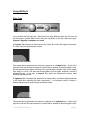
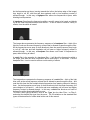
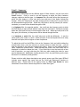
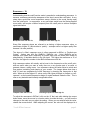
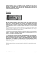
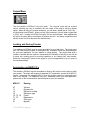
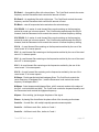
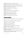
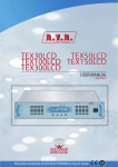
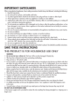
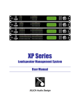
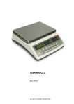
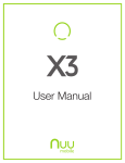
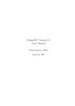
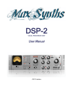
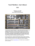
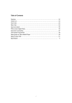
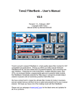
Tone2 BiFilter2 – User’s Manual
Revision 1.0 – January, 2007
BiFiliter2 written by Markus Feil
Manual written by Michael McGrath and Markus Feil
Copyright 2005 Tone2.
visit us at www.tone2.com
Tone2 BiFilter2 manual
page 1
Tone2 is proud to present BiFilter2, a high-end quality stereo filter module for VST/AU
compatible host applications. BiFIlter2 2 drastically extends the ‘filter plug-in’ concept to
provide today’s creative musicians with an extremely powerful multi-effect tool.
We have worked hard to create the ultimate filter module for today’s musicians, and are
certain that you will find it to be a useful and powerful tool in your musical arsenal. We
hope you have a lot of fun making music with BiFilter2!
Please visit our webpage at www.tone2.com for the latest news and updates for all of
our products.
Specifications
VST/AU compatible effect plug-in
Windows 9x/XP, MAC OS X
Intel, AMD or 68xxx CPU
Sample rates: 22, 44, 48 or 96 kHz
Frequency response: < 20hz to > 20,000hz
Stereo sound
Dual multi-mode filters with 47 filter types
8 distortion Types
8x oversampling
MIDI-support
Dry/wet mixing
High performance/low CPU
Installation Notes
To install the plugin, simply run the setup EXE file. You will be prompted to select the
install folder – please make sure that you choose the location that your VST host
application uses as the default ‘VSTPlugins’ folder. When the installation is completed,
BiFilter2 will be available on the effect plug-in menu of your VST host application. An
uninstaller will be created and added to your start menu, which you may use if you would
like to remove the plugin from your computer at a later time.
Tone2 BiFilter2 manual
page 2
Using BiFilter2
Filter Type
Let’s consider the filter type first. While there are many different types (the 47 ones will
be discussed in greater detail below) most are variations on the four main filter types,
lowpass, highpass, bandpass and notch.
A lowpass filter allows low frequencies to be heard, but blocks the higher frequencies.
It is often used for isolating bass sounds.
Lowpass Filter Response
The image above represents the frequency response of a lowpass filter – think of the
light blue color as the sound frequency content that is allowed to pass through the filter.
As the frequencies get higher (moving to the right along the bottom edge of the image)
they begin to ‘roll off’, with less and less emphasis until no higher frequency content is
allowed through. In this way, a lowpass filter allows low frequencies to pass, while
blocking high frequencies.
A highpass filter is basically the opposite of a lowpass filter, and allows high frequencies
to be heard while blocking the lower frequencies. It is frequently used to create hipitched whistle sounds, and piercing synthesizer leads.
Highpass Filter Response
The image above represents the frequency response of a highpass filter – think of the
light blue color as the sound frequency content that is allowed to pass through the filter.
Tone2 BiFilter2 manual
page 3
As the frequencies get lower (moving towards the left on the bottom edge of the image)
they begin to ‘roll off’, with less and less emphasis until no low frequency content is
allowed through. In this way, a highpass filter allows low frequencies to pass, while
blocking low frequencies.
A bandpass filter allows the frequencies within a specific range to be heard, and blocks
out all the other frequencies above and below it. It can be used to create a variety of
effects, from the subtle to insane!
Bandpass Filter Response
The image above represents the frequency response of a bandpass filter – think of the
light blue color as the sound frequency content that is allowed to pass through the filter.
As the frequencies move away (in both directions) from the center frequency they begin
to ‘roll off’, with less and less emphasis until no lower or higher frequency content is
allowed through. In this way, a bandpass filter allows a set ‘band’ of frequencies to
pass, while blocking all others.
A notch filter is the opposite of a bandpass filter – it will block the frequencies within a
set range, and allow all other frequencies above and below it to be heard. Like the
bandpass filter, it can be used to achieve a wide variety of effects.
Notch Filter Response
The image above represents the frequency response of a notch filter – think of the light
blue color as the sound frequency content that is allowed to pass through the filter – and
note that this time the filter’s shape blocks frequencies from passing instead of allowing
them. As the frequencies move away (in both directions) from the center frequency, the
sound begins to ‘roll back in’ - with more and more emphasis until all lower and higher
frequency content is allowed through. In this way, a notch filter blocks a set ‘band’ of
frequencies, while allowing all others to pass.
To select a filter type on BiFilter2, click on the ‘Type’ box for either Filter 1 or Filter 2,
and select the desired filter type from the menu. The 53 variations on the standard filter
types will be described in further detail at the end of this manual.
Tone2 BiFilter2 manual
page 4
Cutoff – ‘frequency’
Now that we understand how the different types of filters function, we can look at the
Cutoff function. Cutoff is used to set the frequency at which the filter’s behavior
changes, relative to the filter type. In a lowpass filter, the cutoff will set the frequency at
which the filter begins to ‘close’ and allow less and less of the higher frequencies
through. When the frequencies are high enough past the cutoff point, no more sound
will be allowed through the filter. When the cutoff point is set fully closed (full counterclockwise), no sound will be allowed through the filter.
In a highpass filter, the opposite applies – the cutoff sets the frequency point at which
the filter begins to reject sounds that are lower than the cutoff point. Sounds far enough
below the cutoff point will not be let through the filter at all. When the cutoff point is set
fully open (full clockwise), all frequencies will be allowed through the filter.
In a bandpass or notch filter, the cutoff value acts a little but differently – it sets the
center point of the ‘band’ or ‘notch’, which will taper off as the frequencies move away
from the cutoff point, both in higher or lower frequencies.
To adjust the cutoff on the BiFilter, click on the ‘frequency’ dial, and while holding the
mouse button down, move the mouse in a circular motion to rotate the knob – you will
hear the changes to the audio as you adjust the setting. When you are satisfied with the
value, release the mouse button. While adjusting the control, the cutoff value will be
displayed in a label box below the knob. If you would like to turn the knob with a finer
level of precision, you may hold down the <Alt> key while rotating the knob for more
precise adjustments. Additionally, holding down the <Ctrl> key and clicking on the knob
will reset it to its default (center) position.
Please note that while these descriptions are generic across most filter types, BiFilter2
includes some ‘special’ filter types that use the Cutoff and Resonance functions in
different ways. Please refer to the section below on Filter Type Details for more
information on how these controls may differ for certain filter types.
Tone2 BiFilter2 manual
page 5
Resonance – ‘Q’
Understanding how the cutoff function works is essential to understanding resonance. In
essence, resonance controls the steepness of the ‘slope’ around the cutoff point. A very
steep slope would filter more frequencies sooner, relative to the sound moving away
from the cutoff point. In comparison, a very soft slope would have the filtering applied
more subtly, and require a farther frequency from the cutoff point to achieve complete
signal attenuation.
Bandpass Filter with low ‘Q’
Bandpass Filter with high ‘Q’
Steep filter response slopes are referred to as having a higher resonance value, or
sometimes a higher ‘Q’ (which refers to ‘quality’ – a steeper curve is a higher quality filter
because it is more precise).
The slope of a filter’s response curve is often measured in dB/Oct, or ‘Decibels per
Octave’. Values may look like 18dB/Oct, 30dB/Oct, etc. Using 18dB/Oct as an
example, this means that a frequency an octave away from the cutoff point would be
attenuated by 18 decibels relative to the full signal. The higher the resonance or ‘Q’ of
the filter, the higher the number in the dB/Oct measurement will be.
High resonance values will actually add a boost to the frequencies at the cutoff point,
and are useful when you want to really focus on a very precise part of a sound, or
generate intense, cutting tones. Low resonance values are better suited to subtle and
less precise ‘smoothing’ and shaping of your sounds. The images below show how a
high ‘Q’ level can emphasize the cutoff frequency by boosting the frequencies in that
area. When set to the highest ‘Q’ values, many filter types will begin to oscillate, or ‘selfresonate’, as the boosted frequencies begin to create feedback inside the filter. This is
often a very desirable and instantly recognizable effect.
Lowpass Filter with low ‘Q’
Boosting frequencies with high ‘Q’
To adjust the resonance in BiFilter2, click on the ‘Q’ dial, and while holding the mouse
button down, move the mouse in a circular motion to rotate the knob – you will hear the
changes to the audio as you adjust the setting. When you are satisfied with the value,
release the mouse button. While adjusting the control, the value will be displayed in a
Tone2 BiFilter2 manual
page 6
label box below the knob. If you would like to turn the knob with a finer level of
precision, you may hold down the <Alt> key while rotating the knob for more precise
adjustments. Additionally, holding down the <Ctrl> key and clicking on the knob will
reset it to its default (center) position.
Distortion
BiFilter2 includes a high quality distortion module, placed after the filter’s output in the
signal chain. Distortion effects are very commonly used alongside filters to add
beefiness or edge to the sound. BiFilter2 features 8 different distortion types (described
in more detail below), as well as the ability to bypass the distortion unit for ‘pure’ filtering
effects.
To use the distortion module, first select a distortion type by clicking on the display in the
‘Distortion’ section. This will bring up a menu of all available distortion types, and you
may select the desired distortion type from the list.
The Drive knob is used to adjust the amount of signal that is being fed into the distortion
module. The higher the value, the greater the effect of the distortion effect will be, from
subtle to very overdriven and extreme sounds.
To adjust the drive, click on the Drive dial, and while holding the mouse button down,
move the mouse in a circular motion to rotate the knob – you will hear the changes to
the audio as you adjust the setting. When you are satisfied with the value, release the
mouse button. If you would like to turn the knob with a finer level of precision, you may
hold down the <Alt> key while rotating the knob for more precise adjustments.
Additionally, holding down the <Ctrl> key and clicking on the knob will reset it to its
default (center) position.
With the pre/post knob you can select whether the distortotion is applied before or after
the filter.
Tone2 BiFilter2 manual
page 7
Output Mixer
The final module in BiFilter2 is the mix panel. The “dry/wet” knob acts as a blend
control, allowing the user to creatively mix the output of the plug-in with the original
signal. When set fully left (counter-clockwise), you will hear a signal that is 100% ‘dry’ –
no processing from BiFilter2. When set fully right (clockwise), you will hear a signal that
is 100% ‘wet’ – nothing but BiFIlter2’s output, and no original signal. Most applications
will call for a setting that is somewhere in between the two – as always, experiment and
set this control to a level that suits the desired result.
Loading and Saving Presets
Your settings on BiFilter2 may be saved and called up at a later time. The plugin uses
your VST host’s preset system to accomplish this, so please consult the documentation
for your host application for more details on using presets. The plugin ships with a
number of presets that are useful to demonstrate the flexibility of the plug-in, as well as
to serve as a starting point for musical inspiration or for creating your own presets.
Select the “load preset” option for the plugin in your host application to try out some of
the included settings.
Automation and MIDI CC’s
The controls in BiFilter2 may be automated to allow for full control over the plug-in within
your project. The plugin will respond to standard VST automation, as well as to MIDI CC
control. Information on mapping MIDI CC’s to the plugin's controls is presented at the
start of this manual. For details on using VST automation within your host application,
please refer to the documentation that accompanies your host software.
MIDI CC
Routing
07
11
12
13
70, 73, 74
71, 72
75
91
Volume
Dry/wet mix
Distortion routing
Distortion type
Cutoff
Resonance
Filter type
Bypass
Tone2 BiFilter2 manual
page 8
Filter Type Details
Below you will find a description of the different filter types found in BiFilter2:
Off – The filter is disabled.
LP 30dB – A lowpass filter with a 30dB/Octave slope.
LP 12dB – A lowpass filter with a 12dB/Octave slope.
LP Analog – A analogue modeled lowpass filter with self oscillation.
LP Moog – A lowpass filter with a 24dB/Octave slope, with a classic ‘Moog Diode
Ladder Filter’ type response.
LP Fat - A lowpass filter with very broad resonance.
LP Oct – A lowpass filter with resonance tuned in octave distance from the cutoff point.
LP Elliptic - A ‘brickwall like’ lowpass filter with very steep slope.
HP 30dB – A highpass filter with a 30dB/Octave slope.
HP 12dB – A highpass filter with a 12dB/Octave slope.
HP Elliptic - A ‘brickwall like’ highpass filter with very steep slope.
HP Analog – A analogue modeled highpass filter with self oscillation.
BP 15dB – A bandpass filter with a 15dB/Octave slope.
BP 6dB – A bandpass filter with a 6dB/Octave slope.
BP Analog – A analogue modeled bandpass filter with self oscillation.
BR – A band rejection or notch filter with an adjustable center frequency and slope.
BR Analog – A analogue modeled notch filter with self oscillation.
EQ Low Shelf – A lowpass shelving filter.
EQ Hi Shelf – A highpass shelving filter.
EQ loudness – A loudness filter. Frequency controls low boost, resonance control high
boost.
Tone2 BiFilter2 manual
page 9
EQ Peak 1 – An equalizing filter with a broad slope. The Cutoff knob controls the center
frequency and the Resonance knob controls the amount of boost.
EQ Peak 2 - An equalizing filter with a tight slope. The Cutoff knob controls the center
frequency and the Resonance knob controls the amount of boost.
EQ Block – cuts all frequnecies below and above the selected range.
VOC IEAOU 1 – A series of vocal formant filters, each centering on the frequencies
emitted by vowel use in human speech. The Cutoff knob morphs through the IEAOU
formants, and the Resonance knob controls the amount of formant frequency shifting.
VOC IEAOU 2 – A series of vocal formant filters, each centering on the frequencies
emitted by vowel use in human speech. The Cutoff knob morphs through the IEAOU
formants, and the Resonance knob controls the amount of formant frequency shifting.
VOC A - A vocal formant filter centering on the frequencies emitted by the use of the
vowel sound ‘A’ in human speech.
VOC - A vocal formant filter centering on the frequencies emitted by the use of the vowel
sound ‘U’ in human speech.
VOC - A vocal formant filter centering on the frequencies emitted by the use of the vowel
sound ‘E’ in human speech.
VOC I - A vocal formant filter centering on the frequencies emitted by the use of the
vowel sound ‘I’ in human speech.
VOC O - A vocal formant filter centering on the frequencies emitted by the use of the
vowel sound ‘O’ in human speech.
W-Shape - Double parallel-switched bandpass filters. The Cutoff knob controls the
center frequency of bandpass filter 1, and the Resonance knob controls the center
frequency of bandpass filter 2.
M-Shape - Serial lowpass and highpass filters, with 2 resonant maxima at the edges of
the filter - cuts both treble and bass. The Cutoff knob contols the lowpass frequency and
the Resonance knob controls the highpass frequency.
Allpass – Does nothing, just changes the phase of the signal.
Phaser - A phasing filter that affects the phase offset of the incoming audio stream.
Comb 2x – A comb filter, with multiple equally spaced resonance peaks.
Comb 3x – A different comb filter, similar to Comb 1.
Comb 5x – A different comb filter, similar to Comb 1.
Tone2 BiFilter2 manual
page 10
Resonator – An oscillator which is excited from the input signal.
Diffuser 8x– A 8 step diffuser filter with feedback. Sounds like small room reverb.
Diffuser 32x– A 32 step diffuser filter with feedback. Sounds like large room reverb.
Delay – Delays the input signal by a given ammount.
Resample – Resamples the signal to a lower samplerate.
AM - Amplitude modulatuion.
Formant 2 - Double Formant (vocal) filter with 2 resonant maxima.
FM Sine – Frequency modulation with a sine oscillator.
FM Tri – Frequency modulation with a triangle oscillator.
FM Saw – Frequency modulation with a saw oscillator.
FM Square – Frequency modulation with a square oscillator.
Distortion Type Details
Below you will find a description of the different distortion types found in the BiFilter2:
Off – When this mode is selected, the distortion module will be bypassed.
Volume – Drive controls the volume of the signal.
Tube Amp – A ‘soft knee’ saturated distortion.
Transistor – An asymetric 'soft knee' distortion.
Presence – A ‘soft knee’ saturated distortion with falloff at higher levels.
Hard Clip – A ‘hard knee’ clipping distortion.
Bitcrush – This distortion type reduces the bitrate of the audio to ‘lo-fi’.
Waveshape – This distortion type adds additional harmonics by using round nonlinear
amplification of the audio signal.
Pow2 – This distortion type adds additional harmonics by using edged nonlinear
amplification of the audio signal. It is similar to exciters.
Tone2 BiFilter2 manual
page 11