1
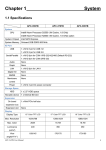
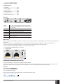
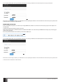
ESR100
ELDES DIGITAL RECEIVER
Contents
1. QUICK START GUIDE.................................................................................................................................................................3
2. RECOMMENDED NETWORK DIAGRAM.....................................................................................................................................5
3.TOOLBAR..................................................................................................................................................................................6
4.ADMIN.......................................................................................................................................................................................6
5. LOWER TOOLBAR......................................................................................................................................................................7
6.DEVICES....................................................................................................................................................................................8
7. CLIP DATA BASE......................................................................................................................................................................10
8.MONITORING.......................................................................................................................................................................... 11
9.GSM.........................................................................................................................................................................................12
10. RECEIVER................................................................................................................................................................................13
11. PASSWORD RESET..................................................................................................................................................................14
2
EN
User manual ESR100 v.1.1
1.QUICK START GUIDE
Package Content
1. ESR100....................................... qty. 1
2. Power supply.............................. qty. 1
3. User manual............................... qty. 1
4. Quick start guide....................... qty. 1
5. GSM antenna.............................. qty.1
6. Password reset token............... qty.1
Main unit
POWER
LED
POWER HDD
BUTTON LED
USB
ANT
COM
1
SIM CARD
SLOT
Power
button
Off – device is not powered up; Red – device is powered up and turned Off; Blue – device is powered up
and turned On.
Power LED
Off – device is turned off; Steady On – device is turned on.
HDD LED
Off – device is not active; Blinking several times per
second – device is currently active.
SIM Card Slot
Slot for the SIM card.
USB
USB to serial converters (USB 1... 4).
COM
Serial connection
ANT
GSM antenna connection
How to start
Before you begin using ESR100 you will have to preform certain system configurations, depending on your network topology or personal
preferences.
This can be done by connecting ESR100 to your local area network (LAN) or a personal computer and using an Internet browser.
For best security and user experience please use a modern web-browser like: Chrome, Firefox, Opera, IE9+.
There are 2 ways to make ESR100 available in your local area network (LAN):
1. Via ETH0 Fixed (192.168.1.10) Recommended
2. Via ETH1 DHCP
DHCP
ETH1
FIXED
ETH 0
DC IN
12V
2
CONNECTION VIA ETH0 FIXED (192.168.1.10)
Connect the ETH0 port to your personal computer via the LAN cable.
In order for the device to start working, you need to make sure that Your machine’s IP address is in the same subnet as the device’s IP
address. Also, please make sure that your machine’s netmask is the same as the device’s netmask (255.255.255.0).
Example:
Your IP address: 192.168.1.xxx
Device’s IP address: 192.168.1.10
xxx - any number besides 10.
Next, enter the I.P. address in the address bar of your browser and press enter:
3
User manual ESR100 v.1.1
EN
3
You should be redirected to the Login window, where you can enter your default user name and password , see picture below.
4
After the successful login procedure, you will be able to start operating the device. For more information and control options, please refer
to About section of the device web-interface.
CONNECTION VIA ETH1 DHCP
Connect the ETH1 port (see pic. 2) to the router, running a DHCP server, which in turn must be connected to your personal computer via
the LAN cable.
The device should automatically set up the connection
After connecting the cable, you will need to find out the device’s IP address. You can do that in your DHCP server settings or by contacting your
internet service provider.
Enter the specified I.P. address of the device in your browser’s address bar.
5
You should be redirected to the Login window, where you can enter your default user name and password , see picture below.
6
After the successful login procedure, you will be able to start operating the device. For more information and control options, please refer
to About section of the device web-interface.
4
EN
User manual ESR100 v.1.1
2.RECOMMENDED NETWORK DIAGRAM.
It is highly recommended to use the following ESR100 network connection diagram:
7
MS-1
RS232 NULL
Modem cable
(Included in package)
MS-2
RS232 to USB
converter
...
MS-5
ESR100
SERIAL
USB-1
ETH0
ETH1
Static
Dynamic
ROUTER
LAN
WAN
Internet
Provider
...
RS232 to USB
converter
USB-4
YOUR
PC
NOTE: MS - Monitoring Station, you can connect up to 5 monitoring stations.
ESR100 uses 3 ports:
• Http (80) – web interface
• Ssh (22) – remote updates
• Receiver (15000) – incoming data from wireless devices.
You need to set port forwarding in your Router for these ports.
For safety reasons, we recommend to set port forwarding only for receiver port (15000 by default) and access web interface only from
local network.
We do not recommend to connect ESR100 directly to WAN. However, this possibility is available.
In this case we recommend to turn off remote access on ETH0 or ETH1 (depending to witch WAN is connected) in web interface section
Receiver.
User manual ESR100 v.1.1
EN
5
3.TOOLBAR
8
Devices - opens the Devices section, where you can review information about wireless devices and adjust their settings.
Monitoring - opens the Monitoring station window, where you can manage monitoring station settings.
GSM - opens the GSM settings window, where you can view the modem status and change CSD settings.
Receiver - this section provides receiver control options and LAN configuration settings.
About - redirects to the help section, where you can download the user manual for current version.
NOTE: The upper toolbar is fixed at the top of the window and will appear in all sections
4.ADMIN
9
Admin - opens up the drop-down list, which allows you to logout or change admin credentials, like the username and password.
10
To change current login credentials you have to enter your current username and password in specified fields. Then you need to enter
your new username and password, and click Change button afterwards.
6
EN
User manual ESR100 v.1.1
5.LOWER TOOLBAR
The lower toolbar provides you with information about the modem and receiver status, as well as information about system load, memory
usage copyright information and the current version of the Web platform.
11
Modem - Shows the modem status.
Values:
• Online - shows the modem signal strength level
• Offline - no SIM card inserted or SIM card is not active.
When the modem is offline, a
icon will appear next to the modem status, indicating that the modem isn’t working. When you
mouseover the icon, you can view the notification, regarding the modem’s offline status.
When the modem starts up, the
icon will disappear.
12
Receiver - Shows the receiver status.
Values:
• Running
• Not running
System load % - Specifies how much system resources are currently used.
Memory usage % - Specifies current memory usage of the system.
NOTE: The lower toolbar is fixed at the bottom of the window and appears in all sections.
User manual ESR100 v.1.1
EN
7
6.DEVICES
Devices section displays information about wireless devices, which are currently being monitored.
13
Wireless devices which are not communicating with the receiver are highlighted in red.
Unit ID - Identification number of a certain wireless device.
14
NOTE: When you put your mouse over a certain unit ID, a box will pop up, indicating the IMEI number of the device.
ATTENTION: Unit and Account ID must be unique. If two units or accounts will have the same ID number, the device will not be able to
operate correctly. It is recommended that the account ID and Unit ID would be the same and unique.
Account - Identification number of the account, assigned to a wireless device, which is sent to the monitoring station during data
transmission.
Last Channel - Data transmission channel used to receive the last event.
Available channels:
• TCP
• UDP
• SMS
• CSD
Last Channel Value - Value, depending on the channel used to receive the last event.
15
If the Last Channel used for data transmission was TCP/UDP, the value will be will be specified as an IP address.
If the Last Channel used for data transmission was SMS/CSD, the value will be will be specified as a telephone number.
NOTE: If the CLIP DB parameter is turned ON and SMS/CSD channel is used for data transmission, the Last Channel Value field will
display a name assigned to the telephone number in CLIP DB database. For more information see chapter 6. CLIP DB.
FW Version – Current firmware version of connected devices.
GSM Level - GSM signal strength level.
8
EN
User manual ESR100 v.1.1
Updated - time of the last ping or any data received from a certain wireless device by the monitoring station.
16
NOTE: When you put your mouse over a certain event time, a box will pop up, indicating the date and time of the last Contact-ID event
received from the wireless device. This date and time is received from a wireless device.
Timeout 1... 3 - If there were no messages from the device during the set time value in the Timeout 1,2 and 3 a notification is sent to the
monitoring station after each timeout.
All timeout values are indicated in minutes. You can see that, when you put your mouse over any of the Timeout headline. If one of the
Timeout values i set to 0, the notifications will not be sent.
17
Monitoring station - Shows which monitoring station receives a certain event and what data transferring type was used.
There are 2 ways of connection. Directly via a serial port, or via one of the 4 available USB ports , using USB to Serial converter. Serial is
default port, so if USB1-4 is down it will send data through Serial port.
USB 3
18
USB 1
COM
USB 4
USB 2
SERIAL
Serial port pin definitions
19
Serial - Serial port
USB1 - USB port
USB2 - USB port
USB3 - USB port
USB4 - USB port
ATTENTION: If you want ESR100 to display event times correctly, you must set the Time Settings. The time settings can be found in
Receiver menu.
Delete button
20
You can delete a certain device from the database by clicking the Delete button next to it. After the button is pressed, a message will pop
up, asking you to confirm your action.
User manual ESR100 v.1.1
EN
9
7.CLIP DATA BASE
ATTENTION: Numbers which are NOT added to the CLIP Data Base will NOT be able to communicate with the monitoring station.
21
CLIP Data Base section allows you to turn on CLIP Data Base function. When it is turned on, the system will receive incoming alerts and
event notifications Only from the numbers located in the list.
Each time CLIP Data Base function is turned ON or OFF a verification window pops up, asking you to confirm your actions.
Add New Number - Allows to add a new number to the CLIP Data Base section. Pushing this button takes you to a number adding
section, where you have to enter your number and name.
22
After entering the required information in the appropriate fields, click the Add button.
23
Numbers:
Name - name of a user in the database.
Number - telephone number of the user in the database.
Updated - last time the user information was added or updated.
Additional options:
There are three buttons next to each entry in the database.
24
1
2
3
1. View button - show more detailed information about the certain user.
2. Edit button - change information of an existing user.
2. Delete button - delete existing user from the database.
25
If the CLIP Data Base parameter is turned ON and SMS/CSD channel is used for data transmission, the DEVICES → Last Channel Value
field will display a username assigned to the telephone number in CLIP Data Base.
10
EN
User manual ESR100 v.1.1
8.MONITORING
Monitoring section provides access to monitoring station settings.
26
Name - name of the channel, receiving data from the monitoring station.
Baudrate - speed of COM port settings.
Heartbeat - function, allowing to check the signal between the monitoring station and the receiver.
Heartbeat Period (s.) - pauses between signal checks in seconds.
Receiver No - receiver number (0 - 9).
Line No - line number (0 - 9).
27
ATTENTION: Minimum value of the Heartbeat Period is 30 seconds. The system will not allow to enter a lower value then 30 seconds.
Editing monitoring station parameters
28
Parameters, which have been edited have a green outline around them.
In order to save edited options, you must click the check-box, located at the end of each entry in the table.
29
After you click the check-box, the Submit Selected button will be highlighted and you will be able to save you parameters.
30
User manual ESR100 v.1.1
EN
11
9.GSM
GSM section lets you check the modem status and configure CSD parameters.
In order to use the GSM section, you will need to insert a SIM card with disabled PIN code request into ESR100.
You can disable the PIN code by placing the SIM card in your mobile phone and following the appropriate menus on your mobile phone.
For maximum system reliability we recommend you NOT to use a Pay As You Go SIM card. Otherwise, in the event of insufficient credit
balance on the SIM card, the system would fail to function correctly.
We also recommend you to disable call forwarding, voice mail/text message reports on missed/ busy calls. Please contact your GSM
provider for more details on these services and how to disable them.
31
The modem status window show different information about the modem.
Status - modem status, online/offline.
Signal level - current modem signal level.
Operator - current GSM operator.
Country - the country of the current GSM operator.
IMEI - IMEI number of the modem.
Last update - time of last update of the modem status information.
CSD settings are used to set up parameters for transferring data through CSD.
30
Connect Time - A period of time intended for the device to call the receiver, connect and start exchanging data.
Session Time - A period of time, intended for data transferring. After the receiver receives a call from a wireless device and successfully
establishes connection, it starts transferring data. The data transfer ends and the receiver hangs up after the set time in this field, even if
some of the data wasn’t successfully transferred.
Submit button - Saves changes to the CSD settings.
12
EN
User manual ESR100 v.1.1
10.RECEIVER
Settings section allows you to view receiver status and control options as well as configure LAN parameters.
32
Start button - activates the receiver (providing it was deactivated). Activates the receiver if it was previously turned off.
Restart button - restarts the receiver. Used to restart the receiver if malfunctions or problems are present.
Stop button - deactivates the receiver (providing it was activated). Used to deactivate the receiver when maintenance or device
relocation is required.
Status - show current receiver state, running/not running.
Version - specifies the version of the receiver.
refresh button - Refreshes the Status window, so the latest receiver status could be seen.
ATTENTION: If the receiver is turned Off, devices will NOT be able to communicate with the monitoring station by any channel (TCP;
UDP; SMS or CSD).
33
# - sequence number of receiver ports.
Name - names of receiver ports.
Remote access - This will disable remote access on eth0 or eth1 port through http(80) and ssh(22) ports. Remote access can be disabled
only on one port at a time (eth0 or eth1).
Type - network protocol type
• dhcp - dynamic host configuration protocol
• static - static network configuration protocol
Status - current status of the network, Online/Offline.
Mac - network address of a certain port.
IP - IP address of a certain port.
Netmask - subnet mask of you IP address.
Gateway - your network gateway.
Submit button - saves the changes and reboots ESR100.
NOTE: If the network settings have been changed and the user does not log on within the next 15 minutes, the network settings will
revert to default state (see pic. 32).
TCP/UDP Port
TCP/UDP Port is used for exchanging data with security systems such as Eldes EPIR3 and ESIM364.
User manual ESR100 v.1.1
EN
13
34
Default value of TCP/UDP port is 15000.
Time Settings
In order for the monitoring station to display events and update information correctly, you must set the Time zone.
35
You can do that by clicking the arrow on the left of the timezone field, and selecting the timezone from the drop-down list. After you have
selected the time zone, press the Submit button.
The default Timezone value is UTC.
There is also an option to specify the NTP server for time synchronization. If ESR100 is used in closed local network and can’t access NTP
server, please specify your own local NTP server.
11.PASSWORD RESET
36
If you have forgotten your password, you can reset it. You can do it in the Password reset section, which accessible from the main login
screen through reset it button.
37
In the password reset screen, please enter the information from your password reset token, which is included in the package. After
entering the required information press the submit button. Your username and password will be restored to their default values.
If you don’t have the password reset token, please contact Eldes support and provide your device imei number. The imei number can be
located on the case of the device.
14
EN
User manual ESR100 v.1.1
User manual ESR100 v.1.1
EN
15
Made in the European Union
www.eldes.lt


![Vartotojo instrukcija [EN-LT]](http://vs1.manualzilla.com/store/data/005677878_1-a86a2af2e1ae82877aae962daf812c7c-150x150.png)