1
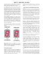
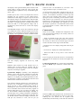
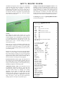
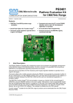
KIT 73. BIG PIC CLOCK
This project was originally published in the Australian
electronics magazine, Silicon Chip, 3/2001. It is issued
here as a kit with permission. Some modifications to
the original published circuit and software have been
made and are are mentioned at the end of the
documentation.
The Big PIC Clock is based on a PIC16F84
microcontroller (uC.) The software in the uC allows for
very accurate timekeeping. For visibility at a distance it
uses 2.3”/57mm super large, hi-efficiency red LED
displays for the hours and minutes and smaller 0.56”
LED displays for the seconds. The circuit incorporates
a dimming feature so that at night the reduced ambient
light is sensed and the display is dimmed. Before we
construct the clock please read through the following
theory about clock adjustment and setting and the
general circuit description.
Accuracy Theory and Adjustment. The clock may be
adjusted for very good long-term accuracy. All crystalbased clocks have a tendency to run fast or slow. Some
use a trimmer on the crystal for adjustment but they
will still drift due to temperature changes over time.
However, in this design an accurate adjustment feature
has been built into the software. Carefully adjusted you
should be able to get the clock to keep time to within a
few seconds a year. The adjustment technique requires
you to correctly set the clock and wait a few days to
see how accurate it is. Then an adjustment mode is
selected and the number of seconds the clock differs
from the correct time calculated over a period of 60
days is entered in.
However, it is not necessary to wait 60 days. In the
beginning a day or so is long enough to get a good idea
how fast or slow the clock is running. The only
requirement is that you calculate the number of
seconds it would gain or lose in 60 days. Of course the
more days you wait the greater the accuracy of the
adjustment
After entering the adjustment figure the clock then
maintains time by slightly adjusting the length of a
second every so often. If the crystal was running slow
then there will be an occasional shorter second
(999msec) to speed up the clock. Conversely, if the
clock was running fast there will be an occasional
longer second (1.001 sec) to slow it down.
In software the adjustment figure of seconds per 60
days is divided by 10,368 to obtain a reference counter
value. For example, if the adjustment figure is 60 (1
second per day) then the reference value will be
10,368/60 or 172. This value is compared with a
second counter which is increased once every
500msec. When the second counter value reaches the
value of the reference counter, the second counter is
altered by 1msec. The second counter is then reset to
count up again.
For our example value, the second counter will reach
172 after 500 x 172msec, or 86,400msec. Therefore, a
correction of 1msec is made every 86,400 msec which
is equal to 1 second per day. Thus there will be 1000
corrections per day. (One day has 86,400 seconds.)
The number of seconds per 60 days adjustment figure
requires a positive or negative sign to indicate whether
the clock needs to use slow seconds or long seconds. A
minus means the clock is slow and needs speeding up.
A plus (no sign) means the clock is fast and will need
to be slowed. The adjustment range is from 0 to –255
and from 0 to 255 seconds per 60 days with 1 second
per 60 days resolution. This corresponds to 0ppm
through to +/-50ppm adjustment with just under
0.2ppm steps.
The time adjustment is initiated by pressing both the
hatkey switches (one is for hour adjustment and the
other for minutes) simultaneously. The seconds display
will show an ‘Ad’. Upon release the current adjustment
figure will be shown. You can increase it by pressing
the hour switch and decrease it by pressing the minute
switch. If the number goes below zero the minus sign
will appear and these negative numbers are used when
the clock is running slow. The positive numbers are for
fast clocks.
Press both switches simultaneously to return to the
clock. The time will need to be reset correctly. The
adjustment number is stored in memory and will be
retained unless changed by entering the ‘Ad’ mode
again and changing.
Example: if you find the clock is 1 second fast every
60 days you need to add +1 to the current adjustment
figure. Thus if the current adjustment figure is –
35sec/60 day correction then it must be changed to –
34. Or if the current value was 38 then it must be
increased to 39.
Clock Setting. Use the minutes switch to go to the
correct hour and minute with the seconds at ‘00’ You
just wait until a reference clock (TV, radio) begins the
next minute. Pressing the minute switch will go to the
next minute, reset the seconds to ‘00’ and thus enable
the clock to be set accurately to about 1/10th second.
Daylight Saving. This is easy to do and nondisruptive. To advance the clock just press the hour
switch once. To retard the clock one hour just press it
23 times. That is, keep it depressed until the previous
hour comes up. In both cases the minutes and seconds
are unaffected.
12 or 24 Hour Display. You may toggle between each
display mode by depressing the hour switch when you
apply power. In 12 hour mode am or pm (your
decision) is indicated by the decimal point LED of the
leftmost display coming on. On initial power-up the
clock is in 24 hour mode.
Dimming. This is under software control. The duty
cycle for the multiplexed signals to all 6 displays is
varied. In a multiplexed display only one digit is on at
any one time but the displays are cycled on/off at such
KIT 73. BIG PIC CLOCK
a rapid rate that there is no noticeable flicker. When the
displays are driven at full brightness each display is on
for 1/6th of the time (the duty cycle is 16.6%.)
Software. Both the commented source code and the
object code are available for download from our
website.
The dimming feature uses a 1.5nF capacitor and a
Light Dependent Reststor (LDR.) The capacitor is
discharged each time a digit is about to be lit and the
PIC waits until the capacitor is charged before lighting
the display. In bright light the resistance of the LDR is
low so the capacitor charges up quickly and the display
is lit fast. In darkness or low light the LDR has a much
higher resistance, and the capacitor takes longer to
charge so the duty cycle for each digit is reduced. That
is the display is dimmed. The displays are dimmed
only in clock mode.
http://kitsrus.com/soft.html/clocksrus.zip
Power and Battery Backup. Use a 12VDC plugpack
for normal operation. Space has been provided for 4 x
AA NiCd or NiMH cells with solder tags. We have
NOT provided these since we think most people will
want to operate the clock with a plugpack. Also
batteries are heavy and add to the kit cost when buyers
may not want them. The metal pins to attach the
batteries to are provided.
With the batteries present when there is a power failure
the seconds hands keeps counting but not the large
displays.
Hardware. The interface circuit is complicated by the
fact that the PIC requires 5V while the large displays
require 12V. These requirements are catered for by
connecting the Vdd terminal of IC1 (pin 14) to the
+12V rail and the Vss terminal (pin 5) to a +7V rail
derived from a negative 3-terminal 5V regulator. IC2
(4051) then acts as a level translator (voltage shifter)
for the outputs of IC1 so that they can drive IC3
(ULN2003A) and the large displays.
Power from the 12V plugpack is applied to the circuit
via a 2R2 resistor and diode D1 which provides
polarity protection. The 2R2 resistor limits the current
into the zener diode should the voltage go above 15V.
REG1 is a negative 5V regulator. Diode D2 in the
GND leg sets the output at about –5.6V below the 12V
rail but this extra 0.6V is lost at diode D3 which feeds
pin 5 of IC1. The 100uF and 10uF capacitors decouple
the inputs and outputs of REG1.
The reason for increasing the output of REG1 to 5.6V
is to give a slightly higher ‘charged voltage’ for the
backup batteries which are charged via the 10R
resistor. D3 is included to reduce the supply to IC1
down to 5V. D4 is included to bypass the 10R resistor
when the circuit is powered from the batteries. This
lowers the impedence of the battery supply which is
desirable when driving a multiplexed display,
otherwise voltage variations to IC1 could cause false
resetting.
Note that there is a link LK1 between the batteries to
allow the backup supply to be disconnected.
IC1 operates at 4MHz as set by crystal X1. The 27pF
capacitors provide loading for the crystal so it will
oscillate within tolerance. These capacitors are
Negative Positive Zero (NPO) types which mean that
their temperature coefficient is zero and that they do
not alter their capacitance with normal temperature
variations.
Circuit Description.
Traditionally, clocks have always used crystals which
oscillated at a frequency which was a power of 2,
making it easier to divide the frequency down to 1 Hz
using bunary counters. The most common value of a
crystal used in this way is 32.768kHz. Others are
3.2768MHz amd 4.096MHz which need to be divided
by 100 and 1000 resp. first before division by powers
of 2.
Software is the key to the circuit. The hardware is
really just a collection of interface chips, displays and
components to input and output results into and out of
software to and from the real world. A look at the
schematic brings this point home clearly. Some
familiarity with the PIC16F84 uC is assumed.
In this kit, however, we have used a standard 4.0MHz
crystal because beside being readily available the need
to divide by powers of 2 is unnecessary when using a
uC to provide the clock function. We divide the 4MHz
by 16 then by 250 to obtain a 1kHz signal to multiplex
LED Pinouts. Pinouts are different for the two
displays. See the top overlay of K73A for the pinout
details of each display. Note that two of the large 2.3”
displays are mounted upside down.
KIT 73. BIG PIC CLOCK
the displays. This again divided by 500 to obtain a 2Hz
signal which is used to flash the colon on/off. The
seconds display is updated on every second 2Hz signal,
that is, 1Hz.
The RA4 pin on IC1 is set as an output and is used to
discharge the 1n5 capacitor via the 470R resistor.
When RA4 is taken high, its output is open-circuit and
the capacitor charges via the 2K2 resistor and the LDR.
As mentioned above the capacitor charges faster when
the LDR is in bright light (low resistance) and slower
when the LDR is in dull light.The charge time is
monitored by RA4 and used to control the display
dimming.
The RB0-RB7 outputs of IC1 drive transistors Q1-Q8
via a 470R base resistor. When the outputs are low, the
transistors are switched on to drive the segments in the
six displays. The segmenta are driven via 82R resistors
connects to the –5V from REG1 (ie, 5V below +12V
supply) and the Vee pin (7) connects to 0V.
As well as acting as the B & C outputs to IC2, pins 17
& 18 of IC1 are monitored via diodes D5 & D6 which
connect to the Minutes and Hours switches resp.The
other side of the switches both connect to the RA3
input (pin 2) of IC1. Normally, pin 2 is held low via the
10K resistor to pin 5. However, if a switch is pressed
and the B or C line driving the switch is high, the RA3
input will also be pulled high. This signals to IC1 that
the switch is pressed. IC1 can determine which switch
is pressed because it ‘knows’ which line (B or C) is
high at the time.
Construction
There are two PCBs. Assemble the components onto
each circuit board according to the overlay. There are
several points to note:
- Links. On K73B use the four zero ohm resistors
provided. There are 4 on K73B, not three as I wrote on
the overlay! On K73A use the tinned copper wire and
cutoff’s from the resistor legs to make the links.
- mount the two 0.56” displays using half of the 20 pin
IC socket.
- two of the 2.3” displays are mounted upside down.
- mount the LDR so its top face is level with the
displays.
while the decimal points are driven via a 180R resistor.
The 0.56” display segments are driven by 220R
resistors.
Different feed resistors are used because the 2.3”
displays have 4 series LEDs per segment and two
series LEDs in the decimal points. The 0.56” displays
only have one LED per segment.
If you are going to mount the Clock in a case decide if
you want the two switches S1 and S2 to be higher than
they are.
Connecting the Boards. X1, X2 and X3 on K73B take
the three female 8-pin connectors. Solder them into
place.
Upside-down Displays. Normally with multiplexed
displays such as this the same segments for each digit
are connected in parallel. This circuit, however, is
different. Two displays are mounted upside down. This
has been done to obtain a colon between the hours and
minutes and to obtain the am indicator.
The common cathode connections to each display are
driven by IC3, a ULN2003A 7-transistor array. IC3 is
driven via IC2, a 4051 8-channel analog switch or
demultiplexer. In this circuit it has two roles. Firstly, it
acts as a decoder which converts the binary signals on
its three input lines (A, B, C) to drive six outputs, one
for each common cathode LED display. Secondly, it
provides logic level (voltage) translation, changing the
5V signals on its inputs to 12Vsignals to drive IC3. IC2
can do this because it has three supply connections: the
Vdd pin (16) connects to +12V, the Vss pin (8)
The three, male 8-pin connectors X4, X5 and X6 are to
be soldered on the underside of K73A so that, after
soldering the two boards will fit together both
mechanically and electrically. Note that the connectors
KIT 73. BIG PIC CLOCK
do NOT fit through the holes of X4, X5 or X6 drilled
in K73A PCB. The holes are meant as a placement
guide for soldering each connector. If you are
assemblying the kit alone use a piece of sticky tape to
hold the male connector vertical while the short pins
are seated in the holes. Just solder one pad and check
the connector is vertical. Make any correction needed.
Then solder the other pads.
Changes in this Kit from Original Version. In the
hardware we have not allowed for two types of 2.3”
LED display pinout. We have used the pinout our LED
supplier makes for us (which is the variant pinout of
the article.) Connecting the two boards together has
been improved. In software, the author John Clarke
kindly corrected a rollover fault so that 23:59:59 went
to 0:00:00. 12 hour mode is the default start-up mode.
Contacting Us. Email me at [email protected] if
you have any questions.
COMPONENTS
Tinned copper wire
Testing.
First check the bottom PCB, K73B just by itself
unconnected to K73A. Do not put in IC’s. Plug in
12VDC plugpack. Use a multimeter to check that there
is +5V between both pins 4 & 14 and pin 5 of IC1. For
IC2 there should be 5V between pins 16 & 8 and
between pins 16 & 7. If these reading are correct,
disconnect the power,
Insert the ICs correctly orientated. Connect the two
boards together. Apply power. The display should light
up and show 12:00:00. The display is in 12-hour mode.
To select the 24-hour display press the hour switch as
you connect power.
Push the two switches to see how the hour and minutes
increase. Cover the LDR to test the dimming feature.
Press both switches to check you can access the adjust
mode. If you bought 4 batteries for battery backup (not
supplied with the kit) then connect the LK1 link to
allow the batteries to charge from the plugpack.
If it does not work. Solder bridges and components in
the wrong way are the most likely problems. Did you
put in all the links? If one or more display segments are
wrong trace back the display to the components driving
that display segment. Look for dry-joints.
Adjustment outside +/-255. If you find that you need
an adjustment outside the range of +/-255 then this
means that the crystal is out of specification. This can
be fixed within limits by changing the loading
capacitors. If the clock is running fast and the
adjustment value needs to be more than 255 then
increase the 27pF capacitors to 33pF (NPO type.) If it
is running slow and needs an adjustment to be more
than –255 (that is, -256, -260 etc) then decrease the
loading capacitors to 22pF or 18pF (NPO type.)
Resistors 5%, 1/4W:
10R
R3
82R
R11 12 14 15 16 17 18
180R
R11
220R
R9 10 19 20 21 22 23
470R
R5 24 25 26 27 28 29 30 31
1K
R7
2K2
R2
4K7
R4
10K
R6
470K
R8
Zero ohm resistors for links on K73b
2R2 1W R1
0.1 104 box poly MKT
C10
1n5 box poly MKT
C9
1N4004
D1 2 3 4
1N4148
D5 D6
4.000MHZ
Xtal
10uF/25V mini
C1 2 3 4 6
100uF/16V mini
C5
15V 1W zener diode
ZD1
27p ceramic NPO type C7 C8
LDR
LDR
BC328
Q1 – Q8
4051
IC2
PIC16F84
IC1
ULN2003A
IC3
7905
IC4
20 pin IC socket
18 pin IC socket
16 pin IC socket
0.05” Metal Pins
3mm x 6mm nut and bolt set
Metal spacer 3mm x 15mm
3mm screws x 6mm
2 pin SIL header
jumper
LED 0.56" display
LED 2.3" display
8 pin female header
8 pin male SIL strip
K73A PCB
K73B PCB
12"
1
7
1
7
9
1
1
1
1
1
4
1
1
1
4
2
1
5
1
1
2
1
8
1
1
1
1
1
1
2
8
1 set
4
8
1
1
2
4
3
3
1
1