1
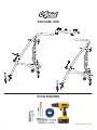
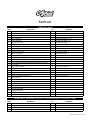
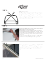
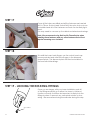
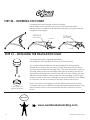
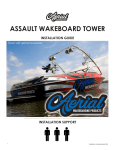
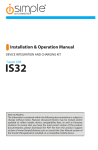
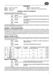
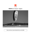
assault WAKEBOARD tower
installation guide
INSTALLATION SUPPORT
1
GUIDE#: pwb-ASSAULT-004
important information
• This Aerial wakeboard tower fits motor boats with 76-108 inch wide beam widths. This measurement is taken from the Port to Starboard mounting points.
• Do not fold the tower without having the top section securely fastened to the side sections with
the fasteners provided.
• Lubricate the telescopic side section tubes that slide in and out of the top section during installation. We recommend using a light grease to help the tubes slide together without binding.
• Do not fold the tower by yourself.
• Do not assemble tower on the ground and then try to install it on the boat.
• Do not use impact drivers to install any hardware.
• Torque set screws to 35ft-lbs
• Torque shoulder bolts 50 ft-lbs
• Torque tower foot all-thread to 65 ft-lbs
• We recommend using red Loctite threadlocker on the threads of all fasteners that will not be
adjusted while lowering or raising the tower.
• Check the top section for burr’s before installing side sections to prevent the scratching and
marking of tubes. Aerial does not cover damage caused by burr’s during installation.
• If the area of the deck where the tower will be mounted has a fiberglass thickness of less than
¼ inch, a backing plate kit must be purchased and installed to provide adequate support.
• Please leave the foam wrap on the tower until the installing is complete.
• Please note that when towing your boat you may notice what appears to be movement in
your tower. It is important to understand that the boat is also moving on the trailer and that this
movement can be visually deceiving.
cleaning
• Frequently wash your tower with soap and water.
• As required, use Mothers Mag & Aluminum polish to restore your tower to its original finish.
warning
• BE CAREFUL when assembling this product. We CANNOT be liable for any burring or scratching that may occur when sliding sections in and out of each other.
• NEVER modify this product in any way.
• NEVER climb, stand or ride on this product.
• NEVER tow watersport tubes or inflatable’s with this or any other Aerial Wakeboard Tower.
• ALWAYS use caution with approaching bridges or overpasses.
• ALWAYS inspect this product for loose bolts, fittings or damage before each use.
• Always carefully CONSULT the user manual for proper installation, maintenance and usage.
• Aerial is not liable for personal injury or property damage from the use of this or any other
Aerial product.
2
GUIDE#: pwb-ASSAULT-004
EXPLODED VIEW
TOOLS REQUIRED
3
GUIDE#: pwb-ASSAULT-004
PARTS LIST
TOWER PACKAGE
ITEM #
DESCRIPTION
QTY
COMMENTS
1
2.25" TOWER JOINT - THREADED (INCL. M6 X 12mm BOLT)
4
2
2.25" TOWER JOINT - THRU HOLE (INCL. M6 X 12mm BOLT)
4
3
DECK MOUNT
4
4
M12 X 40mm BOLT
12
FOR USE WITH ITEMS - 1, 2, 15
5
M12 X 45mm BOLT
8
FOR USE WITH ITEMS - 3, 30
6
M12 X & 75mm BOLT
4
FOR USE WITH ITEMS - 3
7
M12 SPRING LOCK WASHER
24
FOR USE WITH ITEMS - 4, 5, 6
8
M10 X 75mm BUTTON HEAD BOLT
4
FOR USE WITH ITEMS - 27
9
M10 NYLON LOCK NUT
4
FOR USE WITH ITEMS - 8
10
M12 NYLON LOCK NUT
4
FOR USE WITH ITEMS - 6
11
M12 FLAT WASHER
4
FOR USE WITH ITEMS - 6
12
LARGE FLAT WASHER (OD = 70mm)
4
FOR USE WITH ITEMS - 3
13
CURVED RUBBER WASHER (OD = 70mm)
4
FOR USE WITH ITEMS - 3
14
BIG FLAT WASHER (OD = 70mm)
4
FOR USE WITH ITEMS - 3
15
FRONT HINGE (TWO PARTS CONNECTED BY M12 X 40mm BOLT)
2
16
2.5" CLAMP
2
17
2.25" RUBBER COLLAR
2
FOR USE WITH ITEMS - 16
18
2.375" RUBBER COLLAR
2
FOR USE WITH ITEMS - 16
19
CLAMP JOINT WITH SLANT (INCL. M6 X 12mm BOLT)
2
20
M10 X 25mm BOLT
2
FOR USE WITH ITEMS - 19
21
LARGE WASHER FOR SIDE BLADE
4
FOR USE WITH ITEMS - 30
22
M12 ALLEN KEY
1
23
M10 ALLEN KEY
1
24
M8 ALLEN KEY
1
25
M6 ALLEN KEY
1
26
THREADLOCKER
1
27
TOP SECTION TUBE
1
28
LOWER SIDE RAILS
2
29
FRONT LEGS
2
30
SIDE BLADES
2
1 PORT & 1 STARBOARD
BOARD RACK PACKAGE - PER PACKAGE - 2 PACKAGES ARE GENERALY INSTALLED PER TOWER.
ITEM #
4
DESCRIPTION
QTY
COMMENTS
1
FORKS
2
2
LOGO PLATE WITH BUNGEE CORD
1
3
M6 X 20mm BOLT
4
FOR USE WITH ITEMS - 1, 2
4
M8 X 16mm BOLT
4
USED TO ATTACH RACK ASSEMBLY TO TOWER
GUIDE#: pwb-ASSAULT-004
step 1
The mounting feet will need to be assembled to the side
rail fittings, followed by attaching them to the side rails.
m12 split
lock washers
m12 x 45mm
lower side rail
fitting
m12 x 40mm
mount
step 2
Tape off all the areas that may potentially come into contact with the side rails.
step 3
Once the feet are connected to the side rails, hold the
side rail up to your boat. Once the rail is aligned with your
windshield use a small piece of tape to mark the position of
the mounting feet.
5
GUIDE#: pwb-ASSAULT-004
step 4
Once the desired position is achieved, place one of the
nylon mount washers over the piece of tape and trace
around it with a permanent marker.
step 5
Transferring marks from the other side.
This step is very important! After taping the second side of
the boat in approximately the same areas as the first side
you will need to measure the distance that you marked on
the first side of the boat
step 2
It is best to take measurements from the back of the boat
and mark with blue tape. Be sure to measure from the
same point on both sides.
6
GUIDE#: pwb-ASSAULT-004
step 6
Drilling
Once you have marked your 4 holes, check the
underside of the deck for wires.
If necessary, you should move the wires out of
the way while you drill. We recommend drilling a small pilot
hole which will keep the 17/32” drill bit from walking (moving). A small rat tail file can be used to ease the edge and
keep the gel coat from chipping.
Be careful of wires!
step 2
A
SMALL
DAIMETER
PILOT HOLE
B
17/32” DRILL BIT
C
COUNTERSINK
(THROUGH GELCOAT)
Gelcoat
Fibreglass
7
GUIDE#: pwb-ASSAULT-004
step 7
Install the tower mounts to the boat deck in the order shown in the diagram.
Note: in the case where the deck of your boat is less than 1/4” thick, a reinforcing kit
is required to thicken and reinforce the deck in the mounting locations.
CURVED DECK - MOUNT ASSEMBLY
FLAT DECK - MOUNT ASSEMBLY
M12 X 75MM
M12 X 75MM
BLACK NYLON WASHER
BLACK NYLON WASHER
MOUNT
MOUNT
NYLON WASHER
NYLON WASHER
CURVED RUBBER WASHER
FLAT DECK
CURVED DECK
REINFORCEMENT
REINFORCEMENT
RUBBER WASHER
RUBBER WASHER
ALUMINUM BACKING PLATE
SPLIT LOCK WASHER
NYLON LOCK NUT
ALUMINUM BACKING PLATE
SPLIT LOCK WASHER
NYLON LOCK NUT
step 8
Measuring from your windshield, check the distance to the
side rail to make sure both sides are symmetric.
8
GUIDE#: pwb-ASSAULT-004
step 8 - Continued...
The side rails need to be mounted straight up and down. If
they are leaning in or out, this will cause a problem with the
tower when you want to fold it.
step 9
split lock washer
m6 x 12MM
threaded lap joint
split lock washer
m12 x 40mm
m12 x 45mm
Assembling the Switch Blade (Rear Leg)
Start at the top of the switch blade and attach the trim
washer, shoulder bolt and threaded lap joint.
We recommend assemblying all the blade components
before installing the blade on the tower.
m12 x 40mm
split lock washer
threaded lap joint
m10 x 25mm
split lock washer
step 10
You will then need to attach the lower base to the threaded lap joint. This is then followed by attaching the clamp
to the lower base (using the stainless steel socket head cap
screw.)
9
GUIDE#: pwb-ASSAULT-004
step 11
The lower section of the switch blade can now be assembled to the
lower fittings and clamp using the trim washer, M12 X 45mm socket
head cap bolt and threaded lap joint.
step 12
Insert the front leg hinge joint into the lower section of the front arm
(repeat for the other side). Its important not to completely tighten
the fittings as some adjustment will necessary before the installation is
complete.
Before inserting the top-section, make sure there are no burrs in the
top-section. Someone will need to hold the top-section for you as you
insert the front arm into the top-section and fit the hinge into the side
rail.
*** IMPORTANT NOTES ***
- Lubricate telescopic parts with a light grease before sliding together.
- Grease will not prevent the smaller diameter tube from being
scratched by the top section tube during insertion so be very careful not insert the side section tube any further than the final installation
width.
Once the sides and top section are assembled the fittings that connect to the ends of the front legs can now be firmly tightened so that
they do not rotate.
step 13
The rear switch blades can now be installed by attaching the top switch
blade fitting to the fitting located on the upper section of the front leg. The
clamp located on the base of the switch blade will be connected to the
lower side rail. We recommend making sure that the clamps on both sides
of the tower are located the same distance from the end of the side rail so
that your tower looks symmetrical.
During the clamp installation, don’t forget to install the rubber clamp collar’s between the clamp and the lower side rail. These will be required to
allow the clamps to firmly fasten in place.
10
GUIDE#: pwb-ASSAULT-004
step 14
Drilling the top section.
The X measurement is a great way to make sure that your
tow point is in the center of your boat. To do this, measure
from the tow point to your rear foot, then to your other
foot. Cover your boat with an old sheet or old cover to
make removing the metal shavings easy. Someone should
hold the top section while you drill.
step 15
Using the pre-drilled holes in the top section tube, mark the
drilling positions on the front leg tubes.
Before making your marks, check to ensure that the tow
point is aligned correctly and positioned vertically. The tow
point should also be positioned on the rear of the top section tube so that the logo plate is facing towards the bow
of the boat.
We then recomend drilling the holes with a smaller drill bit
(smaller than the 27/64” drill bit) to make a pilot hole.
step 16
Following the pilot holes you just drilled, use a 27/64” drill bit
to create the clearance hole for the joining bolts.
As each hole is drilled we recommend inserting each bolt
so that it keeps the parts aligned while drilling the next
hole.
11
GUIDE#: pwb-ASSAULT-004
step 17
Once all the holes are drilled and all the fasteners are inserted
(M10 x 75mm - Button Head Socket Bolt) the nylon lock nuts can
be installed and all of the fasteners and nuts can be firmly tightened.
You may need to vacuum up the debris and aluminum shavings.
Note: We recommend using Red Loctite Threadlocker when
installing these fasteners and any other fasteners that will not
require loosening once installed.
step 18
To install the board rack fingers, use the socket head cap
screws provided and attach the fingers to the diamond
shaped plate. This diamond plate will then be installed to
the rear switch blade legs.
step 19 - locking the rotating fittings
Once you are happy with your tower installation and all
of the fittings are lined up to allow the tower to fold and
function correctly it will then be important to firmly lock the
fittings in place to prevent any unwanted rotation or loosening. We recommend using threadlocker during this step.
m6 x 12MM
12
GUIDE#: pwb-ASSAULT-004
step 20 - lowering the tower
Lowering the tower requires at least 2 people.
Never trailer your boat with the tower in the lowered position.
Always check to make sure all fasteners are tight and secure before
using the tower again.
OPTION A
DISCONNECT
OPTION B
loosen
DISCONNECT
loosen
step 21 - installing the navigation light
The navigation light is shipped separately.
It is designed to be installed on the top of the tow point.
For a clean wiring installation the wires supplied can be passed
through the center of the tow point, along the inside of the top-section and down inside the front leg tube. The wires will need to exit the
front leg tube just above the fittings and then be passed over the fittings before entering back into the side rail front tube. Finally the wires
will exit the side rail front tube just above the mounting foot and then
enter the deck of the boat (through a hole that will need to be drilled)
so that they can be connected to a switch and power source.
navigation light
(shipped separately)
Note: The tower is not supplied with pre-drilled wiring holes as each
customer may have a different wiring requirement depending on how
they fold their tower or the accessories that they will mount to the
tower.
Questions?
www.aerialwakeboarding.com
13
GUIDE#: pwb-ASSAULT-004