1
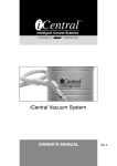
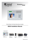
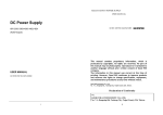
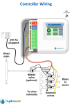
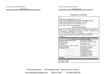
MINICOM Intercom System Installation & User’s Manual Rev 2 web: www.icentralsystems.com.au email: [email protected] Sales, Service, Spares consumer enquiries 1300 050 333 Minicom Installation & User’s Manual Rev 2 Document Part No. 890-434 iCentral Trade & Dealer Enquiries Head Office Ness Corporation Pty Ltd ABN 28 069 984 372 Ph +61 2 8825 9222 Fax +61 2 9674 2520 [email protected] Copyright Notice All rights reserved. No part of this publication may be reproduced, transmitted or stored in a retrieval system in any form or by any means, electronic, mechanical, photocopying, recording, or otherwise, without the prior written permission of Ness. Ness reserves the right to make changes to features and specifications at any time without prior notification in the interest of ongoing product development and improvement. © 2014 Ness Corporation ABN 28 069 984 372 CONTENTS INSTALLATION INSTRUCTIONS GENERAL INFORMATION.......................................................................... 2 LOCATION OF EQUIPMENT....................................................................... 3 WHERE TO RUN CABLE ............................................................................ 4 WHAT CABLE TO USE ............................................................................... 4 MAXIMUM LENGTH FOR CABLE RUNS ................................................... 5 INSTALLATION OF R70 ROOM STATIONS............................................... 6 INSTALLATION OF D70 DOOR STATIONS ............................................... 6 WIRING DIAGRAMS.................................................................................... 7 CABLE TERMINATIONS ............................................................................. 8 DOOR STATION ADJUSTMENTS .............................................................. 9 CHANGING THE CHIME ........................................................................... 10 CHIME (CH) OUTPUT................................................................................ 11 LOCK (LK) OUTPUT.................................................................................. 12 WIRING LOCK (LK) & CHIME (CH) OUTPUTS ........................................ 12 CABLE FUNCTIONS ................................................................................. 14 CABLE COLOUR CROSS REFERENCE .................................................. 14 USER INSTRUCTIONS INTRODUCTION ........................................................................................ 16 PARTS IDENTIFICATION.......................................................................... 17 CALLING ROOM STATIONS .................................................................... 18 CALLING DOOR STATIONS..................................................................... 18 ACTIVATING DOOR CHIME ..................................................................... 19 ACTIVATING LOCK OUTPUT................................................................... 19 ADJUSTING VOLUME CONTROLS.......................................................... 19 TROUBLE SHOOTING .............................................................................. 20 SPECIFICATIONS...................................................................................... 21 iCENTRAL MINICOM 1 INSTALLATION MANUAL GENERAL INFORMATION The following general procedures must be observed in relation to the location and installation of Minicom components: Stations are not to be installed “back to back” or in “line of sight” of each other as this will cause feed-back (squealing). Where stations are to be fitted externally, appropriate measures to provide weather protection are to be taken. Avoid running intercom cable parallel to electrical wiring. The plugpack should be located in an area with sufficient space to dissipate heat. Guidelines for maximum cable lengths as set out in this manual are to be observed to avoid the possibility of operating problems due to excessive voltage drop. The maximum number of Room and Door stations used in a system is generally limited to 4 in total. CAUTION: Failure to use specified cable may cause problems with the performance of the system. IMPORTANT: Responsibility will not be taken for problems that arise from the improper use of cable or interference generated externally to the system. Interference by light dimmers, fluorescent lighting and similar electrical products, must be corrected at the source. An aid to reducing the effects of this type of interference is to place stations and wiring no closer than 30cm (12”) from any AC device or wiring. The circuitry of the intercom has been designed to minimize the effects of Radio Frequency Interference however, total immunity to this type of interference cannot be guaranteed where the levels of interference generated are extreme. iCENTRAL MINICOM 2 INSTALLATION MANUAL LOCATION OF EQUIPMENT Careful consideration must be given to present and/or future layout of furniture so as not to locate stations in inappropriate positions. To avoid audio feedback, stations should be kept at least four to five metres away from other stations. Never have more than one station in any one room and avoid mounting stations in the same wall cavity i.e. directly below and above one another in a two storey house. A suitable height is generally 1400 millimetres from the floor to the centre of the unit. Stations located on timber frame walls should be located adjacent to a stud to allow firm fixing. Stations located on cavity brick walls will require the installation of wall boxes. Stations installed on single brick walls will require wall boxes and the cable will need to be run in conduit and chased into the brick wall. Where stations are required in bathrooms or laundries, they must be kept clear of water or steam. Where stations are mounted outside and are exposed to weather, the fitting of weatherproof covers is required. Stations must not be installed in saunas. Where Door Stations are to be installed in solid brick or concrete columns at a front gate, it is required that underground rated cable be used and run in conduit from the station to below ground level and back to the house. Suggested locations for the plug pack are kitchen cupboards, pantry, bedroom wardrobes etc. The plug pack is usually located no less than 1 metre and not more than 5 metres from the point of connection at a room station. It is an advantage to have the plugpack located so it can be easily turned off if required. iCENTRAL MINICOM 3 INSTALLATION MANUAL WHERE TO RUN CABLE Cables can be situated: In the roof space In false ceilings/bulkhead area Within internal and external walls Under floors (subject to access being available) Note: Intercom cables should be run as far away from AC wiring as practicality permits. Avoid running intercom cable parallel to any AC or other type of wiring. Running across at right angles is acceptable where necessary. Allow additional cable at each station for the purpose of termination. In the case of cavity brick walls, ensure the wires are pulled through one of the holes at the rear of the wall box. WHAT CABLE TO USE General Minicom requires cable with a minimum of 5 conductors (2 twisted pairs + 1 additional conductor) for operation. The system may be Star Wired from a central point or Loop Wired however the number of stations on a loop is governed by the length of the loop. See section “Maximum Length For Cable Runs”. Note: Different cables have different characteristics hence it is recommended that either ‘CAT5’ cable, ‘Telephone’ cable or ‘Valet’ cable, be used on all new installations. Many other cables will work acceptably however responsibility cannot be taken for problems that arise from the use of other cables. Where Valet cable is used, the shielded cores should be used for the Control (Con) terminals. Underground cable should be rated for underground use and run in conduit. Power Supply The Plug Pack supplied with the kit is fitted with a length of Figure 8 cable which should be of adequate length for most installations. Should this cable need to be extended, cut the existing cable about 30cm from the plug pack and join a piece of heavy duty figure 8 cable of required length. Ensure correct polarity (‘+’ & ‘-‘) is observed. iCENTRAL MINICOM 4 INSTALLATION MANUAL MAXIMUM LENGTH FOR CABLE RUNS The system may be Star Wired from a central point or Loop Wired however the number of stations on a loop is governed by the length of the loop and also the voltage output of the power supply used. The table below shows the relationship between the power supply used, length of a cable run and the number of stations permitted on the run. Note: The starting point to determine the length of a cable run is taken from the station where the plug pack is connected. CABLE RUN LENGTH V’s NUMBER OF STATIONS ON RUN Distance Using 13.8V Supply 200 metres 100 metres 65 metres 50 metres Distance Using 12V Supply 120 metres 60 metres 40 metres 30 metres No of Stations On Run One station on run Two stations on run Three stations on run Four stations on run Note: These maximum distances can be doubled where required by using spare conductors in the cable so that two conductors are used for POS and two conductors are used for NEG. It is vitally important that the number and type of conductors used for POS and for NEG are exactly the same. iCENTRAL MINICOM 5 INSTALLATION MANUAL INSTALLATION OF R70 ROOM STATIONS Room Stations in Timber Frame Walls Cut hole in wall lining keeping one side of the cutout adjacent to a stud so as to allow firm fixing. Fit room station housing into cutout and mark positions for wall fixing attachments. Remove housing and fit any required wall fixing attachments to the wall. Pull any cabling through the room station back housing and fit the back housing into the cutout and secure to the wall. Strip back the outer white covering of the cable (approximately 80 mm), then strip the individual wires (6 mm). Fix all wires into the appropriate screw terminals. (See diagram page 8) Screw metal chassis plate to back housing using 6 x small PT screws provided. Fit optional plastic trim (if applicable) around protruding part of back housing. Clip plastic front, over metal chassis plate, to back housing. Room Stations in Cavity Brick Walls Remove the brick and mortar and insert the metal wall box ensuring that all cables are first pulled through the holes in the rear of the wall box. Installation is then the same as for timber frame walls. INSTALLATION OF D70 DOOR STATIONS Depending on the type of wall to which the station is to be affixed i.e. timber or brick, installation is much the same as for room stations. Where stations are exposed to weather, a weatherproof cover should be fitted using silicone between the weather shield and the wall, sealing the top and side edges of the weather shield. iCENTRAL MINICOM 6 INSTALLATION MANUAL WIRING DIAGRAMS STAR WIRED ROOM STATION ROOM DOOR STATION STATION CHIME RELAY DOOR STRIKE RELAY ROOM STATION PLUG PACK SUPPLY INTERCOM CABLE FIGURE 8 CABLE OR LOOP WIRED DOOR STRIKE RELAY MECHANICAL CHIME RELAY ROOM ROOM ROOM DOOR STATION STATION STATION STATION INTERCOM CABLE PLUG FIGURE 8 CABLE PACK * Overall length of cable run is determined from the first room station to the door station. See section “Maximum Length For Cable Runs” iCENTRAL MINICOM 7 INSTALLATION MANUAL CABLE TERMINATIONS VR901 ROOM STATION CAT5 Cable BROWN BROWN / WHITE ORANGE BLUE BLUE / W HITE 105-422 POS NEG CON COM1 COM2 VR2 E1 D70 DOOR STATION 105-819 SEL PROG VR1 NOTE: Plug pack can be wired into “POS” & “NEG” at any station. See “Maximum Length For Cable Runs” in relation to Plug Pack location. iCENTRAL MINICOM 8 INSTALLATION MANUAL DOOR STATION ADJUSTMENTS There are 2 adjustments on the door station which may require fine tuning after installation. NOTE: A flat bladed screw driver with a blade width of between 2mm and 2.4m is required for these adjustments. The use of an incorrect screw driver may result in the pot being damaged. Speaker Volume Speaker volume at the door station is adjusted by means of a miniature trim pot (VR1). - See diagram below. Turning this pot will vary the speaker volume. This adjustment is best made while someone is communicating to the door station from one of the internal stations. Chime Volume The chime volume is adjusted by means of a miniature trim pot (VR2). - See diagram below. Turning this pot will vary the chime volume throughout the entire system. Before making an adjustment to this pot, adjust the slide volume control at each of the internal stations so that communication can be heard at an acceptable level. This door station pot (VR2) should then be adjusted so the chime comes through at an acceptable level, at the internal room stations. iCENTRAL MINICOM 9 INSTALLATION MANUAL CHANGING THE CHIME The chime melody can be changed to any one of ten options by means of the two programming switches (SEL & PROG) situated on the door station circuit board as indicated below. VR2 E1 D70 DOOR STATION 105-819 SEL PROG VR1 Procedure Press the Program button (PROG) – The red LED illuminates and the current chime plays. Press the Select button (SEL) – The next chime option plays. Repeatedly press the Select button until the desired melody is heard. Press the Program button to lock in selection – The red LED flashes. Press the Program button again to exit program mode – The red LED extinguishes. NOTE: Pressing the Select button after all ten chime options have been sampled, will return to the first chime option. iCENTRAL MINICOM 10 INSTALLATION MANUAL CHIME (CH) OUTPUT The “CH” Terminal provides an output voltage whenever the chime button is pressed. The duration of this output voltage is set by 1of 4 programming options. Chime Voltage Output Options Option #1 Single flash - Voltage present for duration of Bell Press Option #2 Double flash - Voltage present for duration of Chime Option #3 Triple flash - Voltage present for 10 seconds from moment of Bell Press Option #4 Quad flash - Voltage present for 30 seconds from moment of Bell Press The chime output voltage duration can be changed by means of the two programming switches (SEL & PROG) situated on the door station circuit board as indicated below. VR2 E1 D70 DOOR STATION 105-819 SEL PROG VR1 Procedure Press the Program button (PROG) – The red LED illuminates and the current chime is played. Press the Program button again to select the voltage output option mode – The red LED flashes the current output CH output option. Press the Select button (SEL) – The next output option is displayed. Repeatedly press the Select button until the desired CH output option is displayed. Press the Program button again to lock in the selection and exit program mode – The red LED extinguishes. NOTE: Pressing the Select button after all 4 output options have been sampled, will return to the first output option. iCENTRAL MINICOM 11 INSTALLATION MANUAL LOCK (LK) OUTPUT The “LK” terminal at the door station provides an output voltage (to activate an automatic gate or electric door strike) whenever the “HOUSE” and “DOOR” buttons are pressed simultaneously at any room station. WIRING LOCK (LK) & CHIME (CH) OUTPUTS The Lock output (LK) and Chime voltage output (CH) will provide 12 Volt DC @ 50mA which can be used to power up relays which in turn will switch voltage to the device being used. WARNING Using these outputs to drive a resistive load of less than 240 ohm may result in damage to the output transistors. Check coil resistance of relays to be used with a multimeter. RELAY 12 V DC * N.C. COM N.O. CH- + RELAY 12 V DC * LK- N.C. COM DOOR STATION N.O. * RELAY COIL RESISTANCE SHOULD NOT BE LESS THAN 240 OHM iCENTRAL MINICOM 12 INSTALLATION MANUAL POWERING ELECTRIC STRIKE FROM DOOR STATION POWERING ELECTRIC STRIKE FROM SEPARATE PLUG PACK POS NEG CON ELECTRIC STRIKE NEG ELECTRIC N.C. + COM N.O. LK- RELAY 12 V DC * STRIKE DOOR STATION * OPERATING AUTOMATIC GATES + LK - RELAY 12 V DC COM DOOR STATION RELAY COIL RESISTANCE SHOULD NOT BE LESS THAN 240 OHM - Program Chime Output Voltage to Option #4 - Lock will activate only at this station and only within 30 seconds of chime being activated POS LK- N.O. * OPERATE LOCK ONLY AT DOOR STATION WHERE CHIME ACTIVATED + N.C. GATES N.C. COM N.O. RELAY COIL RESISTANCE SHOULD NOT BE LESS THAN 240 OHM * AUTOMATIC POS NEG RELAY 12 V DC * * DOOR STATION RELAY 12 V DC ELECTRIC STRIKE RELAY COIL RESISTANCE SHOULD NOT BE LESS THAN 240 OHM * CON N.C. COM N.O. CH- + RELAY 12 V DC * LK- N.C. COM N.O. * iCENTRAL MINICOM 13 DOOR STATION RELAY COIL RESISTANCE SHOULD NOT BE LESS THAN 240 OHM INSTALLATION MANUAL CABLE FUNCTIONS POS 12 to 13.8 VDC NEG 0 VDC CONTROL - Carries different voltage levels generated by initiating station to CON allow targeting of calls etc. Control voltage are present for duration of button press or chime activation COM1 COMMUNICATION LINES - Carry balanced audio signals for Chime COM2 and communication. CABLE COLOUR CROSS REFERENCE CAT5 Cable Telecom Cable Valet Cable POS Brown Red Red NEG Brown / White Black Black CON Orange Orange Shielded Cores COM1 Blue Blue Blue COM2 Blue / White White White iCENTRAL MINICOM 14 INSTALLATION MANUAL MINICOM Intercom System User’s Manual Rev 2 INTRODUCTION The MINICOM Home Communication System is designed to be installed using up to 4 stations in total, offering convenience and simplicity of operation. Features include: Communication to and from all other room stations Communication to and from door stations Door/Gate release (optional) Choice of 10 programmable door chimes Automatic reset circuitry so you do not have to remember to reset any switches after making an intercom call To assist in the understanding of the operation of this system, it is recommended you follow the order in which the instructions are set out. iCENTRAL MINICOM 16 USER MANUAL PARTS IDENTIFICATION Door/Gate Station Room Station 1 BELL PRESS BUTTON 2 VOLUME CONTROL 3 HOUSE CALL BUTTON iCENTRAL MINICOM 4 5 17 MICROPHONE ACTIVE L.E.D. DOOR CALL BUTTON USER MANUAL CALLING ROOM STATIONS To call other room stations: Press and hold the ‘HOUSE’ button (4) at any room station (The green light (3) will turn on indicating your microphone is active) Commence your conversation and release the ‘HOUSE’ button to listen for a reply (The green light (3) will turn off at the station initiating the call and will turn on at all receiving stations as a signal for the person receiving the call to reply) - Those replying to a call need not press any buttons. All replies are ‘hands free’ Continue the conversation by pressing the ‘HOUSE’ button to talk and releasing the ‘HOUSE’ button to listen When the conversation is complete the system will reset after approximately 15 seconds from when the ‘HOUSE’ key was last released Note: Stations with volume controls set to minimum will not receive communication. CALLING DOOR STATIONS To talk to a visitor at the Front Door or Gate: Press and hold the ‘DOOR’ button (5) at any room station and commence the conversation (The green light (3) will turn on) Release the ‘DOOR’ button to listen to reply - The visitor does not have to press anything.........just talk (The green light (3) will turn off) Continue the conversation by pressing the ‘DOOR’ button to talk and releasing the ‘DOOR’ button to listen When the conversation is complete the system will reset after approximately 15 seconds from when the ‘DOOR’ button was last released iCENTRAL MINICOM 18 USER MANUAL ACTIVATING DOOR CHIME An electronic door chime will sound at all stations when the ‘Bell Press’ button (1) is pressed at any Door/Gate station. Note: Each Door/Gate station can be programmed (by installer) to one of ten selectable door chimes, allowing for personal preference or to differentiate between door stations. The electronic chime will not be heard at stations with volume controls set to minimum. ACTIVATING LOCK OUTPUT Electronic door locks or Automatic gates (where fitted) can optionally be controlled from any room station. To activate the Lock Output: Press and release the ‘HOUSE’ (4) and ‘DOOR’ (5) buttons simultaneously at any room station ADJUSTING VOLUME CONTROLS Adjustment of the slide volume control (2) at any room station will set the communication and chime volume at the station where the adjustment is made. Slide the control to the desired level (Usual setting is about 3/4) Note: The electronic chime and communication will not be heard at stations that have volume controls set to minimum. iCENTRAL MINICOM 19 USER MANUAL TROUBLE SHOOTING Because Minicom automatically resets at the completion of all intercom call functions, there are few areas (with installation and testing completed and instructions read) that should cause any problems. If any problems are experienced, please check the applicable section in this manual. Below are the most common problems and their solutions. CHIME NOT SOUNDING AT ROOM STATION(S) Increase the Slide Volume Control setting(s) at station(s) where chime cannot be heard. NO OPERATION FROM SYSTEM AT ALL Ensure DC plugpack is plugged in properly and power point is turned on. If you have doubts, do not hesitate to contact your local distributor for professional service and advice. iCENTRAL MINICOM 20 USER MANUAL SPECIFICATIONS Control .............................. Microcontroller Microphones ..................... Electret Speakers .......................... Room - Cloth surround, 87mm, 5W Door – Mylar cone, 65mm, 1.5W Amplification .................... Independent at each station Component technology .... Surface mount Power requirement .......... 12 to 13.8 VDC @ 500mA iCENTRAL MINICOM 21 USER MANUAL