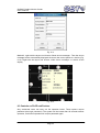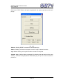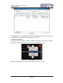
1
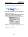
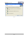
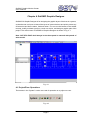
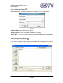
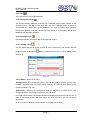
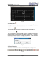
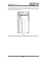
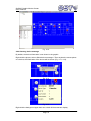
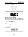
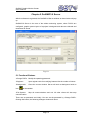
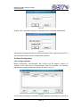
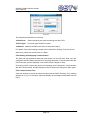
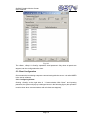
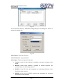
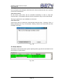
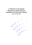
GstGMC Graphic Monitor Center User’s Manual CONTENTS Chapter 1 Overview ...................................................................................................... 1 Chapter 2 System Requirement .................................................................................. 2 2.1 Hardware ............................................................................................................... 2 2.2 Software ................................................................................................................ 2 2.3 Configuration ......................................................................................................... 2 Chapter 3 Installation ................................................................................................... 3 Chapter 4 GstGMC Graphic Designer......................................................................... 5 4.1 Project/Zone Operations ....................................................................................... 5 4.1.1 Creating New Project ................................................................................ 6 4.1.2 Opening Existing Project 4.1.3 Save .......................................................................... 6 ......................................................................................................... 7 4.1.4 Issuing the project .................................................................................... 7 4.1.5 Deleting Project ........................................................................................ 7 4.1.6 Creating a zone ........................................................................................ 7 4.1.7 Delete a zone 4.1.8 Print a zone 4.1.9 Search a device ........................................................................................... 8 ............................................................................................. 8 ....................................................................................... 8 4.2 Device Operation .................................................................................................. 8 4.2.1 Device List ...................................................................................................... 9 4.2.2 Showing device message............................................................................. 10 4.2.3 Device Icon Size ........................................................................................... 11 4.2.4 Align Devices 4.2.5 Delete a Device ........................................................... 11 ...................................................................................... 11 4.3 Picture Operation ................................................................................................ 11 4.4 Complete Procedure for Graphic Designer......................................................... 12 Chapter 5 GstGMC3.0 Server..................................................................................... 13 5.1 Functional Buttons .............................................................................................. 13 5.2 Panel Configuration............................................................................................. 14 5.2.1 Configuring Panels ....................................................................................... 14 5.2.2 Starting and Stopping Communication ......................................................... 15 5.2.3 Communication Test ..................................................................................... 15 Page I GstGMC Graphic Monitor Center User’s Manual 5.3 Client Configuration ............................................................................................. 16 5.3.1 Configuring Clients ....................................................................................... 16 5.3.2 Client control ................................................................................................. 18 5.3.3 Client Test ..................................................................................................... 18 5.4 Status Monitor ..................................................................................................... 18 Chapter 6 GstGMC3.0 Client ...................................................................................... 19 6.1 Login .................................................................................................................... 19 6.2 Display on the Client ........................................................................................... 19 6.2.1 Overview ....................................................................................................... 19 6.2.2 Information .................................................................................................... 20 6.2.3 Auto/Manual Mode for Viewing Zones ......................................................... 21 6.2.4 Zoom ............................................................................................................. 22 6.2.5 Device messages ......................................................................................... 22 6.3 Controls on FACP and Devices .......................................................................... 23 6.3.1 FACP Operation ........................................................................................... 24 6.3.2 Device Operation .......................................................................................... 25 6.3.3 Exit ................................................................................................................ 26 Chapter 7 Caution ....................................................................................................... 26 Page II GstGMC Graphic Monitor Center User’s Manual Chapter 1 Overview GstGMC Graphic Monitor Centre is a newly developed fire alarm system monitoring software. With friendly interface, the software may support 8 remote client stations plus local monitor station, making complete monitoring and control. Also with OLE for Process Control (OPC), the communication with fire alarm control panel(FACP) can also be integrated into other systems. The related FACP include GST200, GST200-2, GST5000 and GST-IFP8. The main features of this highly intelligent package are: The self-reacting communication module automatically maintains data communication with FACP. The operator can test the communication at any time to ensure the reliable running of system. The communication server connects to the FACP directly. The monitor stations can be connected with the server locally or through network. Multi-level password control. Simple, direct and complete user graphics view interface, switching between device layouts of different monitoring zones. Popup of off-normal information automatically, with devices in alarm, action, fault or disabled condition flashing in different colors. Complete functions of database management and data backup ensure system safety by minimizing possibility of data loss. Supporting multi-languages. The language displayed is the same as that of the operating system. Page 1 GstGMC Graphic Monitor Center User’s Manual Chapter 2 System Requirement 2.1 Hardware CPU: Pentium IV 1.7G or above Minimum free Hard disk: 10GB or above Memory: 512M or above 2.2 Software Windows XP Professional(IE6.0 or above)Windows 7 2.3 Configuration The complete system includes FACP (or FACP network), RS232 communication card connecting to FACP, local computer connecting with RS232 card (by serial port), remote monitoring computers (optional, maximum 8) through network. Page 2 GstGMC Graphic Monitor Center User’s Manual Chapter 3 Installation The software setup file is named GstGMC3.0_setup.exe. To install it, just double click the file and follow the instruction. After installation, there will be 3 allocations (Fig. 3-1). Fig. 3-1 GstGMC3.0 Graphic Designer is installed on local computer for displaying the graphic layout. GstGMC3.0 Server is the communication server, installed on the local computer only. This application should be always started. GstGMC3.0 Client is the monitor software, installed on all monitor stations (including local computer). The stations will log onto the server under password control. The server configuration requires a Register Code to setup monitor stations. When it is started the first time, a window will pop up as follows: Fig. 3-2 Send the <User Code> to GST, and inform how many monitor stations are required. GST will provide you with the <Register Code>. Input the code in the blank and click <Register>, the software will start. For uninstalling the software, you can run the setup program again, choose “Remove” in the screen of Fig. 3-3, and then click “Next”. Page 3 GstGMC Graphic Monitor Center User’s Manual Fig. 3-3 Page 4 GstGMC Graphic Monitor Center User’s Manual Chapter 4 GstGMC Graphic Designer GstGMC3.0 Graphic Designer is for designing the graphic layout of devices in a system, so that the user can have an idea of the layout of system devices and quickly locate any off-normal event like fire alarm, fault and action. You can use the buttons in the toolbar to setup, modify or delete a project, a zone or a device, and design a graphic plan of the project. The main screen of GstGMC3.0 Graphic Designer is shown in Fig. 4-1. Note: GST-IFP8 FACP shall always be the host panel in network with panels of other model. Fig. 4-1 4.1 Project/Zone Operations The buttons in the “System” section are used for operation on a project or zone. Fig. 4-2 Page 5 GstGMC Graphic Monitor Center User’s Manual 4.1.1 Creating New Project Clicking this button, the following dialogue box as shown in Fig. 4-3 will appear. Fig. 4-3 <Project Name>: input the title of the project. <Project picture>: insert the building outlook photo (optional). <Zone size>: The size of zones of a project is automatically setup by the software according to the screen resolution on first running. 4.1.2 Opening Existing Project If you want to modify an existing project, pressing this icon, a dialogue box for opening file will appear as shown in Fig. 4-4. The file name is config.xml. Fig. 4-4 Page 6 GstGMC Graphic Monitor Center User’s Manual 4.1.3 Save The user can save the modified project. 4.1.4 Issuing the project The current working database is saved into a separate project folder, named as the <Project name>. The Server can work with only one database, which is saved in <Project\Server> folder. The “Issue” operation will copy all related files including background pictures into the <Project\Server> folder to synchronize the monitor database and definition database. 4.1.5 Deleting Project Pressing this button will delete data of the selected project. 4.1.6 Creating a zone You can define the logical layout (by floor or zone) of devices in the system after the project is setup. Pressing the button, a dialogue box as in Fig. 4-5 for adding a zone will pop up: Fig. 4-5 <Zone Name>: Name of the zone. <Backpicture>: The background picture can be any type of popular picture type, normally converted from AutoCAD project drawing. The picture size should fit the screen resolution (Fig. 4-6). <Backcolor>: Defining the background color of this zone to make device icon distinguished from the background picture of the project. In normal monitor status, the Graphic Monitor will display all pictures of a zone in turn. In case of off-normal events, the front page will show the zone with the off-normal information. Zone name will be displayed at the bottom of the page when rolling. Page 7 GstGMC Graphic Monitor Center User’s Manual Fig. 4-6 4.1.7 Delete a zone Pressing this button will delete a selected zone from current project. The devices already set into this zone will return to device list. 4.1.8 Print a zone The current zone background picture and all devices’ icons will be printed out. 4.1.9 Search a device This is to help finding a device from a big project for modification or replacement. Pressing this button, the system will pop up a dialogue as shown in Fig. 4-7. Entering a 6-digit device number, the system will locate and select the device. If there is duplicated device numbers, you can continue to press “Find” button. Fig. 4-7 4.2 Device Operation The buttons in the “Device edit” section are used for operation on a single device. Fig. 4-8 Page 8 GstGMC Graphic Monitor Center User’s Manual 4.2.1 Device List By choosing “FACPID”, “Loop” and “Zone” on the left middle part of the main screen of Graphic Designer, the left bottom will show all defined devices arranged into the specific loop and zone of a FACP (Fig. 4-9). Fig. 4-9 After all zones are defined, the user can layout the devices of each zone by simply dragging it from the list on the left to the correct position of the zone, as in Fig. 4-10. Page 9 GstGMC Graphic Monitor Center User’s Manual Fig. 4-10 4.2.2 Showing device message By default, the device information is not shown in the graphic. Right-click the picture, select <Show device message>. Then anytime the mouse points on a device, the information of the device will be shown (Fig. 4-11, 4-12). Fig. 4-11 Fig. 4-12 Right-click the background again then can switch off the automatic display. Page 10 GstGMC Graphic Monitor Center User’s Manual 4.2.3 Device Icon Size 4.2.3.1 Setting the size manually Drop down the arrow beside <size> button. Fig. 4-13 The size is default set at large icon (32 pixels). Select the ideal size for the screen resolution. Also a Customized size can be input. Fig. 4-14 4.2.3.2 Resizing a Group of Devices Select a group of devices by mouse, either by left-button-draw or using <Shift>+Left-click. Then click on the wanted operation (same width, same height or same width & height) to change all selected devices to the same size. 4.2.4 Align Devices Manually moved devices do not appear in good alignment normally. These buttons will help to make easy alignment by top, bottom, left, right, central in vertical or middle in horizontal. 4.2.5 Delete a Device Clicking this button can delete the selected device logo from the current page. The device will be back to the list. 4.3 Picture Operation Fig. 4-15 Zoom IN, Zoom OUT and moving the background picture to find the correct location. Page 11 GstGMC Graphic Monitor Center User’s Manual 4.4 Complete Procedure for Graphic Designer 1 Define system text by GstDef3.0 Defining Tool, leaving the project as current working system. Please refer to GstDef3.0 Defining Tool User’s Manual. 2 Add new project. 3 Add zones. 4 Prepare background pictures for each zone. 5 Place all devices into correct positions. 6 Synchronize the database by “Issue”. NOTE: The “Issue” operation must be carried out after every modification to the device definition and graphic design. Page 12 GstGMC Graphic Monitor Center User’s Manual Chapter 5 GstGMC3.0 Server After the software is registered, the GstGMC3.0 Server window as shown below will pop up. GstGMC3.0 Server is the core of the whole monitoring system, where FACPs are configured, graphic system layout of a project is designed and data are collected and transmitted to clients. Fig. 5-1 5.1 Functional Buttons <Change PWD> Modify the operating password. <Register> Input register code for modifying features like the number of clients. <Background> Close the current window. Server will work at background with an icon at the taskbar. <Exit System> communication. Stop all communications and exit. All other clients will also stop There was no password set initially. You can set the password by <Change PWD>. Clicking this button, the following dialogue window will show. Page 13 GstGMC Graphic Monitor Center User’s Manual Fig. 5-2 Clicking <OK>, the system will pop up a dialogue box for confirming the password. Fig. 5-3 Inputting the new password twice to confirm and clicking <OK>, it will become valid. The same procedure is also used for modifying the password. 5.2 Panel Configuration 5.2.1 Configuring Panels Before configuration, communication with FACPs must be stopped. Clicking on <Config> at the right side of “Communication With Fire–controller” and inputting password, the system will pop up a window as shown in Fig. 5-4. Fig. 5-4 You can add new panel(s) or edit/delete existing panel(s) in this dialog box. Here is an Page 14 GstGMC Graphic Monitor Center User’s Manual example for adding new. Fig. 5-5 The parameters should be set correctly. <Serial Port>: Select the serial port used connecting with the FACP. <FACP Type>: The panel type should be correct. <Address>: Address should be the same as the panel setting. For details of the panel settings, please refer to GstDef3.0 Defining Tool User Guide. After setup, select the correct panel to <Start>. 5.2.2 Starting and Stopping Communication The start and stop operation share the same button on the right side. After you have configured communication with the FACP, pressing this button, communication with this FACP will start, and the displayed name of this button changes to Stop. Choosing a FACP, clicking this button and inputting correct password, communication with this FACP will stop, and the displayed name of this button changes to Start again. 5.2.3 Communication Test A test can be done to check the communication with the FACP. Pressing Test, a testing window as in Fig. 5-6 will show, which will display the messages transmitted from the FACP. Page 15 GstGMC Graphic Monitor Center User’s Manual Fig. 5-6 The <Start>, <Stop> & <Config> operations need password. Only when all panels are stopped, can the configuration be done. 5.3 Client Configuration Client means the monitoring computer communicating with the server. It is called USER in the server software. 5.3.1 Configuring Clients Clicking <Config> at the right side of “Communication With Client”and inputting password, the system will pop up a dialogue box as in the following figure (this operation must be done when communications with all clients are stopped). Page 16 GstGMC Graphic Monitor Center User’s Manual Fig. 5-7 You can add new user(s) or edit/delete existing panel(s) in this dialog box. Here is an example for adding new. Fig. 5-8 <User Name>: User name for log in. <User Password>: Log in password. <User Type>: There are 4 types for selection. Local: means the client software is installed on the same computer of the server. Remote: means client software is installed on another computer. The communication can be through network. GstOPC: is the OPC user who integrates the monitoring information of the server into other systems. GSTAPI: is the user of GSTAPI Interface who integrates the monitoring information via this interface. Page 17 GstGMC Graphic Monitor Center User’s Manual <Privilege>: Authorization to the users. For clients who have only Monitor privilege, it can only monitor the messages, while Monitor & Control authorizes the user to operate on the FACP and devices. 5.3.2 Client control On the server, each client can be controlled individually to start or stop their communication. The stopped client(s) will not be possible to log on and communicate. The log on password is only modifiable on the server. 5.3.3 Client Test A test can be done to check the communication with the client. Pressing <Test>, a testing message as in Fig. 5-9 will show. Clicking <Send to All Users>will send this message to all users. Fig. 5-9 5.4 Status Monitor The bottom of the window shows system operating history log with time and date for real time monitor of system status. Fig. 5-10 Page 18 GstGMC Graphic Monitor Center User’s Manual Chapter 6 GstGMC3.0 Client 6.1 Login Fig. 6-1 The Login box will come out when starting the GstGMC3.0 Client. If the client software installed on the same computer of the server, the <Server> should be “localhost”. If the computer connecting through network, you need to input the server IP address here. Input the correct user name and password then click <Login>. The client will communicate with the server and automatically download the database update to local folder. If the client is first time started, it will download the complete database. Fig. 6-2 On the server, the client status will be changed (Fig. 6-3). Fig. 6-3 6.2 Display on the Client 6.2.1 Overview The main screen of Client is shown in Fig. 6-4. The main screen for GST-IFP8 panel is shown in Fig. 6-5. Page 19 GstGMC Graphic Monitor Center User’s Manual Fig. 6-4 Fig. 6-5 After successfully logging on, the client will display the layouts page by page automatically. The current system condition will be shown at the bottom. Clicking the zone in the tree structure on the left, the display will show the layout of the zone. 6.2.2 Information The off-normal conditions of the FACP will be shown by indicators with different colors. The last ALARM message will be shown on the top-centre. The off-normal information will be shown on the right-corner in the form of text. Right-clicking on right corner butter, the window for all abnormal information will pop up Page 20 GstGMC Graphic Monitor Center User’s Manual as shown in Fig. 6-6. Fig. 6-6 6.2.3 Auto/Manual Mode for Viewing Zones On top of the screen there is a tick box for choosing automatically or manually display zone pages. The system defaults to display zone layout automatically by rolling pages. Ticking off the “Auto” option, you can view the zone layouts manually using the buttons TOP, PREV, NEXT and LAST (Fig. 6-7). Or, you can right-click the layout, a menu as in Fig. 6-6, options for viewing different pages will show, where “Lock zone” means manual viewing. Fig. 6-7 Page 21 GstGMC Graphic Monitor Center User’s Manual Fig. 6-8 6.2.4 Zoom There are two ways for zooming. One is using the functional buttons (Fig. 6-9), the other is by right-click commands (Fig. 6-10), and the zoom rate is shown at the bottom of the screen. Fig. 6-9 Fig. 6-10 6.2.5 Device messages The device message is not shown by default. There are two methods for viewing the device details. Method 1, right-click the device and choose <Property> (Fig. 6-11). Page 22 GstGMC Graphic Monitor Center User’s Manual Fig. 6-11 Method 2, right-click the layout and choose <Show device message>. Then the device message will be automatically displayed whenever the mouse points to a device (Fig. 6-12). Right-click the layout and choose <Hide device message> to switch off the display. Fig. 6-12 6.3 Controls on FACP and Devices Only authorized users can carry out the operation below. These options require password (the Login password). The system will be locked after 60 seconds without operation, and further operation will require password again. Page 23 GstGMC Graphic Monitor Center User’s Manual 6.3.1 FACP Operation Click button <FACP Panel> and input the password, the system operation window will pop up. Fig. 6-13 <Reset>: Sending RESET command to reset the panel(s). <Mute>: Sending command to the panel in order to stop all started sounders. <Sys Time>: Sending time synchronization command to the panel. <System Log>: Viewing history messages. By selecting the start and end time and <Query>, all events during the period will be listed (Fig. 6-14). The events can also be printed out. Page 24 GstGMC Graphic Monitor Center User’s Manual Fig. 6-14 If <Realtime Print> is selected, then any off-normal information such as fire alarm, fault or disablement will be automatically printed out in real time. 6.3.2 Device Operation The devices can be started, stopped, disabled (isolation) and enabled (release). Right-click on the device, the command drop list will appear (Fig. 6-15). Fig. 6-15 Operation also can be done under device property window (Fig. 6-16). Page 25 GstGMC Graphic Monitor Center User’s Manual Fig. 6-16 6.3.3 Exit Clicking on the Exit button exits the software. The operation requires password. Chapter 7 Caution The software (server and clients) should be running at all time, to make safety fire alarm monitoring. The copyright of this software is reserved by the manufacturer, and protected by law. Any copy or modification without the permission of the manufacturer is prohibited. For integrating software developing, please contact with the technical support. This user guide may be updated according to product upgrading without notification! Page 26 Gulf Security Technology Co., Ltd. No. 80, Changjiang East Road, QETDZ, Qinhuangdao, Hebei, P. R. China 066004 Tel: +86 (0) 335 8502528 Fax: +86 (0) 335 8508942 [email protected] www.gst.com.cn 30309194