1
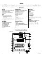
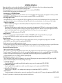
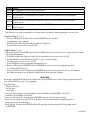
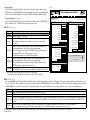
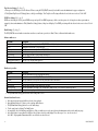
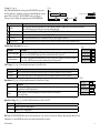
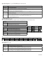
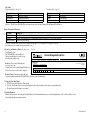
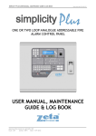
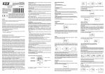
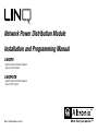
Network Power Distribution Module
Installation and Programming Manual
LINQ8PD
- Network Power Distribution Module
- Eight (8) Fused Outputs
LINQ8PDCB
- Network Power Distribution Module
- Eight (8) PTC Outputs
DOC#: LINQ8PD Rev. 110515
More than just power.™
Overview:
Altronix LINQ8PD(CB) network power distribution module facilitates monitoring, reporting and control of one (1) or two (2) low voltage AC or supervised DC power supply/chargers
over the network. Reports diagnostics via Email/SNMP notifications greatly reducing system downtime and eliminating unnecessary service calls. LINQ8PD(CB) retrofits with most
currently installed multi-output power supply/chargers.
Specifications:
Input Power:
Network Security:
Programming Features:
• Input1/Input2: 12VAC-28VAC @ 12.5 amp each or
12VDC/28VDC @ 12.5 amp each
Note: Do connect AC and DC simultaneously to
INP1 and INP2
• Secure Socket Layer (SSL)
• Power Supply(ies) voltage and load limits (High/Low)
• FACP trigger type (wet or dry-N.O./N.C.)
• Input Function (FACP reset/tamper)
• Output Reset Trigger (N.O./N.C.)
• Battery Monitor Configuration:
- Capacity
- Charge Level
- Max. Charge and Discharge Current
- Service Date
• Configurable Output Relay(s)
• Individual Output Configuration:
- Device ID
- Voltage and Current Limits (High/Low)
- FACP Trigger Setting (latching/non-latching/inactive)
- Battery Backup
Outputs:
• Eight (8) fused or PTC protected outputs:
-LINQ8PD: Blade fuses are rated 3 amps
-LINQ8PDCB: PTCs are rated 2.5 amps
• Power output(s) can be locally or remotely controlled
• Surge Suppression
Status Monitoring:
• Power Supply(ies) output voltage and load
• Voltage and load of each output
• FACP trigger and reset status
• Unit temperature (Celsius)
• Power Supply AC and Battery status
• Battery health
Reporting:
• SNMP trap messages.
• E-mail notifications
• Event Log tracks history
Fire Alarm Interface:
• Supervised FACP disconnect (Latching or Non-Latching)
• FACP reset (N.C. or N.O.)
Mechanical:
• Board Dimensions: 5.5”L x 3.625”W x 0.96”H
(139.7mm x 92.07mm x 24.38mm)
• Product weight (approx.): 0.4 lbs. (0.18kg)
• Shipping weight (approx.): 0.7 lbs. (0.32kg)
Terminal/Connector Identification:
LINQ8PD - Fig. 1
A B C D E
F G
BAT LOCAL
FACP IN -- FACP RLY 2
GND
GND RET -RESET FACP EOL RET+
FACP IN+ FACP RLY 1
H
LINQ8PD
AC
3
FUSE OUT8
3
FUSE OUT7
FUSE OUT6
3
K
NO
BAT
C
L
NO
AC
C
---- OUT1 +
-- OUT2 +
-- OUT3 +
-- OUT4 +
-- OUT5 +
O
- 2 -
3
FUSE OUT5
3
FUSE OUT4
3
FUSE OUT3
3
FUSE OUT2
FUSE OUT1
Fuse Battery
3
I
J
DRY Inputs
P
+ BAT OUT -
Q
15
FACP
+ BAT IN -
R
15
Altronix Corp.
Brooklyn, NY 11220
BAT
-- INP2 +
~
~
S
UPLINK
DOWNLINK
-- INP1 +
~
~
T
<INP1 OFF INP2>
U
15
-- OUT6 +
-- OUT7 +
-- OUT8 +
AC Fail
NC
C
N
NC
C
Battery Fail
M
LINQ8PD/LINQ8PDCB
A
B
C
D
E
F
G
H
I
Terminal/Connector Identification:
A
B
C
D
E
F
G
H
I
J
A
B
C
D
E
F
G
H
I
J
K
J K L
K L M
L M N
M
N
O
P
Q
R
N
O
P
Q
R
S
O
P
Q
R
S
T
Terminal/Legend
A GND,
B C RESET
D E F G H
B C
D FACP
E F EOL
G H I
GND,
C D
E F
+ RET
-- G H I J
D FACP
E F --GINH+ I J K
E FACP
F G RLY
H I 1, J2 K L
F Downlink
G H I J K L M
G H
I J K L M N
Uplink
H BAT
I J Local
K LLED
M N O
I FACP/AC/BAT
J K L M N LEDs
O P
J K
L
M
N
O
Heartbeat LED P Q
K RJ45
L M N O P Q R
L M
N O P Q R S
USB
Battery Fail
M N O P Q R S T
NC, C, NO
AC Fail
N O P Q R S T U
NC, C, NO
+ OUT1 -- to
O P Q R S T U
+ OUT8 -P Q
S C
T U
ACR/ NO,
Q R
S/T
BAT
NO,UC
R +
S BAT
T UOUT -S +
T BAT
U IN --- INP2 +
T U
U -- INP1 +
Description
I J reset.
K L M N O P Q R S T U
FACP
J K L to
M EOL
N O
P QLINQ8PD(CB).
R S T U
Connects
or next
Q R S T U
K L EOL,
M N orOnext
P LINQ8PD(CB).
FACP
Q R +.S T U
L Minput
N from
O P FACP
Wet
M
N reporting
O P Q relay.
R S T U
FACP
N
O P Q toRpower
S Tsupply
U or second LINQ8PD(CB) module.
Connection
O
P Q to
R next
S TLINQ8PD(CB)
U
Connects
upstream from this module. If this is the first LINQ8PD(CB) in the daisy chain this connector is not used.
Q R battery(ies)
P
S T U thresholds.
Indicates
Q
R S status
T U of FACP, AC and Battery.
Indicates
R
S
T
U
Indicates the LINQ8PD(CB) is operational.
SEthernet:
T U LAN or laptop connection enables LINQ8PD(CB) programming and status monitoring.
T
U connection enables LINQ8PD(CB) initial setup and programming.
Laptop
Indicates low battery condition, e.g. connect to alarm panel. Relay normally energized when DC power is present.
U
Contact rating 1 amp @ 30VDC.
Indicates loss of AC power, e.g. connect to audible device or alarm panel. Relay normally energized
when AC power is present. Contact rating 1 amp @ 30VDC (power-limited).
24VAC/28VAC or 12VDC/24VDC continuous output.
Connection to [AC Fail] terminals on power supply.
Connection to [BAT Fail] terminals on power supply.
Connection to stand-by batteries.
Connection to [+ BAT -- ] terminals on power supply.
Second AC or DC power supply input. Note: Do connect AC and DC simultaneously to INP1 and INP2.
First AC or DC power supply input. Note: Do connect AC and DC simultaneously to INP1 and INP2.
LED Diagnostics:
LED
BAT LOCAL
FACP
AC
BAT
OUT1-OUT8
LINQ8PD/LINQ8PDCB
Flash Codes
ON
Blinking
ON
OFF
ON
OFF
ON
OFF
ON
OFF
Blinking
Description
Charge/Discharge current working properly
Charge/Discharge current on the battery exceed limits
FACP triggered
FACP released
Input signal active
Input signal inactive
Input signal active
Input signal inactive
Output is ON and working properly
Output is OFF
Output is ON and voltage and/or current exceeds limits
-3-
Installation Instructions:
Wiring methods shall be in accordance with the National Electrical Code/NFPA 70/NFPA 72/ANSI, and with all local codes and authorities having jurisdiction.
Product is intended for indoor use only and should be installed by qualified personnel.
1. Disconnect the AC mains and batteries (if used) from the power supply(ies) before connecting the LINQ8PD(CB)
2. Mount LINQ8PD(CB) into position and secure with mounting screws.
Interconnecting two (2) LINQ8PD(CB) modules:
Two (2) LINQ8PD(CB)s can be interconnected to enable both units to be accessed from a single IP address. Connect interface cable (supplied) to the interface port marked
[DOWNLINK] of first LINQ8PD(CB) which will be the master to interface port marked [UPLINK] of second LINQ8PD(CB).
3. Power Supply Input Connection:
The LINQ8PD(CB) can be connected to two independent AC or DC power supplies that can be routed thru each of the individual outputs. Each output is equipped with an
input selection switch which is used to route the desired input to the output. This switch also has a center off position that can be used to turn power off to an output.
(a)Single Power Supply Input:
Connect the output of the power supply to the terminals marked [+INP1-] and set the Input selection switch for each output to the [INP1] position.
(b)Dual Power Supply Inputs:
When the use of two independent power supplies is desired connect one power supply to the terminals marked [+INP1-] and the second power supply to the terminals
marked [+INP2-]. Set the Input selection switch for each output to the appropriate position. Reconnect the AC mains of the connected power supply(ies) and verify the
voltage of each of the eight outputs. This helps avoid potential damage. Disconnect the AC mains of the connected power supply(ies).
Note: Do connect AC and DC simultaneously to INP1 and INP2.
4. Output Connections:
Connect devices to be powered to the terminals marked [-OUT1+ to -OUT8+] on LINQ8PD(CB) carefully observing polarity. When two power supplies
are connected to the LINQ8PD(CB) verify that the output voltage matches the operating voltage of the connected devices.
5. Battery Connections:
Skip this step when connecting AC power supplies or DC power supply(ies) without batteries. Connect the power supplies battery charging circuit to the terminals
marked [+BAT IN-], connect the battery leads to the terminals marked [+BAT OUT-].
Note: Do not connect battery(ies) until all connections have been made.
For 24VDC operation connect two 12VDC batteries in series using the supplied yellow battery jumper. For Access Control applications batteries are optional. When batteries
are not used, a loss of AC will result in the loss of output voltage. When the use of stand-by batteries is desired, they must be lead acid or gel type.
6. Battery and AC Supervision Connections:
Skip this step when connecting AC power supplies
These connections are required to monitor AC and Battery Trouble conditions. These conditions cannot be monitored when connected to a non-supervised power supply.
Connect the common (C) and normally open (N.O.) contact of the power supplies AC and Battery supervision relay to the corresponding DRY Inputs of the LINQ8PD(CB).
If required to connect supervisory trouble reporting devices to outputs marked [AC FAIL, BAT FAIL] supervisory relay outputs marked [NC and C]
to appropriate notification devices. Use 22 AWG to 18 AWG for supervision reporting.
7. Fire Alarm Interface options: (not evaluated by UL)
The Fire Alarm Interface and Reset options are programmable via the web interface. FAI input trigger options: supervised normally closed [NC], normally open [NO],
polarity reversal input from signaling circuit or wet input will trigger selected outputs.
(a)Normally Open [NO] input:
Connect the supplied 2.2k resistor (supplied) in parallel with the normally open trigger circuit to the terminals marked [GND, FACP EOL].
(b)Normally Closed [NC] input:
Connect the supplied 2.2k resistor (supplied) in series with the normally closed trigger circuit to the terminals marked [GND, FACP EOL].
(c) Signaling Circuit/Wet input trigger:
Connect the positive (+) and negative (-) of the signaling circuit/wet input trigger to the terminals marked [FACP IN + and [FACP IN -].
(d)Fire Alarm Reset:
If a output is programmed to latch with manual reset connect either a normally open (N.O.) or normally closed (N.C.) dry input to the terminals marked [RESET & GND]
8. Reconnect AC power mains to the connected power supply(ies) and connect back-up batteries.
- 4 -
LINQ8PD/LINQ8PDCB
Establishing Network Connection:
Network Setup - Altronix Dashboard USB Connection
The USB connection on the LINQ8PD(CB) is used for Network and Trap Receiver configuration only. When connected to a PC via the USB cable the LINQ8PD(CB) will receive
power from the USB port allowing programming of the LINQ8PD(CB) prior to being connected to the power supply.
1. Install the software supplied with the LINQ8PD(CB) on the PC being used for programming. This software should be installed on all computers that will have access
to the LINQ8PD(CB).
2. Connect the supplied USB cable to the USB port on the LINQ8PD(CB) and the computer.
3. Click [Dashboard Icon] on the desktop of the computer and open the Dashboard.
4. Click [USB Network Setup] button located in the upper right hand side of the Dashboard. This will open the USB Network Setup screen.
In this screen the MAC Address of the LINQ8PD(CB) module will be found along with the Network Settings, Trap Receiver Settings and SNMP Port Settings.
1. Network Settings (Fig. 2a, pg. 5):
In the IP Address Method field select the method that the IP Address for
the LINQ8PD will be obtained “Static” or “DHCP” then follow the appropriate steps.
STATIC:
Field Name Description
Enter the IP address assigned to the LINQ8PD(CB) by the
IP Address
network administrator.
Subnet Mask Enter the Subnet of the network.
Enter the TCP/IP gateway of the network access point (router)
being used
Gateway
Note: Gateway configuration is required to properly receive emails
from the device.
Enables standard remote access and monitoring. Enter the port
HTTP Port number assigned to the LINQ8PD(CB) module by the network
administrator. Default Port setting 80.*
Enables secure remote access and monitoring. Enter the port numHTTPS Port ber assigned to the LINQ8PD(CB) module by the network administrator. Default Port setting 443.*
Used to update device firmware. Enter the port number
System Port assigned to the LINQ8PD(CB) module by the
network administrator. Default Port setting 667*
a. Click [Submit Network Settings] button, a dialog box will display
“New network settings will take effect after the server is rebooted” click “OK”.
*Note: When remote access is required or using multiple devices on the same
network it is recommended to assign an independent port to each connected device.
Fig. 2
x
Dashboard - USB Network Setup
Linq8
USB Network Settings
MAC Address BC:34:00:30:01:77
A
Network Settings:
IP Address Method:
IP Address:
Subnet Mask:
Gateway:
HTTP Port:
B
Trap Receiver Settings:
Trap Receiver 1 :
STATIC
192.168.168.108
Trap Receiver 2 :
255.255.255.0
Trap Receiver 3 :
192.168.0.11
Trap Receiver 4 :
80
Trap Receiver 5 :
HTTPS Port:
443
System Port:
667
Submit Trap Receiver IP Settings
C
SNMP Port Settings :
Submit Network Settings
SNMP Port : 161
Trap Messages Port : 162
Restore Factory Settings
Submit Port Settings
D
Reboot Server
DHCP (Fig. 2a, pg. 5):
Connect LINQ8PD(CB) to the DHCP router to obtain IP address.
a. After selecting DHCP in the IP Address Method field click [Submit Network Settings] button, a dialog box will display “New network settings will take effect after the
server is rebooted” click “OK”. Next click [Reboot Server] button (Fig. 2d, pg. 5). After the LINQ8PD(CB) reboots the IP address assigned will appear in the IP Address
field. It is recommended to have the assigned IP Address reserved on the router to ensure continued access to the LINQ8PD(CB) (see the network administrator).
LINQ8PD/LINQ8PDCB
-5-
Field Name Description
Subnet Mask When operating in DHCP the router will assign the subnet mask values.
Gateway
Enter the TCP/IP gateway of the network access point (router) being used.
Enables standard remote access and monitoring. Enter the port number assigned to the LINQ8PD(CB) module by the network administrator.
HTTP Port
Default Port setting 80.*
Enables secure remote access and monitoring. Enter the port number assigned to the LINQ8PD(CB) module by the network administrator.
HTTPS Port
Default Port setting 443.*
Used to update device firmware. Enter the port number assigned to the LINQ8PD(CB) module by the network administrator.
System Port
Default Port setting 667*
b. Click [Submit Network Settings] button, a dialog box will display “New network settings will take effect after the server is rebooted” click “OK”.
*Note: When remote access is required or using multiple devices on the same network it is recommended to assign an independent port to each connected device.
2. Trap Receiver Settings (Fig. 2b, pg. 5):
a. Enter up to five SNMP trap receiver IP addresses. When accessing the LINQ8PD(CB) remotely, check with the
network administrator for proper configuration.
b. Click [Submit Trap Receiver IP Settings] button, a dialog box will display “New Trap Receiver
IP settings will take effect after the server is rebooted” click “OK”.
3. SNMP Port Settings (Fig. 2c, pg. 5):
SNMP uses the default port 161 for general SNMP messages and port 162 for SNMP trap messages. In the event these ports need to be changed, enter the new port numbers
assigned by the network administrator.
a. Click [Submit Port Settings] button, a dialog box will display “New Port settings will take effect after the server is rebooted” click “OK”.
b. After all information has been entered, Click [Reboot Server] button (Fig. 2d, pg. 5), a dialog box will display
“Please allow up to 30 sec for the server to reboot”, click “OK”.
c. After the LINQ8PD(CB) has been rebooted all programmed information will be saved.
d. Disconnect the USB cable from the LINQ8PD(CB) module. If the LINQ8PD(CB) has not been connected to the power supply(ies) being monitored,
(refer to Installing LINQ8PD Board on pg. 2).
e. Connect one end of the network cable to the network jack on the LINQ8PD(CB) and the other to the network connection or the PC to be used for programming.
Note: Email notification must be setup via the Browser, Ref to Email Settings in the Browser Setup section of this manual.
Browser Setup
When not using the Altronix Dashboard USB connection for the initial Network setup, the LINQ8PD(CB) needs to be connected to the power supply(ies) being monitored
(refer to Installing LINQ8PD Board on page ??) prior to programming.
Factory Default settings:
• IP Address: 192.168.168.168
• User Name: admin
• Password: admin
1. Set the static IP address for the laptop to be used for programming to the same network IP address as the LINQ8PD(CB) i.e. 192.168.168.200
(default address of the LINQ8PD(CB) is 192.168.168.168).
2. Connect one end of the network cable to the network jack on the LINQ8PD(CB) and the other to the network connection of the laptop.
3. Open a browser on the computer and enter “192.168.168.168” into the address bar. A dialog box Authentication Required will appear requesting both
user name and password enter the default values here.
4. Click [Log In] button. The status page of the LINQ8PD(CB) will appear. This page displays the real time status and health of each power supply connected
to the LINQ8PD(CB).
- 6 -
LINQ8PD/LINQ8PDCB
1. Network setup:
Click [Network Settings] tab. This will open the Network Setting screen. In this screen the
MAC Address of the LINQ8PD(CB) module will be found along with the programming fields
for the Network Settings, Trap Receiver Settings, SNMP Port Settings and Email Settings.
Fig. 3
Device Management Interface
Status
Network Settings (Fig. 3a, pg. 7):
In the IP Address Method field select the method that the IP Address for the LINQ8PD(CB)
will be obtained “Static” or “DHCP” then follow the appropriate steps.
Setup
Network Settings
Events Log
Help
Monday, Sept. 21 2015 [2:30 pm]
Site ID: LINQ8
Network Settings:
IP Address Method: STATIC
A
IP Address: 192.168.168.107
STATIC (Fig. 3a, pg. 7):
Field Name Description
IP Address Enter the IP address assigned to the LINQ8PD(CB) by the network administrator.
Subnet Mask Enter the Subnet of the network.
Enter the TCP/IP gateway of the network access point (router) being used
Gateway
Note: Gateway configuration is required to properly receive emails from
the device.
Enter the HTTP port number assigned to the LINQ8PD(CB) module by the
network administrator to allow remote access and monitoring.
HTTP Port The default inbound port setting is 80. HTTP is not encrypted and unsecure.
Even though HTTP can be used for remote access it is
recommended primarily for use with LAN connections.
Enter the HTTPS port number assigned to the LINQ8PD module by the
network administrator to allow remote access and monitoring.
HTTPS Port
The default inbound port setting is 443. Being encrypted and more secure
HTTPS is highly recommended for remote access.
Used to update device firmware. Enter the port number assigned to the
System Port
LINQ8PD(CB) module by the network administrator. Default Port setting 667*
a. Click [Submit Network Settings] button, a dialog box will display
“New network settings will take effect after the server is rebooted” click “OK”.
Security Settings
Network Settings
D
From: event.report@linqinfo
Subject:
Subnet Mask: 255.255.255.0
Username: event.report
Gateway: 192.168.0.11
Password: • • • • • • • •
HTTP Port: 80
SMTP server IP: smtp.gmail.com
HTTPS Port: 443
SMTP server Port: 587
System Port: 667
Outgoing Email Address 1:
MAC Address: BC:34:00:30:01:72
Outgoing Email Address 2:
Submit Network Settings
Outgoing Email Address 3:
B
Trap Receiver Settings:
Email Settings:
Trap Receiver IP Address 1: 192.168.168.200
Outgoing Email Address 4:
Outgoing Email Address 5:
Submit Test Email
Trap Receiver IP Address 2:
Submit Email Settings
Trap Receiver IP Address 3:
Trap Receiver IP Address 4:
Restore Factory Settings
Trap Receiver IP Address 5:
Submit Trap Receiver IP Settings
SNMP Port Settings:
SNMP Port: 161
E
Reboot Server
C
Trap Message Port: 162
Submit Port Settings
DHCP (Fig. 3a, pg. 7):
After selecting DHCP in the IP Address Method field click [Submit Network Settings] button, a dialog box will display “New network settings will take effect after the server is
rebooted” click “OK”. Next click [Reboot Server] button. After rebooting the LINQ8PD(CB) will be set in the DHCP mode. The IP address will be assigned by the router when
the LINQ8PD(CB) is connected to the network. It is recommended to have the assigned IP Address reserved to ensure continued access (see the network administrator).
Field Name Description
Subnet Mask When operating in DHCP the router will assign the subnet mask values.
Gateway
TCP/IP gateway of the network access point (router) being used will be displayed.
Enter the HTTP port number assigned to the LINQ8PD(CB) module by the network administrator to allow remote access and monitoring. The default inbound
HTTP Port port setting is 80. HTTP is not encrypted and unsecure. Even though HTTP can be used for remote access it is recommended primarily for use with LAN connections.
Enter the HTTPS port number assigned to the LINQ8PD(CB) module by the network administrator to allow remote access and monitoring.
HTTPS Port
The default inbound port setting is 443. Being encrypted and more secure HTTPS is highly recommended for remote access.
Click the [Submit Network Settings] button, a dialog box will display “New network settings will take effect after the server is rebooted” click “OK”.
LINQ8PD/LINQ8PDCB
-7-
Trap Receiver Settings (Fig. 3b, pg. 7):
a. Enter up to five SNMP trap receiver IP addresses. When accessing the LINQ8PD(CB) remotely check with the network administrator for proper configuration.
b. Click [Submit Trap Receiver IP Settings] button, a dialog box will display “New Trap Receiver IP settings will take effect after the server is rebooted” click “OK”.
SNMP Port Settings (Fig. 3c, pg. 7):
SNMP uses the default port 161 for general SNMP messages and port 162 for SNMP trap messages. In the event these port need to be changed enter the new port numbers
assigned by the network administrator. Click [Submit Port Settings] button, a dialog box will display “New SMNP port settings will take effect after the server is rebooted” click
“OK”.
Email Settings (Fig. 3d, pg. 7):
The LINQ8PD(CB) can send emails via an in-house email server, email service provider (i.e. Gmail, Yahoo) or Altronix default email service.
In-house email server:
Field Name
Description
From
Enter the email address assigned to the LINQ8PD(CB) module by the system administrator.
Subject
Identify the location of the v (i.e. the Site ID).
Username
Enter the username associated with the LINQ8PD(CB) module email address.
Password
Enter the username password.
SMTP server IP
Enter the SMTP IP address of the in-house email server.
SMTP server Port
Enter the SMTP port assigned to the in-house email server.
Outgoing Email Address 1-5 Enter up to five outgoing email addresses.
a. Click [Submit Email Settings] button and the email settings will be saved.
Email service provider:
Field Name
Description
From
Enter the email address for the LINQ8PD(CB) module.
Subject
Identify the location of the LINQ8PD(CB) (i.e. the Site ID).
Username
Enter the username associated with the LINQ8PD(CB) module email address.
Password
Enter the username password.
SMTP server IP
Enter the SMTP IP address of the email service provider.
SMTP server Port
Enter the email SMTP port number. The default SMTP email ports are 25 or 465 unless otherwise specified.
Outgoing Email Address 1-5 Enter up to five outgoing email addresses.
a. Click [Submit Email Settings] button and the email settings will be saved.
Altronix default email service:
a. All required sender and network fields have already been populated.
b. Outgoing Email Address 1-5: Enter up to five outgoing email addresses.
c. Click [Submit Email Settings] button to save the email settings.
d. Test the email setup by clicking [Test Email] button.
e. An email will be sent to all Outgoing email addresses. If the test email is not received contact the network administrator and repeat the email setup steps.
f. After all fields have been programed, click [Reboot Server] button, a dialog box will display “Please allow up to 30 sec. for server to reboot”
click “OK”. All programmed information will be saved after the server has rebooted.
- 8 -
LINQ8PD/LINQ8PDCB
Device Management Interface
2.Setup (Fig. 4, pg. 9):
Note: If the Altronix Dashboard is being used for LINQ8PD(CB) setup, refer to
the Folder and Device configuration section in the Altronix Dashboard setup/user
manual. Click on [Setup] tab. The LINQ8PD(CB) setup page will open.
This page is used to configure all operating functions of the LINQ8PD(CB).
Fig.Status
4
Setup
A Site
B C
ID D E F G
A
A B
A B C
A B C D
B
C
D
E
C D E F G
Date/Time
D E F G ID
H
LINQ8PD(CB)
E
F
G
H
PS2 Presence I
F G Presence
H I J
Battery
H
I
J
K
A
Site ID: Enter Location
C
Enter ID
PS1 Volts High Limit
Field Name
Network Settings
Setup
27.7
Security Settings
Help
Monday, Sept. 21 2015 [2:30 pm]
Update Site ID
PS2 Presence No
Update
Events Log
V PS2 Volts High Limit
14
V
D
Battery Presence No
FACP Trigger
E
7
Bat Capacity
Dry
PS1/PS2 Amp Limit
3
0
27.7
3
Latching
Yes
On
2
Enter ID
3
0
27.7
3
Non-Latching
No
On
3
Enter ID
3
0
27.7
3
Inactive
Yes
On
4
Enter ID
3
0
27.7
3
Latching
No
On
5
Enter ID
3
0
27.7
3
Non-Latching
Yes
On
6
Enter ID
3
0
27.7
3
Inactive
No
On
7
Enter ID
3
0
27.7
3
Latching
Yes
On
Off
8
Enter ID
3
0
27.7
3
Non-Latching
No
On
Off
Enter
Fig.
5 ID
Description
Enter both the Voltage Limit High and Voltage Limit Low for the connected power supplies. If either of these
limits are exceeded an SNMP trap message and/or email notification will be generated.
Enter both the Amp Limit High and Amp Limit Low for the connected power supplies. If either of these limits
are exceeded an SNMP trap message and/or email notification will be generated.
Reset
Tamper
Status
Setup
Network Settings
Description
Normally Open reset Trigger Input.
Normally Closed Trigger input.
C
Update
27.7
V PS2 Volts H
PS1 Volts Low Limit
4
V PS2 Volts L
PS1 Amps High Limit 3
PS1 Amps Low Limit
Security Settings
A
C
Enter ID
PS1 Volts High Limit
27.7
Update
Fig.
PS2 Presence No
A PS2 Amps
0
A PS2 Amps
Events Log
Output
Setup
Output
Select
N.O.
N.C.
A
Device Management Interf
Description
PS1 Volts Low Limit 4
When using the FACP Interface with outputs set in latching mode the reset trigger input
PS1 Amps High Limit 3
is designated as the FACP manual release.
PS1
Amps
Low Limit
When the outputs are set in non-latching mode or the FACP interface is
not
being
used 0
the reset trigger input.
Output Reset Trigger (Fig. 6, pg. 9): From the pull down menu select either N.O. or N.C.
Network Se
PS1 Volts High Limit
Description
Update Site ID
Site ID: Enter Location
Input voltage from the fire alarm signal circuit will disconnect all outputs programmed for FACP disconnect.
A short or open on the supervised FACP input will disconnect all outputs programmed for FACP disconnect.
Input Function (Fig. 6, pg. 9): From the pull down menu select either Reset or Tamper.
Select
D
02 /02 / 2015
Enter ID
FACP Trigger (Fig. 6, pg. 9): From the pull down menu select either Wet or Dry.
Select
Wet Trigger
Dry Trigger
AH Battery Service Date
1
Submit Settings
PS1/PS2 Voltage Limit
Minimize Others
Reset
90
% Output Relay 1
PS1 Volts Low Limit 4
V PS2 Volts Low Limit 10.01
V Input Function
Bat Charge Level
Com Trouble
Description
Max Battery
2.75
A Output Relay 2
PS1 Amps High Limit 3
A PS2 Amps High Limit 5
A Output Reset Trigger N.C.
Tamper
Discharge Current
Enter a descriptive name that will identify the location (building, company or campus) where the50 LINQ8PD(CB)
0.9
A Output Relay 3
C Max Charge Current installed.
FACP
H I J K L M N O P Q R S T U PS1 Amps Low Limit 0 A PS2 Amps Low Limit 0 A Max Temp
The Site ID will appear in both the trap message andOutput
email notifications.
Status
Setup
Device ID
Current High (A)
Current Low (A)
Voltage High (V)
Voltage Low (V)
FACP Trigger
Battery Backup
Output Status
Off
I Clicking
J K L
M N Date/Time
O P Qwith
R Computer],
S T U will set the LINQ8PD(CB) to the time of the host computer.
on [Sync
Off
Setup
J Enter
K La descriptive
M N O name
P Qand/or
R location
S T Uof the LINQ8PD(CB).
Off
Off
Site
ID:
Enter
Location
Q Rselect
K From
L MtheNpullOdown
P menu
S T
U
No to disable PS2 if only one power supply is connected.
Off
Q menu
Off
L From
M NtheOpullPdown
R S select
T UNo if batteries are not connected. If batteries are not connected skip this section.
PS1/PS2 Amps/Voltage Limits (Fig. 5, pg. 9):
Field Name
B
Sync with computer
Minimize
Help
Device ID
Curren
1
Enter ID
3
2
Enter ID
3
3
Enter ID
3
6
D
4
5
Enter ID
Battery Presence No
Enter ID
E
3
3
V PS2 Volts High Limit
14
V
FACP Trigger
Enter ID Dry
6
Bat 3Capaci
V PS2 Volts Low Limit
10.01
V
Input Function
Enter ID Reset
7
Bat 3Charge
A PS2 Amps High Limit 5
A
Output Reset
Trigger
Enter ID N.C.
8
Max Batter
3
Discharge
A PS2 Amps Low Limit
A
Max Temp
Device ID
0
Current High (A)
Current Low (A)
C Max Charg
50
Voltage High (V)
Voltage Low (V)
1
Enter ID
3
0
27.7
3
2
Enter ID
3
0
27.7
3
3
Enter ID
3
0
27.7
3
4
Enter ID
3
0
27.7
3
5
Enter ID
3
0
27.7
3
6
Enter ID
3
0
27.7
3
27.7
3
8
Enter ID
3
0
27.7
3
Max Temp: The LINQ8PD(CB) will measure the ambient temperature of the enclosure it is mounted in. Entering a high temperature limit in Celsius,
Enter ID
7
3
0
if this limit is exceeded an SNMP trap message and/or email notification will be generated.
LINQ8PD/LINQ8PDCB
-9Submit Settings
Battery Monitor Configuration (Fig. 7, pg. 10): The LINQ8PD(CB) displays the real time battery health.
Select
Battery Capacity
Battery Charge Level
Max. Battery
Discharge Current
Description
Enter the battery rating in amp hours.
Enter the estimated percentage charge level of the Battery at the time of installation.
Enter the high current limit to be drawn from the battery in the event of a power failure. If this limit is exceeded an
SNMP trap message and/or email notification will be generated.
Enter the maximum charge current of the connected power supply. If this limit is exceeded an SNMP trap message and/or
Max. Charge Current
email notification will be generated.
Enter the date on which the installed batteries need to be serviced. An SNMP trap message and/or email notification will be generated on the entered date.
Battery Service Date Note: Batteries should be inspected at least once a year. Even though the expected battery life is 5 years,
it is recommended changing batteries in 4 years.
Device Management Interface
Device Management Interface
Status
Setup
Network Settings
Security Settings
Events Log
Help
Output Relay configuration (Fig. 7, pg. 10):
Setup
Status
Setupof the
Network Settings
Securityfor
Settings
Log
Help
Three
(3) output relays
LINQ8PD(CB)
can be configured
various uses. Events
From the
pull down
menu select the desired setting for each relay.
A
Site ID: Enter Location
Output Relay 1:
Setup
Setting
Description
Update
Site
ID is detected.
Site AC
ID: Enter LocationThe relay will energize when
AC
trouble
Update
Enter
ID
PS2 Presence No
Com Trouble
The relay will energize when on all trouble conditions.
Output Relay 2:
Battery
Enter
ID
Tamper
PS1 Volts High Limit
A C
PS1 Volts High Limit
C
27.7
V PS2 Volts High Limit
14
V
D
D
Battery Presence No
FACP Trigger
Volts Low Limit 4
V PS2 Volts Low Limit 10.01
V Input Function
The PS1
relay
will energize when
Battery trouble
No is detected.
Update
PS2 Presence
Battery Presence No
Amps
High
Limit 3 when Athe
PS2
Amps High
Limit
5
A Output Reset Trigger
The PS1
relay
will
energize
tamper
input
is triggered.
27.7
V PS2 Volts High Limit
14
V
FACP Trigger
Dry
E
Minimize
AH Battery
Service Date
Minimize
Others
02 /02 / 2015
Dry
Bat Capacity
7
Reset
Bat Charge Level
90
% Output Relay 1
Com Trouble
N.C.
Max Battery
Discharge Current
2.75
A Output Relay 2
Tamper
02 /02 / 2015
FACP
E
7
Bat Capacity
AH Battery Service Date
3
Non-Latching
2
Enter ID
3
Enter ID
4
Current
Enter
ID
5
3Enter ID
0 3
027.7
27.7 3
3
Latching
Enter ID
3Enter ID
6
2
7
Output
Configuration
(Fig. 8, pg. 10):
Enter ID
3
3Enter ID
0 3
027.7
27.7 3
3
Non-Latching
Inactive
0 3
027.7
27.7 3
3
Enter ID
3
0
27.7
3
PS1 Amps Low Limit
Fig. 8
Output
1
0
Device ID
Enter ID
Enter ID
4Field Name
DeviceEnter
ID ID
5
CurrentEnter
High/Low
ID
6
Enter
ID
7Voltage
High/Low
8
Enter ID
A PS2 Amps Low Limit
8
0
High (A)
A
Max Temp
50
3
0
27.7
Current
Low (A)
3
0
Voltage High (V) 27.7
C Max Charge Current
0.9
0
27.7
3
No 3
Relay
Inactive
3
Voltage Low 3(V)
A Output
FACP Trigger
Latching
Inactive
Non-Latching
Latching
Non-Latching
27.7
Description
3
0
3
Latching
Enter a descriptive
name
for
the
device
connected
to
the
output.
3
0
3Submit Settings
Non-Latching
27.7
Enter both the high current limit and low current limit in the appropriate fields for the connected Device.
3 these limits are exceeded
0
3
27.7message and/or email
If either of
an SNMP trap
notification will beInactive
generated.
Enter both
limit in the appropriate
fields for the connected
Device.
3 the high voltage limit
0 and low voltage27.7
3
Latching
If either of these limits are exceeded an SNMP trap message and/or email notification will be generated.
3
Sync with computer
Fig. 7
Discharge Current
27.7
B
Minimize Others
A Output Relay 3
PS1 Amps Low Limit 0
A PS2 Amps Low Limit 0
A Max Temp
50
C Max Charge Current 0.9
Output Relay 3
Reset
90
% Output Relay 1
4
V PS2 Volts Low Limit 10.01
V Input Function
Bat Charge Level
FACP
The relay
the FACP
input
is triggered.
Outputwill energize
Device when
ID
Current
High (A)
Current Low (A)
Voltage High (V)
Voltage Low (V)
FACP Trigger
Battery Backup
Max Battery
willEnter
energize
is triggered.
Output
Reset
Trigger N.C.27.7
2.75Latching A Output Relay
PS1Tamper
Amps High Limit 3 The relay
A1 PS2
Amps
Limit the
5 tamper
A input
Yes2
3
0
3
ID High when
0
Sync with computer
Minimize
Monday, Sept. 21 2015 [2:30 pm]
PS1 Volts Low Limit
3
B
Monday, Sept. 21 2015 [2:30 pm]
Update Site ID
Non-Latching
Yes
Battery Backup
No
Com Trouble
Output Status
Tamper
On
Off
FACPOn
Off
On
Off
Output
Off
On Status
Yes
Yes
OnOn
Off
Off
No
No
OnOn
Off
Off
Yes
Yes
OnOn
Off
Off
No
On
Off
On
Off
Yes
On
Off
No
On
Off
Yes
On
Off
No
On
Off
No
Submit Settings
- 10 -LINQ8PD/LINQ8PDCB
FACP Trigger (Fig. 8, pg. 10): From the pull down menu select how the output will operate when the FACP input is triggered.
FACP Trigger Setting Function/Description
Inactive
The selected output will not switch when the FACP input is triggered.
Non Latching
The selected output will switch when the FACP input is triggered and reset when the FACP trigger input is returns to a non-triggered state.
The selected output will switch to a latched position when the FACP input is triggered. The selected output will remain latched until
Latching
the Output Reset is triggered.
Battery Backup (Fig. 8, pg. 10): From the pull down menu select Yes if the output will remain ON in the event of a power failure.
Select No if the output will turn OFF in the event of a power failure.
Output Status (Fig. 8, pg. 10): Output Status indicates if the output is On (powered) or Off (not powered).
The output can be turned on or off the clicking [On/Off] button. After all fields have been programmed, click on [Submit Setting] button,
a dialog box will display, New Setting Submitted click “OK”. All programmed information in now saved.
3. Security Settings (Fig. 9, pg. 11):
Click on [Security Settings] tab. The LINQ8PD(CB) security setting page will open. This section is used to enable/disable Secure Socket Layer (SSL) and to change
Username and Password. SSL will encrypt all the communication
Fig. 9
with a secure key. An SSL certificate could be self-signed
Device Management Interface
or obtained from a third party certification company.
SSL Certificate Setting (Fig. 9a, pg. 11):
Generating a self-signed SSL Certificate and Key.
Field Name
Description
Two letter code representing the state
State
where the organization is located.
Location
The city where the organization is located.
The legal name of the organization.
Organization
This should not be abbreviated, and should
include suffixes such as Inc., Corp, or LLC.
Unit Name
Name of the device.
Domain name or IP address of the server. This is
Common Name
typically assigned by the network administrator.
Email Address
An email address used to contact the organization.
Status
Setup
Network Settings
Security Settings
Events Log
Help
Security Settings
eFlow
Monday, Sept. 21 2015 [2:30 pm]
Site ID: LINQ8
A
SSL Certificate Settings:
State:
SSL Status:
Certificate Status: No Cert
B
Key Status: No Key
Locality:
SSL State:
Organization:
Unit Name:
Off
Turn SSL On
Change Username and Password:
Common Name:
Username:
Email Address:
C
Password:
Submit SSL Settings
Confirm Password:
Save Username and Password
After all fields have been completed click [Submit SSL Settings] button, a dialog box will appear “Please allow up to 30 sec for server to reboot” click “OK”.
A self-signed SSL certificate will be generated with the information provided in the “SSL certificate settings” fields. The certificate will be valid for 500 days, and time stamped
with the time settings present on the LINQ8PD(CB) module. The date and time must be synced with the host computer before generating an SSL certificate.
Using a private SSL certificate and Key:
Private SSL Certificates and Keys must be uploaded using the Altronix Dashboard. For additional information refer to the Altronix Dashboard setup/user
manual section “Updating firmware / SSL certificate and Key”.
LINQ8PD/LINQ8PDCB
- 11 -
SSL Status:
Certificate Status (Fig. 9b, pg. 11):
Message
Certificate OK
Bad Certificate
No Certificate
Key Status (Fig. 9b, pg. 11):
Descriptions
Valid SSL Certificate.
Invalid SSL Certificate.
A Valid SSL Certificate has not been loaded.
Message
Key OK
Bad Key
No Key
Descriptions
Valid SSL Key.
Invalid SSL Key.
A valid SSL Key has not been loaded.
SSL State: The SSL of the LINQ8PD(CB) can be turned on and off by clicking [Turning SSL On/Turning SSL Off] button.
Change Username and Password:
Field Name
Description
Username
Enter the new Username (up to 32 characters) required to access the LINQ8PD(CB).
Password
Enter the new Password (up to 32 alpha numeric characters) required to access the LINQ8PD(CB).
Confirm Password
Re-enter the new Password.
Click [Save Username and Password] button, a dialog box with appear, “New settings have been applied” click “OK”.
After saving, the new username and password will be active.
4. Event Log and Heartbeat Timer (Fig. 10, pg. 12):
Click [Event Log] tab.
The LINQ8PD(CB) event log will open.
This screen will display the event log along
with the heartbeat timer setup.
Event Log: The event log will display the
50 most recent events.
To update the Event Log click [Display/Refresh Log]
button, the most recent events will be displayed.
Fig. 10
Device Management Interface
Status
Setup
Network Settings
Security Settings
Events Log
Help
Event Log
Site ID: LINQ8
Display/Refresh Log
v1.99.22
Monday, Sept. 21 2015 [2:30 pm]
Last updated:
Heartbeat Timer Settings
Heartbeat Timer Settings:
1
Days
0
Hours 0
Minutes
0
Seconds
Submit
Heartbeat Timer: The heartbeat timer will send
a trap message indicating that the LINQ8PD(CB) is still connected and communicating.
5. Setting the Heart Beat Timer:
a. Click the button labeled Heartbeat Timer Setting.
b. Select the desired time between heartbeat messaging in the Days, Hours, Minutes and Seconds in corresponding fields.
c. Click the button labeled Submit to save setting.
6. Updating Firmware:
Firmware updates must be done using the Altronix Dashboard. For additional information refer to the Updating firmware / SSL certificate and Key section
in the Altronix Dashboard setup/user manual.
- 12 -LINQ8PD/LINQ8PDCB
Fig. 11
Device Management Interface
Status
Setup
Network Settings
Security Settings
Events Log
Help
v1.99.22
Status
Monday, Sept. 21 2015 [2:30 pm]
Site ID: LINQ8
Minimize
LINQ8PD ID: LINQ8 DEV
PS1 Output Voltage
PS1 Load
PS2 Output Voltage
PS2 Load
Output
A
27.5 VDC
2.55 A
13.7 VDC
2.55 A
FACP Status
Reset
Tamper Status
Temperature
B
Normal
Not Triggered
31 C
AC Status
Battery Status
Battery Capacity
Battery Voltage
C
Normal
Normal
7 AH
27.3 V
Battery Charge Level
Battery Current
Battery Condition
Battery Service Date
D
100 %
0 A Charging
Normal
11/05/2018
Device ID
Output Current (A)
Output Voltage (VDC)
Lobby
2.3
27
Normal
Main Office
0.5
13.6
Latching
3
Graphics Department
1.2
27.3
Inactive
4
SMD Machinery
0.7
27.2
Normal
5
Production
0.5
27.3
Latching
6
Shipping
0
27.3
Inactive
7
Receiving
0
27.2
Normal
8
Loading Docks
0
27.3
Latching
1
2
E
Minimize Others
FACP Status
Connection Status: OK
Status Identification:
A
A B
A B C
B C D
Fields
PS1/ PS2
A B C D E F G H
Output Voltage & Load
FACP Status
Reset
B C
D E F G H I
Tamper Status
Temperature
AC Status
Battery Status
C D E F G H I J
Battery Capacity
Battery Voltage
Battery Charge Level
Battery Current
D E F G H I J K
Battery Condition
Battery Service Date
Output 1-8
Device ID
E Output
F G H
I J(A)
K L
Current
Output Voltage (V)
FACP Status
LINQ8PD/LINQ8PDCB
Description
Q 2
IIndicates
J K Power
L M Supply
N O P1 and
R output
S T voltage
and load.
U
Indicates if FACP is triggered or not triggered.
if FACP
triggered
not triggered.
JIndicates
K L M
N O Reset
P Qis R
S T or
U
Indicates if Tamper is triggered or not triggered..
Indicates unit temperature (Celsius).
Indicates AC trouble contact status.
Indicates Battery trouble contact status.
K L M N O P Q R S T U
Indicates Amp/Hour rating of the connected battery(ies).
Indicates battery voltage of the connected battery(ies).
Indicates the charge level of the connected battery(ies).
Indicates the battery charge/discharge rate in amps.
L M N O P Q R S T U
Indicates the condition of the connected battery(ies).
Indicates the next service date of the connected battery(ies).
Indicates output.
Descriptive name for the device connected to the output
MIndicates
N O output
P Q load
R Sin Tamps.
U
Indicates output voltage in volts.
Indicates FACP status of the output.
- 13 -
Notes:
- 14 -LINQ8PD/LINQ8PDCB
Notes:
LINQ8PD/LINQ8PDCB
- 15 -
Notes:
Altronix is not responsible for any typographical errors. Product specifications are subject to change without notice.
140 58th Street, Brooklyn, New York 11220 USA, 718-567-8181, fax: 718-567-9056
website: www.altronix.com, e-mail: [email protected], Made in U.S.A.
IILINQ8PDK02O
MEMBER
- 16 -LINQ8PD/LINQ8PDCB