1
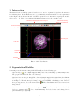
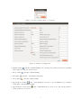
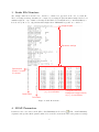
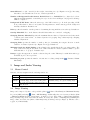
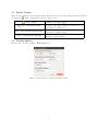
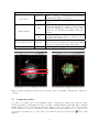
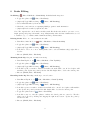
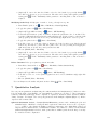
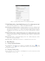
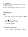
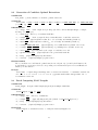
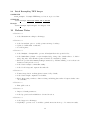
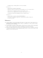
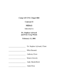
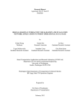
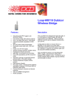
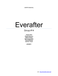
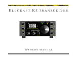
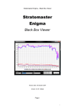
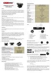
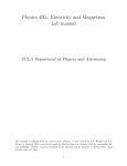
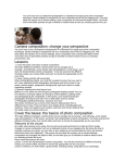
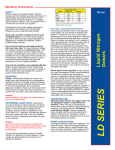
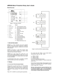
SOA
User’s Guide
by Ting Xu and Eddy Yusuf
Version 3.5.9, July 16, 2015
Contents
1 Introduction
2
2 Segmentation Workflow
2
3 Snake File Structure
4
4 SOAX Parameters
4.1 SOAC Initialization . . . . . . . . . . . . . . . . . . . . . . . . . . . . . . . . . . . . . . . . .
4.2 SOAC Convergence . . . . . . . . . . . . . . . . . . . . . . . . . . . . . . . . . . . . . . . . . .
4.3 SOAC Evolution . . . . . . . . . . . . . . . . . . . . . . . . . . . . . . . . . . . . . . . . . . .
4
5
5
5
5 Image and Snake Viewing
5.1 Mouse Control . . . . .
5.2 Image Viewing . . . . .
5.3 Snakes Viewing . . . . .
5.4 Viewing Options . . . .
5.5 Comparing Snakes . . .
6
6
6
7
7
8
.
.
.
.
.
.
.
.
.
.
.
.
.
.
.
.
.
.
.
.
.
.
.
.
.
.
.
.
.
.
.
.
.
.
.
.
.
.
.
.
.
.
.
.
.
.
.
.
.
.
.
.
.
.
.
.
.
.
.
.
.
.
.
.
.
.
.
.
.
.
.
.
.
.
.
.
.
.
.
.
.
.
.
.
.
.
.
.
.
.
.
.
.
.
.
.
.
.
.
.
.
.
.
.
.
.
.
.
.
.
.
.
.
.
.
.
.
.
.
.
.
.
.
.
.
.
.
.
.
.
.
.
.
.
.
.
.
.
.
.
.
.
.
.
.
.
.
.
.
.
.
.
.
.
.
.
.
.
.
.
.
.
.
.
.
.
.
.
.
.
.
.
.
.
.
.
.
.
.
.
.
.
.
.
.
.
.
.
.
.
.
.
.
.
.
6 Snake Editing
9
7 Quantitative Analysis
8 Miscellaneous
8.1 Viewing Sequential Evolution
8.2 Managing Viewing Angle . .
8.3 Program Snapshot . . . . . .
8.4 Viewing Local Image SNR . .
8.5 Extraction on 2D Images . .
10
.
.
.
.
.
.
.
.
.
.
9 Commandline Usage
9.1 Running SOAX in batch mode .
9.2 Generation of Candidate Optimal
9.3 Batch Computing SOAC Lengths
9.4 Batch Resampling TIFF Images .
.
.
.
.
.
.
.
.
.
.
.
.
.
.
.
.
.
.
.
.
.
.
.
.
.
.
.
.
.
.
.
.
.
.
.
.
.
.
.
.
.
.
.
.
.
.
.
.
.
.
.
.
.
.
.
.
.
.
.
.
.
.
.
.
.
.
.
.
.
.
.
.
.
.
.
.
.
.
.
.
.
.
.
.
.
.
.
.
.
.
.
.
.
.
.
.
.
.
.
.
.
.
.
.
.
.
.
.
.
.
.
.
.
.
.
.
.
.
.
.
.
.
.
.
.
.
.
.
.
.
.
.
.
.
.
.
.
.
.
.
11
11
11
12
12
12
. . . . . . .
Extractions
. . . . . . .
. . . . . . .
.
.
.
.
.
.
.
.
.
.
.
.
.
.
.
.
.
.
.
.
.
.
.
.
.
.
.
.
.
.
.
.
.
.
.
.
.
.
.
.
.
.
.
.
.
.
.
.
.
.
.
.
.
.
.
.
.
.
.
.
.
.
.
.
.
.
.
.
.
.
.
.
.
.
.
.
.
.
.
.
.
.
.
.
.
.
.
.
.
.
.
.
.
.
.
.
.
.
.
.
.
.
.
.
.
.
.
.
12
12
13
13
14
.
.
.
.
.
.
.
.
.
.
.
.
.
.
.
.
.
.
.
.
.
.
.
.
.
.
.
.
.
.
10 Release Notes
14
1
1
Introduction
This manual describes SOAX program and teaches how to use it to segment biological network structures
from 3D image data. It also illustrates how to get quantitative measurements based on the segmentation
results. Figure 1 shows the user interface of SOAX program. For more information regarding the method,
please refer to [1, 2]. Here we use snakes and SOACs interchangeably for the centerline curves.
Window title showing the current image file
Corner texts showing
the current snake file
Corner text showing
intensity range
Bounding box
Cube axes
Orientation
marker
Temporary
message
Figure 1: SOAX User Interface
2
Segmentation Workflow
Segmenting a network structure using SOAX GUI usually needs the following steps:
1. Open an image ( | File > Open Image) in TIFF (*.tif, *.tiff) or MetaImage (*.mhd, *.mha) format.
The program remembers the last opened directory.
2. (Optional) Save an isotropic image (File > Save as Isotropic Image) if the original image has different
voxel spacing in z-axis than that of x and y-axis. This prompts the ratio between z and xy spacing
as in Figure 2. Then the interpolated image can be saved in TIFF or MetaImage format. After the
isotropic image is saved, close the current session ( | File > Close Session) and load the new isotropic
image instead.
3. Set snake parameters in the Parameter Settings panel ( | Tools > Parameters). One can also directly
load a text parameter file (
| File > Load Parameters). The loaded values can be changed in the
panel afterwards (see Figure 3).
2
Figure 2: Specify z spacing relative to xy spacing.
Figure 3: Parameter Settings panel.
4. Initialize snakes ( | Process > Initialize Snakes). One can change the parameters and then re-initialize
snakes without closing the current session.
5. Evolve snakes (
6. Cut snakes (
7. Group snakes (
| Process > Deform Snakes).
| Process > Cut Snakes at Junctions)
| Process > Group Snakes)
8. (Optional) Save snakes (
| File > Save Snakes) in a text file or save in JFilament [3] compatible
format (File > Save JFilament Snakes).
9. (Optional) Close current session (
setting persists across sessions.
| File > Close Session) and go back to step 1. The current parameter
3
3
Snake File Structure
The example snake file is shown below. Junction coordinates are appended at the end of a snake file.
The local background image intensities are computed by averaging the pixel intensities sampled in the local
annulus neighborhood (see “Number of Background Radial Sectors, Radial Near Rnear and Radial Far Rf ar ”
in Section 4.3). Moreover, only pixel intensities higher than “Minimum Foreground” are considered.
Image file path
Parameter settings
Open/closed
Snake: 1 is open;
0 is closed
(x, y, z) coordinates
Snake index
Point index
Foreground and local
background image intensity
at (x, y, z) coordinates
Figure 4: Snake file structure.
4
SOAX Parameters
Parameters can be saved in a text file (File > Save Parameters) and loaded by ( | File > Load Parameters).
A parameter file specifies all the parameters listed below and its content is the same as the parameter settings
4
part of a snake file (see Figure 4).
Two most important parameters are “Ridge Threshold τ ” and “Stretch Factor kstr ”. The former controls
how many snake are initialized and the latter controls how much snakes elongate.
4.1
SOAC Initialization
Intensity Scaling multiplies the intensity of every pixel such that the range of rescaled intensities lie
roughly between 0.0 and 1.0. This allows using a standard range of α, β and other parameters below.
Leave fixed for a given set of images. Set this value to 0 for automatic scaling, where the maximum
intensity is scaled to exact 1.0.
Gaussian std σ (in pixels) controls the amount of Gaussian smoothing in the computation of image gradient (See Section 2.1 and Equation 3 in [2]). Set σ < 0.01 to disable smoothing.
Ridge Threshold τ (also “grad-diff”) controls the number of initialized snakes (see Section 2.2.1 in [2]).
Decrease this value to initialize more snakes.
Minimum and Maximum Foreground specifies the range of intensities intended for extraction. Snakes
are not initialized where the image intensity is below “background” or above “foreground”. During
evolution, stretching force is zero when the intensity at a snake tip is outside this range.
Snake Point Spacing δ (in pixels) specifies the spacing between consecutive snake points (see the end of
Section 2.1 in [2]).
Init z toggles the initialization of snakes along z-axis. Uncheck it to eliminate snakes that are perpendicular
to filaments due to anisotropic PSF with larger spreading along z-axis.
4.2
SOAC Convergence
Minimum Snake Length (also “minimum-size”, in pixels) specifies the minimum length of a resultant
snake. Increase the value to eliminate hair-like snake structures as well as to avoid the snakes picking
up actin patches in yeast images.
Maximum Iterations specifies the maximum number of iterations allowed in each snake evolution.
Check Period specifies the cycle of checking for convergence in number of iterations. A value of 100 means
a snake is checked for convergence every 100 iterations. (see the last sentence of Section 2.1 in [2]).
Change Threshold (in pixels) specifies the threshold of change for a snake to be converged. A value of
0.05 means a snake is converged if every snake point drifts less than 0.05 pixels since last check for
convergence (see the last sentence of Section 2.1 in [2]).
4.3
SOAC Evolution
Alpha α is the weight of first order continuity of snake (see Equation 1 in [2]). This term describes the
energy penalty to elongate snakes. For images with dim linear structures and bright spots, one may
want to use small value of alpha. Default is 0.01.
Beta β is the weight of second order continuity of snake (see Eq.1 in [2]). This term describes the snake
bending energy penalty. Use larger value to make snakes more straight. Default is 0.1.
Gamma γ controls the step size of the iterative process of snake evolution. The smaller gamma is, the
faster snakes converge but the result is less accurate (see Equation 6 in [2]).
External Factor kimg (also “weight”) is the weight of image forces (image gradient) (see Equation 2 in
[2]). Increasing this value to make snakes follow more closely the local shape of filaments.
5
Stretch Factor kstr (also “stretch”) is the weight of stretching force (see Equation 2 in [2]). Increasing
this value to stretch snakes more in case of under-segmentation.
Number of Background Radial Sectors, Radial Near Rnear , Radial Far Rf ar define the local annulus from which magnitude of stretching forces (see Section 2.1.1 and Figure 3 in [2]) and local image
SNR are computed.
Background Z/XY Ratio defines the anisotropy of the PSF of microscope. It is the spreading of PSF
along z-axis relative to that of x and y-axis. Set this parameter to fix the anisotropy in the background
intensity calculation. Default is 1.0.
Delta specifies the number of snake points for determining the tangential direction at the tip. Default is 4.
Overlap Threshold Dmin is the distance threshold that snakes are considered overlapping.
Grouping Distance Threshold specifies the maximum distance that two T-junctions formed after snake
evolution can be clustered into one clustered junction for grouping. Large values may help collapsing
unwanted T-junctions.
Grouping Delta specifies the number of snake points for determining the tangent direction of snake
branches of a clustered junction (see Equation 9 in [2]). Default is 8.
Minimum Angle for SOAC Linking θ (in radians) is the angular threshold for grouping snakes. The
angle between the tangent directions of two snake branches in a clustered junction must be greater
than this value to be grouped. Default is 2π/3.
Damp z toggles the suppression of snake evolution along the z-axis. This may be useful when anisotropy
in PSF along z becomes a problem.
Iteration per press specifies the number of iterations for evolving a single snake (
One Snake).
5
5.1
| Process > Deform
Image and Snake Viewing
Mouse Control
Gestures of mouse navigation in the rendering window are:
Button
Left
Middle
Right
5.2
On Slice Planes
Show image voxel location and intensity
Change window (horizontal drag) or level
(vertical drag) on the selected slice plane
Move the selected slice plane along its normal direction
Anywhere else
Change viewing angle
Translate image at a given viewing angle
Zoom in/out at a given viewing angle
Image Viewing
Image can be inspected by three orthogonal slice planes ( | View > Slice Planes) and Maximum Intensity
Projection (MIP) rendering ( | View > MIP Rendering). Additionally, there are Orientation Marker (View
> Orientation Marker) showing current image orientation, Corner Texts (View > Corner Texts) displaying
image intensity range and loaded snake file names, Bounding Box (View > Bounding Box) delimiting the
image volume, and Cube Axes (View > Cube Axes) acting as an image ruler (see Figure 1). All these can be
toggled on/off individually.
6
5.3
Snakes Viewing
There are four exclusive modes for snake viewing. Only one mode is enabled at a time. Junctions shown in
green spheres ( | View > Junctions) can also be toggled on/off.
| View > Snakes
| View > Show Snakes Locally
View > Color Snakes by Azimuthal Angle
View > Color Snakes by Polar Angle
5.4
Default mode for snake display.
Display snake locally within a small range of selected
slice plane. The clipped snakes are updated accordingly as the slice plane moves.
Color snakes based on its orientation (azimuthal angle
in spherical coordinate system)
Color snakes based on its orientation (polar angle in
spherical coordinate system)
Viewing Options
Options can be accessed via View > Options (Figure 5).
Figure 5: Options related to image and snake viewing.
7
View Options
Adjusts image contrast. The default is Imax − Imin ,
where Imax and Imin are the maximum and minimum
Window
intensities in the image, respectively.
Adjusts image brightness. The default is (Imax +
Level
Imin )/2.
Minimum image intensity shown in MIP rendering. Intensities less than Min are displayed completely transparent. The default is Imin + 0.05 ∗ (Imax − Imin ). The
Min
opacity increases linearly for intensities between Min
and Max.
Image intensity saturated in MIP rendering. Intensities greater than Max are displayed completely opaque
Max
and white. The default is Imax .
Only snakes that lie between position of selected slice
plane ± Interval are displayed (see Figure 6(a)). This
Interval
helps reduce clutter when viewing dense snakes.
Segment size Minimum size of a uniform-color snake segment.
Slice Planes
MIP Rendering
Show Snakes Locally
Color Snake Orientation
2 x Interval
(a)
(b)
Figure 6: (a) Showing snake locally around a certain slice plane. (b) Visually comparing three different set
of snakes.
5.5
Comparing Snakes
Up to three set of snakes can be loaded simultaneously for comparison (see Figure 6(b)). Start by loading
the first result (File > Load Snakes), then the second (File > Compare Snakes) and the third (File > Compare
Another Snakes). The loaded snake file names are displayed on the upper right corner of the rendering
window, which can be turned on/off (View > Corner Texts). If any other result needs to be compared, one
can directly load it using any one of these three actions without closing the current session ( | File > Close
Session).
8
6
Snake Editing
No Editing (
| Edit > Edit Mode > Normal Mode). Individual snake inspection.
1. Toggle slice planes off (
| View > Slice Planes)
2. (Optional) Toggle MIP rendering off (
| View > MIP Rendering)
3. Select individual snake by left mouse click
4. Check the console window accompanying SOAX program for snake information
5. (Optional) Deselect snake by right mouse click
Note: The output in the console window includes snake ID, whether the snake is open curve or not,
length, spacing, and point position with corresponding intensity, where the first column is index, second
to fourth are x, y, z coordinates, fifth column shows snake point intensities.
Deleting Snakes Delete one or more snakes from result.
1. Turn Delete Snake Mode on (
2. Toggle slice planes off (
| Edit > Edit Mode > Delete Snake Mode)
| View > Slice Planes)
3. (Optional) Toggle MIP rendering off (
| View > MIP Rendering)
4. Left click to select one or more snakes (snakes can be selected simultaneously); right click to
deselect
5. Execute (SPACE | Edit > Edit Snake)
Trimming Snake Tip Cut part of a snake from its tip.
| Edit > Edit Mode > Trim Tip Mode)
1. Turn Trim Tip Mode on (
2. Toggle slice planes off (
| View > Slice Planes)
3. (Optional) Toggle MIP rendering off (
| View > MIP Rendering)
4. Left click a point on a snake to indicate from where the snake will be cut off. A red sphere will
mark the point. Update the point by another left click. Right click to deselect the current point.
5. Execute (SPACE | Edit > Edit Snake)
Extending Snake Tip Extending a snake tip to a new location.
1. Turn Extend Tip Mode on (
2. Toggle slice planes off (
| Edit > Edit Mode > Extend Tip Mode)
| View > Slice Planes)
3. (Optional) Toggle MIP rendering off (
| View > MIP Rendering)
4. Left click a point on a snake to indicate from which end to extend. A red sphere will mark the
point. Update the point by another left click. Right click to deselect the current point.
5. Toggle slice planes back on (
| View > Slice Planes)
6. Left click on any one of the slice planes to indicate the desired position to extend to. The slice
planes can be moved by holding and dragging the right mouse button. Update the point by
another left click.
7. Execute (SPACE | Edit > Edit Snake)
9
8. (Optional) To remove the introduced kink, evolve the edited snake by repeatedly clicking
.
One click evolve Iterations per press iterations. The value can be changed through the parameter
setting panel ( | Tools > Parameters). Other parameter controlling snake evolution can also be
adjusted.
Modifying Snake Body Modify part of a snake to let it go through a new point.
1. Turn Trim Body Mode on (
2. Toggle slice planes off (
| Edit > Edit Mode > Extend Tip Mode)
| View > Slice Planes)
3. (Optional) Toggle MIP rendering off (
| View > MIP Rendering)
4. Consecutively left click two points on a snake to indicate the part that needs to be modified. Two
red spheres will mark the interval and the snake will turn cyan. Update points by other left clicks
(The program updates the first and second point alternately). Right click to deselect a point.
5. Toggle slice planes back on (
| View > Slice Planes)
6. Left click on any one of the slice planes to indicate the desired position to modify the interval
indicated by the first two points. The slice planes can be moved by holding and dragging the
right mouse button. Update the point by another left click.
7. Execute (SPACE | Edit > Edit Snake)
.
8. (Optional) To remove the introduced kink, evolve the edited snake by repeatedly clicking
One click evolve Iterations per press iterations. The value can be changed through the parameter
setting panel ( | Tools > Parameters). Other parameter controlling snake evolution can also be
adjusted.
Delete Junctions Delete green junction points from results.
1. Turn Delete Junction Mode on (
2. Toggle slice planes off (
| Edit > Edit Mode > Delete Junction Mode)
| View > Slice Planes)
3. (Optional) Toggle MIP rendering off (
| View > MIP Rendering)
4. Left click to select one or more junctions (junctions can be selected simultaneously); right click
to deselect
5. Execute (SPACE | Edit > Edit Snake)
User can always save the snakes and junctions after editing (
7
| File > Save Snakes).
Quantitative Analysis
User can perform quantitative analysis using the resultant snakes in the Analysis menu [1]. Snakes are either
loaded from file (File > Load Snakes) or at least finish the evolution process (Step 5 of the Segmentation
workflow). Currently SOAX supports the computation of spherical orientation, radial orientation, filament
density, curvature, and length. User can specify parameters in the Analysis > Options (Figure 7). All the
output are CSV formatted files.
Spherical Orientation Analysis > Compute Spherical Orientation generates a file containing the polar and
azimuthal angles of filament local tangents inside a spherical confinement. A user needs to specify the
x, y, z coordinates of the Center, the Radius of spherical confinement, and a Inside Ratio. Only local
tangents that are within distance of Inside Ratio * Radius to the Center are considered. If the Exclude
points near image boundary is checked, snake points that are within 2 pixels from the image boundary
are excluded from the computation.
10
Figure 7: Specifying analysis parameters in the Analysis Options panel.
Radial Orientation Analysis > Compute Radial Orientation generates a file containing angles between filament local tangents and the outward radial direction with respect to the radius in a spherical confinement. User needs to specify the x, y, z coordinates of the Center and Pixel Size.
Filament Density and Intensity Analysis > Compute Point Density generates a file containing the snake
point density and intensity as well as the voxel intensity with respect to the radius in a sperical confinement. User needs to specify the x, y, z coordinates of the Center, the Radius of spherical confinement,
the Inside Ratio and the Pixel Size. Only points and voxels that lie within Inside Ratio * Radius are
considered.
Filament Curvature Analysis > Compute Curvature generates a file containing curvature (µm−1 ) of filaments. User can specify the Pixel Size and Coarse Graining. If the Exclude points near image boundary
is checked, snake points that are within 2 pixels from the image boundary are excluded from the
computation.
Filament Length Analysis > Compute Snake Length generates a file containing lengths (µm) of all the
snakes. User can specify the Pixel Size.
All in One Analysis > Compute All generates all the above analysis files in the specified folder.
8
8.1
Miscellaneous
Viewing Sequential Evolution
The sequential snake evolution process can be displayed for an inquisitive mind. Instead of
| Process
> Deform Snakes, one can use
| Process > Deform Snakes in Action after snake initialization (Step 4 in
the Segmentation Workflow).
8.2
Managing Viewing Angle
Current viewing angle can be loaded (Tools > Load Viewpoint) from a text file (*.cam) and saved (Tools
> Save Viewpoint) as a text file (*.cam).
11
8.3
Program Snapshot
One can take snapshot (Tools > Take Snapshot) of the current rendering window and save as an image file
(*.png). The program also automatically writes a copy in TIFF format. Note: one needs to specify the
“.png” suffix when prompted the file name.
8.4
Viewing Local Image SNR
One can also view the local image SNR by clicking on the snakes. The console window outputs information on
the selected snake which includes the local image SNR value. To change the size/position of local background
| Tools > Parameters and change the values of “Radial Near” and “Radial Far”.
annulus, one can go to
8.5
Extraction on 2D Images
The procedure of extraction on 2D images are the same as in 3D.
9
9.1
Commandline Usage
Running SOAX in batch mode
COMMAND
batch soax – run SOAX in batch mode; sweep the parameter space of τ and kstr
SYNOPSIS
./batch soax -i FILE/DIR -p FILE -s FILE/DIR [--ridge START STEP END] [--stretch START STEP END]
[--invert]
DESCRIPTION
Directory or path of input isotropic images (use File > Save as Isotropic
-i, --image FILE/DIR
Image to resample the image to be isotropic)
-p, --parameter FILE
Path of default parameter file
-s, --snake FILE/DIR
Directory or path of output snake files
--ridge START STEP END
--stretch START STEP END
--invert
(Optional) Range of ridge threshold τ
(Optional) Range of stretching factor kstr
(Optional) Invert image intensity
-h, --help
-v, --version
(Optional) Display help information
(Optional) Display program version
EXPLANATION
Turn on the --invert option if the foreground filaments are black while the background is white.
EXAMPLE
Extracting a set of images using the same parameters
./batch soax -i ../input-image-dir/ -p ../parameters/default.txt -s ../result-snakes/
Sweeping parameter space on a single image
./batch soax -i ../data/image.mha -p ../parameters/parameter.txt -s ../result-snakes/
--ridge 0.001 0.005 0.1 --stretch 0.1 0.1 1.0
Sweeping parameter space on multiple images
./batch soax -i ../input-image-dir/ -p ../parameters/parameter.txt -s ../result-snakes/
--ridge 0.001 0.005 0.1 --stretch 0.1 0.1 1.0
12
9.2
Generation of Candidate Optimal Extractions
COMMAND
best_snake – generate filenames of candidate optimal extractions
SYNOPSIS
./best snake -i FILE -s DIR -o FILE [-n ARG] [-f ARG] [-t START STEP END] [-c START STEP END]
[-e FILE] [-g FILE]
DESCRIPTION
Path of input isotropic image (use File > Save as Isotropic Image to resample
-i, --image, FILE
the image to be isotropic)
Directory of resultant SOAC files
-s, --snake DIR
-o, --output FILE
Path of output file that contains filenames of candidate extractions
(Optional) Inner radius Rnear of local background annulus (default: 4)
-n, --rnear ARG
(Optional) Outer radius Rf ar of local background annulus (default: 8)
-f, --rfar ARG
-t, --t-range START STEP END
(Optional) Range of low SNR threshold (default: 1.0 0.1 3.0)
-c, --c-range START STEP END
(Optional) Range of penalizing factor (default: 1.0 0.1 3.0)
(Optional) Path of the output “tc-candidate-error” file
-e, --error FILE
-g, --ground-truth FILE
-h, --help
(Optional) Path of the ground truth snake file
(Optional) Display help information
(Optional) Display program version
-v, --version
EXPLANATION
The “tc-candidate-error” file lists the optimal extraction at each pair of (t, c) found by the F-function. If
ground truth (-g option) is provided, its corresponding error measurements (vertex error and Hausdorff
distance) are also written.
Example
./best snake -i input-image-dir/image.mha -s extraction-results/ -o candidate-results.txt
-n 4 -f 8 -t 1.0 0.1 10.01 -c 1.0 0.1 10.01 -g ground-truth-snake-dir/gt-snake.txt -e
tc-candidate-error.txt
9.3
Batch Computing SOAC Lengths
COMMAND
batch_length – Compute SOAC lengths (in pixels) from multiple SOAC files.
SYNOPSIS
./batch length -i DIR [-o FILE]
DESCRIPTION
-i, --image, DIR
Directory of SOAC files.
-o, --output FILE
-h, --help
-v, --version
(Optional) Output file path (default: “batch length output.csv”).
(Optional) Display help information
(Optional) Display program version
EXAMPLE
./batch length -i resultant-soacs/ -o analysis-results/lengths.csv
13
9.4
Batch Resampling TIFF Images
COMMAND
batch_resample – Resample TIFF images to have isotropic voxel size.
SYNOPSIS
./batch resample INPUT DIR OUTPUT DIR Z SPACING
Example
./batch resample input-images/ iso-images/ 2.88
10
Release Notes
• Version 3.5.9
1. Added Gaussian smoothing for 2D images;
• Version 3.5.8
1. Added an analysis option to exclude points near image boundary;
2. Updated column width of snake file;
3. Several bug fixes;
• Version 3.5.7
1. Added Analysis > Compute All to generate all analysis files in the specified folder;
2. Added Inside Ratio (default = 1.0) in Analysis dialog; changed the default radius to be half of
image diagonal so that all snakes points are included for analysis by default;
3. Fixed the problem that Intensity Scaling is truncated by ParametersDialog; now it shows 0 in
Parameters dialog if it is set to 0;
4. Added batch resample commandline utility.
5. Added local background output in the snake file.
• Version 3.5.6
1. Texture interpolation on slicing planes is turned off by default;
2. Added batch length computation for SOACs;
3. Fixed disappearing of snakes, volume rendering, and slicing planes when “Compare Snakes” after
“Load Snakes”;
• Version 3.5.5
1. First public version;
• Version 3.5.4
1. Improved default parameters;
2. Added progress bar when SOACs are deformed in action;
• Version 3.5.3
1. Added support for 2D images;
2. Capability to generate a set of candidate optimal extractions from a pool of extraction results;
14
3. Output average local image SNR of a user selected SOAC;
• Version 3.5.2
1. Fixed memory leak when loading snakes;
2. Fixed two bugs (reset of linear solvers and external force) of “close current session”;
3. Fixed the bug of applying stretch factor twice (should be once);
4. Fixed the bug of applying snake tip intensity 8 times (should be once);
5. Other minor tweaks such as making the format of snake file denser.
• Version 3.5.1
1. Fixed a buffer overflow bug during SOAC initialization;
2. Automatic determining the appearance of junction size depending on image size;
3. Less memory leaks;
References
[1]
Ting Xu, Dimitrios Vavylonis, Feng-Ching Tsai, Gijsje Koenderink, Wei Nie, Eddy Yusuf, I-Ju Lee,
Jian-Qiu Wu, and Xiaolei Huang. “SOAX: a software for quantification of 3D biopolymer networks”.
In: Scientific Reports 5.9081 (2015).
[2]
Ting Xu, Dimitrios Vavylonis, and Xiaolei Huang. “3D actin network centerline extraction with multiple
active contours”. In: Medical Image Analysis 18.2 (2014), pp. 272–284. issn: 1361-8415.
[3]
Matthew B. Smith, Hongsheng Li, Tian Shen, Xiaolei Huang, Eddy Yusuf, and Dimitrios Vavylonis.
“Segmentation and tracking of cytoskeletal filaments using open active contours”. In: Cytoskeleton 67.11
(2010), pp. 693–705. issn: 1949-3592.
15