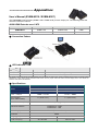
1
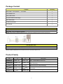
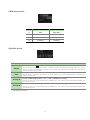
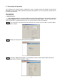
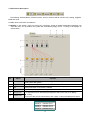
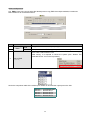
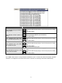
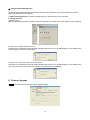
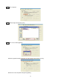
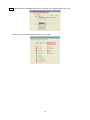
Table of Contents ---------------------- Introduction .................................................................................................... 1 Overview .................................................................................................................................... 1 Features ..................................................................................................................................... 1 Package Content ..................................................................................................................... 2 Related Products ..................................................................................................................... 2 Product Description ............................................................................................................... 3 Installation................................................................................................................................. 6 Device Connection.......................................................................................................... 6 Connection Pattern ......................................................................................................... 6 LED Indicator............................................................................................................................ 7 Operation ................................................................................................................................... 8 Push Button Control .................................................................................................. 8 IR Remote Control .................................................................................................... 11 Specifications......................................................................................................................... 13 ------------------------ Serial Configuration ............................................................................... 15 Simple Serial Connection ................................................................................................... 15 GUI over Serial ....................................................................................................................... 16 A. Installing Application ............................................................................................... 16 B. Uninstalling Application ......................................................................................... 16 C. Description & Operation ......................................................................................... 17 D. Firmware Upgrade .................................................................................................... 22 ------------------------ Appendices ................................................................................................. 25 User’s Manual (EVBM-M110 / EVBM-M107) .................................................................... 25 Please read this manual thoroughly and follow the Installation procedures to prevent any damage to the unit or any connecting device. * The final specifications are the actual product based. * Features and functions are subject to change since the manual was written. Please visit the related website to download the latest version of manual for reference. RoHS ---------------------- Introduction Overview Rextron 4K2K HDMI / VGA HDBaseTTM Transmitter transmits full uncompressed 4K2K video and HD audio over CATx cable of up to 70/100 meters. It not only supports resolution up to Full HD 1080p and 4K2K, but supports Deep Color and HD Audio formats as well. The optional Graphical User Interface (GUI) function makes control easier and more effectively. The well-designed GUI can free users from giving complex commands. What’s more fantastic is that it allows you to name and portray your source and display icons for user-friendly operation. The advanced and inexpensive all-in-one connectivity technology by using low-cost and handy CATx cables, Rextron 4K2K HDMI / VGA HDBaseTTM Transmitter is perfect for situations like hospitality (hotels, conference rooms) and digital signage (airports, shopping malls), etc. Features Transmit HDMI / VGA+audio signal over CATx cable of up to 70/100 meters Use HDBaseTTM technology Low cost standard CAT5e/6 LAN cable; advanced and inexpensive all-in-one connectivity technology HDTV, 3D HDTV compatible; HDCP compliant and Blu-ray ready Input source sequence selectable Support resolution up to Full HD (1920 x 1080) / UHD (3840 x 2160) Support Deep Color and HD Audio formats Plug-n-Play system without any drivers or software installation Ideal for hospitality (hotels, conference rooms), digital signage (airports, shopping malls), surveillance cameras, whole-home networking and point-to-point consumer applications Unique EGO MX Functions Versatile port selection functions of Priority, Auto and Switch modes User-friendly port switching via button pressing or priority setting Two priority settings to start with VGA / HDMI source for different needs Auto-Sensing function enables the system to automatically select the latest video source Exclusive EDID Functions Multi-functions for EDID setting, like EDID Copy and EDID Pre-setting, ensuring accurate output display Enable separately learn Audio and Video EDID for multimedia/ Home Theater system integration Read and store the EDID from the connecting display to the video extension Exclusive GUI Operation Functions Graphically show connection status Most commonly used menu items are duplicated as icons on the top Common icons are provided Can name and use your own images for every source and display icon Exclusive Link Port Functions Increase the extension distance up to 150 meter for Full HD 1080p Automatically save energy for increasing efficient use 1 Package Content Content Quantity 4K2K HDMI / VGA HDBaseTTM Transmitter 1 Power Adapter Set 1 CAT5 cable for test 1 CD (User’s Manual & GUI app) 1 Quick Start Guide 1 IR Remote Controller 1 Foot Pad Set 1 Optional IR Sensor Kit RJ12 Cable + RJ12 to RS232 converter* *NOTE: If users want to use RJ12 to RS-232 converter, please follow the diagram below to properly connect the pin: You may also need Receiver Unit: EVBM-110R (100M) / EVBM-107R (70M) HDMI Cable (M-to-M) 1.8m for HDMI A/V source connection NOTE: EVBM-K107R&EVBM-K110R can select source from Transmitter to Receiver unit. Product Family Pair Tx Rx EVBM-M107 EVBM-M110 EVBM-107L EVBM-110L EVBM-107R EVBM-110R EVBMN-M110 EVBMN-110L EVBMN-110R EVBMV-1371L EVBMV-1391L EVBMC-1371L EVBMC-1391L EVBM-K107R EVBM-K110R Description 70M / 100M HDMI Extender Pair HDMI Extender Pair with Bidirectional IR, Ethernet & Serial Extending 70M / 100M HDMI x 2 / VGA + Audio Transmitter with Bidirectional IR & Serial Extending 70M / 100M DisplayPort / HDMI x 2 / VGA + Audio Transmitter HDMI Receiver with Scaling Function 2 Product Description Front Panel 1 Input Port Button Source selection 2 Function Button System Configuration 3 Input Port LED Please see LED Indicator 4 Output Port Button Turn ON / OFF Output Signal 5 Output Port LED Please see LED Indicator 6 IR Sensor IR remote controller sensor Rear Panel I1 Connect to VGA + Analog stereo source Video Input Port I2 I3 Ro Remote Output Port Connect to a receiver Lo Local Output Port Connect to an HDMI display B EDID Copy Button Pair with EDID Setting Switch to copy monitor's EDID S1 EDID Setting Switch See the diagram of EDID Setting Switch S2 EGO Slide Switch See the diagram of EGO Slide Switch S3 Link Port Switch See the diagram of Link Port Switch R IR Connector C Serial Port Connect to a serial console (PC) P Power Supply Apply power to the unit Connect to an HDMI source [In] Connect to IR Receiver [Out] Connect to IR Transceiver 3 EDID Setting Switch Mode Video Audio 1 Auto Auto (Min.) 2 Auto Inventory 3 Inventory Auto (Min.) 4 Inventory Inventory EGO Slide Switch Mode Switch Auto Description Press Select button Kn to select Source-n; all monitors display Source-n NOTE: When switching from Matrix to Switch mode, all monitors display Source-1. But if there’s no source detected in Source-1, the system will automatically display the next video source (follow Priority order). System will automatically select the latest video source for display NOTE: When switching from Matrix to Auto mode, the system automatically displays the latest video source. Priority-A Priority: HDMI1(High Priority) > DP* > VGA > HDMI2(Low Priority) NOTE: If there’s no source detected in HDMI1 port, the system will automatically display the next video source. Priority-B Priority: HDMI2(High Priority) > VGA > DP* > HDMI1(Low Priority) NOTE: If there’s no source detected in HDMI2 port, the system will automatically display the next video source. * depending on model 4 Port Link Switch Mode Auto Power Saving Normal Long Reach Description Automatically save energy when source or monitor connected failure Normal operation (up to 4K2K) Extend distance from 100M to 150M (up to Full HD 1080p) 5 Installation WARNING! ● Prior to installation, ensure to power off all devices that will be connected to this system. ● Ensure that all devices you will connect are properly grounded. ● Place cables away from fluorescent lights, air conditioners and machines that are likely to generate electrical noise. ● Please allow adequate space around the unit for air circulation. Grounding To prevent any damage to the product or any connecting devices, and to improve audio/video signal quality, it is important to make sure that the extender systems are properly grounded. Device Connection 1. Use a CAT5 cable to connect to a receiver. Connect the receiver to an HDMI display. 2. Use an HDMI cable to connect the source device to the HDMI input port on the Unit. The HDMI input ports are located on the rear of the Unit. Use a HDMI cable to connect the source device to the HDMI input port and a VGA cable to connect the source device to the VGA input port on the Unit. Connect the stereo audio source to 3.5mm earphone jack (if necessary) 3. Use an HDMI cable for connection between display and the HDMI output port on the Unit (if needed). 4. Apply the proper power to the Unit; then power on all the attached sources and devices. NOTE: If users encounter no screen display in display connection, you may 1. make sure the device cables are correctly and firmly attached. 2. set your display device’s input source as HDMI. 3. check the PC BIOS configuration about the video output setting. 4. connect your computer to the HDMI Display DIRECTLY to check if the video signal gets through. 5. slide the switches to the correct positions according to your displays. 6. apply EDID Copy to your display (see EDID Setting section). Connection Pattern Type Rx Model EVBM-107R EVBM-110R EVBM-K107R EVBM-K110R 6 Function 70M / 100M HDMI Receiver HDMI Receiver with Scaling Function (Source console function ) LED Indicator Input Port LED Video OK Source Selected Emit Blue and go off 3 times Yes Yes Flash Blue once Yes No Emit Purple and go off 3 times Yes Yes Flash Purple once Yes No Emit Blue and flash Red once No Yes OFF No No Note w/o HDCP w/ HDCP Emit Blue and Flash Orange twice / Resolution Three Times Alternation (ONLY happen in Screen Shift Mode) Remote Unit LED ON / OFF CAT5 detected Status Flash Blue once ON YES Monitor Non-detected Steady Blue ON YES Monitor detected ON YES HDCP doesn’t match Flash Green once ON NO OFF OFF YES / NO Emit Blue and Flash Purple once Red twice Local Unit LED ON / OFF Status Flash Blue once ON Monitor Non-detected Steady Blue ON Monitor detected Emit Blue and Flash Purple once Red ON HDCP doesn’t match twice OFF OFF 7 Operation Push Button Control Users may select 1 from 3 and distribute to displays via push button, wireless remote and serial control. A built-in buzzer generates a high-pitched beep for a correct push button command and a short-long beep for completing a command. Otherwise, one low-pitched generates for an error, and the bad key sequence will not be forwarded to the unit. F = Function button RB = Remote button LB = Local button 1 ~ 3 = Key1, Key2, Key3 = 1. A/V Source Selection ◎ Switch-Splitter Mode (Switch, EGO-Auto, EGO-Priority) For source 1-3, just press the related push button to select the desired source. Press 1 / 2 / 3 : Select Source1 / Source 2 / Source 3 2. Turn ON/OFF Remote Output Signal Press and hold RB for 2 sec. and release after Remote Unit LED flashes Blue: Turn ON/OFF the connection of Remote Unit Press and hold LB for 2 sec. and release after Local Unit LED flashes Blue: Turn ON/OFF Local output port 3. EDID Setting In some cases display problems may occur due to incorrect EDID communication between the display monitor and the unit or inappropriate EDID data programmed by display manufactures. This function allows the system either to read the necessary EDID information from the unit or to copy EDID from EDID compliant displays. For more details and functions, please consult the following statements. 3-1. EDID Copy If the unit is insufficient for EDID of the attached displays, it is suggested to copy EDID from the displays. Before starting, slide EDID Setting Switch to the desired position. Mode Video Audio 1 Auto Auto (Min.) -- 2 Auto Inventory Copy Audio EDID 3 Inventory Auto (Min.) Copy Video EDID 4 Inventory Inventory Copy all EDID 8 Copy Remote Monitor EDID Step 1. Apply power to the unit. Step 2. Use CAT5 to connect Remote unit to Local unit and the (EDID compliant) monitor connects to the Remote Unit. Power on the monitor. Step 3. Press and hold the button “EDID COPY” around 3 sec. and release the button RIGHT AFTER the Remote LED flashes GREEN. Result. If the Remote LED returns to normal status, indicating that the EDID Copy is completed. Copy Local Monitor EDID Step 1. Apply power to the unit. Step 2. Connect the (EDID compliant) monitor to local output port “Local OUT” of the Unit and power on the monitor. Step 3. Press and hold both of the buttons “EDID COPY” around 6 sec. and release the button RIGHT AFTER the Local LED flashes GREEN. Result. If the Local LED returns to normal status, indicating that the EDID Copy is completed. Factory Default Setting (for all settings) Step 1. Apply power to the unit. Step 2. Press and hold both of the buttons “EDID COPY” around 9 sec. and release the button RIGHT AFTER the Local LED flashes BLUE. Result. If the Local LED returns to normal status, indicating that the Factory Default Setting is completed. Otherwise, the LED flashes RED indicating that: a. The monitor is not properly connected. b. The monitor is not powered on. c. EDID data of the monitor is not applicable. d. The CAT5 cable is not well-connected. 3-2. EDID Emulation After EDID Copy, you may slide EDID Setting Switch to the desired position and apply the copied EDID to the display. Mode Video Audio 1 Va). Auto Aa). Auto (Min.) 2 Va). Auto Ai). Inventory 3 Vi). Inventory Aa). Auto (Min.) 4 Vi). Inventory Ai). Inventory 9 Va). Aa). Vi). Ai). Video Auto Mixing: Audio Auto Mixing: Video Inventory: Audio Inventory: Automatically optimize all valid video outputs for minimum requirement Automatically perform the minimum audio format of all attached displays After copying Video EDID, use the copied Video EDID to the connected display After copying Audio EDID, use the copied Audio EDID to the connected display 4. EQ Adjustment To optimize video quality, users can adjust the video equalization (sharpness) for all video input ports through push button configuration. Since 8 levels for EQ adjustment are provided, the Remote Unit LED flashes BLUE to indicate level 1-4 is selected and while it flashes GREEN indicating level 5-8 selected. Tip: Double-click F → press 3 (enter EQ Adjustment mode) →press 3 (press 1~8 times based on video quality. 8 levels: Blue-level 1-4; Green-level 5-8) →press F 5. Stand-by Mode To have the system switch to stand-by mode, Press and hold both of RB & LB buttons for 3 sec and release right after the Remote and Local Unit LED flash Green. Then when the Remote and Local Unit LED flashes BLUE per 3 seconds, the system is in the stand-by mode. And just follow the same steps to wake up from stand-by mode. Tip: press RB & LB (3sec.) → Status LED flashes GREEN → release RB & LB 6. Screen Shift Mode (VGA Input ONLY) Step 1. Press two buttons ( 3 & F ) simultaneously over 2 sec. and release the buttons RIGHT AFTER L3 (VGA LED) turns to Pale Blue. Step 2. Press left button (1) or right button (2) to adjust image's position. NOTE: 1. The system will automatically retain user's last setting. 2. Max. horizontal image displacement is 50 steps. 3. The system will automatically escape from shift mode if no activity is detected within 15 seconds, or directly press the two buttons simultaneously over 2 sec. again to leave the shift mode right away. 7. Resolution Alteration Mode (VGA Input ONLY) Under some particular video resolution issue, L3 (VGA LED) will turn to emit Blue and flash Orange twice / three times when catching multiple similar video timing in Screen Shift Mode. Step 1. Enter in the Screen Shift Mode Step 2. Press the button (3) over 2 sec. Step 3. LED flashes Purple once indicating the setting working NOTE: 1. VGA LED emits Blue and flashes Orange twice meaning DVI output. It is HDMI output when the LED emits Blue and flashes Orange three times 2. The system will automatically retain user's last setting. 3. Press the button over 2 sec. again to select next available resolution or switch back to the previous resolution. 10 IR Remote Control Users can achieve the remote job with the range of 5 meters. See the following for more operation steps. NOTE: The numeric keys on the left of the controller represents each output on the rear panel (marked in black) and while the right stands for the input displays (marked in blue). For other function keys, please refer to the picture as shown on the right of this page. Please note the following descriptions: Mn (output/monitor): buttons 1 ~ 2 on the left side of remote controller Sn (input/source): buttons 1 ~ 3 on the right side of remote controller 1. A/V Source Selection ◎ Switch-Splitter Mode (Switch, EGO-Auto, EGO-Priority) For source 1-3, just press the related push button on the right side of the controller. Tip: Press Sn (right): Select Source-n 2. Turn ON/OFF Remote Output Signal To turn on or off remote output signal, you may press the output port first, and then press VIDEO. Tip: Press Mn (left) and then press VIDEO (toggle) (n=1~4) 3. EQ Adjustment To optimize video quality, users can adjust the video equalization (sharpness) for all video output ports through push button configuration. Since 8 levels for EQ adjustment are provided, the Remote Unit LED flashes GREEN to indicate level 1-4 is selected and while it flashes BLUE indicating level 5-8 selected. Press VIDEO and press 3 to enter video adjustment mode. Next, press 3 repeatedly to adjust EQ level. And lastly press VIDEO to exit the setting. Tip: VIDEO → 3 (enter this mode) → 3 (press 1~8 times based on video quality) → VIDEO 11 4. Multiple Units Application Up to 16 units can share one remote controller. In order to avoid ambiguities in receiving commands simultaneously, ID setting for each unit is strongly suggested. 4-1. ID Setting via IR Remote Controller This function is designed to name the units via front panel push buttons and remote controller. Please follow the steps as shown below. Step 1 Power OFF the unit. Step 2 Press and hold 1 & 2 on the panel of the unit. Step 3 Power ON the unit. Step 4 Release 1 & 2 RIGHT AFTER Power LED flashes red. Step 5 IMMEDIATELY (within a second or two) press one of the numbers from 1 to 10 or +10 and 1~6 on the RIGHT side of IR remote controller as the unit controller ID. For example, press the number 4 (right). This sets the unit IR remote controller ID as 4. For ID number 11~16, users may follow the step bellow. To set the unit IR remote controller ID as 15, press the number +10 and then 5 (right) on the right side of on the controller. The idle time out is 10 sec. NOTE: 1. Take Steps 1 to 5 if controller ID set-up for more than one unit is needed. 2. Each unit should have a unique control ID to avoid any confusion on receiving commands from the IR remote controller simultaneously. To reset ID, follow above Step 1 to Step 4, then Step 5 IMMEDIATELY (within a second or two) press VIDEO of IR remote controller. 4-2. ID Operation via IR Remote Controller Each unit will accept the same signal from IR remote controller whenever the units are powered up. After numbering the unit, users need to press and hold “SHIFT” and then press ID (n) on the IR remote controller first. Then, this unit will beep once. It means this unit is ready to accept the oncoming commands via the IR remote controller. Tip: SHIFT + m ( *m represents the RIGHT numeric keys) NOTE: Because all units assume their IDs are active, it’s required to press “SHIFT” + ID again to give commands to a certain unit after re-powering up. 12 Specifications Transmitter Unit Model EVBMV-1371L HDMI x 2 VGA + Analog Stereo x 1 Input HDMI x 1 RJ45 x 1 Out Source x 3 Remote x 1, Local x 1 LED Indicator Video Resolution (max.) UHD (3840 x 2160) HDMI HDMI 70M @ Full HD 100M @ Full HD (1920 x 1080) (1920 x 1080) 35M @ UHD 70M @ UHD (3840 x 2160) (3840 x 2160) VGA VGA 70M @ Full HD 70M @ Full HD (1920 x 1080) (1920 x 1080) Extension Distance EDID Configuration Switch Push Button Video Auto / Inventory Audio Port Select x 3, Function x 1 Remote x 1, Local x 1, EDID Copy x 1 Mode Configuration Link Port Configuration EVBMV-1391L Switch / Auto / Pri-A / Pri-B Auto Power Saving / Normal / Long Reach Serial Port (for control) RJ12 x 1 Power Supply DC 12V Enclosure Metal H x W x D (mm) 40 x 160 x 100 Weight (g) 645-650 13 Transmitter Unit Model EVBMC-1471L HDMI x 2 VGA + Analog Stereo x 1 DisplayPort x 1 Input HDMI x 1 RJ45 x 1 Out Source x 3 Remote x 1, Local x 1 LED Indicator Video Resolution (max.) UHD (3840 x 2160) HDMI/DisplayPort HDMI/ DisplayPort 70M @ Full HD 100M @ Full HD (1920 x 1080) (1920 x 1080) 35M @ UHD 70M @ UHD (3840 x 2160) (3840 x 2160) VGA VGA 70M @ Full HD 70M @ Full HD (1920 x 1080) (1920 x 1080) Extension Distance EDID Configuration Switch Push Button Video Auto / Inventory Audio Port Select x 3, Function x 1 Remote x 1, Local x 1, EDID Copy x 1 Mode Configuration Link Port Configuration EVBMC-1491L Switch / Auto / Pri-A / Pri-B Auto Power Saving / Normal / Long Reach Serial Port (for control) RJ12 x 1 Power Supply DC 12V Enclosure Metal H x W x D (mm) 40 x 160 x 100 Weight (g) 650-660 14 ------------------------ Serial Configuration The 4K2K HDMI / VGA HDBaseTTM Transmitter’s built-in serial interface allows users to control the unit via serial control. Please follow the installation and operation steps as shown below. If there’s no serial connector on your computer, you may use USB-to-serial adapter for connection. The configuration of controller’s serial port is shown as below. Baud Rate 38,400 bps Data Bits 8 Parity None Stop Bits 1 Flow Control I. None Simple Serial Connection The following window is an example of Windows XP HyperTerminal. Connect and power on the Unit, and then set up serial configuration, such as correct baud rate and com port. 15 II. GUI over Serial A. Installing Application The serial console (PC) running Windows 98/2000/XP/Vista/7 is required to install the appropriate software. Please follow the step-by-step instructions as listed below. All prompt screens and dialog boxes shown in this section are for Windows 98 and above. Some dialog boxes and folders may slightly different in other versions of Windows. Install the "AV Console Center” driver (Windows 98 and above) Insert the CD into the CD/DVD-ROM drive and browse: There are two ways to install the driver. a) Manually copy the file "TuApp.exe" to the Windows platform and run it directly. b) Run "Setup.exe" to automatically install the utility on the Windows platform. The "Setup.exe" will create a shortcut “AV Console Center" on Windows' desktop, and a program group "AV Console Center”. B. Uninstalling Application To uninstall the driver, it depends on the installation method you have applied. a) If you have manually installed the utility, you can just manually delete the file "TuApp.exe” from the Windows platform. b) If you have installed "Setup.exe" before, you have two ways to uninstall the application. One is that uninstall "AV Console Center" from Windows' Control Panel. The other is by clicking the icon “Uninstall” from the “AV Console Center” program group. 16 C. Description & Operation The Graphical User Interface (GUI) is designed for users to operate easier and friendlier. We divide this application into two parts—Basic Operation and Advanced Operation. For more information, please refer to the following statements. Basic Operation 1. GUI Connection After software installation, connect the DB9 RS-232 serial cable (straight type male-female) to serial port of the Switch-Splitter. And connect the other end to the serial port (COM1, COM2…) of your computer. Next, open Program files on Windows and then click “AV Console Center” to start GUI operation. Step 1. Check “COM Port” and choose the proper serial port you connect, such as COM1, and set the Baud Rate as “38400”. Step 2. A dialog box will pop out indicating device(s) detected. Step 3. Double-click “Digital Switch-Splitter” on the left block. (There are other ways to detect the device. Please refer to Toolbar Guidance / Action.) 17 2. GUI Toolbar Guidance You can see the toolbar on the upper-left corner. Both top toolbars are identical in functions. For further information, please refer to the following guidance. 2.1 File: Allow users to open or save topology files. A topology is a usually schematic description of the arrangement of a network, including its nodes and connecting lines. So it is suggested saving a topology file. 2.1 1 2 3 4 Option Open Existing Topology Save Current Topology Save Current Topology As… Exit Function Open pre-stored topology file Allow users to save current topology file in the software installed location Allow users to save current topology file in the requested location Exit the system 2.2 Actions: Detect all devices or connect the selected device. When checking Detect All Devices, it will show the dialog box below which means successfully detect the device. 2.3 View: Show or hide the (Icon) Toolbar / Status Bar (on the bottom of the window) 2.4 Tools: Select Environment to set up COM Port and Baud Rate or set up TCP/IP address for the device.. 2.5 Help: Show the software version and copyright information. 18 3. GUI Function Description The following will describe the overall functions. And four sections will be included: Info, Setting, Upgrade, EDID and Tools. 3.1 Info: Show information and features. 3.2 Setting: In this section, users can set up port connection, enable or disable audio/video separately, set scan time rate, etc. By default, the system will automatically apply source 1 routing to all displays as shown below. 3.2 Option Function Automatically apply settings. It is not suggested checking this item for it may result in loading down the system. 2 Apply To bring the settings into action. Detect and show the current setting status for users may operate the unit via front 3 Get panel push button or IR remote controller 4 EQ Adjust the video equalization (sharpness) Double-click the icon and there will be a pop-up menu. Users can change the picture 5 Source Icon (.ico file with 32x32 or 36x36 pixel) and give an alias for the source or display. ◆ Linking: 6 Display Icon* Click one of the source icons and then click “Apply” to bring the settings into action. 7 Video On Check/ uncheck the item to turn on/off the display * Here’s the comparison table of the monitor port number on GUI and the output port on the Unit. display 1 Local Output Port display 2 Remote OUT 1 display 3 Remote OUT 2 display 4 Remote OUT 3 display 5 Remote OUT 4 1 Auto apply 19 Advanced Operation 3.3 EDID: Users can not only select the desired ports to copy EDID via multiple methods, but also use built-in EDID for all connected monitors. 3.3 1 2 3 Option Make Inventory EDID EDID Method Function Copy EDID to the selected input port(s). Multiple methods of EDID copy are provided. See the diagram below. All connected monitors use the selected built-in EDID; resolution ranging from 1024 x 768 to 2048 x 1152. After saving, it is required to reboot the system (click “Reboot The Selected Device” icon on the top toolbar). Built-In EDID (optional) Here’s the comparison table of the monitor port number on GUI and the output port on the Unit. Monitor 1 Monitor 2 Monitor 3 Monitor 4 Monitor 5 Local Output Port Remote OUT 1 Remote OUT 2 Remote OUT 3 Remote OUT 4 20 Method Operation Steps Copy selected input port EDID as factory default Step 1. Check the desired input port(s) or check All input ports to select all. Step 2. Click Make EDID. Copy selected input port EDID from selected monitor (audio & video) Step 1. Check the desired input port. Step 2. Select the desired Monitor (next to Method) Step 3. Click Make EDID. Copy selected input port EDID from corresponding monitor (1 on 1) Step 1. Check the desired input port(s) or check All input ports to select all. Step 2. Click Make EDID. Copy selected input port EDID from *EDID binary file Copy selected input port as *1024 x 768 customized EDID *EDID binary file: A file that store EDID information Step 1. Check the desired input port(s) or check All input ports to select all. Step 2. Click Make EDID. Step 3. Select the desired binary file. *Customized EDID: selectable resolution ranging from 1024 x 768 to 2048 x 1152 Step 1. Check the desired input port(s) or check All input ports to select all. Step 2. Click Make EDID. 3.4 Tools: Allow users to set up Remote Controller ID. Up to 16 units can share one remote controller. Therefore, it is designed to name the units for fear of confusion on receiving commands simultaneously. 21 ◆ Changing Source/Display Icon: Double-click the source/display icon and there will be a pop-up window. Users may change the icon and name the selected source or display. 1. Name the display/source: click the corresponding icon and insert any name you want. 2. Change the icon a) Built-in Icons: The GUI application provides commonly used icons (Built-in Icons) as shown on the upside of pop-up window. b) User’s Icon - Reset the button to null As shown on the downside of pop-up window; double-click the icon (01-12) and following by one dialogue box. Click this option to set the icon as blank. c) User’s Icon - Import icon file (.ico) for this button As shown on the downside of pop-up window; double-click the icon (01-12) and following by one dialogue box. You may upload your own icon but it should be .ico file with 32x32 or 36x36 pix. D. Firmware Upgrade Step 1. Connect the device and then open “Upgrade” page 22 Step 2. Click “Program” Step 3. Select a target firmware file (.abn) Step 4. Click “Yes” to start upgrading While the upgrade is being processed, you may see the red tool bar is running. NOTE: Do not turn off power during the upgrading. 23 Step 5. If the upgrade is completed with success, it will pop up a window and then click “Yes.” Finally you may check the firmware version on “Info” page. 24 ------------------------ Appendices User’s Manual (EVBM-M110 / EVBM-M107) The Transmitter need receivers (EVBM-110R / EVBM-107R) for each output port. The following shows the receivers’ instruction manual. 4K2K HDMI Extender over CAT5 Model Tx Rx Extension Distance EVBM-M110 EVBM-110L EVBM-110R 100M EVBM-M107 EVBM-107L EVBM-107R 70M ◆ Connection Pattern ◆ LED Indicator Status No video source or monitor connected Flashing blue & green Flashing blue & red LED Unit Tx Rx Power on Green Red Link OK Blue Blue The quality of the output signal will depend largely upon the quality of video source, cable, and display device used. Low-quality cables degrade the output signal causing elevated noise levels. Use the proper cable and make sure the display device can handle the resolution and refresh rate selected. ◆ Specifications Transmitter Unit Receiver Unit EVBM-110L EVBM-110R EVBM-107L EVBM-107R Input → Output HDMI → RJ-45 RJ-45 → HDMI LED Indicator (Link / Video status) x 1 (Dual Color) x 1 (Dual Color) Model Video Resolution (max.) Full HD (1080p@60Hz) Extension Distance EVBM-M110: 100M EVBM-M107: 70M Power Supply DC 12V (Phantom Power) Enclosure Weight (gram) H x W x D (mm) Metal 120 195 22 x 52 x 80 25 x 67 x 80 25 Limited Warranty IN NO EVENT SHALL THE DIRECT VENDOR'S LIABILITY FOR DIRECT OR INDIRECT, SPECIAL, INCIDENTIAL OR CONSEQUENTIAL DAMAGES, LOSS OF PROFIT, LOSS OF BUSINESS, OR FINANCIAL LOSS WHICH MAY BE CAUSED BY THE USE OF THE PRODUCT EXCEEDS THE PRICE PAID FOR THE PRODUCT. The direct vendor makes no warranty or representation, expressed or implied with respect to the contents or use of this documentation, and especially disclaims its quality, performance, merchantability, or fitness for any particular purpose. The direct vendor also reserves the right to revise or update the product or documentation without obligation to notify any user of such revisions or updates. For further information, please contact your direct vendor. All the brand names and registered trademarks are the property of their respective owners. FFP-TLS214Z-000 Made in Taiwan 26