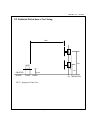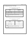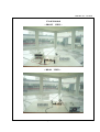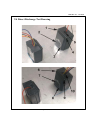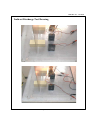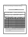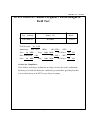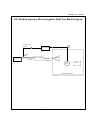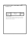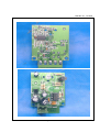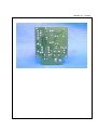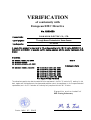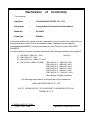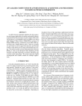
1
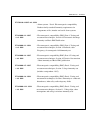
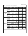
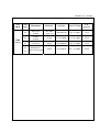
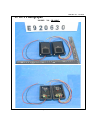
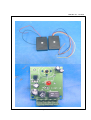
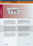
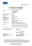
REPORT NO. : E920630
EMC TEST REPORT
According to
1) EN 55022: 1998+A1: 2000
2) EN 61000-3-2:2000
3) EN 61000-3-3: 1995+A1: 2001
4) EN 50130-4:1995+A1:1998
EN 61000-4-2: 1995+A2: 2001 / EN 61000-4-3: 1996+A2: 2001
EN 61000-4-4: 1995+A2: 2001 / EN61000-4-5: 1995+A1: 2001
EN 61000-4-6: 1996+A1: 2001 / EN 61000-4-11: 1994+A1: 2001
Main Supply Voltage Variations
Κ Through Beam Photoelectric Beam Sensor
Κ IR-3000G
EQUIPMENT
MODEL NO.
Κ YUAN HSUN ELECTRIC CO., LTD.
APPLICANT
NO. 57, CHUNG HE RD., ZUO-YING DIST., KAOHSIUNG
CITY 813, TAIWAN, R. O. C.
Test Engineer
Κ
SIMON LIU
Checked
Κ
HADES HUANG
Κ
NOV.
Issued
by
Date
07,
2003
ΘThe test report shall not be reproduced except in full, without the written approval of the
laboratory.
ΘThe report can’t be used by the client to claim product endorsement by PEP Testing
Laboratory.
ΘThis report is only for the equipment which described in page 7.
Page 1 of 42
REPORT NO. : E920630
TABLE
1.
OF
CONTENTS
4
General
1.1 General Information
1.2 Place of Measurement
1.3 Test standard
2. Product Information/Product Technical Judgement
7
3. EUT Description and Test Conclusion
8
4.
Modification(s)
9
5.
Test Software Used
9
6.
Support Equipment Used
10
7.
EN 55022 Conducted Disturbance Test
11
8.
EN 55022 Radiated Disturbance Test
8.1 Test Description
8.2 Test Setup
12
8.3 Test Limits
8.4 Test Setup photos
8.5 Test Data
9.
EN
9.1
9.2
9.3
9.4
9.5
61000-4-2 Electrostatic Discharge Test
Test Description
Test Setup
Test Limits
Discharge Drawing
Test Data
Page 2 of 42
21
REPORT NO. : E920630
10.
EN 61000-4-3 Radio-Frequency Electromagnetic Field Test
10.1 Test Description
10.2 Test Block Diagram
10.3 Test Limits
10.4 Test Setup Photo
29
11.
EN 50130-4 Clause 7 Main Supply Voltage Variations Test
11.1 Tests Description
35
12.
The List of Test Instruments
37
13.
EUT Photographs
39
Page 3 of 42
REPORT NO. : E920630
1. General
1.1 General Information :
Applicant :
YUAN HSUN ELECTRIC CO., LTD.
NO. 57, CHUNG HE RD., ZUO-YING DIST., KAOHSIUNG
CITY 813, TAIWAN, R. O. C.
Manufacturer :
YUAN HSUN ELECTRIC CO., LTD.
NO. 57, CHUNG HE RD., ZUO-YING DIST., KAOHSIUNG
CITY 813, TAIWAN, R. O. C.
Measurement Procedure :
EN 55022 & EN 50130-4
1.2 Place of Measurement
PEP TESTING LABORATORY
12-3Fl, No. 27-1, Lane 169, Kang-Ning St., Hsi-Chih,
Taipei Hsien, Taiwan, R. O. C.
TEL : 8862-26922097 FAX : 8862-26956236
NVLAP LAB CODE 200097-0
FCC Registration No. : 90868
Nemko Aut. No. : ELA133
BSMI Aut. No. : SL2-IN-E-11,SL2-A1-E-11
VCCI Registration No. : C-493/R-477
Page 4 of 42
REPORT NO. : E920630
1.3 Test standard
Tested for compliance with :
EN 55022:1998
+A1: 2000
- Information Technology Equipment – Radio disturbance
characteristics - Limits and methods of measurement
EN 61000-3-2: 2000
- Electromagnetic compatibility (EMC) Part 3-2: Limits –
Limits for harmonic current emissions (equipment input
Current up to and including 16A per phase
EN 61000-3-3: 1995
+A1: 2001
- Electromagnetic compatibility (EMC) Part 3-2: Limits –
Limitation of voltage fluctuations and flicker in low-voltage
supply systems for equipment with rated current up to 16A
Page 5 of 42
REPORT NO. : E920630
EN 50130-4:1995+A1: 1998
- Alarm systems – Part 4. Electromagnetic compatibility
Product family standard: Immunity requirements for
components of fire, intruder and social alarm systems
EN 61000-4-2: 1995
+A2: 2001
- Electromagnetic compatibility (EMC) Part 4: Testing and
measurement techniques, Section 2: Electrostatic discharge
immunity test Basic EMC Publication
EN 61000-4-3: 1996
+A2: 2001
- Electromagnetic compatibility (EMC) Part 4: Testing and
measurement techniques, Section 3: Radiated, radioFrequency, electromagnetic field immunity test
EN 61000-4-4: 1995
+A2: 2001
- Electromagnetic compatibility (EMC) Part 4: Testing and
measurement techniques, Section 4: Electrical fast transient
/ Burst immunity test Basic EMC publication
EN 61000-4-5: 1995
+A1: 2001
- Electromagnetic compatibility (EMC) Part 4: Testing and
measurement techniques, Section 5: Surge immunity test
(includes corrigendum: 1995)
EN 61000-4-6: 1996
+A1: 2001
- Electromagnetic compatibility (EMC) Part 4: Testing and
measurement techniques, Section 6: Immunity to conducted
disturbances, induced by radio-frequency fields
EN 61000-4-11: 1994
+A1: 2001
- Electromagnetic compatibility (EMC) Part 4: Testing and
measurement techniques, Section 11: Voltage dips, short
interruptions and voltage variations immunity tests
Page 6 of 42
REPORT NO. : E920630
2. Product Information
a.
EUT Name:
b.
Model No.
Through Beam Photoelectric Beam Sensor
c.
Κ
CPU TypeΚ
d.
CPU Frequency
e.
Crystal/Oscillator(s)
f.
Chassis Used
g.
Port/Connector(s)
h.
Power Rating
Direct ----- DC 24V
i.
Condition of the EUT :
ϭ Prototype Sample Engineering Sample
ϭ Production Sample
j.
Test Item Receipt Date :
NOV.
IR-3000G
N/A
Κ
Κ
Κ
N/A
Κ
N/A
ABS
Κ
ʳ
N/A
03,
2003
2a. Product Technical Judgement
Based on the major electrical and mechanical constrictions of the EUT, We hereby declare
that the subject product does fully comply with the following EMC requirements
without additional test required :
1) EN 61000-3-2: 2000
2) EN 61000-3-3: 1995+A1: 2001
3) EN 61000-4-4: 1995+A2: 2001
4) EN 61000-4-5: 1995+A1: 2001
5) EN 61000-4-6: 1996+A1: 2001
6) EN 61000-4-11: 1994+A1: 2001
These test standards will be applicable to both of PEP EMC verification and declaration
of conformity for technical reference.
Page 7 of 42
REPORT NO. : E920630
3. EUT Description and Test Conclusion
The equipment under test (EUT) is Through Beam Photoelectric Beam Sensor model
IR-3000G. The EUT that consists of a transmitter and a receiver is used for the applications at
place such as gate or garage door, overhead doors, barrier, door entrance, alarm system or
parking lot. The sensing range between EUT transmitter and receiver is 30 meters. DC
10~24V from any power source is required to operate EUT. For more detail specification
about EUT, please refer to the user’s manual.
Test method: According to the major function designed, the placement of EUT transmitter
and receiver was arranged for test and the test was respectively carried out on
the following operational condition.
(A) Tx On: a) Connect NA terminal of EUT receiver and Line of AC source;
b) Connect C terminal of EUT receiver and Neutral of AC source
via a lamp load;
c) Respectively supply EUT transmitter and receiver DC 24V from
DC power source.
(B) Tx Off: a) Connect NC terminal of EUT receiver and Line of AC source;
b) Connect C terminal of EUT receiver and Neutral of AC source
via a lamp load;
c) Respectively supply EUT transmitter and receiver DC 24V from
DC power source.
The worst-case test result of each test mode was recorded and provided in this
report.
Conducted emission test:
N/A
Radiated emission test:
The maximum readings were found by varying the height of antenna and then rotating the
turntable. Both polarization of antenna, horizontal and vertical, are measured. The effect of
varying the position of the interface cables has been investigated to find the configuration that
produces maximum emission.
The highest emissions were also analyzed in details by operating the spectrum analyzer in fixed
tuned quasi-peak mode to determine the precise amplitude of the emissions.
In addition, the following test standards are applicable for related tests being carried out on
the same EUT configuration and operational condition kept during radiated emission test and
conducted emission test:
EN 61000-4-2, EN 61000-4-3, EN 61000-4-11 and Main Supply Voltage Variations.
Page 8 of 42
REPORT NO. : E920630
4. Modification(s):
N/A
5. Test Software Used
N/A
Page 9 of 42
REPORT NO. : E920630
6. Support Equipment Used
1. DC Power Supply
Κ
Κ
Κ
Manufacturer ABM
Model Number 9306D
Power Cord Non-Shielded, Detachable, 1m
2. The Overload of Lamp
Page 10 of 42
REPORT NO. : E920630
7. EN 55022 Conducted Disturbance Test
Test Standard
EN 55022
Model No.
Result
IR-3000G
N/A
Page 11 of 42
REPORT NO. : E920630
8. EN 55022 Radiated Disturbance Test
Test Standard
EN 55022
Model No.
Result
IR-3000G
Passed
8.1 Radiated Disturbance Test Description
Preliminary measurements were made indoors chamber at 3 meter using broadband
antennas, broadband amplifier, and spectrum analyzer to determine the frequency
producing the maximum EME. Appropriate precaution was taken to ensure that all
EME from the EUT were maximized and investigated. The system configuration,
clock speed, mode of operation or video resolution, turntable azimuth with respect to
the antenna were noted for each frequency found. The spectrum was scanned from 30
to 1000 MHz using logbicon antenna. Above 1GHz, linearly polarized double ridge
horn antenna were used.
Final measurements were made outdoors at 10-meter test range using biconical,
dipole antenna or horn antenna. The test equipment was placed on a wooden bench
situated on a 1.5x1 meter area adjacent to the measurement area. Sufficient time for
the EUT, support equipment, and test equipment was allowed in order for them to
warm up to their normal operating condition. Each frequency found during pre-scan
measurements was re-examined and investigated using Quasi-Peak Adapter. The
detector function was set to CISPR quasi-peak mode and the bandwidth of the
receiver was set to 120kHz.
The half-wave dipole antenna was tuned to the frequency found during preliminary
radiated measurements. The EUT, support equipment and interconnecting cables
were re-configured to the set-up producing the maximum emission for the frequency
and were placed on top of a 0.8-meter high non-metallic 1 x 1.5 meter table. The
EUT, support equipment, and interconnecting cables were re-arranged and
manipulated to maximize each EME emission. The turntable containing the system
was rotated; the antenna height was varied 1 to 4 meters and stopped at the azimuth
or height producing the maximum emission.
Page 12 of 42
REPORT NO. : E920630
8.2 Radiated Disturbance Test Setup
10m
4m
(EUT)
1m
GROUND
PLANE
0.8m
TURN TABLE
TO
EUT = Equipment Under Test
Page 13 of 42
RECEIVER
REPORT NO. : E920630
8.3 Radiated Disturbance Test Limits
Limits for radiated disturbance of Class A ITE at
a measuring distance of 10 m
Frequency
MHz
Field Strength
dB(ӴV/m)
30
to
230
40
230
to
1 000
47
NOTES
1 The lower limit shall apply at the transition frequency.
2 Additional provisions may be required for cases where interference
occurs.
Limits for radiated disturbance of Class B ITE at
a measuring distance of 10 m
Frequency
MHz
Field Strength
dB(ӴV/m)
30
to
230
30
230
to
1 000
37
NOTES
1 The lower limit shall apply at the transition frequency.
2 Additional provisions may be required for cases where interference
occurs.
Page 14 of 42
REPORT NO. : E920630
8.4 Radiated Disturbance Test Setup Photos
TX ON MODE
< FRONT VIEW >
< REAR VIEW >
Page 15 of 42
REPORT NO. : E920630
TX OFF MODE
< FRONT VIEW >
< REAR VIEW >
Page 16 of 42
REPORT NO. : E920630
8.5 Radiated Disturbance Test Data
Model No.
Frequency range
Frequency range
Temperature
Memo
: IR-3000G
: 30MHz to 1GHz
: above 1GHz
: 26o C
: TX ON MODE
Antenna polarization :
Over
Freq.
(MHz)
Level
Limit
(dBuV/m) (dB)
Limit
Detector
Detector
Humidity
HORIZONTAL ;
Read
Line
Level
(dBuV/m) (dBuV)
: Quasi-Peak Value
: Quasi-Peak/Average Value
: 56 %
Test distance :
Antenna Cable
Preamp
Factor
(dB)
Factor
(dB)
Loss
(dB)
10m ;
Azimuth
(̓angle)
Antenna
High(m)
!
!!!!49/533!!!2:/77!!.21/45!!41/11!!!35/59!!25/64!!!1/72!!!2:/:7!!!228/1!!!5/1!!
!!!33:/675!!!28/72!!.23/4:!!41/11!!!37/37!!!:/48!!!2/63!!!2:/65!!!252/1!!!5/1!!!
!!!353/53:!!!33/95!!.25/27!!48/11!!!41/38!!21/59!!!2/68!!!2:/59!!!!:4/1!!!5/1!!!
!!!697/:26!!!36/55!!.22/67!!48/11!!!32/53!!31/35!!!3/6:!!!29/92!!!!96/1!!!4/6!!
!!!858/465!!!38/:7!!.!:/15!!48/11!!!31/12!!35/45!!!3/91!!!2:/2:!!!328/1!!!4/6!!
!!!914/466!!!39/51!!.!9/71!!48/11!!!32/67!!33/79!!!4/2:!!!2:/14!!!36:/1!!!4/6
Note :
1.
2.
Level = Read Level + Antenna Factor + Cable Loss – Preamp Factor
Over Limit = Level – Limit Line
Page 17 of 42
REPORT NO. : E920630
Model No.
Frequency range
Frequency range
Temperature
Memo
: IR-3000G
: 30MHz to 1GHz
: above 1GHz
: 26 o C
: TX ON MODE
Antenna polarization :
Over
Freq.
(MHz)
Level
Limit
(dBuV/m) (dB)
Limit
Detector
Detector
Humidity
VERTICAL ;
Read
: Quasi-Peak Value
: Quasi-Peak/Average Value
: 56 %
Test distance :
Antenna Cable
Line
Level
Factor
(dBuV/m) (dBuV) (dB)
Loss
(dB)
10m ;
Preamp
Factor
(dB)
Azimuth
(̓angle)
Antenna
High(m)
!
!!!!57/477!!!33/49!!!.!8/73!!41/11!!!41/73!!22/2:!!!1/68!!!31/11!!332/1!!!2/1!!
!!!22:/:46!!!31/28!!!.!:/94!!41/11!!!44/13!!!7/26!!!1/:1!!!2:/:1!!34:/1!!!2/1!!!
!!!285/357!!!29/98!!!.22/24!!41/11!!!36/94!!22/45!!!2/41!!!2:/71!!215/1!!!2/1!!!!
!!!553/295!!!36/96!!!.22/26!!48/11!!!37/83!!27/67!!!3/39!!!2:/82!!283/1!!!2/6!!!!
!!!697/:69!!!37/18!!!.21/:4!!48/11!!!33/16!!31/35!!!3/6:!!!29/92!!413/1!!!2/6!!!!
!!!819/946!!!38/83!!!.!:/39!!48/11!!!33/83!!32/67!!!3/83!!!2:/39!!26:/1!!!2/6
Note :
1.
2.
Level = Read Level + Antenna Factor + Cable Loss – Preamp Factor
Over Limit = Level – Limit Line
Page 18 of 42
REPORT NO. : E920630
Model No.
Frequency range
Frequency range
Temperature
Memo
: IR-3000G
: 30MHz to 1GHz
: above 1GHz
: 26o C
: TX OFF MODE
Antenna polarization :
Over
Freq.
(MHz)
Level
Limit
(dBuV/m) (dB)
Limit
Detector
Detector
Humidity
HORIZONTAL ;
Read
Line
Level
(dBuV/m) (dBuV)
: Quasi-Peak Value
: Quasi-Peak/Average Value
: 56 %
Test distance :
Antenna Cable
Preamp
Factor
(dB)
Factor
(dB)
Loss
(dB)
10m ;
Azimuth
(̓angle)
Antenna
High(m)
!
!!!!49/544!!31/::!!!.!:/12!!41/11!!!36/92!!!25/64!!1/72!!!2:/:7!!!226/1!!!5/1!!!
!!!22:/:52!!2:/7:!!!.21/42!!41/11!!!43/65!!!!7/26!!1/:1!!!2:/:1!!!317/1!!!5/1!!!
!!!33:/676!!27/97!!!.24/25!!41/11!!!36/62!!!!:/48!!2/63!!!2:/65!!!248/1!!!5/1!!!
!!!5::/6:4!!36/63!!!.22/59!!48/11!!!34/1:!!!29/94!!3/61!!!29/:1!!!27:/1!!!4/6!!!!
!!!697/:33!!37/16!!!.21/:6!!48/11!!!33/14!!!31/35!!3/6:!!!29/92!!!!99/1!!!4/6!!!
!!!858/452!!36/49!!!.22/73!!48/11!!!28/54!!!35/45!!3/91!!!2:/2:!!!418/1!!!4/6
Note :
1. Level = Read Level + Antenna Factor + Cable Loss – Preamp Factor
2. Over Limit = Level – Limit Line
Page 19 of 42
REPORT NO. : E920630
Model No.
Frequency range
Frequency range
Temperature
Memo
: IR-3000G
: 30MHz to 1GHz
: above 1GHz
: 26 o C
: TX OFF MODE
Antenna polarization :
Over
Freq.
(MHz)
Level
Limit
(dBuV/m) (dB)
Limit
Detector
Detector
Humidity
VERTICAL ;
Read
: Quasi-Peak Value
: Quasi-Peak/Average Value
: 56 %
Test distance :
Antenna Cable
Line
Level
Factor
(dBuV/m) (dBuV) (dB)
Loss
(dB)
10m ;
Preamp
Factor
(dB)
Azimuth
(̓angle)
Antenna
High(m)
!
!!!!49/497!!2:/95!!!.21/27!!!41/11!!!35/71!!25/6:!!!1/72!!!2:/:7!!!29:/1!!!2/1!!!!
!!!!57/541!!31/75!!!.!:/47!!!41/11!!!39/:6!!22/23!!!1/68!!!31/11!!!328/1!!!2/1!!!!
!!!22:/:19!!32/87!!!.!9/35!!!41/11!!!45/72!!!7/26!!!1/:1!!!2:/:1!!!345/1!!!2/1!!!
!!!4:4/983!!36/54!!!.22/68!!!48/11!!!37/48!!27/64!!!3/1:!!!2:/67!!!!:4/1!!!2/6!
!!!553/283!!37/25!!!.21/97!!!48/11!!!38/12!!27/67!!!3/39!!!2:/82!!!27:/1!!!2/6!!
!!!94:/831!!38/:9!!!.!:/13!!!48/11!!!32/44!!33/84!!!4/23!!!2:/31!!!286/1!!!2/6
Note :
1. Level = Read Level + Antenna Factor + Cable Loss – Preamp Factor
2. Over Limit = Level – Limit Line
Page 20 of 42
REPORT NO. : E920630
9. EN 61000-4-2 Electrostatic Discharge Test
Test standard
Model No.
EN 61000-4-2
IR-3000G
Result
Passed
Criteria for Compliance:
There shall be no damage, malfunction or change of status due to the conditioning.
Flickering of an indicator during the application of the discharges is permissible,
providing that there is no residual change in the EUT or any change in outputs.
Page 21 of 42
REPORT NO. : E920630
9.1 Electrostatic Discharge Test Description
This standard relates to equipment, systems, sub-systems and peripherals which may be
involved in static electricity discharges owing to environmental and installation conditions.
such as low relative humidity, use of low-conductivity (artificial-fibre) carpets, vinyl garments,
etc., which may exist in allocations classified in standards relevant to electrical and electronic
equipment.
The test set-up shall consist of a wooden able, 0.8 m high standing on the ground reference
plane. A horizontal coupling plane(HCP), 1.6 m x 0.8 m, shall be placed on the table. The
EUT and cables shall be isolated from the coupling plane by an insulating support 0.5 mm
thick .
A ground reference plane shall be provided on floor of the laboratory. It shall be metallic
sheet of 0.25 mm minimum thickness. The minimum size of the reference plane is 1 m, the
exact size depending on the dimensions of the EUT .
It shall project beyond the EUT or coupling plane by at least 0.5 m on all sides. and shall be
connected to the protective grounding system.
In order to minimize the impact of environmental parameters on test results, the tests shall be
carried out in climatic and electromagnetic reference conditions.
Climatic conditions
- ambient temperature:
15 кʳ to 35к;
- relative humidity:
30 % to 60%
- atmospheric pressure:
86 KPa (860 mbar) to 106 KPa (1 060 mbar).
NOTE – Any other values are specified in the product specification.
Electromagnetic conditions
The electromagnetic environment of the laboratory shall not influence the test results.
Page 22 of 42
REPORT NO. : E920630
9.2 Electrostatic Discharge Test Setup
- Example of test set-up for table-top equipment,
laboratory tests
Page 23 of 42
REPORT NO. : E920630
9.3 Electrostatic Discharge Test Limits
Test voltages1):
Air discharges
(kV)
2; 4 & 8
Contact discharges
(kV)
2; 4 & 6
Polarity
+&-
Number of discharges per point for each voltage and polarity 10
Interval between discharges
(s)
1)
The test voltages specified are the open-circuit voltages.
The test voltages for the lower severity levels are included
because all the lower severity levels must also be satisfied.
Page 24 of 42
=1
REPORT NO. : E920630
9.4 Direct Discharge Test Drawing
Page 25 of 42
REPORT NO. : E920630
Indirect Discharge Test Drawing
Page 26 of 42
REPORT NO. : E920630
9.5 Electrostatic Discharge Test Data(Direct Discharge)
Model
No. :
Test
IR-3000G
Item : Direct Discharge
Temperature :
Storage
к
27
Capacitor
:
Discharge Rate
Instrument : NoiseKen ESS-100L
Relative Humidity :
150 pf
42 %RH
Discharge Resistor : 330 Ohm
: < 1 / Sec
Contact Discharge
Air Discharge
2 KV
4 KV
6 KV
8 KV
2 KV
4 KV
6 KV
8 KV
+
-
+
-
+
-
+
-
+
-
+
-
+
-
+
-
1
/
/
/
/
/
/
/
/
P
P
P
P
P
P
P
P
2
/
/
/
/
/
/
/
/
P
P
P
P
P
P
P
P
3
/
/
/
/
/
/
/
/
P
P
P
P
P
P
P
P
4
/
/
/
/
/
/
/
/
P
P
P
P
P
P
P
P
5
/
/
/
/
/
/
/
/
P
P
P
P
P
P
P
P
6
/
/
/
/
/
/
/
/
P
P
P
P
P
P
P
P
7
/
/
/
/
/
/
/
/
P
P
P
P
P
P
P
P
8
/
/
/
/
/
/
/
/
P
P
P
P
P
P
P
P
9
/
/
/
/
/
/
/
/
P
P
P
P
P
P
P
P
10
/
/
/
/
/
/
/
/
P
P
P
P
P
P
P
P
1.
2.
“
“
P
/
” - - - - means the EUT function is correct during the test .
” - - - - no test.
Page 27 of 42
REPORT NO. : E920630
Electrostatic Discharge Test Data(Indirect Discharge)
Model
No. :
Test
IR-3000G
Item : Indirect Discharge
Temperature :
Storage
к
27
Capacitor
:
Discharge Rate
Instrument : NoiseKen ESS-100L
Relative Humidity :
150 pf
42 %RH
Discharge Resistor : 330 Ohm
: < 1 / Sec
Contact Discharge
Air Discharge
2 KV
4 KV
6 KV
8 KV
2 KV
4 KV
8 KV
15 KV
+
-
+
-
+
-
+
-
+
-
+
-
+
-
+
-
1
P
P
P
P
P
P
/
/
/
/
/
/
/
/
/
/
2
P
P
P
P
P
P
/
/
/
/
/
/
/
/
/
/
3
P
P
P
P
P
P
/
/
/
/
/
/
/
/
/
/
4
P
P
P
P
P
P
/
/
/
/
/
/
/
/
/
/
5
/
/
/
/
/
/
/
/
/
/
/
/
/
/
/
/
6
/
/
/
/
/
/
/
/
/
/
/
/
/
/
/
/
7
/
/
/
/
/
/
/
/
/
/
/
/
/
/
/
/
8
/
/
/
/
/
/
/
/
/
/
/
/
/
/
/
/
9
/
/
/
/
/
/
/
/
/
/
/
/
/
/
/
/
10
/
/
/
/
/
/
/
/
/
/
/
/
/
/
/
/
1.
2.
“
“
P
/
” - - - - means the EUT function is correct during the test .
” - - - - no test.
Page 28 of 42
REPORT NO. : E920630
10. EN 61000-4-3 Radio-Frequency Electromagnetic
Field Test
Test
standard
Model
EN 61000-4-3
Field Strength : 10
Passed
V/M ,
80 MHz ,
1KHz .
Stop :
Pulse modulation: 1 Hz
Start :
Result
IR-3000G
Modulation : AM 80 % ,
Start :
No.
80 MHz ,
ON ( YES ) .
1000 MHz .
DC Power :
ON ( YES ) .
Stop :
1000 MHz .
OFF (
)
24
OFF (
DC Power :
Vdc
)
24
Vdc
Criteria for Compliance:
There shall be no damage, malfunction or change of status due to the conditioning.
Flickering of an indicator during the conditioning is permissible, providing that there
is no residual change in the EUT or any change in outputs.
Page 29 of 42
REPORT NO. : E920630
10.1 Radio-Frequency Electromagnetic Field Test Description
Most electronic equipment is, in some manner, affected by electromagnetic radiation.
This radiation is frequently generated by such sources as the small hand-held radio
transceivers that are used by operating, maintenance and security personnel, fixed-station
radio and television transmitters, vehicle radio transmitters, and various industrial
electromagnetic sources.
In addition to electromagnetic energy deliberately generated, there is also spurious radiation
caused by devices such as welders, thyristors, fluorescent lights, switches operating inductive
loads, etc. For the most part, this interference manifests itself as conducted electrical
interference and, as such, is dealt with in other parts of this standard. Methods employed to
prevent effects from electromagnetic fields will normally also reduce the effects from these
sources.
The electromagnetic environment is determined by the strength of the electromagnetic field
(field strength in volts per metre). The field strength is not easily measured without
sophisticated instrumentation nor is it easily calculated by classical equations and formulae
because of the effect of surrounding structures or the proximity of other equipment that will
distort and/or reflect the electromagnetic waves.
All testing of equipment shall be performed in a configuration as close as possible to the
installed case. Wiring shall be consistent with the manufacturer’s recommended procedures,
and the equipment shall be in its housing with all covers and access panels in place, unless
otherwise stated.
If the equipment is designed to be mounted in a panel, rack or cabinet, it shall be tested in this
configuration.
Page 30 of 42
REPORT NO. : E920630
10.2 Radio-Frequency Electromagnetic Field Test Block Diagram
Field Leveling
Signal
Fiber
Optic
Cable
Field Monitor
Detector
Input
RF Source
Power Amplifier
RF Input
Bulkhead
Feedthrough
Antenna
Field
Probe
Anechoic Chamber
Page 31 of 42
EUT
REPORT NO. : E920630
10.3 Radio-Frequency Electromagnetic Field Test Limits
Frequency range
Field strength1)
(MHz)
80 to 1000
(V/m)
10
Modulation:
Amplitude modulation
Pulse modulation
1)
80%, 1 kHz, sinusoidal
1 Hz (0.5 s ON: 0.5 s OFF)
The field strength quoted is the RMS value for the continuous wave, before modulation.
Page 32 of 42
REPORT NO. : E920630
10.4 Radio-Frequency Electromagnetic Field Test Setup Photo
TX ON MODE
< FRONT VIEW >
Page 33 of 42
REPORT NO. : E920630
TX OFF MODE
< FRONT VIEW >
Page 34 of 42
REPORT NO. : E920630
11. EN 50130-4 Clause 7 Mains Supply Voltage
Variations Test
Test
standard
EN 50130-4
Clause 7
Model No.
Result
IR-3000G
Passed
Criteria for Compliance:
There shall be no damage, malfunction or change of status due to the different
supply voltage conditions. The EUT shall meet the acceptance criteria for the
functional test, during the conditioning.
Page 35 of 42
REPORT NO. : E920630
11.1 EN 50130-4 Clause 7 Mains Supply Voltage Variations Tests
Description
To demonstrate the ability of the equipment to function correctly over the anticipated range
of mains supply voltage conditions.
Subject the specimen to each of the power supply conditions, indicated in table 1, until
temperature stability is reached:
Table 1
Supply voltage max
(Umax)
Unom + 10%
Supply voltage min
(Umin)
Unom – 15%
Unom = Nominal mains voltage. Where provision is made to
Adapt the equipment to suit a number of nominal supply voltages
(e.g. by transformer tap changing), the above conditioning
severity shall be applied for each nominal voltage, with the
equipment suitably adapted. For equipment which is claimed to
be suitable for a range of nominal mains voltages(e.g.220/240 V)
without adaptation, Umax = (Maximum Unom ) + 10%,and Umin =
(Minimum Unom) – 15%. In any case the range of Unom must
include the European nominal mains voltage of 230 V.
Page 36 of 42
REPORT NO. : E920630
12. The List of Test Instruments
Test Mode
Instrument
R&S
Receiver
Rolf Heine
LISN
R&S
Conduction
LISN
( No.1)
Spectrum
Analyzer
RF Cable
Schaffner
ISN
R&S
Receiver
Schaffner
Pre-amplifier
Radiation
(OP No.1)
Serial No.
ESHS10
830223/008
May 22, 2004
1Year
NNB-4/63TL
98008
May 01, 2004
1Year
ESH3-Z5
844982/039
Aug. 06, 2004
1Year
R3261A
91720076
June 08, 2004
1Year
Rg400
N/A
May 12, 2004
1Year
T411
N/A
June 29, 2004
1Year
ESVS30
863342/012
May 22, 2004
1Year
CPA9232
1028
May 20, 2004
1Year
10095
May 21, 2004
2Year
June 26, 2006
3Year
COM-Power
AH-118
Horn Ant.
(1GHz~18GHz)
Schwarzbeck
Next Cal. Date Cal. Interval
Model No.
VHAP
970 + 971
(30MHz~1GHz)
953 + 954
SMY01
841104/037
Apr. 29, 2004
2Year
RF Cable
No. 1
N/A
May 11, 2004
1Year
EMCO
3142B
Antenna
(26MHz~2GHz)
9904-1370
Aug. 24, 2004
1Year
Precision Dipole
Ant
R &S Signal
Generator
Page 37 of 42
REPORT NO. : E920630
Test
Mode
Test
item
Instrument
Model No.
4-2
ESD Test
System
ESS-100L
Next Cal. Date
Cal.
Interval
4099C01970
July 14, 2004
1Year
(A)TC-815D
4-3
Comtest
G-Strip
G-320
CC112-0008
Oct. 01, 2005
2Year
4-3
HP Signal
Generator
8648A
3619U00426
Sep. 14, 2004
1Year
HP Harmonic/
Flicker Test System
6842A
3531A-00141
Dec. 19, 2004
2Year
EMS
(NO.1)
Serial No.
3-2
3-3
Page 38 of 42
REPORT NO. : E920630
13. EUT Photographs
MODEL
NO. : IR-3000G
Page 39 of 42
REPORT NO. : E920630
Page 40 of 42
REPORT NO. : E920630
Page 41 of 42
REPORT NO. : E920630
Page 42 of 42
VERIFICATION
of conformity with
European EMC Directive
No. E920630
Document holder:
YUAN HSUN ELECTRIC CO., LTD.
Type of equipment:
Through Beam Photoelectric Beam Sensor
Type designation:
IR-3000G
A sample of the equipment has been tested for CE-marking according to the EMC Directive, 89/336/EEC. &
92/31/EEC & 93/68/EEC Standard(s) used for showing compliance with the essential requirements of the
directive:
Standard(s):
EN 55022 : 1998+A1: 2000
EN 61000-3-2:2000
EN 61000-3-3:1995+A1: 2001
EN 50130-4 :1995+A1:1998
Class B
Performance Criterion
EN 61000-4-2: 1995+A2: 2001
EN 61000-4-3: 1996+A2: 2001
EN 61000-4-4: 1995+A2: 2001
EN 61000-4-5: 1995+A1: 2001
EN 61000-4-6: 1996+A1: 2001
EN 61000-4-11: 1994+A1: 2001
Main Supply Voltage Variations
The referred test report(s) show that the product fulfills the requirements in the EMC Directive for CE marking. On this
basis, together with the manufacturer’s own documented production control, the manufacturer (or his European authorized
representative) can in his EC Declaration of Conformity verify compliance with the EMC Directive.
Signed for and on behalf of
PEP Testing Laboratory
Date: NOV. 07, 2003
M. Y. Tsui / President
Declaration
of
Conformity
The following
Applicant
:
YUAN HSUN ELECTRIC CO., LTD.
Equipment
:
Through Beam Photoelectric Beam Sensor
Model No.
:
IR-3000G
Report No.
:
E920630
is herewith confirmed to comply with the requirements set out in the Council Directive on
the Approximation of the Laws of the Member States relating to Electromagnetic
Compatibility(89/336/EEC) and the amendments in the Council Directive 92/31/EEC,
93/68/EEC.
For the evaluation of above mentioned Directives, the following standards were applied:
1) EN 55022: 1998+A1 : 2000
Class B
2) EN 61000-3-2 : 2000
3) EN 61000-3-3 : 1995+A1: 2001
4) EN 50130-4:1995 +A1:1998
EN 61000-4-2 : 1995+A2: 2001
EN 61000-4-3 : 1996+A2: 2001
EN 61000-4-4 : 1995+A2: 2001
EN 61000-4-5 : 1995+A1: 2001
EN 61000-4-6 : 1996+A1: 2001
EN 61000-4-11 : 1994+A1: 2001
Main Supply Voltage Variations
The following manufacturer is responsible for this declaration:
YUAN HSUN ELECTRIC CO., LTD.
NO. 57, CHUNG HE RD., ZUO-YING DIST., KAOHSIUNG CITY 813,
TAIWAN, R. O. C.
TAIWAN / NOV. 07, 2003
Place
and
Date
Signature of responsible Person