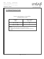
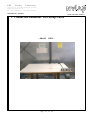
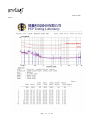
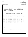
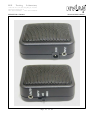
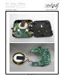
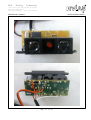
1
PEP
Testing
Laboratory
12-3Fl, No. 27-1, Lane 169, Kang-Ning St., Hsi-Chih,
Taipei Hsien, Taiwan, R. O. C.
TEL: 886-2-26922097
FAX: 886-2-26956236
REPORT NO. :E920631
NVLAP LAB CODE: 200097-0-
ņŎŊġŕņŔŕġœņőŐœŕġ
according to
AS/NZS
EQUIPMENT
MODEL NO.
APPLICANT
Κ
Κ
Κ
4251.1:1999
Door Entry Alarm System
DES-700
YUAN HSUN ELECTRIC CO., LTD.
NO. 57, CHUNG HE RD., ZUO-YING DIST., KAOHSIUNG CITY 813,
TAIWAN, R. O. C.
TEST
ENGINEER Κ
CHECKED
BY
ISSUED DATE
DENNY HUANG
Κ
JASON KUNG
Κ
JULY 23, 2004
ΘThe certificate or report shall not be reproduced except in full, without the written approval
of the laboratory.
ΘThe report must not be used by the client to claim product endorsement by NVLAP or any
agency of the United States government.
őņőġ ġ ŕņŔŕŊŏňġ ġ ōłŃŐœłŕŐœŚ
12-3Fl., No. 27-1, Lane 169, Kang-Ning St.,
Taipei Hsien, Taiwan, R. O. C.
TEL : (02) 2692-2097
FAX : (02) 2695-6236
Page 1 of 32
Hsi-Chih,
PEP
Testing
Laboratory
12-3Fl, No. 27-1, Lane 169, Kang-Ning St., Hsi-Chih,
Taipei Hsien, Taiwan, R. O. C.
TEL: 886-2-26922097
FAX: 886-2-26956236
REPORT NO. :E920631
NVLAP LAB CODE: 200097-0-
Table of Contents
1.
GENERAL
3
2.
PRODUCT INFORMATION
4
3.
EUT DESCRIPTION AND TEST CONCLUSION
5
4.
MODIFICATION(S)
6
5.
TEST SOFTWARE USED
6
6.
SUPPORT EQUIPMENT USED
7
7.
DESCRIPTION OF CONDUCTED EMISSIONS TEST
8
8.
DESCRIPTION OF RADIATED EMISSIONS TEST
9
9.
CONDUCTED EMISSIONS TEST SETUP PHOTO
12
10.
CONDUCTED EMISSIONS TEST DATA
13
11.
RADIATED EMISSIONS TEST SETUP PHOTOS
19
12.
RADIATED EMISSIONS TEST DATA
20
13.
LIST OF TEST EQUIPMENT
24
14.
LABELING REQUIREMENTS
25
15.
EUT PHOTOGRAPHS
26
Page 2 of 32
PEP
Testing
Laboratory
12-3Fl, No. 27-1, Lane 169, Kang-Ning St., Hsi-Chih,
Taipei Hsien, Taiwan, R. O. C.
TEL: 886-2-26922097
FAX: 886-2-26956236
REPORT NO. :E920631
NVLAP LAB CODE: 200097-0-
1. General
1.1 General Information
Applicant :
YUAN HSUN ELECTRIC CO., LTD.
NO. 57, CHUNG HE RD., ZUO-YING DIST., KAOHSIUNG
CITY 813, TAIWAN, R. O. C.
Manufacturer :
YUAN HSUN ELECTRIC CO., LTD.
NO. 57, CHUNG HE RD., ZUO-YING DIST., KAOHSIUNG
CITY 813, TAIWAN, R. O. C.
TEST PROCEDURE :
ANSI C63.4 (1992)
TEST FOR COMPLIANCE WITH :
AS/NZS 4251.1:1999
1. 2 Place of Measurement
őņőġ ġ ŕņŔŕŊŏňġ ġ ōłŃŐœłŕŐœŚ
12-3Fl., No. 27-1, Lane 169, Kang-Ning St.,
Taipei Hsien, Taiwan, R. O. C.
TEL : 886-2-26922097
FAX : 886-2-26956236
Hsi-Chih,
NVLAP LAB CODE 200097-0
Measurement Uncertainty :
The uncertainty of the testing result is given as below. The method of uncertainty
Calculation is provided in PEP Testing Lab document No. QP-T-28-A & QP-T-27-A
0.15 Д 30
30 Д 1000
Frequency ( MHz )
Expanded Uncertainty Ӵc
1.4 (dB)
ϡʳ 95% Confidence Level; K=2
Page 3 of 32
2.8 (dB)
PEP
Testing
Laboratory
12-3Fl, No. 27-1, Lane 169, Kang-Ning St., Hsi-Chih,
Taipei Hsien, Taiwan, R. O. C.
TEL: 886-2-26922097
FAX: 886-2-26956236
REPORT NO. :E920631
NVLAP LAB CODE: 200097-0-
2. Product Information
a.
EUT Name:
b.
Model No.
Door Entry Alarm System
c.
Κ
CPU TypeΚ
d.
CPU Frequency
e.
Crystal/Oscillator(s)
f.
Chassis Used
g.
Port/Connector(s)
h.
Power Rating
Adapter ----ManufacturerΚENG
Model No.ΚT35-9-200C-3
InputΚAC 230V 23A 50Hz
OutputΚDC 9V 200mA
i.
Condition of the EUT :
ϭ Prototype Sample Engineering Sample
ϭ Production Sample
j.
Test Item Receipt Date :
JULY 21, 2004
DES-700
N/A
Κ
Κ
Κ
N/A
Κ
4 MHz
ABS
Κ
ʳ
Input Port * 1, Output Port * 1
Page 4 of 32
PEP
Testing
Laboratory
12-3Fl, No. 27-1, Lane 169, Kang-Ning St., Hsi-Chih,
Taipei Hsien, Taiwan, R. O. C.
TEL: 886-2-26922097
FAX: 886-2-26956236
REPORT NO. :E920631
NVLAP LAB CODE: 200097-0-
3. EUT Description and Test Conclusion
The equipment under test (EUT) is Door Entry Alarm System model DES-700. The EUT that
consists of speaker, photoelectric beam sensor and reflector is used for the application at
locations such as garage door, overhead door, entrance of supermarket, restaurant, etc. The
light source of EUT is IR LED and the maximum sensing range between the photoelectric beam
sensor and reflector is 7 meters. AC-DC power adaptor supplies EUT DC 9V from AC main
power. For more detail specification about EUT, please refer to the user’s manual.
Test method: According to the major function designed, the EUT was set by the following steps
for test.
(A) Arrange the placement of EUT photoelectric beam sensor and reflector
shown as setup photos.
(B) Plug EUT photoelectric beam sensor to speaker input.
(C) Plug EUT speaker output by data cable.
The test was respectively carried out on EUT alarm function and chime function
and the worst-case test result of each test mode was recorded and provided in this
report.
Conducted emission test:
The system was setup with the EMI diagnostic software running. The power line conducted EMI
tests were run on the line and neutral conductors of the power cord and the results were recorded.
The effect of varying the position of the interface cables has been investigated to find the
worst-case configuration that produces maximum emission.
At the frequencies where the peak values of the emission exceeded the quasi-peak limit, the
emissions were also measured with the quasi-peak detectors. The average detector also measured
the emission either (A) quasi-peak values were under quasi-peak limit but exceeded average limit,
or (B) peak values were under quasi-peak limit but exceeded average limit.
Radiated emission test:
The maximum readings were found by varying the height of antenna and then rotating the turntable.
Both polarization of antenna, horizontal and vertical, are measured. The effect of varying the
position of the interface cables has been investigated to find the configuration that produces
maximum emission.
The highest emissions were also analyzed in details by operating the spectrum analyzer in fixed
tuned quasi-peak mode to determine the precise amplitude of the emissions.
Page 5 of 32
PEP
Testing
Laboratory
12-3Fl, No. 27-1, Lane 169, Kang-Ning St., Hsi-Chih,
Taipei Hsien, Taiwan, R. O. C.
TEL: 886-2-26922097
FAX: 886-2-26956236
REPORT NO. :E920631
NVLAP LAB CODE: 200097-0-
4. Modification(s):
N/A
5. Test Software Used
N/A
Page 6 of 32
PEP
Testing
Laboratory
12-3Fl, No. 27-1, Lane 169, Kang-Ning St., Hsi-Chih,
Taipei Hsien, Taiwan, R. O. C.
TEL: 886-2-26922097
FAX: 886-2-26956236
REPORT NO. :E920631
NVLAP LAB CODE: 200097-0-
6. Support Equipment Used
N/A
Page 7 of 32
PEP
Testing
Laboratory
12-3Fl, No. 27-1, Lane 169, Kang-Ning St., Hsi-Chih,
Taipei Hsien, Taiwan, R. O. C.
TEL: 886-2-26922097
FAX: 886-2-26956236
REPORT NO. :E920631
NVLAP LAB CODE: 200097-0-
7. Description of Conducted Emissions Test
7.1 Conducted Emissions
A 1m x1.5m wooden table 80 cm high is placed 40cm away from the vertical wall. Two AMN
are bonded to the grounding plane. The EUT is powered from the designated AMN and the
support equipment is powered from another designated AMN. Powers to the AMN are filtered
by a high-current high insertion loss power line filters. All electrical cables are shielded by
braided tinned copper zipper tubing with inner diameter of 1/2”. All interconnecting cables more
than 1 meter were shortened by non-inductive bundling (serpentine fashion) to a 1-meter length.
Sufficient time for the EUT, support equipment, and test equipment was allowed in order for
them to warm up to their normal operating condition. The RF output of the AMN was connected
to the spectrum analyzer to determine the frequency producing the maximum EME from the
EUT.
The spectrum was scanned from 150kHz to 30 MHz with1.5 sec sweep time. The frequency
producing the maximum level was re-examined using Quasi-Peak adapter. The detector function
was set to CISPR quasi-peak mode. The bandwidth of the receiver was set to 10kHz. The EUT,
support equipment, and interconnecting cables were re-arranged and manipulated to maximize
each EME emission. Each emission was maximized by: switching power lines; varying the mode
of operation or resolution; clock or data exchange speed; scrolling H pattern to the EUT and/or
support equipment, and powering the monitor from the floor mounted outlet box and the
computer aux AC outlet, if applicable; whichever determined the worst-case emission.
7.2 Conducted Emissions Limits
Frequency
Maximum RF Line Voltage dB(uV)
Class B
MHz
QUASI-PEAK
AVERAGE
0.15 - 0.50
66-56
56-46
0.50 - 5.0
56
46
5.0 - 30
60
50
Remarks : In the above table, the tighter limit applies at the band edges.
Page 8 of 32
PEP
Testing
Laboratory
12-3Fl, No. 27-1, Lane 169, Kang-Ning St., Hsi-Chih,
Taipei Hsien, Taiwan, R. O. C.
TEL: 886-2-26922097
FAX: 886-2-26956236
REPORT NO. :E920631
NVLAP LAB CODE: 200097-0-
8. Description of Radiated Emissions Test
8.1 Radiated Emissions
Preliminary measurements were made indoors chamber at 3 meter using broadband antennas,
broadband amplifier, and spectrum analyzer to determine the frequency producing the
maximum EME. Appropriate precaution was taken to ensure that all EME from the EUT
were maximized and investigated. The system configuration, clock speed, mode of operation
or video resolution, turntable azimuth with respect to the antenna were noted for each
frequency found. The spectrum was scanned from 30 to 1000 MHz using logbicon antenna.
Above 1GHz, linearly polarized double ridge horn antenna were used.
Final measurements were made outdoors at 10-meter test range using biconical, dipole
antenna or horn antenna. The test equipment was placed on a wooden bench situated on a
1.5x1 meter area adjacent to the measurement area. Sufficient time for the EUT, support
equipment, and test equipment was allowed in order for them to warm up to their normal
operating condition. Each frequency found during pre-scan measurements was re-examined
and investigated using Quasi-Peak Adapter. The detector function was set to CISPR
quasi-peak mode and the bandwidth of the receiver was set to 120kHz.
The half-wave dipole antenna was tuned to the frequency found during preliminary radiated
measurements. The EUT, support equipment and interconnecting cables were re-configured
to the set-up producing the maximum emission for the frequency and were placed on top
of a 0.8-meter high non-metallic 1 x 1.5 meter table. The EUT, support equipment, and
interconnecting cables were re-arranged and manipulated to maximize each EME emission.
The turntable containing the system was rotated; the antenna height was varied 1 to 4
meters and stopped at the azimuth or height producing the maximum emission. Each
emission was maximized by: varying mode of operation or resolution; clock or data
exchange speed; scrolling H pattern to the EUT and/or support equipment, and powering
the monitor from the floor mounted outlet box and the computer aux AC outlet, if
applicable; and changing the polarity of the antenna, whichever determined the worst-case
emission. Photographs of the worst-case emission can be seen in radiated emission test
photo.
Page 9 of 32
PEP
Testing
Laboratory
12-3Fl, No. 27-1, Lane 169, Kang-Ning St., Hsi-Chih,
Taipei Hsien, Taiwan, R. O. C.
TEL: 886-2-26922097
FAX: 886-2-26956236
REPORT NO. :E920631
NVLAP LAB CODE: 200097-0-
8.2 Test Configuration
10
cm
10
cm
EUT
NONCONDUCTIVE
TABLE 1.5 x 1 METER
5
5
6
80 cm TO
GROUND PLANE
7
4
2
1
8
3
40 cm
8
CONDUCTING GROUND
PLANE EXTENDS AT
LEAST 0.5m BEYOND
EUT SYSTEM FOOTPRINT
LEGEND
1.
Interconnecting cables which hang closer than 40 cm to the ground plane shall be folded back and forth forming a bundle 30 to
40 cm long. hanging approximately in the middle between ground plane and table .
2.
I/O cables which are connected to a peripheral hall be bundled in center. The end of the cable may be terminated if required
using correct terminating impedance. The total length shall not exceed 1 m.
3.
If LISN are kept in the test setup for radiated emissions, it is preferred that they be installed under the ground if requires
receptacle flush with the ground plane.
4.
Cables of hand-operated devices, such as keyboards, mouses, etc., have to be placed as close as possible to the controller.
5.
Non-EUT components of EUT system being tested.
6.
The rear of all components of the system under test shall be located flush with the rear of the table.
7.
No vertical conducting wall used.
8.
Power cords drape to the floor and are routed over to receptacle.
Page 10 of 32
PEP
Testing
Laboratory
12-3Fl, No. 27-1, Lane 169, Kang-Ning St., Hsi-Chih,
Taipei Hsien, Taiwan, R. O. C.
TEL: 886-2-26922097
FAX: 886-2-26956236
REPORT NO. :E920631
NVLAP LAB CODE: 200097-0-
8.3 Radiated Emission Limits
Limits for radiated disturbance of Class B ITE at
a measuring distance of 10 m
Frequency
MHz
Field Strength
dB(ӴV/m)
30
to
230
30
230
to
1 000
37
NOTES
1 The lower limit shall apply at the transition frequency.
2 Additional provisions may be required for cases where interference
occurs.
Page 11 of 32
PEP
Testing
Laboratory
12-3Fl, No. 27-1, Lane 169, Kang-Ning St., Hsi-Chih,
Taipei Hsien, Taiwan, R. O. C.
TEL: 886-2-26922097
FAX: 886-2-26956236
REPORT NO. :E920631
NVLAP LAB CODE: 200097-0-
9. Conducted Emissions Test Setup Photo
< FRONT VIEW >
Page 12 of 32
PEP
Testing
Laboratory
12-3Fl, No. 27-1, Lane 169, Kang-Ning St., Hsi-Chih,
Taipei Hsien, Taiwan, R. O. C.
TEL: 886-2-26922097
FAX: 886-2-26956236
REPORT NO. :E920631
NVLAP LAB CODE: 200097-0-
10. Conducted Emissions Test Data
Model No.
Frequency range
Detector
Temperature
Humidity
MEMO
Test Data :
Note
#
#
: DES-700
: 150KHz to 30MHz
: Peak Value
: 29
: 55 %
: ALARM MODE
к
ˏ ˟˜ˡ˘ʳˑ
ˏ ˡ˘˨˧˥˔˟ʳˑ
1109
1111
1. Level = Read Level + Cable Loss + Probe (LISN)
2. Over Limit = Level – Limit = Margin
Page 13 of 32
NVLAP LAB CODE:
200097-0-
Page 14 of 30
NVLAP LAB CODE:
200097-0-
Page 15 of 30
PEP
Testing
Laboratory
12-3Fl, No. 27-1, Lane 169, Kang-Ning St., Hsi-Chih,
Taipei Hsien, Taiwan, R. O. C.
TEL: 886-2-26922097
FAX: 886-2-26956236
REPORT NO. :E920631
NVLAP LAB CODE: 200097-0-
Model No.
Frequency range
Detector
Temperature
Humidity
MEMO
Test Data :
Note
#
#
: DES-700
: 150KHz to 30MHz
: Peak Value
: 29
: 55 %
: CHIME MODE
к
ˏ ˟˜ˡ˘ʳˑ
ˏ ˡ˘˨˧˥˔˟ʳˑ
1101
1099
1. Level = Read Level + Cable Loss + Probe (LISN)
2. Over Limit = Level – Limit = Margin
Page 16 of 30
NVLAP LAB CODE:
200097-0-
Page 17 of 32
NVLAP LAB CODE:
200097-0-
Page 18 of 32
PEP
Testing
Laboratory
12-3Fl, No. 27-1, Lane 169, Kang-Ning St., Hsi-Chih,
Taipei Hsien, Taiwan, R. O. C.
TEL: 886-2-26922097
FAX: 886-2-26956236
NVLAP LAB CODE: 200097-0-
REPORT NO. :E920631
11. Radiated Emissions Test Setup Photos
< FRONT VIEW >
< REAR VIEW >
Page 19 of 32
PEP
Testing
Laboratory
12-3Fl, No. 27-1, Lane 169, Kang-Ning St., Hsi-Chih,
Taipei Hsien, Taiwan, R. O. C.
TEL: 886-2-26922097
FAX: 886-2-26956236
NVLAP LAB CODE: 200097-0-
REPORT NO. :E920631
12. Radiated Emissions Test Data
Model No.
Frequency range
Frequency range
Temperature
MEMO
: DES-700
: 30MHz to 1GHz
: above 1GHz
: 29o C
: ALARM MODE
Antenna polarization :
Over
Freq.
(MHz)
Level
Limit
(dBuV/m) (dB)
Limit
Detector
Detector
Humidity
HORIZONTAL ;
Read
Line
Level
(dBuV/m) (dBuV)
: Quasi-Peak Value
: Quasi-Peak/Average Value
: 55 %
Test distance :
Antenna
Cable
Preamp
Factor
(dB)
Loss
(dB)
Factor
(dB)
10m ;
Azimuth
(̓angle)
Antenna
High(m)
!!!!68/85:!!!38/:2!!!.!3/1:!!41/11!!!48/59!!!21/38!!!1/77!!!31/61!!!!71/1!!!5/1!!!
!!!319/:94!!!31/25!!!.!:/97!!41/11!!!38/47!!!22/51!!!2/79!!!31/41!!!211/1!!!5/1!!
!!!735/184!!!35/42!!!.23/7:!!48/11!!!32/34!!!2:/61!!!4/59!!!2:/:1!!!236/1!!!4/6!!
!!!861/313!!!41/82!!!.!7/3:!!48/11!!!35/::!!!32/23!!!5/21!!!2:/61!!!284/1!!!4/6!!
!!!937/466!!!37/11!!!.22/11!!48/11!!!2:/21!!!33/13!!!5/48!!!2:/5:!!!31:/1!!!4/6!!!!
!!!:35/762!!!35/72!!!.23/4:!!48/11!!!27/25!!!34/17!!!5/62!!!2:/21!!!351/1!!!4/6
Note :
1.
2.
Level = Read Level + Antenna Factor + Cable Loss – Preamp Factor
Over Limit = Level – Limit Line
Page 20 of 32
PEP
Testing
Laboratory
12-3Fl, No. 27-1, Lane 169, Kang-Ning St., Hsi-Chih,
Taipei Hsien, Taiwan, R. O. C.
TEL: 886-2-26922097
FAX: 886-2-26956236
NVLAP LAB CODE: 200097-0-
REPORT NO. :E920631
Model No.
Frequency range
Frequency range
Temperature
MEMO
: DES-700
: 30MHz to 1GHz
: above 1GHz
: 29o C
: ALARM MODE
Antenna polarization :
Over
Freq.
(MHz)
Level
Limit
(dBuV/m) (dB)
Limit
Detector
Detector
Humidity
VERTICAL ;
Read
Line
Level
(dBuV/m) (dBuV)
: Quasi-Peak Value
: Quasi-Peak/Average Value
: 55 %
Test distance :
Antenna
Cable
Preamp
Factor
(dB)
Loss
(dB)
Factor
(dB)
10m ;
Azimuth
(̓angle)
Antenna
High(m)
!!!!46/:35!!!39/93!!!.!2/29!!!41/11!!!48/:5!!22/15!!!1/55!!!31/71!!!!:1/1!!!2/1!!!
!!!!51/545!!!39/39!!!.!2/83!!!41/11!!!47/:4!!22/46!!!1/6:!!!31/6:!!!251/1!!!2/1!!
!!!!55/587!!!36/68!!!.!5/54!!!41/11!!!45/62!!22/17!!!1/62!!!31/62!!!291/1!!!2/1!
!!!!83/892!!!35/89!!!.!6/33!!!41/11!!!47/:6!!!8/52!!!1/97!!!31/55!!!336/1!!!2/1!!!!
!!!234/7:6!!!35/1:!!!.!6/:2!!!41/11!!!42/19!!23/52!!!2/19!!!31/59!!!381/1!!!2/1!!
!!!937/52:!!!38/65!!!.!:/57!!!48/11!!!31/75!!33/13!!!5/48!!!2:/5:!!!3:1/1!!!2/6
Note :
1.
2.
Level = Read Level + Antenna Factor + Cable Loss – Preamp Factor
Over Limit = Level – Limit Line
Page 21 of 32
PEP
Testing
Laboratory
12-3Fl, No. 27-1, Lane 169, Kang-Ning St., Hsi-Chih,
Taipei Hsien, Taiwan, R. O. C.
TEL: 886-2-26922097
FAX: 886-2-26956236
NVLAP LAB CODE: 200097-0-
REPORT NO. :E920631
Model No.
Frequency range
Frequency range
Temperature
MEMO
: DES-700
: 30MHz to 1GHz
: above 1GHz
: 29o C
: CHIME MODE
Antenna polarization :
Over
Freq.
(MHz)
Level
Limit
(dBuV/m) (dB)
Limit
Detector
Detector
Humidity
HORIZONTAL ;
Read
Line
Level
(dBuV/m) (dBuV)
: Quasi-Peak Value
: Quasi-Peak/Average Value
: 55 %
Test distance :
Antenna
Cable
Preamp
Factor
(dB)
Loss
(dB)
Factor
(dB)
10m ;
Azimuth
(̓angle)
Antenna
High(m)
!!!!68/85:!!!37/:2!!.!4/1:!!!41/11!!!47/59!!!21/38!!!1/77!!!31/61!!225/1!!!5/1!!!!
!!!319/:94!!!34/25!!.!7/97!!!41/11!!!41/47!!!22/51!!!2/79!!!31/41!!261/1!!!5/1!!!!
!!!735/184!!!37/42!!.21/7:!!!48/11!!!34/34!!!2:/61!!!4/59!!!2:/:1!!283/1!!!4/6!!!
!!!861/313!!!41/82!!.!7/3:!!!48/11!!!35/::!!!32/23!!!5/21!!!2:/61!!325/1!!!4/6!!!!!
!!!937/466!!!38/11!!.21/11!!!48/11!!!31/21!!!33/13!!!5/48!!!2:/5:!!381/1!!!4/6!!!!
!!!:35/762!!!31/72!!.27/4:!!!48/11!!!23/25!!!34/17!!!5/62!!!2:/21!!41:/1!!!4/6
Note :
1. Level = Read Level + Antenna Factor + Cable Loss – Preamp Factor
2. Over Limit = Level – Limit Line
Page 22 of 32
PEP
Testing
Laboratory
12-3Fl, No. 27-1, Lane 169, Kang-Ning St., Hsi-Chih,
Taipei Hsien, Taiwan, R. O. C.
TEL: 886-2-26922097
FAX: 886-2-26956236
NVLAP LAB CODE: 200097-0-
REPORT NO. :E920631
Model No.
Frequency range
Frequency range
Temperature
MEMO
: DES-700
: 30MHz to 1GHz
: above 1GHz
: 29o C
: CHIME MODE
Antenna polarization :
Over
Freq.
(MHz)
Level
Limit
(dBuV/m) (dB)
Limit
Detector
Detector
Humidity
VERTICAL ;
Read
Line
Level
(dBuV/m) (dBuV)
: Quasi-Peak Value
: Quasi-Peak/Average Value
: 55 %
Test distance :
Antenna
Cable
Preamp
Factor
(dB)
Loss
(dB)
Factor
(dB)
10m ;
Azimuth
(̓angle)
Antenna
High(m)
!!!!46/:35!!!38/93!!!.!3/29!!!41/11!!47/:5!!!22/15!!!1/55!!!31/71!!!!81/1!!!2/1!!
!!!!51/545!!!38/39!!!.!3/83!!!41/11!!46/:4!!!22/46!!!1/6:!!!31/6:!!!271/1!!!2/1!!!
!!!!55/587!!!37/68!!!.!4/54!!!41/11!!46/62!!!22/17!!!1/62!!!31/62!!!351/1!!!2/1!
!!!!83/892!!!36/89!!!.!5/33!!!41/11!!48/:6!!!!8/52!!!1/97!!!31/55!!!3:1/1!!!2/1!!
!!!234/7:6!!!31/1:!!!.!:/:2!!!41/11!!38/19!!!23/52!!!2/19!!!31/59!!!433/1!!!2/6!!
!!!937/52:!!!36/65!!!.22/57!!!48/11!!29/75!!!33/13!!!5/48!!!2:/5:!!!461/1!!!2/6
Note :
1. Level = Read Level + Antenna Factor + Cable Loss – Preamp Factor
2. Over Limit = Level – Limit Line
Page 23 of 32
PEP
Testing
Laboratory
12-3Fl, No. 27-1, Lane 169, Kang-Ning St., Hsi-Chih,
Taipei Hsien, Taiwan, R. O. C.
TEL: 886-2-26922097
FAX: 886-2-26956236
NVLAP LAB CODE: 200097-0-
REPORT NO. :E920631
13. List of Test Equipment
Test Mode
Instrument
R&S
Receiver
Rolf Heine
LISN
R&S
Conduction
LISN
( No.1)
Spectrum
Analyzer
RF Cable
Schaffner
ISN
R&S
Receiver
Schaffner
Pre-amplifier
Radiation
(OP No.1)
Model No.
Serial No.
ESHS10
830223/008
May 22, 2005
1Year
NNB-4/63TL
98008
May 01, 2005
1Year
ESH3-Z5
844982/039
Aug. 06, 2004
1Year
R3261A
91720076
June 08, 2005
1Year
Rg400
N/A
May 12, 2005
1Year
T411
N/A
June 29, 2005
1Year
ESVS30
863342/012
May 22, 2005
1Year
CPA9232
1028
May 20, 2005
1Year
10095
May 21, 2005
2Year
June 26, 2006
3Year
COM-Power
AH-118
Horn Ant.
(1GHz~18GHz)
Schwarzbeck
Next Cal. Date Cal. Interval
VHAP
970 + 971
(30MHz~1GHz)
953 + 954
SMY01
841104/037
Apr. 29, 2005
2Year
RF Cable
No. 1
N/A
May 11, 2005
1Year
EMCO
3142B
Antenna
(26MHz~2GHz)
9904-1370
Aug. 24, 2004
1Year
Precision Dipole
Ant
R &S Signal
Generator
Page 24 of 32
PEP
Testing
Laboratory
12-3Fl, No. 27-1, Lane 169, Kang-Ning St., Hsi-Chih,
Taipei Hsien, Taiwan, R. O. C.
TEL: 886-2-26922097
FAX: 886-2-26956236
NVLAP LAB CODE: 200097-0-
REPORT NO. :E920631
14. Labeling Requirements
The mark should adhere to specific guidelines for appearance and location, as follows:
1.
2.
3.
4.
5.
The mark must be placed on an external surface of the product, near the model ID; or
If the above is impractical, the mark should appear on the labeling, packaging, or
warranty;
The mark must be applied by durable means such as printing, painting, or molding;
The mark’s color should ensure its visibility and contrast; and
The domestic manufacturer, or its agent or importer, must be identified.
Page 25 of 32
PEP
Testing
Laboratory
12-3Fl, No. 27-1, Lane 169, Kang-Ning St., Hsi-Chih,
Taipei Hsien, Taiwan, R. O. C.
TEL: 886-2-26922097
FAX: 886-2-26956236
NVLAP LAB CODE: 200097-0-
REPORT NO. :E920631
15. EUT Photographs
MODEL
NO. : DES-700
Page 26 of 32
PEP
Testing
Laboratory
12-3Fl, No. 27-1, Lane 169, Kang-Ning St., Hsi-Chih,
Taipei Hsien, Taiwan, R. O. C.
TEL: 886-2-26922097
FAX: 886-2-26956236
NVLAP LAB CODE: 200097-0-
REPORT NO. :E920631
Page 27 of 32
PEP
Testing
Laboratory
12-3Fl, No. 27-1, Lane 169, Kang-Ning St., Hsi-Chih,
Taipei Hsien, Taiwan, R. O. C.
TEL: 886-2-26922097
FAX: 886-2-26956236
NVLAP LAB CODE: 200097-0-
REPORT NO. :E920631
Page 28 of 32
PEP
Testing
Laboratory
12-3Fl, No. 27-1, Lane 169, Kang-Ning St., Hsi-Chih,
Taipei Hsien, Taiwan, R. O. C.
TEL: 886-2-26922097
FAX: 886-2-26956236
NVLAP LAB CODE: 200097-0-
REPORT NO. :E920631
Page 29 of 32
PEP
Testing
Laboratory
12-3Fl, No. 27-1, Lane 169, Kang-Ning St., Hsi-Chih,
Taipei Hsien, Taiwan, R. O. C.
TEL: 886-2-26922097
FAX: 886-2-26956236
NVLAP LAB CODE: 200097-0-
REPORT NO. :E920631
Page 30 of 32
PEP
Testing
Laboratory
12-3Fl, No. 27-1, Lane 169, Kang-Ning St., Hsi-Chih,
Taipei Hsien, Taiwan, R. O. C.
TEL: 886-2-26922097
FAX: 886-2-26956236
NVLAP LAB CODE: 200097-0-
REPORT NO. :E920631
Page 31 of 32
PEP
Testing
Laboratory
12-3Fl, No. 27-1, Lane 169, Kang-Ning St., Hsi-Chih,
Taipei Hsien, Taiwan, R. O. C.
TEL: 886-2-26922097
FAX: 886-2-26956236
NVLAP LAB CODE: 200097-0-
REPORT NO. :E920631
Page 32 of 32
CERTIFICATE OF COMPLIANCE
APPLICANT
:
YUAN HSUN ELECTRIC CO., LTD.
ADDRESS
:
NO. 57, CHUNG HE RD., ZUO-YING DIST., KAOHSIUNG
CITY 813, TAIWAN, R. O. C.
PRODUCT NAME
:
Door Entry Alarm System
MODEL NO.
:
DES-700
REPORT NO.
:
E920631
THIS IS TO CERTIFY, ON THE BASIS OF THE TESTS UNDERTAKEN,
THE SUBMITTED SAMPLES OF THE ABOVE ITEM IS CONSIDERED TO
COMPLY WITH :
AS/NZS
4251.1:1999
SIGNED FOR AND ON BEHALF OF
PEP TESTING LABORATORY
NVLAP LAB CODE: 200097-0
Peter Kao
President, NVLAP Signatory
Date :
JULY 23, 2004