1
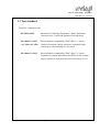
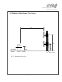
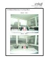
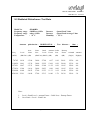
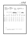
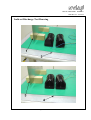
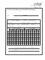
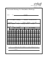
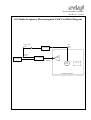
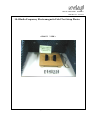
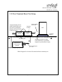
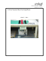
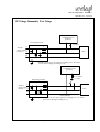
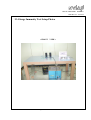
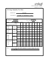
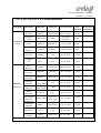
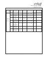
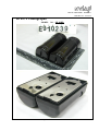
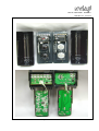
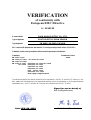
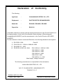
NVLAP LAB CODE:200097-0
REPORT NO. : E910239
EMC TEST REPORT
According to
EN 55022:1998
EN 50130-4:1995+A1:1998
: EN 61000-3-2:1995+A1: 1998+A2: 1998
EN 61000-3-3:1995
: EN 61000-4-2:1995+A1:1998
EN 61000-4-3 / EN 61000-4-4
EN 61000-4-5 / ENV 50141 / EN 61000-4-11
Main Supply Voltage Variations
EQUIPMENT
: PHOTOELECTRIC BEAM SENSOR
MODEL NO.
: PB-80HD, PB-60HD, PB-30HD
APPLICANT
: YUAN HSUN ELECTRIC CO., LTD.
NO. 57, CHUNG-HE RD., KAOHSIUMG CITY, TAIWAN,
R. O. C.
Test Engineer
:
JOHSONG CHANG
Checked
:
JASON GONG
Issued Date
by
:
APR.
09,
2002
•The test report shall not be reproduced except in full, without the written approval of the
laboratory.
•The report can’t be used by the client to claim product endorsement by PEP Testing
Laboratory.
•This report is only for the equipment which described in page 7.
Page 1 of 46
NVLAP LAB CODE:200097-0
REPORT NO. : E910239
TABLE
OF
CONTENTS
1.
General
1.1 General Information
1.2 Place of Measurement
1.3 Test standard
4
2.
Product Information
7
3.
EUT Description and Test Methods
8
4.
Modification
9
5.
Software Used
9
6.
Support Equipment Used
10
7.
EN 55022 Conducted Disturbance Test
11
8.
EN
8.1
8.2
8.3
8.4
8.5
55022 Radiated Disturbance Test
Test Description
Test Setup
Test Limits
Test Setup photo
Test Data
12
9.
EN
9.1
9.2
9.3
9.4
9.5
61000-4-2 Electrostatic Discharge Test
Test Description
Test Setup
Test Limits
Direct Discharge Drawing
Test Data
18
Page 2 of 46
NVLAP LAB CODE:200097-0
REPORT NO. : E910239
10. EN
10.1
10.2
10.3
10.4
61000-4-3 Radio-Frequency Electromagnetic Field Test
Test Description
Test Block Diagram
Test Limits
Test Setup Photo
26
11. EN 61000-4-4 Fast Transient Burst Test
11.1 Test Description
11.2 Test Setup
11.3 Test Limits
11.4 Test Setup Photo
11.5 Test Data
31
12. EN 61000-4-5 Surge Immunity Test
12.1 Test Description
12.2 Test Setup
12.3 Test Limits
12.4 Test Setup Photo
12.5 Test Data
37
13. The List of Test Instruments
43
14. EUT Photographs
45
Page 3 of 46
NVLAP LAB CODE:200097-0
REPORT NO. : E910239
1. General
1.1 General Information :
Applicant :
YUAN HSUN ELECTRIC CO., LTD.
NO. 57, CHUNG-HE RD., KAOHSIUMG CITY, TAIWAN,
R. O. C.
Manufacturer :
YUAN HSUN ELECTRIC CO., LTD.
NO. 57, CHUNG-HE RD., KAOHSIUMG CITY, TAIWAN,
R. O. C.
Measurement Procedure : EN 55022 & EN 50130-4
Measurement Uncertainty :
The uncertainty of the testing result is given as below . The method of uncertainty
Calculation is provided in PEP Testing Lab. document No. PEPD-15 .
0.15 ∼ 30
30 ∼ 1000
Frequency ( MHz )
1.77 (dB)
Combined Uncertainty μc
2.08 (dB)
1.2 Place of Measurement
PEP
TESTING
LABORATORY
12-3Fl, No. 27-1, Lane 169, Kang-Ning
Taipei Hsien, Taiwan, R. O. C.
TEL : 8862-26922097 FAX : 8862-26956236
St.,
Hsi-Chin.
NVLAP LAB CODE 200097-0
FCC Registration No. : 90868
Nemko Aut. No. : ELA133
BSMI Aut. No. : SL2-IN-E-11,SL2-A1-E-11
VCCI Registration No. : C-493/R-477
Page 4 of 46
NVLAP LAB CODE:200097-0
REPORT NO. : E910239
1.3 Test standard
Tested for compliance with :
EN 55022:1998
- Information Technology Equipment – Radio disturbance
characteristics - Limits and methods of measurement
EN 61000-3-2:1995 - Electromagnetic compatibility (EMC) Part 3-2: Limits –
+A1: 1998+A2: 1998 Limits for harmonic current emissions (equipment input
Current up to and including 16A per phase
EN 61000-3-3:1995
- Electromagnetic compatibility (EMC) Part 3-2: Limits –
Limitation of voltage fluctuations and flicker in low-voltage
supply systems for equipment with rated current up to 16A
Page 5 of 46
NVLAP LAB CODE:200097-0
REPORT NO. : E910239
EN 50130-4:1995+A1: 1998
- Alarm systems – Part 4. Electromagnetic compatibility
Product family standard: Immunity requirements
for components of fire, intruder and social alarm systems
EN 61000-4-2:1995+A1: 1998
- Electromagnetic compatibility (EMC) Part 4: Testing and
measurement techniques, Section 2: Electrostatic discharge
immunity test Basic EMC Publication
EN 61000-4-3:1996
- Electromagnetic compatibility (EMC) Part 4: Testing and
measurement techniques, Section 3: Radiated, radioFrequency, electromagnetic field immunity test
EN 61000-4-4:1995
- Electromagnetic compatibility (EMC) Part 4: Testing and
measurement techniques, Section 4: Electrical fast transient
/ Burst immunity test Basic EMC publication
EN 61000-4-5: 1995
- Electromagnetic compatibility (EMC) Part 4: Testing and
measurement techniques, Section 5: Surge immunity test
(includes corrigendum: 1995)
EN 50141:1993
- Electromagnetic compatibility –Basic immunity
standard–Conducted disturbances induced by
radio-frequency fields–Immunity test
EN 61000-4-11: 1994
- Electromagnetic compatibility (EMC) Part 4: Testing and
measurement techniques, Section 11: Voltage dips, short
interruptions and voltage variations immunity tests
Page 6 of 46
NVLAP LAB CODE:200097-0
REPORT NO. : E910239
2. Product Information
a.
EUT Type:
PHOTOELECTRIC BEAM SENSOR
b. Model:
PB-80HD
c.
Chipset Type:
N/A
d. System speed:
N/A
e.
Crystal/Oscillator(s) :N/A
f.
Port/connector(s) :
g.
Memory Expansion: N/A
N/A
h. Power Rating:
DC 12V ----From DC Power Supplier
i.
Chassis Used:
ABS
j.
Condition of the EUT :
□ Prototype Sample 3 Engineering Sample
□ Production Sample
k. Test Item Receipt Date : MAR.
/
Page 7 of 46
28
/
2002
NVLAP LAB CODE:200097-0
REPORT NO. : E910239
3. EUT Description
The equipment under test (EUT) is PHOTOELECTRIC BEAM SENSOR model
PB-80HD, PB-60HD and PB-30HD. These models have identical electrical design and
construction except their maximum beam ranges are different (PB-80HD: outdoor 80M,
PB-60HD: outdoor 60M, PB-30HD: outdoor 30M). After verifying these models, we
only took the worst-case model PB-80HD for test. The EUT consists of one transmitter
and one receiver. Power provided to EUT is DC 12V from DC Power Supplier. For
more detail specification about EUT, please refer to the user’s manual.
Test method: The EUT powered by DC power source was placed on turntable for test.
Test engineer tried to obtain the worst-case test data by placing
obstruction between transmitter and receiver to trigger off operating
during the test. The worst-case test result was recorded and provided in
this report.
As pre-scan, we took radiated emission first. EUT configuration including peripheral
devices placement and data cables coupling was compliant with EN55022 requirement.
Test engineer tried to find the worst data cables coupling in order to perform the final
test that radiated emission would keep the same configuration under test.
Conducted emission test:
N/A
Radiated emission test:
The maximum readings were found by varying the height of antenna and then rotating
the turntable. Both polarization of antenna, horizontal and vertical, are measured. The
effect of varying the position of the interface cables has been investigated to find the
configuration that produces maximum emission.
The highest emissions were also analyzed in details by operating the spectrum analyzer
in fixed tuned quasi-peak mode to determine the precise amplitude of the emissions.
While doing so, the antenna height was varied between one and four meters, and the
turntable was slowly rotated, to maximize the emission.
Page 8 of 46
NVLAP LAB CODE:200097-0
REPORT NO. : E910239
4. Modification(s):
N/A
5. Test Software Used
N/A
Page 9 of 46
NVLAP LAB CODE:200097-0
REPORT NO. : E910239
6. Support Equipment Used
1.DC1
FCC ID:N/A
Manufacturer:MEEILEHLIH
Model Number:TH-1225A
Power Supply:Linear
Power Cord:N/A
Data Cable:N/A
Page 10 of 46
NVLAP LAB CODE:200097-0
REPORT NO. : E910239
7. EN 55022 Conducted Disturbance Test
Test Standard
Model No.
Result
EN 55022:1998
PB-80HD
N/A
Note:
(a) In technical view, this product cannot generate disturbances above the limit
As defined in the standard, so we didn’t do the test.
Page 11 of 46
NVLAP LAB CODE:200097-0
REPORT NO. : E910239
8. EN 55022 Radiated Disturbance Test
Test Standard
EN 55022
Model
No.
PB-80HD
Result
Passed
8.1 Radiated Disturbance Test Description
Preliminary measurements were made indoors chamber at 3 meter using broadband
antennas, broadband amplifier, and spectrum analyzer to determine the frequency
producing the maximum EME. Appropriate precaution was taken to ensure that all
EME from the EUT were maximized and investigated. The system configuration,
clock speed, mode of operation or video resolution, turntable azimuth with respect to
the antenna were noted for each frequency found. The spectrum was scanned from 30
to 1000 MHz using logbicon antenna. Above 1GHz, linearly polarized double ridge
horn antenna were used.
Final measurements were made outdoors at 10-meter test range using biconical,
dipole antenna or horn antenna. The test equipment was placed on a wooden bench
situated on a 1.5x1 meter area adjacent to the measurement area. Sufficient time for
the EUT, support equipment, and test equipment was allowed in order for them to
warm up to their normal operating condition. Each frequency found during pre-scan
measurements was re-examined and investigated using Quasi-Peak Adapter. The
detector function was set to CISPR quasi-peak mode and the bandwidth of the
receiver was set to 120kHz.
The half-wave dipole antenna was tuned to the frequency found during preliminary
radiated measurements. The EUT, support equipment and interconnecting cables
were re-configured to the set-up producing the maximum emission for the frequency
and were placed on top of a 0.8-meter high non-metallic 1 x 1.5 meter table. The
EUT, support equipment, and interconnecting cables were re-arranged and
manipulated to maximize each EME emission. The turntable containing the system
was rotated; the antenna height was varied 1 to 4 meters and stopped at the azimuth
or height producing the maximum emission.
Page 12 of 46
NVLAP LAB CODE:200097-0
REPORT NO. : E910239
8.2 Radiated Disturbance Test Setup
10m
4m
(EUT)
1m
GROUND
PLANE
0.8m
TURN TABLE
TO RECEIVER
EUT = Equipment Under Test
Page 13 of 46
NVLAP LAB CODE:200097-0
REPORT NO. : E910239
8.3 Radiated Disturbance Test Limits
Limits for radiated disturbance of Class A ITE at
a measuring distance of 10 m
Frequency
MHz
Field Strength
dB(μV/m)
30
to
230
40
230
to
1 000
47
NOTES
1 The lower limit shall apply at the transition frequency.
2 Additional provisions may be required for cases where interference
occurs.
Limits for radiated disturbance of Class B ITE at
a measuring distance of 10 m
Frequency
MHz
Field Strength
dB(μV/m)
30
to
230
30
230
to
1 000
37
NOTES
1 The lower limit shall apply at the transition frequency.
2 Additional provisions may be required for cases where interference
occurs.
Page 14 of 46
NVLAP LAB CODE:200097-0
REPORT NO. : E910239
8.4 Radiated Disturbance Test Setup Photo.
< FRONT VIEW >
< REAR VIEW >
Page 15 of 46
NVLAP LAB CODE:200097-0
REPORT NO. : E910239
8.5 Radiated Disturbance Test Data
Model No.
Frequency range
Frequency range
Temperature
Antenna
: PB-80HD
: 30MHz to 1GHz
: above 1GHz
: 23o C
polarization : HORIZONTAL
Over
Freq.
(MHz)
Level
Limit
(dBuV/m) (dB)
74.745 14.14
119.829 14.61
127.921 14.67
173.836 13.84
239.904 16.48
450.199 22.91
Detector
Detector
Humidity
-15.86
-15.39
-15.33
-16.16
-20.52
-14.09
Limit
Read
: Quasi-Peak Value
: Quasi-Peak/Average Value
: 55 %
; Test distance :
Antenna Cable
Preamp
Line
Level Factor
(dBuV/m) (dBuV) (dB)
Loss
(dB)
Factor
(dB)
30.00
30.00
30.00
30.00
37.00
37.00
0.10
0.30
0.30
0.60
1.02
1.76
20.01
20.00
19.85
19.85
19.40
20.38
27.98
22.22
23.00
24.23
23.53
25.13
6.07
12.09
11.22
8.86
11.33
16.40
Azimuth Antenna
(°
angle) High(m)
255.0
253.0
258.0
251.0
252.0
256.0
Note :
1.
2.
Level = Read Level + Antenna Factor + Cable Loss – Preamp Factor
Over Limit = Level – Limit Line
Page 16 of 46
10m ;
4.0
4.0
4.0
4.0
4.0
3.8
NVLAP LAB CODE:200097-0
REPORT NO. : E910239
Model No.
Frequency range
Frequency range
Temperature
Antenna
: PB-80HD
: 30MHz to 1GHz
: above 1GHz
: 23o C
polarization : VERTICAL
Over
Freq.
(MHz)
Level
Limit
(dBuV/m) (dB)
31.632 17.03
120.413 16.87
127.340 16.78
172.055 13.80
230.256 13.12
449.445 21.91
Detector
Detector
Humidity
-12.97
-13.13
-13.22
-16.20
-23.88
-15.09
Limit
Read
: Quasi-Peak Value
: Quasi-Peak/Average Value
: 55 %
; Test distance :
Antenna Cable
Preamp
Line
Level Factor
(dBuV/m) (dBuV) (dB)
Loss
(dB)
Factor
(dB)
30.00
30.00
30.00
30.00
37.00
37.00
0.10
0.30
0.30
0.60
0.94
1.76
19.93
19.93
19.80
19.79
19.80
20.39
19.39
24.46
25.00
24.03
22.02
24.13
17.47
12.04
11.28
8.96
9.96
16.41
10m ;
Azimuth Antenna
(°
angle) High(m)
259.0
250.0
251.0
254.0
253.0
254.0
Note :
1.
2.
Level = Read Level + Antenna Factor + Cable Loss – Preamp Factor
Over Limit = Level – Limit Line
Page 17 of 46
1.0
1.0
1.0
1.0
1.0
1.1
NVLAP LAB CODE:200097-0
REPORT NO. : E910239
9. EN 61000-4-2 Electrostatic Discharge Test
Test standard
Model
No.
EN 61000-4-2
PB-80HD
Result
Passed
Criteria for Compliance:
There shall be no damage, malfunction or change of status due to the conditioning.
Flickering of an indicator during the application of the discharges is permissable,
providing that there is no residual change in the EUT or any change in outputs.
Page 18 of 46
NVLAP LAB CODE:200097-0
REPORT NO. : E910239
9.1 Electrostatic Discharge Test Description
This standard relates to equipment, systems, sub-systems and peripherals which may be
involved in static electricity discharges owing to environmental and installation conditions.
such as low relative humidity, use of low-conductivity (artificial-fibre) carpets, vinyl
garments, etc., which may exist in allocations classified in standards relevant to electrical
and electronic equipment.
The test set-up shall consist of a wooden able, 0.8 m high standing on the ground reference
plane. A horizontal coupling plane(HCP), 1.6 m x 0.8 m, shall be placed on the table. The
EUT and cables shall be isolated from the coupling plane by an insulating support 0.5 mm
thick .
A ground reference plane shall be provided on floor of the laboratory. It shall be metallic
sheet of 0.25 mm minimum thickness. The minimum size of the reference plane is 1 m, the
exact size depending on the dimensions of the EUT .
It shall project beyond the EUT or coupling plane by at least 0.5 m on all sides. and shall be
connected to the protective grounding system.
In order to minimize the impact of environmental parameters on test results, the tests shall be
carried out in climatic and electromagnetic reference conditions.
Climatic conditions
- ambient temperature:
15 ℃ to 35℃;
- relative humidity:
30 % to 60%
- atmospheric pressure:
86 KPa (860 mbar) to 106 KPa (1 060 mbar).
NOTE – Any other values are specified in the product specification.
Electromagnetic conditions
The electromagnetic environment of the laboratory shall not influence the test results.
Page 19 of 46
NVLAP LAB CODE:200097-0
REPORT NO. : E910239
9.2 Electrostatic Discharge Test Setup
- Example of test set-up for table-top equipment,
laboratory tests
Page 20 of 46
NVLAP LAB CODE:200097-0
REPORT NO. : E910239
9.3 Electrostatic Discharge Test Limits
Test voltages1):
Air discharges
(kV)
2; 4 & 8
Contact discharges
(kV)
2; 4 & 6
Polarity
+&-
Number of discharges per point for each voltage and polarity 10
Interval between discharges
(s)
1)
The test voltages specified are the open-circuit voltages.
The test voltages for the lower severity levels are included
because all the lower severity levels must also be satisfied.
Page 21 of 46
=1
NVLAP LAB CODE:200097-0
REPORT NO. : E910239
9.4 Direct Discharge Test Drawing
Page 22 of 46
NVLAP LAB CODE:200097-0
REPORT NO. : E910239
Indirect Discharge Test Drawing
Page 23 of 46
NVLAP LAB CODE:200097-0
REPORT NO. : E910239
9.5 Electrostatic Discharge Test Data(Direct Discharge)
Model
No. :
PB-80HD
Test Item : Direct Discharge
Temperature :
℃
26
: NoiseKen ESS-100L
Relative Humidity :
Storage Capacitor : 150 pf
Discharge Rate
Instrument
46
%RH
Discharge Resistor : 330 Ohm
: < 1 / Sec
Contact Discharge
Air Discharge
2 KV
4 KV
6 KV
8 KV
2 KV
4 KV
8 KV
15 KV
+
-
+
-
+
-
+
-
+
-
+
-
+
-
+
-
1
P
P
P
P
P
P
/
/
P
P
P
P
P
P
/
/
2
P
P
P
P
P
P
/
/
P
P
P
P
P
P
/
/
3
P
P
P
P
P
P
/
/
P
P
P
P
P
P
/
/
4
P
P
P
P
P
P
/
/
P
P
P
P
P
P
/
/
5
P
P
P
P
P
P
/
/
P
P
P
P
P
P
/
/
6
P
P
P
P
P
P
/
/
P
P
P
P
P
P
/
/
7
P
P
P
P
P
P
/
/
P
P
P
P
P
P
/
/
8
P
P
P
P
P
P
/
/
P
P
P
P
P
P
/
/
9
P
P
P
P
P
P
/
/
P
P
P
P
P
P
/
/
10
P
P
P
P
P
P
/
/
P
P
P
P
P
P
/
/
1.
2.
P
“
“
/
” - - - - means the EUT function is correct during the test .
” - - - - no test.
Page 24 of 46
NVLAP LAB CODE:200097-0
REPORT NO. : E910239
Electrostatic Discharge Test Data(Indirect Discharge)
Model
No. :
PB-80HD
Test Item : Indirect Discharge
Temperature :
℃
26
Relative Humidity :
Storage Capacitor : 150 pf
Discharge Rate
Instrument : NoiseKen ESS-100L
46
%RH
Discharge Resistor : 330 Ohm
: < 1 / Sec
Contact Discharge
Air Discharge
2 KV
4 KV
6 KV
8 KV
2 KV
4 KV
8 KV
15 KV
+
-
+
-
+
-
+
-
+
-
+
-
+
-
+
-
1
P
P
P
P
P
P
/
/
/
/
/
/
/
/
/
/
2
P
P
P
P
P
P
/
/
/
/
/
/
/
/
/
/
3
P
P
P
P
P
P
/
/
/
/
/
/
/
/
/
/
4
P
P
P
P
P
P
/
/
/
/
/
/
/
/
/
/
5
/
/
/
/
/
/
/
/
/
/
/
/
/
/
/
/
6
/
/
/
/
/
/
/
/
/
/
/
/
/
/
/
/
7
/
/
/
/
/
/
/
/
/
/
/
/
/
/
/
/
8
/
/
/
/
/
/
/
/
/
/
/
/
/
/
/
/
9
/
/
/
/
/
/
/
/
/
/
/
/
/
/
/
/
10
/
/
/
/
/
/
/
/
/
/
/
/
/
/
/
/
1.
2.
P
“
“
/
” - - - - means the EUT function is correct during the test .
” - - - - no test.
Page 25 of 46
NVLAP LAB CODE:200097-0
REPORT NO. : E910239
10. EN 61000-4-3 Radio-Frequency Electromagnetic
Field Test
Test standard
Model No.
Result
EN 61000-4-3
PB-80HD
Passed
Field Strength : 10
Modulation :
Start :
AM 80 % , 1KHz .
80 MHz ,
Pulse modulation:
Start :
V/M ,
80 MHz ,
Stop :
ON ( YES ) . OFF (
1000 MHz .
1 Hz
DC Power : 12 Vac
ON ( YES ) . OFF (
Stop :
1000 MHz .
)
)
DC Power : 12 Vac
Criteria for Compliance:
There shall be no damage, malfunction or change of status due to the conditioning.
Flickering of an indicator during the conditioning is permissable, providing that
there is no residual change in the EUT or any change in outputs.
Page 26 of 46
NVLAP LAB CODE:200097-0
REPORT NO. : E910239
10.1 Radio-Frequency Electromagnetic Field Test Description
Most electronic equipment is, in some manner, affected by electromagnetic radiation.
This radiation is frequently generated by such sources as the small hand-held radio
transceivers that are used by operating, maintenance and security personnel, fixed-station
radio and television transmitters, vehicle radio transmitters, and various industrial
electromagnetic sources.
In addition to electromagnetic energy deliberately generated, there is also spurious radiation
caused by devices such as welders, thyristors, fluorescent lights, switches operating inductive
loads, etc. For the most part, this interference manifests itself as conducted electrical
interference and, as such, is dealt with in other parts of this standard. Methods employed to
prevent effects from electromagnetic fields will normally also reduce the effects from these
sources.
The electromagnetic environment is determined by the strength of the electromagnetic field
(field strength in volts per metre). The field strength is not easily measured without
sophisticated instrumentation nor is it easily calculated by classical equations and formulae
because of the effect of surrounding structures or the proximity of other equipment that will
distort and/or reflect the electromagnetic waves.
All testing of equipment shall be performed in a configuration as close as possible to the
installed case. Wiring shall be consistent with the manufacturer’s recommended procedures,
and the equipment shall be in its housing with all covers and access panels in place, unless
otherwise stated.
If the equipment is designed to be mounted in a panel, rack or cabinet, it shall be tested in
this configuration.
Page 27 of 46
NVLAP LAB CODE:200097-0
REPORT NO. : E910239
10.2 Radio-Frequency Electromagnetic Field Test Block Diagram
Field Leveling
Signal
Fiber
Optic
Cable
Field Monitor
Detector
Input
Power Amplifier
RF Source
RF Input
Bulkhead
Feedthrough
Antenna
Field
Probe
Anechoic Chamber
Page 28 of 46
EUT
NVLAP LAB CODE:200097-0
REPORT NO. : E910239
10.3 Radio-Frequency Electromagnetic Field Test Limits
Frequency range
Field strength1)
Modulation:
Amplitude modulation
Pulse modulation
1)
(MHz)
(V/m)
80 to 1000
10
80%, 1 kHz, sinusoidal
1 Hz (0.5 s ON: 0.5 s OFF)
The field strength quoted is the RMS value for the continuous wave, before modulation.
Page 29 of 46
NVLAP LAB CODE:200097-0
REPORT NO. : E910239
10.4 Radio-Frequency Electromagnetic Field Test Setup Photos
< FRONT VIEW >
Page 30 of 46
NVLAP LAB CODE:200097-0
REPORT NO. : E910239
11. EN 61000-4-4 Fast Transient Burst Test
Test standard
Model No.
Result
EN 61000-4-4
PB-80HD
Passed
Criteria for Compliance:
There shall be no damage, malfunction or change of status due to the conditioning.
Flickering of an indicator during the application of the bursts is permissable, providing
that there is no residual change in the EUT or any change in outputs.
Page 31 of 46
NVLAP LAB CODE:200097-0
REPORT NO. : E910239
11.1 Fast Transient Bursts Test Description
The repetitive fast transient test is a test with bursts consisting of a number of fast transients,
coupled into power supply, control and signal ports of electrical and electronic equipment.
Significant for the test are the short rise time, the repetition rate and the low energy of the
transients.
The test shall be carried out on the basis of a test plan including verification of the
performances of the EUT as defined in the technical specification.
Climatic conditions
The tests shall be carried out in standard climatic conditions in accordance with IEC 68-1:
- ambient temperature:
15℃ to 35℃
- relative humidity:
25% to 75%
- atmospheric pressure:
86kPa (860 mbar) to 106Kpa (1 060 mbar)
NOTE – Any other values are specified in the product specification.
Electromagnetic conditions
The electromagnetic conditions of the laboratory shall be such to guarantee the correct
operation of the EUT in order not to influence the test results.
Page 32 of 46
NVLAP LAB CODE:200097-0
REPORT NO. : E910239
11.2 Fast Transient Burst Test Setup
Couping/decupling sections
shall be mounted directly on
the reference ground plane.
Bonding connections shall be
as short as possibke.
Lines
Decoupling
network
Lines/terminals
to be tested
Capacitor
or clamp
Coupling
device
Reference plane
Electrical fast
transievt/burst
generator
EUT
lnsulating
support
Grounding conection according
to the manufacturer’s specification.
Length to be specified in the test plan.
This length should
be < 1 m
Block-diagram for electrical fast transient/burst immunity test
Page 33 of 46
NVLAP LAB CODE:200097-0
REPORT NO. : E910239
11.3 Fast Transient Burst Test Limits
Test voltages:1)
a. c. mains supply lines
(kV)
other supply/signal lines
(kV)
Polarity
Number of applications for each voltage and polarity
0.25; 0.5 & 1
+&1
+0.2
Duration per application
1)
0.5; 1 & 2
(min) 1- 0
The test voltages specified are the open-circuit voltages. The test voltages for the lower
severity levels are included because all the lower severity levels must also be satisfied.
Page 34 of 46
NVLAP LAB CODE:200097-0
REPORT NO. : E910239
11.4 Fast Transient Burst Test Setup Photos
< FRONT VIEW >
Page 35 of 46
NVLAP LAB CODE:200097-0
REPORT NO. : E910239
11.5 Fast Transient Burst Test Data
MODEL NO.
:
REGULATION
:
PB-80HD
According to EN 61000-4-4 ( 1995 ) Spec .
TEST RESULT
Temperature :
26 degree .
Relative Humidity :
Pulse
:
5 / 50
46 % RH .
ns .
Burst : 15 ms / 300 ms .
Voltage \ Polarity
\ Test Point \ Mode \ Result
Power
Line
Signal Lines4)
Clamp Test
Note :
Last :
1
min .
Rest
60
second .
:
AC Power :
N/A Vac .
DC Power :
12 Vdc .
0.5 KV
1 KV
2KV
+
-
+
-
+
-
L
/
/
P
P
/
/
N
/
/
P
P
/
/
G
/
/
/
/
/
/
0.25 KV
0.5 KV
1 KV
+
-
+
-
+
-
/
/
/
/
/
/
1. “ P “ mean the EUT function is correct during the test .
2. “ F “ - - - - Fail
3. “ / ” - - - - no test
4. Applicable only to cables which according to the manufacturer's specification
supports communication on cable lengths greater than 3m.
Page 36 of 46
NVLAP LAB CODE:200097-0
REPORT NO. : E910239
12. EN 61000-4-5 Surge Immunity Test
Test standard
Model No.
Result
EN 61000-4-5
PB-80HD
Passed
Criteria for Compliance:
There shall be no damage, malfunction or change of status due to the conditioning.
Flickering of an indicator during the application of the surge is permissable, providing
that there is no residual change in the EUT or any change in outputs.
Page 37 of 46
NVLAP LAB CODE:200097-0
REPORT NO. : E910239
12.1 Surge Immunity Test Description
The task of the described laboratory test is to find the reaction of the EUT under specified
operational conditions caused by surge voltages from switching and lightning effects at certain
threat levels.
The following equipment is part of the test set-up :
- equipment under test (EUT);
- auxiliary equipment (AE);
- cables (of specified type and length);
- coupling device (capacitive or arrestors);
- test generator (combination wave generator, 1.2/50 µs generator);
- decoupling network/protection devices;
- additional resistors, 10 ohm and 40 ohm
The surge is to be applied to the EUT power supply terminals via the capacitive coupling
network. Decoupling networks are required in order to avoid possible adverse effects on
equipment not under test that may be powered by the same lines and to provide sufficient
decoupling impedance to the surge wave so that the specified wave may be developed on the
lines under test .
Page 38 of 46
NVLAP LAB CODE:200097-0
REPORT NO. : E910239
12.2 Surge Immunity Test Setup
Combination wave
generator
Decoupling network
C=18µF
L
AC(DC)
power supply
N
network
L
EUT
PE
Earth reference
Example of test set- up for capacltive coupling on a.c./d.c. kines;
line-to-earth coupling (according to 7.2)
Combination wave
generator
R = 10 ohm
C = 9µF
Decoupling network
L
AC(DC)
power supply
N
network
L
EUT
PE
Earth reference
Example of test set- up for capacltive coupling on a.c./d.c. kines;
line-to-line coupling (according to 7.2)
Page 39 of 46
NVLAP LAB CODE:200097-0
REPORT NO. : E910239
12.3 Surge Immunity Test Limits
Test voltages1) :
a. c. mains supply lines:
- line-to-line
(kV)
2)
- line-to-ground
(kV)
other supply/signal lines:
- line-to-ground3)
(kV)
Polarity
Minimum number of surges at each polarity,
voltage, coupling mode and line:
- a. c. mains supply lines
- other supply/signal lines
1)
0.5 & 1
0.5; 1& 2
0.5 & 1
+&-
204)
5
The test voltages specified are the open-circuit voltages. The test
voltages for the lower severity levels are included, because all
the lower severity levels must also be satisfied.
2)
via a 10 O series resistor.
3)
via a 10 O series resistor.
4)
5 at each zero-crossing point and at the maximum and minimum
points on he mains voltage wave.
Page 40 of 46
NVLAP LAB CODE:200097-0
REPORT NO. : E910239
12.4 Surge Immunity Test Setup Photos
< FRONT VIEW >
Page 41 of 46
NVLAP LAB CODE:200097-0
REPORT NO. : E910239
12.5 Surge Immunity Test Data
MODEL NO :
PB-80HD
TEST SETUP :
Temperature :
Waveform :
Times
20
26
According to EN 61000-4-5 (1995)
℃
Relative Humidity
1,2 x 50 µs
times / each condition
\Phase
\Voltage\Mode\Polarity\Result
a.c. mains
+
Line
supply
Neutral
0.5KV
a.c. mains
Line
+
supply
Neutral
Signal line
0.5KV
1KV
Note : 1.
2.
Test rate : 15 sec
DC power
12 VAC
0
45
90
135
180
215
270
315
P
P
P
P
P
P
P
P
P
P
P
P
P
P
P
P
/
/
/
/
/
/
/
/
-
/
/
/
/
/
/
/
/
Line
Ground
+
/
/
/
/
/
/
/
/
-
/
/
/
/
/
/
/
/
Neutral
Ground
+
/
/
/
/
/
/
/
/
-
/
/
/
/
/
/
/
/
Line
Ground
+
/
/
/
/
/
/
/
/
-
/
/
/
/
/
/
/
/
Neutral
Ground
+
/
/
/
/
/
/
/
/
-
/
/
/
/
/
/
/
/
1KV
a.c. mains
supply
0.5KV
1KV
2KV
46 %RH
“ P”
means the EUT function is correct during the test
“ / ” no
test
Page 42 of 46
NVLAP LAB CODE:200097-0
REPORT NO. : E910239
13. The List of Test Instruments
Test Mode
Conduction
(No.1)
Instrument
Model No.
Serial No.
Next Cal. Date
Cal.
Interval
R&S
Receiver
ESHS10
830223/008
Nov. 14, 2001
1Year
Rolf Heine
LISN
NNB-4/63TL
98008
NO NEED
(2nd LISN)
R&S
LISN
ESH3-Z5
844982/039
Jul. 25, 2002
1Year
R3261A
91720076
May 03, 2002
1Year
1Year
Spectrum
Analyzer
Radiation
(OP No.1)
RF Cable
Rg400
N/A
Jul. 08, 2002
1Year
Schaffner
ISN
T411
N/A
Jul. 01, 2002
1Year
R&S
Receiver
ESVS30
863342/012
May 07,2002
1Year
Anritsu
Pre-Amp.
MH648A
M15080
Apr. 10, 2003
1Year
R&S
Pre-Amp.
ESMI-Z7
612278/011
Aug. 02, 2002
1Year
2655
Jul. 27, 2002
1Year
10095
Jul. 25, 2002
1Year
NO. 1
Apr. 10, 2003
1Year
970 + 971
953 + 954
Jun. 27, 2003
3Year
841104/037
Aug. 26, 2002
1Year
Schaffner
Antenna
CBL6112B
(30MHz~2GHz)
AH-118
COM-Power
Horn Ant. (1GHz~18GHz)
EMCO
RF Cable
175series
VHAP
Schwarzbeck
(30MHz~1GHz)
Precision
Dipole Ant
R &S Signal
SMY01
Generator
RF Cable
No. 1
N/A
Jul. 26, 2002
1Year
EMCO
Antenna
3142B
9904-1307
Jul. 01, 2002
1Year
(26MHz~2GHz)
Page 43 of 46
Measurement
Uncertainty
NVLAP LAB CODE:200097-0
REPORT NO. : E910239
Test Mode
Test
item
4-2
ESD Test
System
4-3
Comtest
G-Strip
4-4
KeyTek EFT
Noise
Generator
HAEFELY
Surge Tester
EMS
(NO.1)
Instrument
4-5
4-11
Model No. Serial No.
ESS-100L
HP Signal
Generator
3-2
3-3
HP Harmonic/
Flicker Test
System
Cal.
July 17, 2002
1Year
G-320
CC112-0008
Oct. 01, 2002
2Year
CE-40
9508266
Dec. 14, 2002
2Year
PSURGE 4
083665-17
Nov. 24, 2002
2Year
Nov. 26, 2002
2Year
8648A
3619U00426 Sep. 15, 2002
1Year
6842A
3531A-00141
Nov. 26, 2002
2Year
Page 44 of 46
Measurement
Interval Uncertainty
4099C01970
(A)TC-815D
HAEFELY
PLINE 1610 083732-01
Line
Interference
Tester
4-3
Next Cal. Date
NVLAP LAB CODE:200097-0
REPORT NO. : E910239
14. EUT Photographs
MODEL
NO. : PB-80HD;
Page 45 of 46
NVLAP LAB CODE:200097-0
REPORT NO. : E910239
Page 46 of 46
VERIFICATION
of conformity with
European EMC Directive
No. E910239
Document holder:
YUAN HSUN ELECTRIC CO., LTD.
Type of equipment:
PHOTOELECTRIC BEAM SENSOR
Type designation:
PB-80HD, PB-60HD, PB-30HD
EMC sample of the equipment has been tested for CE-marking according to the Directive, 89/336/EEC.
Standard(s) used for showing compliance with the essential requirements of the directive:
Standard(s):
EN
EN
EN
EN
55022 :1998
61000-3-2:1995 +A1:1998+A2:1998
61000-3-3:1995
50130-4 :1995 EN 61000-4-2: 1995+A1:1998
+A1:1998 EN 61000-4-3: 1996
EN 61000-4-4: 1995
EN 61000-4-5: 1995
ENV
50141: 1993
EN 61000-4-11: 1994
Main Supply Voltage Variations
Performance Criterion
Class B
The referred test report(s) show that the product fulfills the requirements in the EMC Directive for CE marking. On this
basis, together with the manufacturer’s own documented production control, the manufacturer (or his European authorized
representative) can in his EC Declaration of Conformity verify compliance with the EMC Directive.
Signed for and on behalf of
PEP Testing Laboratory
Date: APR. 09, 2002
M. Y. Tsui / President
Declaration
of
Conformity
The following
Applicant
:
YUAN HSUN ELECTRIC CO., LTD.
Equipment
:
PHOTOELECTRIC BEAM SENSOR
Model No.
:
PB-80HD, PB-60HD, PB-30HD
Report No.
:
E910239
is herewith confirmed to comply with the requirements set out in the Council Directive on
the Approximation of the Laws of the Member States relating to Electromagnetic
Compatibility(89/336/EEC) and the amendments in the Council Directive 92/31/EEC,
93/68/EEC.
For the evaluation of above mentioned Directives, the following standards were applied:
1) EN 55022: 1998
Class B
2) EN 61000-3-2 : 1995+A1:1998+A2:1998
3) EN 61000-3-3 : 1995
4) EN 50130-4:1995 +A1:1998
EN 61000-4-2 :1995+A1:1998
EN 61000-4-3 :1996
EN 61000-4-4 :1995
EN 61000-4-5 :1995
ENV 50141 :1993
EN 61000-4-11 : 1994
Main Supply Voltage Variations
The following manufacturer is responsible for this declaration:
YUAN HSUN ELECTRIC CO., LTD.
NO. 57, CHUNG-HE RD., KAOHSIUMG CITY,
TAIWAN, R. O. C.
TAIWAN / APR. 09, 2002
Place
and
Date
Signature of responsible Person