1
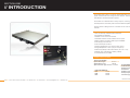
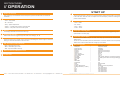
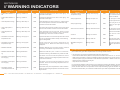
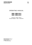
USER MANUAL
919 E. 29th St. Lawrence, KS 66046 // tel: 1-800-255-0247 // fax: 785-841-9512 // email: [email protected] // www.taikan.com
version: 062614
1550nm Transmitter
OT-860-1550-xx-SA-x-x
Please read this manual thoroughly before use.
Retain this manual for future reference.
Taikan 1550nm Transmitter Owner’s Manual
This manual is intended for use by purchasers of Taikan’s 1550 family of transmitters and their qualified technicians. This
document is the property of Taikan Company Inc. (“Taikan”) and embodies proprietary subject matter.
All design, manufacture, reproduction, use and sale rights regarding these products are expressly reserved.
This manual may not be reproduced without written consent from Taikan.
All copyright, patent and trade secrets for this manual and product are expressly reserved by Taikan. Specifications are also
subject to change without notice.
SAFETY PRECAUTIONS
> Read the user manual carefully before proceeding with any part of the installation.
> Installation and operation of the product must be performed only by qualified personnel and always in accordance with applicable
electrical codes.
> All warnings on the product and in the operating instructions should be adhered to.
> Unplug the product from the power outlet before cleaning. Do not use liquid or aerosol cleaners. Use a damp cloth. For the optical
connector it is recommended that you use RIFOCS CO. , Ltd’s 945/946.
1550nm Optical Transmitter units may emit harmful laser radiation
when the product is powered on or when the case is opened.
> Do not block or cover openings . These are provided for ventilation and protection from overheating. The maximum operating
temperature is 50°C (122 °F)
> This product should be operated only from the type of power sources indicated on the marking label.
> This product may be equipped with a polarized AC line plug (a plug having one blade wider than the other or a different shape).
This plug will fit into the power outlet only one way. This is a safety feature. If you are unable to insert the plug into the outlet, try
reversing the plug. Contact your electrician to replace the obsolete outlet if this still does not work. Do not compromise the safety
purpose of the polarized plug.
> For added protection during a lightning storm or when the equipment is left unattended or unused for long periods, unplug it from
the power outlet and disconnect the cables between the equipment and the fiber subsystem. These precautions will prevent
damage to the equipment that could be caused by lightning strikes or power line surges.
> Do not attempt to service this equipment yourself as opening or removing the cover may expose you to dangerous voltages or
other hazards. Refer all servicing to Taikan Company. A Taikan representative can be reached at [email protected]
Please be cognizant of all safety guidelines and
adhere to the recommendations listed.
If any parts need to be replaced notify a Taikan representative at [email protected]
> Unauthorized alteration or inappropriate repair is NOT allowed and may cause irreparable damage to product. Taikan does not
assume any responsibility for these modifications.
Taikan // 919 E. 29th St. Lawrence, KS 66046 // tel: 1-800-255-0247 // fax: 785-841-9512 // email: [email protected] // www.taikan.com
1550nm Transmitter | 03
TABLE OF
CONTENTS
Preface
01
Safety Precautions
03
Introduction
07
Product Summary
Standard Features
Nominal Specifications
Installation
08
Unpacking
Static Sensitivity
Power Supply Condition
Placement of the Transmitter
Electrical Connection
RF Connection
Optical Connection
Operation
10
Operation
Start Up
Adjustments
12
OMI
AGC
MGC
Network Setup
13
Warning Indicators
14
Warning Indicators
Possible Resolutions
Return & Warranty
16
Product Return Procedure
Standard Taikan Product Warranty
Taikan // 919 E. 29th St. Lawrence, KS 66046 // tel: 1-800-255-0247 // fax: 785-841-9512 // email: [email protected] // www.taikan.com
1550nm Transmitter | 05
SECTION ONE
// INTRODUCTION
PRODUCT SUMMARY
The OT-860-1550-xx-SA-x-x (a 1550 nm optical transmitter) converts RF cable signals to fiber
signals, and distributes them throughout a HFC network. This unit is primarily used in upgraded
cable television and fiber distribution systems.
The OT-860 unit is available with a variety of options, including automatic gain control, laser
overheat protection, automatic power control and advanced prediction distortion circuit.
Each transmitter is designed to fit in a standard 19 inch rack and can support up to 77 NTSC
channels.
STANDARD FEATURES
• 1550 nm externally modulated optical transmitter
• RF bandwidth: 54–860 MHz
• Headend 19 inch rack mount enclosure
• LED status and alarm monitor indicators on front panel
• Network interface port: RJ45, R232 support IE & SNMP
• Power Supply of 110~250 Vac
• Power Consumption of ≤50 W
• Operating Temperature of 0°C (32°F) to 65°C (149°F)
• Storage Temperature of -20°C (-4°F) to 70°C (158°F)
• Dimensions (LxWxH) of 483 x 385 x 44mm (19 x 14 x 1.75 in)
• DFB laser type. Laser Range 5~9 dBm (4~8mW)
• Front Panel RF test port -20dB
NOMINAL SPECIFICATIONS*
OPTICAL FEATURES
Optical Wavelength:
1550 nm
Optical Return Loss:
≥ 60 dB
Optic Connector Type: SC/APC or FC/APC
LINK PERFORMANCE
Taikan // 919 E. 29th St. Lawrence, KS 66046 // tel: 1-800-255-0247 // fax: 785-841-9512 // email: [email protected] // www.taikan.com
RF FEATURES
RF Bandwidth:
54-860 MHz
RF Input Level:
23 dBmV
RF Flatness:
≤ ± 0.75 dB
> 16 dB
CNR:
≥ 52 dB
RF Return Loss:
CTB:
≥ 65 dB
RF Input Impedance: 75 ohm
CSO:
≥ 65 dB
Connector Type:
F type
* Specifications and features are subject to change without notice
1550nm Transmitter | 07
SECTION TWO
// INSTALLATION
1
UNPACKING
4
Carefully open the package and adhere to all safety guidelines outlined in the safety section.
TRANSMITTER PLACEMENT
The transmitter is designed to fit in an EIA standard 19-inch (480 mm) equipment rack.
Check the packaging material for the following components.
> 1550nm optical transmitter
When placing the unit inside the rack, we recommend leaving one open slot (approximately 1
> User Manual
3/4”) between each unit. Doing so allows for cooling. From the front of the rack, cover any open
> Test Report
slots with a blank plate to minimize the risk of dust entering the rack.
> Power Cord
It is recommended that the transmitter be placed in an environment that maintains a temperature
of approximately 25° C (77°F).
It is highly recommended that the cover be left on the optical connector until you are ready to install the transmitter
into the headend rack. Not complying could “pollute” the connector thereby compromising the transmission quality.
The side effects include:
5
ELECTRICAL CONNECTION
The transmitter should have good grounding with a resistance <4 ohm. According to the interna-
> Decrease in analog signal transmission quality
tional standard, the 220 V plug in adopts tri-wire rule, while the middle wire is the grounding wire.
> Increased incorrect data rate for the digital signal
> Decrease in optical power
> Optical receiver’s optical power is compromised
The transmitter’s power supply has overflow protection. It can work with a 110~254 VAC electric
> Pollution of the other optical components
network, while the microprocessor monitors the output DC voltage.
Please notify your Taikan representative ([email protected]) if any of the items appear lost or damaged.
2
STATIC SENSITIVITY
When opening or operating the product, please comply with standard static protection procedure,
Prior to connecting the circuit, use the electric wire (#20 AWG or >) to connect the grounding screw on the bottom to
the grounding frame. When using the DC input power supply, the equipment chassis must be grounded.
such as using a grounding metal wrist belt, grounding worktop & grounding conductor.
NOTE TO CATV SYSTEM INSTALLERS: This reminder is provided to call your attention to NEC Articles 810- 21, 82022, and 820-40 that provide guidelines for proper grounding. In particular, these articles specify that the cable ground
shall be connected to the building grounding system, as close to the point of cable entry as practical.
Adhering to these guidelines will minimize the risk of damaging the product.
6
3
RF CONNECTION
POWER SUPPLY CONDITION
Connect the RF cable & the connector on the transmitters rear panel. The RF Connector is a
The transmitter is powered by AC or steady voltage DC.
F type plug with a resistance of 75 ohm.
> AC Input:
94-245 VAC, 50-60 Hz
> DC Input:
36-60 VDC, floating
> Power Consumption:
Maximum 50 W
7
OPTICAL CONNECTION
Connect the output fiber optic jumper to the proper input connector socket. The connector types
are FC/APC, E-2000, pigtail or SC/APC.
Taikan // 919 E. 29th St. Lawrence, KS 66046 // tel: 1-800-255-0247 // fax: 785-841-9512 // email: [email protected] // www.taikan.com
1550nm Transmitter | 09
SECTION THREE
// OPERATION
START UP
1
2
ON/OFF KEY BUTTON
Turn the optical power on from the front panel On/Off key. Wait a few seconds for the transmitter
to do a self check. After the check is complete the screen will display a welcome message with the
STATUS INDICATOR ( A GREEN LIGHT DENOTES ACTIVITY)
product model indicated.
2
> Laser – Green
> Temp – System temperature
> RF – Green
> Power 1 – Furthest power outlet on the back panel
> Temp. – Green
> Power 2 – 2nd power outlet on the back panel
> Power – Green
DISPLAY
3
6
4
ACCESSING THE SUB MENU
To access the Sub Menu stop on the main menu topic you would like to view and press the
Press the button once to toggle through the various subcategories. Press it again to select the
‘Select’ button.
setting you would like and return to the main menu.
To exit out of the Sub Menu press the select button a 2nd time. Please note that pressing the
‘Select’ button a second time saves the changes you have made.
OMI, AGC & MGC STATUS INDICATOR
> MGC – Modulation gain control
> OMI – Optical modulation intensity
8
options listed on the next page.
SELECT BUTTON
> AGC – Automatic gain control
7
ACCESSING THE MAIN MENU
To access the Main Menu, use the arrow buttons on the front panel and toggle through the
DIRECTIONAL ARROWS
Select these buttons to toggle through each main menu category. ▲ ▼
5
STATUS LAMPS SHOULD REFLECT THE FOLLOWING
> RF – RF status
LCD displays selected menu items and warnings.
4
TURN ON THE POWER SWITCH ON THE REAR PANEL
transmitter.
> Laser – Laser status
3
1
After powering on the transmitter from the back panel, press the On/Off button to activate the
MODULATION DEPTH INDICATOR LIGHT
RF TEST PORT
Taikan // 919 E. 29th St. Lawrence, KS 66046 // tel: 1-800-255-0247 // fax: 785-841-9512 // email: [email protected] // www.taikan.com
5
MENU DEFINITIONS*
> Main Menu
> Descriptor
> Serial Number
> Model Number
> Output 1
> Output 2
> LD S/N
> Laser Current
> Laser Temperature
> TEC Current
> RF Mode
> OMI Adjust
> RF Level
> SBS
> SBS State
> CSO State
> Date
> Version
> System Temperature
> Voltage Monitors (5,-5,24V)
> IP
> Sub
> GW
> TR1
> TR2
–
–
–
–
–
–
–
–
–
–
–
–
–
–
–
–
–
–
–
–
–
–
–
–
–
Default Description
Equipment model
438292F
10020476
Displays current output
Displays current output
204188
00mA
24.6 °C
0.09 A
AGC (press ‘Select’ to change and toggle through the options)
0.5 dBm (press ‘Select’ to change and toggle through the options)
OK
OK
OK
OK
Displays date
08.05
Reflects current temperature
-5, 5, 24V
192.168.000.012
255.255.255.000
192.168.000.001
192.168.006.144
192.168.006.144
*Information above is for reference only. The data will vary by unit.
1550nm Transmitter | 11
SECTION FOUR
SECTION FIVE
// ADJUSTMENTS
// NETWORK SETUP
ADJUSTING THE OMI
Note: The default OMI is set at AGC status.
The Optical modulation intensity (OMI) is set at the optimal level at the time of production. The
“Modulation Depth” indicated on the front panel displays at the NOM position. The NOM position
refers to the Modulation Depth when the full channels are loading, or when the system CNR ≥ 53 dB.
Increasing the OMI value, will result in the following:
> CNR – Increases > CTB & CSO – Decreases
Decreasing the OMI value, will result in the following:
> CNR – Decreases > CTB & CSO – Increases
NETWORK SETUP
Taikan’s 1550 Transmitter is designed to be compatible with an EDFA amplifier. The following factors
should be taken into consideration when doing so:
• Chromatic Dispersion
• SBS
• SPM (Self Phase Modulation)
• Other non linearity effects of fiber optics
SETTING AGC STATUS
Please note that the OMI is set at an optimal level and it is recommended that the value not be
adjusted.
CHOOSING THE APPROPRIATE SBS VALUE
To transmit more than 100km, you need to select 13 dBm SBS restrain status. 13dBm restrain
status should be selected because of SPM and optic fiber chromatic dispersion. Not extending
the bandwidth status when the fiber length is longer will compromise the transmitters CSO performance. A smaller line bandwidth should be selected for longer distances. The following table
shows the recommended fiber lengths for each SBS restraint status.
ADJUSTING OMI UNDER AGC STATUS
I. Press the arrow button on the front panel until ‘OMI Level’ displays on the screen.
II. Press the ‘Select’ button and toggle through the menu using the arrow button to verify the
current OMI status.
If the display shows RF Mode = AGC, then the unit is under AGC status
If the display shows RF Mode = MGC, then the unit is under MGC status
III. To change the status to AGC follow these steps.
Press the ‘Select’ button to enter the subcategory, to display RF Model=
Press the ▲ Directional Arrow to confirm RF Mode = AGC. AGC is now complete.
SETTING MGC STATUS
I. Press the arrow button until the display shows the OMI Level Menu
II. Press the ‘Select’ button to enter the sub menu and toggle through with the arrows until it
plays OMI ADJ= + X
III. Toggle through with the arrow button until you find the appropriate value. The values
are in increments of 0.3 dB.
IV. Press the ‘Select’ button again to confirm the OMI value.
Outlined below are some simple rules for your reference:
Optical Fiber Length
< 60 km
< 70 km
< 120 km
> 120 km
SBS Restrain Condition
13 dBM, 16 dBm, 18dBm
13 dBm, 16dBm
13 dBm
13 dBm (CSO performance may vary)
SBS RESTRAINT VALUES
The table below shows the limit values for the corresponding SBS restraint power.
dis-
ADJUSTING MGC STATUS
I. Press the arrow button until OMI Level appears on the display.
II. Press the “Select’ button to enter the sub category and toggle through with the arrow button to
display the RF Mode = AGC
III. Press the arrow button to confirm , RF Mode= manual
IV. MGC has been successfully set
I. Confirm that the RF Mode=MGC
II. Gently place a ‘-’ screwdriver into the OMI adjusting hole. Carefully adjust the OMI to the NOM
position. You will know when it is in the NOM position when the two green lamps turn on. At this
point the RF status will turn from red to green.
SBS Restraint Power
18 dBm
16 dBm
13 dBm
Optic Fiber Input Power Limit
Max 18.4 dBm
Max 16.4 dBm
Max 13.4 dBm
Please note that if the power is greater than the stipulated limit, it will result in the following:
> Lower frequency band will have 1/f noise
> The CNR will be compromised on lower channels
> HUM is also compromised
ADJUSTING SBS VALUES
The default SBS restraint value is 16.5 dBm. To adjust this value follow these steps:
I. Press the arrow button, and select ‘SBS Menu’
II. Press the “Select’ button and toggle through the options using the arrow button. Select “SBS=16.5”
III. Press the ‘Select’ button, to begin selecting the desired “SBS” value
IV. Use the arrow button to select the required SBS critical value
V. Press the ‘Select’ button again for confirm
Taikan // 919 E. 29th St. Lawrence, KS 66046 // tel: 1-800-255-0247 // fax: 785-841-9512 // email: [email protected] // www.taikan.com
1550nm Transmitter | 13
SECTION SIX
// WARNING INDICATORS
TRANSMITTER WORK
LED COLOR
EXPLANATION
TRANSMITTER WORK
Warning: Lsr Bias Low
RED
Predicts the deflected circuit fault or laser aging. The
transmitter needs repair.
STATUS
> Transmitter interface board
temperature is high
> Present laser deflection is
high
Warning: Lsr Bias Hi
RED
Predicts the deflected circuit fault or laser aging. The
transmitter needs repair.
> Laser temperature is high
Warning: Laser Temp Hi
STATUS
> Present laser deflection is
low
STATUS DISPLAY
> Laser output power is
locked
Warning: Laser Pwr Lock
> Laser temperature is
locked
Warning: Laser Temp Lock
RED
RED
RED
EXPLANATION
Warning: Amb temp high
RED
Transmitter inner panel temperature is close to limitation. Check the surrounding temperature and continue to
monitor the device.
> RF Input gain is low
Warning: RF Input Low
RED
RF input gain is close to minimum value of AGC. Check
the input gain & route. Continue monitoring
> RF Input gain is high
Warning: RF Input Hi
RED
The input gain is close to the maximum value of AGC.
Check the input gain & route. Continue monitoring the
device.
The laser output power has moved from the correct value
but the circuit is locked. Continue to monitor the situation.
> AGC circuit is not locked
Warning: AGC Not Locked
RED
Laser temperature control loop fault. Check the room
temperature and confirm whether it is still in the recommended range. Continue to monitor the situation.
RF input gain is close to margin. Adjust the input gain to
eliminate the warning. If the warning light remains on,
return the transmitter for repair
> Fan fault
Warning: Fan Failure
RED
The rear fan is faulty. The transmitter needs to be
repaired.
Optical transmitter environment temperature has moved
from 25 °C. Monitor the situation closely until the warning
light has disappeared.
> Modulator drive gain is low
Warning: OMI Low
RED
The RF drive power entering the modulator is low. The
CNR performance can be improved by increasing OMI.
> Modulator drive gain is
high
Warning: OMI Hi
RED
The RF drive power entering the modulator is high. The
distortion performance can be improved by decreasing the
OMI.
> Transmitter environment
temperature is low
Warning: 1 temp (12) Lo
> Transmitter environment
temperature is high
Warning: 1 temp (12) Hi
RED
Optical transmitter environment temperature has
moved from 25 °C. Monitor the status until the warning
disappears.
> Modulator deflected
Warning: Modulator Bias
RED
Modulator deflection point is close to maximum. Continue
monitoring. The deflection may need to be reset.
> Modulator deflection floating
Warning: Mod Drift Hi
RED
LED COLOR
Laser temperature is hovering from 25 °C. Check whether
the room temperature is still in the recommended range.
Continue to monitor the situation.
RED
Modulator deflection point is close to the maximum.
Continue monitoring. The deflection may need to be reset.
> Transmitter inner temperature is high (1)
Warning: 1 temp (L)
RED
Transmitter inner environment temperature is close to
limitation. Check the surrounding temperature and continue to monitor the device.
> Transmitter inner temperature is high (2)
Warning: Code #13c
RED
Transmitter inner environment temperature is close to
limitation. Check the surrounding temperature and continue monitoring.
> Transmitter interface
board temperature is low
Warning: Amb temp low
RED
Transmitter inner panel temperature is close to limitation.
Check the surrounding temperature and continue monitoring the device.
STATUS DISPLAY
POSSIBLE RESOLUTIONS
I. Some of the warnings stated above can be resolved by restarting the power supply or pressing the “On/Off’ button on the front
panel. Please notify your Taikan representative if the warning indicator is still on.
II. To prevent any type of warning please follow these setup requirements:
> Ensure that the transmitter is placed in a temperature controlled environment of 0 °C ~ 50° C, that is also dust free.
> Make sure the transmitter is properly ventilated and allow ample space for the rear fan to work
> Check the power supply to confirm that it meets standard requirements. In addition check all connections are secure.
> Double check the changing of the RF gain.
> Keep the fiber connector clean.
III. The modulator deflector voltage warning can be resolved by resetting its deflection. To reset the deflection, press the “On/Off”
button and press it again to turn it on. It will take approximately 45 minutes for the transmitter to return to stable status. During this
period, the CSO value will be compromised, and the output and floating signal will decrease. This step should be carried out at a
time that would least affect your subscribers. Please contact your Taikan representative if this still does not resolve the situation.
Taikan // 919 E. 29th St. Lawrence, KS 66046 // tel: 1-800-255-0247 // fax: 785-841-9512 // email: [email protected] // www.taikan.com
1550nm Transmitter | 15
SECTION
SECTIONSEVEN
SEVEN
//// RETURN
RETURN &
& WARRANTY
WARRANTY
PRODUCT RETURN PROCEDURE
If you need to return the product for repair, please follow these steps:
1. Contact a Taikan Representative at [email protected] to obtain a Return
Authorization Number
2. When returning the product for repair include the following information:
> Return Authorization Number
> Model Number
> Serial Number
> Reason for Return
3. Prior to repairing the device, Taikan will inform you about the test results and/or any additional
repair charges that may apply. Once we have received your confirmation we will proceed
with the repair.
4. The repair period will depend on the severity of the problem.
5. After it is returned, the product will still be under its original warranty. The repair
component(s) is under warranty for 90 days after you have received the repaired product.
(see below)
STANDARD TAIKAN PRODUCT WARRANTY
Taikan provides a limited three year Warranty (“Warranty”) to original purchaser on its product
against manufacturing defect and workmanship under normal use and service. During the Warranty period Taikan will repair or replace the product to correct defects in material and workmanship.
This Warranty shall not apply to a product which has been altered in any way so as to affect its
stability or durability, nor which has been subject to misuse or negligence. This Warranty does not
cover a product which has been damaged by severe weather conditions such as extreme wind,
ice, storms, lightning, or other natural weather conditions over which Taikan has no control.
Claimants under this Warranty shall present their claim along with the defective product to Taikan
Non-compliance with any part of this claim procedure may invalidate this Warranty in whole or
part.
This Warranty is expressly in lieu of all other agreements and warranties, expressed or implied.
Taikan does not authorize any person to assume for it the obligations contained in this warranty
and neither assumes nor authorizes any representative or other person to assume for it any other
liabilities in connection with the product delivered or provided.
In no event shall Taikan be liable for any loss of profits, loss of use, interruption of business, or
indirect, consequential damages of any kind. Taikan will not be liable for damages in any amount
greater than the purchase price of the product.
Taikan // 919 E. 29th St. Lawrence, KS 66046 // tel: 1-800-255-0247 // fax: 785-841-9512 // email: [email protected] // www.taikan.com
1550nm Transmitter | 07