1
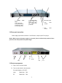
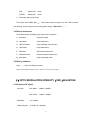
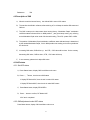
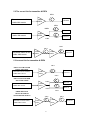
1550nm TRANSMITTER
1550 nm EXTERNAL MODULATION
CATV OPTIC TRANSMITTER
USER MANUAL
Quality Cable and Electronics • 1780 N.W. 15th Avenue Suite 400 • Pompano Beach, FL 33069
Tel: (954) 978-8845 • Fax: (954) 978-8831 • www.qualtiycable.com • Email: [email protected]
DECLARATION
Our Company describes the manual of 1550nm external
modulation transmitter 2X3 dBm roundly precisely & in latest
edition. But we apprizes clients prudently that our company
reserves the authority to adjust the relevant content in the file. We
will not take the responsibility for the result from the mistake of
recommended material, printing & tabling.
This manual states the shape, function, installation, network
application and all the acceptable standard options of 1550nm
External modulation CATV optic transmitter 2X3dBm. Includes
following items:
y
SYSTEM INSTALLATION
y
SYSTEM OPERATION
y
SYSTEM DEBUGGING
y
NETWORK DESIGN
y
OPERATION PRINCIPLE
y
FAULT DISPOSAL FLOW
y
RETURN FOR REPAIR
1
CONTENT
Ⅰ. Product summary………………………………………………………………………………………4
1.1 Product summarize …………………………………………………………………………………4
1.2 Product specialty……………………………………………………………………………………4
1.3 Technique index ……………………………………………………………………………………4
Ⅱ.
Installation
…………………………………………………………………………………………5
2.1 Goods receipt checking
…………………………………………………………………………5
…………………………………………………………………………… 5
2.2 Installation notice
2.2.1 Safety factor
……………………………………………………………………………… 5
2.2.2 Static sensitivity specialty
2.3 Installation preparation
…………………………………………………………………6
……………………………………………………………………………6
2.3.1 Environment condition ………………………………………………………………………6
2.3.2 Power supply condition………………………………………………………………………6
2.4 Equipment setting …………………………………………………………………………………7
2.5 Electric connection ………………………………………………………………………………… 7
2.6 RF connection
……………………………………………………………………………………7
2.7 Optic connection ……………………………………………………………………………………7
Ⅲ.
Operation
……………………………………………………………………………………………8
3.1 Front panel control & indicator ……………………………………………………………………8
3.2 Rear panel connection ……………………………………………………………………………9
3.3 Boot-strap Sequence………………………………………………………………………………9
3.4 Startup main menu
………………………………………………………………………………10
2
3.5 Startup sub menu
Ⅳ. (OMI)adjusting
…………………………………………………………………………… 10
…………………………………………………………………………………10
4.1 Request for RF signal……………………………………………………………………………10
4.2 Request for RF signal……………………………………………………………………………10
4.3 AGC status
…………………………………………………………………………………11
4.3.1 AGC status setup
4.3.2 AGC status adjusting
…………………………………………………………………… 11
………………………………………………………………… 11
………………………………………………………………………………… 11
4.4 MGC status
4.4.1 MGC status setup
…………………………………………………………………… 11
4.4.2 MGC status adjusting …………………………………………………………………… 12
Ⅴ. Network design ………………………………………………………………………………………12
5.1 SBS critical value ‘s choice …………………………………………………………………… 12
5.1.1The longest optic fiber distance of system transmission …………………………… 12
5.1.2 Fiber input optic power……………………………………………………………………12
5.2 Correct connection between TX & EDFA ……………………………………………………13
5.3 Incorrect connection between TX & EDFA ……………………………………………………13
5.4 SBS adjustment process ……………………………………………………………………… 14
Ⅵ. Equipment working principle
Ⅶ.
……………………………………………………………………14
Fault disposal ……………………………………………………………………………………… 15
7.1 Warning status
7.2 Alarm status
………………………………………………………………………………… 16
…………………………………………………………………………………… 17
7.3 Fault precaution
……………………………………………………………………………… 17
3
7.4 Deflection restoration …………………………………………………………………………… 17
7.5 Sensitivity degree to 980 nm laser ………………………………………………………………17
Ⅷ. Guaranteed repair range for product
8.1 Guaranteed repair rule
……………………………………………………………18
………………………………………………………………………18
8.2 Instruction for special product guarantee & repair ………………………………………………18
8.3 Compensation range
……………………………………………………………………………18
Ⅰ. PRODUCT SUMMARY
1.1 Product summarize
1550nm External Modulation CATV transmitter 2X3dBm adopts low noise, narrow bandwidth, and
continuous wave laser as its light source. It uses high linearity LiNbO3 external modulator to
modulate signal. It eliminates the Chirp Effect of 1550nm direct modulation laser. Due to adopting
owned system optimized control technology & using top grade key parts, the machine’s technique
performance index achieves the standard of same advanced products in the world totally.
1.2 Product specialty
1. High index:Original system optimized control technology, offers excellent CNR, CTB, CSO & SBS
index.
2. Flexibility:Original SBS critical value 13, 16, 18 adjustable at spot, it can fit for different network.
3. Reliability:Inside double power supplies, switch automatically. Machine case temperature control
automatically.
4. High quality:Intuitionistic Optic Modulation Intensity(OMI)display.
4
1.3 Technical index
Performance
Wavelength range
(nm)
Line width
Side mode suppression ratio
Optic
Equivalent noise intensity
feature
1555±5
ITU-TG.692 Standard wavelength
≤1
FWHM(△λ)
(dB)
≥45
SMSR
≤-160
RIN (20~1000MHz)
2×3
Optional 2×5, 2×6, 2×9, 2×10
(dBm)
Return loss
(dB)
≥50
SC/APC
Optical fiber connector
Work bandwidth
Input level
RF
feature
(MHz)
47-862
(dBmV)
18~28
AGC
(dB)
≤±0.75
45~862MHz
Return loss
(dB)
>16
45~750MHz
(Ω)
75
F-Female
RF port
Transmit channel
feature
PAL-D/60CH
(dB)
≥53
Back to back
CNR2
(dB)
≥52
65Km optical fiber, 0dBm receive
CTB
(dB)
≤-65
CSO
(dB)
≤-65
(dBm)
Network interface port
feature
NTSC/80CH
CNR1
SBS restrain
General
Optional LC/APC,FC/APC
Flatness
Input impedance
Link
Supplement
(MHz)
(dB/Hz)
Output power
Index
13, 16, 18
Adjustable
RJ45, RS232
Support I.E. & SNMP
Power supply
(V)
220VAC
-48VDC optional
Power Consume
(W)
≤50
Single power works
Work temp.
(℃)
-5~65
Storage temp.
(℃)
-40~85
Operating relative humidity
(%)
5~95
(")
19×14.5×1.75
Size
Machine temp. control
automatically
(W)x(D)x(H)
Ⅱ. INSTALLATION
In installation equipment, please execute as following process. Every detail of installation will be
described in this chapter. This chapter includes main contents as below.
y Checking the possible loss or damage of the equipment in transportation.
y Prepare the executive setting environment
y Setting 1550nm optic transmitter
5
y Electric connection
y RF signal connection
y Optic connection
y Network connection ports
2.1 Checking goods in receiving
Carefully open the packing to check the machine & parts. Please check the packing material of small
parts also. Checking the objects as below items.
y 1550nm optic transmitter
y User operation manual
y Test datum of leaving factory
y Alternating power supply plug wire
If any item lost or damaged, please inform us immediately.
2.2 Installation notice
2.2.1 Safety factor
When install & use the products, please accord with all the relative safe measure of management &
operation. If disobey below stated safety measure & special steps in the manual, it will damage the
safe grade in product design, production & expected purpose. Our company will not take any
responsibility for the result from user disobeying safety measure. Please notice the content with the
below sign ; if ignore it, will bring damage to equipment & parts possibly.
WARNING
Don’t operate it before you understanding & realizing all the conditions exactly!
2.2.2 Static sensitivity spatiality
Please obey static protection process and operate it.
Operating according to design request totally, the semi-conductor optic transmitter & receiver have
high reliability performance. But, the static result from careless operating will damage the
semi-conductor transmitter possibly.
Static can pass through the rear panel connector or front panel test ports into the semi-conductor
transmitter. When opening or operating the transmitter, please accord with Static Protection
Procedure, including using grounding metal wrist belt, grounding worktop & grounding conductor.
If place the optic transmitter on the ground, the static charge will mostly decreased.
6
2.3 Installation preparation
2.3.1 Environment conditions
According to the design request, 1550nm optic transmitter can work under 0℃~50℃(32℉~122℉)
temperature range. We recommend 25℃(77℉)environment temperature.
Humidity not bigger than 95 %(under non-coagulation condition). If necessary, the equipment
should keep the suitable temperature & humidity in the restrained scope. We recommend to
operating in the environment without dust.
2.3.2 Power supply condition
Equipment powered by AC or steady voltage DC. In both of AC & DC, AC is the chief power supply.
Request of power supply:
AC input
94-245 VAC,50-60 Hz
DC input
36-60 VDC ,floating
Power consumption
Maximum 50 W
The DC power supply of the equipment must be the SELV supply stipulated as CAN/CSA
C22.2 No.950-95 standard.
2.4 Equipment setting
1550nm optic transmitter adopts 1U high,Standard 19″casing. We suggest to keeping 1.75-inch
(about 4.5cm) space on the top & bottom of the machine, to ensure the ventilation & heat dispersion.
2.5 Electric connection
(1) The machine should have good grounding, grounding resistance < 4 Ω . According to the
international standard, 220V plug in adopts tri-wire rule, the middle wire is the grounding wire.
(2) The machine adopts high performance, high reliability, steady voltage switch power supply, it has
isobaric ally overflow protection. It can work in 110~254 VAC electric network. The micro processor
are monitoring the output DC voltage. If the Fuse is melted broken, it shows the machine’s inner parts
has occurred problems.
WARNING
7
Before connecting circuit, please use big spec (#20AWG and more) electric wire to connect the
grounding screw on the bottom and the grounding frame. When use DC input power supply, the
equipment chassis must be grounding.
2.6 RF connection
Connect the RF cable & the connector on TX rear panel. RF connector is F type plug. The equipment
uses Britain System. The resistance is 75Ω.
2.7 Optic connection
Considering for protection & safety, all the fiber optic connector need protect cover in transportation.
Don’t take away the protect cover before setting.
In order to ensure the insertion loss & return loss, the end-face of fiber optic connector is polished
extremely. Please don’t dirt the pollute the connector. Even very micro dust will also affect the
transmission quality. When off the fiber optic connector, please put on the protection cover.
To keep the cleaning of fiber optic connector in connection or re-connecting is very important.
Without proper maintain job, fiber optic transmission system will not realize the function very perfectly.
The system function will be decreased as below forms
y
Analog signal transmitting quality turns bad
y
Digital signal wrong data rate will increase
y
Optic power will be decreased.
y
Optic receiver’s receipt optic power cannot reach the best range.
y
Dusty fiber optic connector will pollute other connected optic parts.
Recommended RIFOCS Co., Ltd ’s 945/946 fiber optic cleaning system to clean the connectors. For
the covered optic fiber connector, please discharge the rear panel then pull out the inner optic jumper
and clean it.
WARNING
Cleaning all the fiber optic connectors before setting.
Connect the output fiber optic jumper into the proper input connector socket of EDFA.
connector type is FC/APC, E-2000, pigtail or SC/APC optional.
8
The
Ⅲ. OPERATION
3.1 Front panel control & indicator
1. Laser key switch
Laser source On/Off switch(Press to ON)
2. Status indicator LCD
①LASER
Laser status
②RF
RF status
③FAN
System temperature
④POWER
Power status
3. VFD display
Double line VFD display each parameter & warning
4. Choose button △, ▽
5. Status
Up/down/choice button
Choose main menu and set up working status & parameter
6. OMI modulation coefficient indicator
Indicate present OMI index
No RF input, 20 lamps all not turn on
2 pcs green lamps on (in 20 pcs lamps) indicates OMI suitable
(as original status of leaving factory)
7. AGC status indicator
This lamp on, it is in AGC status
8. MGC status indicator
This lamp on, it is in MGC status.
9. OMI adjusting
This function for user application
--
In AGC status, OMI value adjustable slightly
① Key switch
Accord with IEC
safety standard ;
Protect radiation to
the user’s bare skin..
③
Display
Layered
menu,
controlled by front
buttons. Monitor &
control the selected
parameter.
In MGC status, OMI value adjustable
⑤
Select
Select one item from
the menu to observe Modulation
and adjust it.
Depth
Indicator
9
⑩
RF test port
For inspect of input
signal
②
Lighting
④
diode
Up/Down button
⑨
Guide user for
checks the menu
and adjusts the
parameter.
status
1.Laser status lamp
2.RF input status lamp
3.Casing temp. status
4.Power supply status
OMI adjust slightly
⑧
MGC
indicator
status
⑦
AGC
indicator
status
3.2 Rear panel connection
Power supply input module consists of “On/Off”switch , adopts 3-pin IEC AC plug-in.
Notice: Before turn on the power supply in rear panel, please confirm the key switch of front
panel is on the ‘Off’ position. Rear panel image:
RS232
FAN
FAN
3.3 Boot-strap sequence
A、 Plug in 220V city power supply
B、 Turn on power switch in the rear panel
Front panel display “ KEY OFF”
Laser
Status lamp
Red
RF
Status lamp
Red
10
powers
FAN
Status lamp
Green
POWER
Status lamp
Green
C、 Press laser start-up key switch
Front panel shows “KEY ON……”,Laser status lamp turns green from red, machine enters
self-checking, after checking it enters working status, display “ Welcome to……。”
3.4 Start-up main menu
Press Status button will display below main menu in sequence.
A、 Descriptor
Equipment model
B、 Optic Menu
Optic status menu
C、 OMI Level Menu
Optic modulation intensity menu
D、 Laser Menu
Laser status menu
E、 SBS Menu
SBS restrain status menu
F、 Modulation Menu
External modulator status menu
G、 Stem Menu
System parameter menu
3.5 Start-up submenu
Press △、▽ button will display submenu.
When screen displays submenu, press “ Status” will not work any longer.
Ⅳ. OPTIC MODULATION INTENSITY(OMI)ADJUSTING
4.1 Request to RF signal
Input gain:
Bandwidth:
AGC status
78dBμV~88dBμV
MGC status
75dBμV~85dBμV
45~862MHz
Flatness degree: ±0.75dB(45~862MHz)
11
Resistance:
75Ω
4.2 Description of OMI
A、 When the machine leaves factory,the default OMI is set on AGC status.
B、 The machine has Build-in software, after switching off, it will keep the earlier OMI status and
OMI set.
C、 The OMI is setup on the best status when leaving factory, “Modulation Depth” modulation
coefficient status indicator will be on NOM position , ( two green lamps turning on), referring
to the Modulation Depth when under full channels loading, TX to RX, system CNR ≥53Db.
D、 The position of Modulation Depth modulation coefficient status indicator lamp is determined
by the needed Modulation Depth, if it is in NOM position has nothing to do with any default of
the whole unit.
E、 Increasing OMI value, CNR will be up,but CTB、CSO value will be down. On the contrary,
decreasing OMI value, CNR be down, CTB、CSO value will be up.
F、 If not necessary, please don’t adjust OMI value.
4.3 AGC status
4.3.1 Set AGC status
A、Press Status button, display OMI Level Menu main menu
B、Press △、Vbutton, check current OMI status
If display RF Mode=AGC, then the unit is under AGC status
If display RF Mode=MGC, then the unit is under MGC status
C、Press Status button, display RF MODEL=
D、Press △ button to confirm, RF Mode=AGC
AGC set is completed
4.3.2 OMI adjustment under AGC status
Press Status button, display OMI Level Menu main menu
12
Press △、Vbutton, display OMI ADJ= ±×.××
Press Status button, display OMI ADJ=.
Press △、Vbutton, 0.3 dB step length, choose the proper value, such as OMI ADJ= +3.5dB。
Press Status Button, and confirm the OMI value.
4.4 MGC status
4.4.1 Set MGC status
A、Press Status button, display OMI Level Menu main menu
B、Press △、Vbutton, display RF Mode=AGC sub-menu
C、Press Status button, display RF MODEL=
D、Press △ button to confirm, RF Mode=manual
MGC set is completed
4.4.2 MGC status adjustment
Confirm RF Mode=MGC
Use slim “—“ type screwdriver into OMI adjusting hole, adjusting OMI, make Modulation Depth
( modulation coefficient indication )to NOM position, namely two green lamps turning on, this
time, RF status will turn from red into green.
The adjusted result should let CNR, CTB, CSO accord with system index.
Ⅴ. NETWORK DESIGN
1550nm system can use EDFA to extend transmission distance, when signal is operated in 1550nm,
the fiber should be considered of some factors, such as Chromatic Dispersion, SBS, SPM ( Self
Phase Modulation ) and other non-linearity effect of optic fiber. The network we designed for you has
supplied some simple rules of using the transmitter.
5.1 The choice of SBS critical value
5.1.1 The longest optic fiber distance in system transmission
If you want to transmit more than 100km, you need to select 13dBm SBS restrain status. Why you
need to do this is because of SPM & optic fiber Chromatic Dispersion. If bandwidth-extending status
is not changed, when fiber length is longer, CSO performance will be worse. If you want to choose
13
longer distance transmission, you need to select smaller line bandwidth. 13dBm is much smaller,
16dBm is much bigger, and 18dBm is the biggest. The following table shows the recommended fiber
length in which SBS restraint status.
Optic Fiber Length
SBS Restrain Condition
13dBm, 16dBm, 18dBm
<60Km
13dBm, 16dBm
<70Km
13dBm
<120Km
>120Km
13dBm(CSO performance will be some
different from the specification possibly)
5.1.2
The biggest optic fiber Input power is restricted by SBS restraint status. If your power is bigger than
the stipulated limit, it will occur some bad result. The low frequency band will have 1/f noise, low
channel’s CNR will not be good, HUM will also be worse than in normal status. The attached table
shows the limit value of SBS restraint power.
SBS restraint power
Limit of optic fiber input power
18dBm
Max.18.4dBm
16dBm
Max.16.4dBm
13dBm
Max.13.4dBm
The general CATV operator will use high power EDFA (such as 22dBm and higher one), and use
optic splitter to arrange the power transmitting in the optic fiber & cable. It is no problem to do this,
because the optic fiber patch cord is short. But it is necessary to notice that SBS restraint setup rest
with the worse situation, for example, the longest distance & the biggest fiber input power in the optic
cable.
14
5.2 The correct link for transmitter & EDFA
65Km
Transmitter rated at 65 Km,
16dBm SBS restraint
16dBm
EDFA
Receive
65Km
16dBm
Receiver
Transmitter rated at 65 Km,
16dBm SBS restraint
19dBm
EDFA
60Km
40Km
Transmitter rated at 65 Km,
13dBm SBS restraint
13dBm
EDFA
Receiver
65Km
16dBm
13dBm
EDFA
Receiver
5.3 Incorrect link for transmitter & EDFA
65Km
EDFA LAUNCH POWER
ABOVE SBS LIMIT
Transmitter rated at 100 Km,
13dBm SBS restraint
16dBm
EDFA
Receiver
65Km
EDFA LAUNCH POWER
ABOVE SBS LIMIT
Transmitter rated at 65 Km,
16dBm SBS restraint
19dBm
Receiver
22dBm
EDFA
Receiver
19dBm
65Km
FIBER DISTANCE
ABOVE MAXIMUM
TRANSMITTER RATING
Transmitter rated at 65 Km,
16dBm SBS restraint
60Km
40Km
13dBm
EDFA
13dBm
EDFA
15
Receiver
5.4 SBS adjustment process
1550nm External modulation transmitter 2X3dBm offers special technology. It can let user adjust the
SBS critical value at the spot. The default SBS restraint value is 16.5dBm when leaving factory. The
user can adjust it by himself. The adjustment process according to the real requirement of system:
A:Use STATUS button, select “SBS Menu” main menu;
B:Use △▽ button, select “ SBS=16.5” submenu ;
C:Press STATUS button, enter to opening “SBS” select software;
D:Use △▽ button,select the SBS critical value what you need;
E:Press STATUS button again for confirmation.
Ⅵ. EQUIPMENT OPERATION PRINCIPLE
1550 nm optic transmitter principle frame as picture 18 stated. Input RF signal is verified at AGC
circuit unit and affect on optic modulator to modulate the CW light, which is output from 1550nm laser
module. The small part output light is checked partly, then feedback to modulator circuit to control the
modulation gain & modulation distortion gain.
Picture 18. 1550 nm optic transmitter operation principle frame
16
The non-linearity of optic modulator is inherent. If there is no compensation, the distortion &
intercrossing modulation of modulator will let the signal cannot be applied. Generally, the inherent
distortion can be modified by adding DC deflected voltage on modulator crystal. For one more
modification, you can monitor the inter-modulation result of two low gain test signals, then adjust the
DC deflected voltage of modulator to decrease the distortion into the smallest value. These process is
in continuous execution under the closed loop control of system control microprocessor . It is clear to
user.
Microprocessor monitors the deflected gain for eliminating the distortion, and sending relative
warning. If any gain is close to the margin of control system, or the control system can not sustain the
deflection on the necessary gain, it will sending out warning.
The laser is placed on the Thermo-Electric Cooler (TEC) directly. Temperature control circuit drives
TEC working to control the working temperature of the laser , and prevent the performance
decreasing or damage result from overheated laser. The microprocessor monitors the temperature of
laser & controls the TEC current. If TEC current exceeds the pre-established standard range or is
close to the margin of control ability, the system will send out warning.
Setup the temperature warning can let the TX sustain the longest running time under the common
aging speed of the laser. And repair or replace the laser when it is necessary before the parts can not
be repaired.
Ⅶ. FAULT DISPOSAL
1550nm optic transmitter can monitor system operation and offer brief note of warning. It can correct
the majority status deflection of the equipment, such as : system parameter floating, equipment
tolerance, laser aging, RF gain changing, temperature changing. The TX will go on working when it is
sending out warning. The facility is self-detected continually and relative system parameter will
recover into normal range, then the warning will disappear. Some serious warning can be eliminated
by restart the power supply of the equipment. If some relative parameter recover to normal range, the
warning will disappear automatically.
The majority warnings will be sent out when the correction ability is close to or exceed the permitted
range. At most of these situation, user can not modify these status. Status modification needs special
equipment & available facility. The modification only could be processed in the factory.
7.1 Warning status
When TX is on warning status, the status LED will turn red and the brief note of status will be
displayed on the screen. The warning will not stop the TX running, it only shows the relative
parameter exceeding to normal scope slightly. If the warning is stopped, it shows the relative
parameter is returned into permitted scope. The screen & diode will return into their normal status and
no need to interfere by user. But to be emphasized is that the problem of warning can not be ignored.
It is possible of some serious system fault potentially.
TX work status
Status display
LED color
Explanation
17
Present laser deflection
Warning: Lsr Bias Low
Red
Predicts the deflected circuit fault or laser aging. The TX needs repair.
Warning: Lsr Bias Hi
Red
Predicts the deflected circuit fault or laser aging. The TX needs repair.
Laser temp. is high
Warning: Laser Temp Hi
Red
Laser temperature is floated from 25℃. Check the room temperature, whether it is still in
Laser output power is
Warning: Lsr Pwr Lock
Red
is low
Present laser deflection
is high
requested range. Continue monitoring.
locked
Laser output power is floated from correct value. But the circuit is locked. Please continue
monitoring.
Laser temp. is locked
Warning: Lsr Temp Lock
Red
Laser temp. control loop fault. Check the room temperature, whether it is still in requested
TX environment temp.
Warning: Itemp(12) Lo
Red
Optic TX environment temp. was floated from 25℃. Monitoring it till warning disappears.
Warning: Itemp(12) Hi
Red
Optic TX environment temp. was floated from 25℃. Monitoring it till warning disappears.
Warning: Modulator Bias
Red
Modulator deflection point is close to maximum. Continue monitoring. Deflection maybe
range. Continue monitoring.
is low
TX environment temp.
is high
Modulator deflected
need reset.
Modulator
deflection
Warning: Mod. Drift Hi
Red
floating
need reset.
TX inner temp. is high
Warning: Itemp(L)
Red
(1)
Warning: Code #13c
Red
(2)
TX inner environment temp. is close to limitation. Check the surrounding temperature and
continue monitoring.
interface
board
Warning: Amb temp low
Red
temp. is low
TX
TX inner environment temp. is close to limitation. Check the surrounding temperature and
continue monitoring.
TX inner temp. is high
TX
Modulator deflection point is close to maximum. Continue monitoring. Deflection maybe
TX inner panel temp. is close to limitation. Check the surrounding temperature and
continue monitoring.
interface
board
Warning: Amb temp high
Red
temp. is high
TX inner panel temp. is close to limitation. Check the surrounding temperature and
continue monitoring.
RF input gain is low
Warning: RF Input Low
Red
RF input gain is close to minimum value of AGC. Check the input gain & route. Continue
RF input gain is high
Warning: RF Input Hi
Red
RF input gain is close to maximum value of AGC. Check the input gain &
monitoring.
route.
Continue monitoring.
AGC
circuit
is
not
Warning: AGC Not Locked
Red
RF input gain is close to margin. Adjust the input gain to eliminate the warning. If the
Fan fault
Warning: Fan Failure
Red
TX rear fan parts is faulty. TX needs repair.
Modulator drive gain is
Warning: OMI Low
Red
The RF drive power entering modulator is low. CNR performance can be improved by
locked
warning is still existed. The TX needs repair.
low
increasing OMI.
Modulator drive gain is
Warning: OMI Hi
high
Red
The RF drive power entering modulator is high. Distortion performance can be improved
by decreasing OMI.
Picture16. Warning information
7.2
Alarm status
When the TX send out warning, it is stopped working generally. The alarm is because of some
relative parameter exceeding its safety working scope or some situation causes damage to the laser.
Some alarm could be eliminated by restart the power supply or reset the key switch. For some alarm
18
couldn’t be eliminated by user, please contact our company immediately.
7.3 Fault prevention
User can notice below information to prevent some potential problems.
1.Please place the transmitter under environment temperature 0℃~50℃, other conditions accords
with requested running range. We suggest to place the TX in low dust environment.
2. Ensure the rear panel fan & front panel sockets in ventilation , let the rear panel fans running.
3. Check the power supply whether works in stipulated standard scope. And check all the joints are
correct.
4. Check the changing of RF gain , control it in the permitted range.
5. Keep the optic fiber connector clean & joint properly. Prevent output optic power decreasing result
from optic leakage.
7.4 Deflection restoration
Due to parameter floating result from modulator long time working, it causes the modulator deflected
voltage warning. Usually, it can be solved through resetting its deflection, namely turn the key switch
into “ OFF”, then turn it into “ ON”. Restoration process needn’t further input operation, but it will
spend around 45 minutes to make the control loop return to stable status. In this term, the CSO will be
a little bad, the output signal will come down and floating will be smaller. Deflection restoration should
be worked when it is not on line or the situation of signal quality decreasing is accepted. The floating
process is very slowly, therefore, it needs enough repair time to eliminate the warning.
If the warning still can not be eliminated, please contact us promptly.
7.5 The sensitivity to 980nm laser
When connecting 1550nm EM transmitter & EDFA, please specially notice the influence of the reflect
light to the optic transmitter , which is coming from 980nm Pump Laser of EDFA. 980nm Pump Laser
can reflect to the optic output port of the transmitter. The extra optic power enters the input port of
transmitter will affect the deflection point of CSO loop. And it will make the loop unstable under the
extreme situation. In this situation, the CSO fault will be displayed on any monitor warning joints &
front screen.
In order to prevent this situation, please use the EDFA with optic isolator. Similarly, the TX output light
also exists reflection or un-matching to the optic connector. Generally, the reflect light of entering optic
TX output port can not exceed –25dBm. It is better if the reflect will be weaker.
Ⅷ. GUARANTEED REPAIR RANGE FOR PRODUCT
Our quality guaranty system includes equipment test & inspection to operation process. It ensures the
reliability of product quality.
Before product leaving factory, we have adopted any possible measures to keep each index of the
electrics, optics & mechanism achieving the standard. We request all the user to inspect the checking
19
& assembling; the test person must operate the machine according to the stipulated prevent
measure , when they are operating & testing those optic static sensitive parts.
8.1 Guaranty rule
We offer one year guaranty to the material & technique of our products. And respond for repair the
product free charge in one year.
When use the product, please obey with all the regulation in the manual. Don’t change it freely. In the
guaranty term, any user can not open the machine & change the inner circuit. If the product quality
has not reached the request & needs repair, please return the products to our company. Our company
will process it according to the rules.
In guaranty term, user has authority to decide either repair or replace the faulty product. But above
stipulation is invalid to changing belonging or the faults result from incorrect using, storage,
transportation & assembling and other accidents.
8.2 Special product guaranty & repair guide
All the products are produced according to high quality standard and ensure escaping faults on
technical , material and out frame. If user wants to repair or replace faulty products, please put
forward it in 30days after receipt or in quality guaranty term.
If you need replace the products, which is not matching the quality standard, please accord with
below principle.
a. Please send back the products after receiving the Callback Bill from us. Please attach
the model number, serial number & causes when you apply for withdrawing the product.
b. Before repair, we will inform user about the test result and repair charges ( under some
problem of incorrect application and not suitable for guaranty.) When we receiving the
confirmation from the user, then we go to repair the machine.
c. The product after repair has the same quality guaranty term. It has guaranty treatment
90 days after receiving the goods.
8.3 Compensation range
If the products meet below problem, we will compensate for the customer. We disobey the order ,
contact and other stipulation on the contract; Damage because of design , sales, transportation,
safety check, assembling, inspection & operating according to the manual. The compensated amount
can not exceed the damaged product ‘ price or the amount in the contract.
We have not promised for some protocol for product, parts & A-S service except the guaranty
in the document. We have no responsibility for the behavior as below & the damage result
from incorrect assembling, parts or application.
User discharges or puts IC, inner connect wire, and does coupling or connecting on the fiber. These
behaviors will damage the facility or affect the output. For above reason causing performance worse
in equipment or fiber optic output signal, our company has no responsibility.
The average invalid time, average fault interval & other reliability data in our test report & datum are
20
only used as reference for design. It doesn’t mean that other samples or products have to be the
same effect. These datum could be one gist for management and project design, but in real
application, it needn’t achieve the same effect. These datum are as one standard of ideal design &
perfect parts. The making process will not affect the reliability.
We can repair our products, which are exceeding guaranty term. The user needs to pay the material
charge.
21