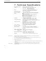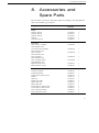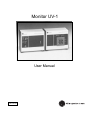
1
Monitor UV-1
User Manual
59-7797-01
Edition AG
Important user information
Reading this entire manual is
recommended for full
understanding and use of
this product.
●
The exclamation mark within an equilateral
triangle is intended to alert the user to the
presence of important operating and
maintenance instructions in the literature
accompanying the instrument.
Should You have any comments on this manual,
we will be pleased to receive them at:
GE Healthcare Bio-Sciences AB
S-75182 Uppsala
Sweden
Warranty and Liability
GE Healthcare Bio-Sciences AB guarantees that the
product delivered has been thoroughly tested to
ensure that it meets its published specifications.
The warranty included in the conditions of
delivery is valid only if the product has been
installed and used according to the instructions
supplied by GE Healthcare Bio-Sciences AB.
GE Healthcare Bio-Sciences AB shall in no event be liable
for incidental or consequential damages,
including without limitation, lost profits, loss of
income, loss of business opportunities, loss of
use and other related exposures, however
caused, arising from the faulty and incorrect use
of the product.
Trade marks
FPLC ® is the exclusive trade mark of
GE Healthcare Bio-Sciences AB.
In view of the risk of trade mark
degeneration, it is respectfully suggested that
authours wishing to use this designation refer to
its trade mark status at least once in each article.
Copyright © 1995 GE Healthcare
Bio-Sciences AB
GE Healthcare Bio-Sciences AB reserves the right to
make changes in the specifications without prior
All rights reserved. No part of this publication
notice.
may be reproduced, stored in a retrieval system
or transmitted in any form by any means,
without permission in written form from the
company.
Contents
1.
2.
3.
4.
5.
6.
7.
8.
Introduction ........................................................................................ 4
General Description .......................................................................... 5
2.1 Basic principle ............................................................................. 5
2.2 Optical unit ................................................................................. 7
2.3 Control unit ................................................................................. 9
Installation ........................................................................................ 11
3.1 Site requirements ...................................................................... 11
3.2 Unpacking ................................................................................. 11
3.3 Electrical connections .............................................................. 11
3.4 Installation of the filter ............................................................ 12
3.5 Installation of the flow cell ..................................................... 13
3.6 Connecting the optical unit .................................................... 14
3.7 Connecting a recorder ............................................................. 14
Operation .......................................................................................... 15
4.1 Choice of wavelength .............................................................. 15
4.2 Choice of AU or transmission (%T) ....................................... 15
4.3 Conversion table T% to AU and OD ..................................... 16
4.4 Start-up ...................................................................................... 16
4.5 Stabilization time...................................................................... 16
4.6 Basic operating procedure - AU ............................................. 17
4.7 Basic operating procedure - Transmission (%T) .................. 17
4.8 Shut down ................................................................................. 17
Maintenance ..................................................................................... 18
5.1 General precautions ................................................................. 18
5.2 Cleaning the flow cell .............................................................. 18
5.3 Changing the flow cell ............................................................ 19
5.4 Interference filters .................................................................... 20
5.5 Other optical surfaces .............................................................. 20
5.6 Instrument housing ................................................................. 20
5.7 Lamp and optical system test ................................................. 20
5.8 Changing the mercury lamp................................................... 21
5.9 Mercury lamp - maximum light adjustment ........................ 22
Trouble-shooting .............................................................................. 23
Technical Specifications .................................................................. 24
Accessories and Spare Parts ........................................................... 25
3
1. Introduction
1. Introduction
The UV-1 is a fixed wavelength UV monitor, consisting of a control
unit and an optical unit that can be positioned up to 10 meters apart.
A mercury lamp is the stable light source, furthermore a built-in
reference cell eliminates baseline drift. The output signal can be recorded in either AU or %T. Sensitivity range between 0.01 and 2 AUFS,
or (0-100%T).
The UV-1 offers a range of three detection wavelengths:
254, 280 and 405 nm. In addition, five flow cells are available for
different applications in Standard Chromatography, FPLC and
Industrial applications.
4
2. General Description
2. General Description
2.1 Basic principle
GE Healthcare LKB Monitor UV-1 consists of an optical unit
containing the flow cell, lamp, filter assemblies and preamplifiers, and a
control unit containing the signal processing circuits. The two units are
connected via a multi-core cable hardwired from the control unit to
the optical unit. Connection to the recorder and the mains supply is
made via the control unit.
The single path Monitor UV-1 is a dual beam instrument with a
sample cell and a reference cell. Optical path lengths are 10 mm,
3 mm, or 2 mm depending upon the flow cell chosen.
Note:
Flow cell S-2 has only the sample cell.
The sample cell and reference cell are angled to receive light from the
same point in the lamp (Fig. 1) thus assuring a stable base-line by
negating the effects of variations in lamp intensity.
The lamp is powered by a stabilized DC to AC converter operating at
20 kHz to maximize its efficiency. Lamp output is independent of
variations in the line voltage.
Light from the lamp passes through an aperture (254 nm, 405 nm) or
a fluorescence converter (280 nm) and through the reference cell and
sample cell. The light output from each cell passes through an
interference filter and falls onto a solid state photo-detector whose
output is a linear function of the light intensity (Fig. 1 and Fig. 2).
Fig. 1. Optical path.
5
2. General Description
Fig. 2 Block diagram
The photocurrent from each detector is amplified in a pre-amplifier
before passing to the signal processing circuitry in the control unit.
If transmission is to be monitored, the signal passes directly to the
low pass filter. If AU is to be monitored, the reference cell light
intensity (IR) is compared with the sample cell intensity (IS) to form
log (IR/IS) in a logarithmic circuit before passing to the low-pass filter.
The signal finally passes to the range selector before being presented
to the output terminal.
6
2. General Description
2.2 Optical unit
Front panel controls
5
4
1
2
3
Fig. 3. Optical unit. Front panel.
No.
Item
Description
1
Cell holder
The complete cell holder is removed by turning the
locking (Fig. 4:6) knob on the rear panel
2
Sample inlet
Inlet for sample flow
3
Sample outlet
Outlet for sample flow
4
Reference inlet
Inlet for flowing reference liquid. The reference cell
may be operated dry, with static reference liquid
5
Reference outlet
Outlet for flowing reference liquid
7
2. General Description
Rear panel controls
6
11
9
Guide pin
Screw
7
10
8
Fig. 4. Optical unit. Rear panel.
No. Item
Description
6
Locking knob
The cell holder is in locked position when the locking
knob is turned fully in the direction of the arrow
7
Filter inlet
8
Converter or
Filters, converters or apertures are inserted in the
positions indicated. When inserting them, align
the arrowhead on the end of the filter or converter
Aperturewith the arrowhead next to the appropriate
opening. Filters, converters and apertures must be
pressed fully
9
Support rod
Enables the optical unit to be mounted on laboratory
scaffolding. The rod may be secured in either of two
positions by a screw and a guide-pin
10
Support rod
Alternative position for support rod
11
Multi-core cable
Connects the optical unit to the control unit via
an 11-pin plug with a snap-lock. For disconnection
squeeze the ribbed sides of the plug firmly and pull
Warning:
8
The optical unit contains a UV-source which is exposed
if the cover is removed.
2. General Description
2.3 Control unit
Front panel controls
15
12
16
13
14
Fig. 5. Control unit. Front panel.
No.
Item
Description
12
Absorbance range
selector
Selector for the desired absorbance range
0.01, 0.02, 0.05, 0.1, 0.2, 0.5, 1 or 2 AU full scale
deflection. In the position SHORT, the signal output
terminals are disconnected from the rest of the control
circuitry and short-circuited. This position is useful when
setting zero on the recorder.
13
Mode switch
AU or %T
The AU / % T switch, enables the UV-1 to be used
to monitor the absorbance or transmission of a flowing
liquid. When the UV-1 is used in the AU mode, each of
the other position corresponds to the optical
absorbance which will give a full scale deflection (fsd)
on a recorder with a sensitivity of 10 mV. Absorbances
are measured relative to air or a liquid which is present
in the reference cell
When the recorder is used together with UV-1 in the
% T mode, the absorbance range selector switch is
used, together with baseline adjust, to adjust the
recorder response corresponding to 100 % T
14
Baseline adjust
Ten-turn potentiometer to adjust the recorder baseline
15
Indicator lamp
Indicates power is on
16
Mains switch
The UV-1 is turned on by switching this knob in the ON
(upper) position. The indicator lamp will light to show
that the mains voltage is on
9
2. General Description
Rear panel controls
Fig. 6. Control unit. Rear panel.
No.
Item
Description
17
Mains voltage selector
Selects mains voltage 110, 130, 220 and 240 V
18
Fuse holder
Mains fuses:
19
Signal outputs
The output signal is a 10 mV DC signal. The
terminals are connected to a potentiometric
recorder via shielded cables supplied. The
UV-1 is normally earthed via the mains ground
20
Mains inlet
Inlet for the mains cable
21
Optical unit inlet
Inlet for the optical unit
22
Ground terminal
To connect the shield of an output signal cable
Note:
10
1 x 250 mA for 110-130 V 60 Hz
1 x 125 mA for 220-240 V 50 Hz
Do not attempt to ground the control unit via the recorder
ground as the UV-1 is grounded via the mains ground.
3. Installation
3. Installation
3.1 Site
requirements
UV-1 should be installed on a stable, flat surface away from all sources of vibration. The atmosphere should be free of both excess humidity and corrosive or contaminated vapours which may form deposits
on the component in the optical path.
UV-1 can be installed either in a coldroom or at ambient temperature
in the laboratory. To minimise drift, the temperature should be kept
constant. UV-1 optical unit should be positioned away from all sources of draught, heat and direct sunlight. UV-1 should be placed away
from any compressor and the fan stream from coldboxes and coldrooms.
The UV-1 may be operated ambient temperatures in the range
0-40 °C (20-30 °C at full specifications).
One mains power point is required to operate UV-1. Separate power
points are required for all ancillary equipment, such as recorder.
The power consumption of the monitor is max 20 VA.
3.2 Unpacking
Note:
It is important that the interference filters and flow cells
should not be handled during unpacking. For protection of
these items they should remain in their packing materials
until required for use.
Carefully unpack the UV-1. Check the contents against the packing
list supplied. Inspect for any damage that may have occurred during
transit. Report any damage immediately to the local GE Healthcare
representative and to the transport company concerned. Save
the packing material if future transport can be foreseen.
3.3 Electrical
connections
The instrument is supplied with mains cables and fuses for both
100-130 V and 220-240 V operation.
1.
Ensure that the mains switch (Fig. 5:16) on the front panel of
the control unit is in the OFF position.
2.
Select the correct value of fuse from the fuse kits supplied.
For 110-130 V operation, use the 250 mA fuse supplied.
For 220-240 V operation, use the 125 mA fuse supplied.
Insert the fuse into the fuse cap, and then fit the fuse cap into the
fuse holder on the rear panel (Fig. 6:18) of the instrument.
3.
Check that the mains voltage selector (Fig. 6:17) on the rear
panel of the control unit is set to the mains voltage in the
laboratory. If necessary, turn with a thick bladed screwdriver the
mains voltage setting until appropriate setting is indicated in the
small window.
Note:
Use the 220 V setting for a 230 V mains outlet.
11
3. Installation
Mains voltage
Voltage selector setting
Fuse
110 V
130 V
220-230 V
240 V
110
130
220
240
250 mA
250 mA
125 mA
125 mA
4.
3.4 Installation
of the filter
Select the mains cable corresponding to your mains outlet.
Discard unwanted mains cable immediately. Connect the
instrument to a grounded mains outlet.
Note:
Do NOT switch on.
Note:
Special care must be taken when handling interference
filters. DO NOT touch the filter surface. The filters should
not allowed to come in contact with any liquid or exposed
to temperatures above 60 °C. For directions on cleaning
interference filters, see Section 5.4
1.
Select the appropriate filter for the wavelength to be used.
2.
Insert the filter and converter or aperture in the optical unit
(Fig. 4:7, Fig. 4:8). Each filter is marked with its wavelength and
the letter F. The 280 nm converter is marked 280 C. The
aperture for use with the 254 nm or 405 nm filters is marked 0.
The filter and converter or aperture must be pushed fully home.
12
Wavelength
Filter
Converter or Aperture
254 nm
280 nm
405 nm
254 F
280 F
405 F
0
280 C
0
3. Installation
3.5 Installation of
the flow cell
Monitor UV-1 accepts flow cells for Standard Chromatography, FPLC
and industrial applications.
Product
Code No.
Material of
wetted parts
Path
length
Total dead
volume
Illuminated Pressure
volume
limit
Application
area
S-2
19-4840-02
Fluoro-plastic,
optical quartz
2 mm
80 µl
2 µl
0.3 MPa
(3 bar)
Standard
Chromatography
HR-10
19-6254-02
Fluoro-plastic,
optical quartz,titanium
10 mm
24 µl
8.7 µl
1.0 Mpa
(10 bar)
FPLC, Standard
Chromatography
3 mm
19-2503-02
Fluoro-plastic,
optical quartz
3 mm
50 µl
3 µl
1.0 MPa
(10 bar)
Preparative FPLC,
Standard Chromatography
10 mm
19-2504-02
Fluoro-plastic,
optical quartz
10 mm
250 µl
8.7 µl
1.0 MPa
(10 bar)
Standard
Chromatography
5 mm
Industrial
Silicon rubber,
polypropylene,
5 mm
0.2 MPa*
(2 bar)
Industrial scale
19-4510-02
optical quartz
* Flow rate 300 I/h at 0.1 MPa
All flow cell are mounted in the holders, ready to be installed directly
into the cell housing. Release the locking knob (Fig. 4:6) by turning it
against the direction of the arrow and insert the flow cell in its holder
into the optical unit. Lock it in position by turning the locking knob
fully in the direction of the arrow.
For more information please refer to the instruction sheet supplied
with the respectively flow cell.
Fig. 9. 3 mm flow cell
Fig. 7. S-2 flow cell
Fig. 8. HR-10 flow cell
Fig. 10. 10 mm flow cell
Fig. 11. Industrial flow cell
13
3. Installation
3.6 Connecting
the optical unit
The optical unit may be placed on the bench or mounted on
laboratory scaffolding. For scaffolding mounting, mount the support
rod on the optical unit. The rod may be mounted horizontally or
vertically (Fig. 4:9). Tighten the the Allen screw firmly. The optical
unit should be placed as close as possible to the column outlet.
Connect the cable from the optical unit to the 1 l-pin socket on the
back of the control unit (Fig. 6:21). The plug has a snap lock.
To remove it, squeeze the ribbed sides firmly and pull.
3.7 Connecting a
recorder
There is one 10 mV signal output port on the rear panel of the
control unit. It is for use with GE Healthcare recorders or similar
instruments. Connect the output terminals to the input of the
recorder, using a signal cable (Fig. 12). Connect the shield of the
signal cable to the grounded terminal port on the rear panel of the
control unit. Choose the 10 mV input range on the recorder for full
scale response.
Fig. 12. Connections between the control unit and a dual channel recorder
Recorder REC 102.
14
4. Operation
4. Operation
4.1 Choice of
wavelength
The UV-1 can be operated at either 254 nm, 280 nm or 405 nm.
The choice of wavelength will depend on the spectral properties of
both the eluent and the substances to be detected. Proteins and polypep-tides containing aromatic amino acids are usually best detected at
280 and 254 nm. Nucleic acids and poly-nucleotides are usually best
detected at 254 nm and ferroproteins i.e. hemoglobins, cytochrome
and porphyrin derivatives at 405 nm.
4.2 Choice of AU or
transmission
(%T)
The UV-1 may be set to monitor either the absorbance or %
transmittance of a flowing liquid. Absorbance measurements give
recorder responses which are proportional to the solute concentration
when Lambert Beers Law is obeyed. The AU setting is thus most
appropriate for general use, particularly when quantitative results are
required. However, even with the 3 mm path length cell, there is
always a slight risk that the peak will go off scale. Under these
conditions, peak maxima can still be located by monitoring
transmission.
The relationship between AU and Optical density (OD) is
AU = L x OD
where L is the optical path length in cm.
The relationship between OD and transmission expressed as %T is
T%=
100
anti log10 (L . OD)
where L is the optical path length in cm.
15
4. Operation
4.3 Conversion
table T% to AU
and OD
4.4 Start-up
4.5 Stabilization
time
T%
AU
OD
(3 mm cell)
OD
(10 mm cell)
1
5
10
15
20
25
30
32
35
40
45
50
55
60
63
65
70
75
79
80
85
89
90
95
95.5
97.7
2.000
1.301
1.000
0.824
0.699
0.602
0.523
0.500
0.456
0.398
0.347
0.301
0.260
0.222
0.200
0.186
0.155
0.125
0.100
0.097
0.070
0.050
0.046
0.022
0.020
0.010
6.667
4.337
3.333
2.747
2.330
2.007
1.743
1.667
1.520
1.327
1.157
1.003
0.867
0.740
0.667
0.620
0.517
0.417
0.333
0.323
0.233
0.167
0.153
0.073
0.067
0.033
2.000
1.301
1.000
0.824
0.699
0.602
0.523
0.500
0.456
0.398
0.347
0.301
0.260
0.222
0.200
0.186
0.155
0.125
0.100
0.097
0.070
0.050
0.046
0.022
0.020
0.010
Note:
Always ensure that all liquid passing through the flow cell
are degassed to prevent any air bubble formation in the cell.
Liquids must be filtered to remove any particulate material
and prevent any blockage.
1.
Check that the monitor is correctly installed and that the sample
cell is filled with the appropriate eluent. The reference cell may
be left closed with air in the cell unless the UV-1 is used with
eluents showing appreciable UV-absorption. In this case the
reference cell should be filled with eluent.
2.
If the instrument has been switched off, turn on the mains switch
(Fig. 5:16) and refer to Section 4.5, to restabilize the instrument.
3.
Check that the appropriate filter and converter or aperture are in
place and fully inserted.
At normal laboratory temperatures the UV-1 requires 2 hours to
stabilize sufficiently. When the UV- 1 is in constant use, it is
recommended that it remains switched on. UV- 1 can be switched off
when not in use for periods of one week or more.
For coldroom operation below 10 °C, install UV-1 in the coldroom at
the desired running temperature at least 12 hours before the start of a
run. This is necessary to allow the instrument housing to equilibrate
to the temperature of the coldroom. Once equilibration has taken
place, the stabilisation times given for normal temperatures are valid.
16
4. Operation
4.6 Basic
operating
procedure AU
4.7 Basic
operating
procedure Transmission
(%T)
4.8 Shut down
1.
Switch AU/ %T to AU (Fig. 5:13).
2.
Set the range selector (Fig. 5:12) to SHORT and zero the
recorder with the recorder zero control.
3.
Set the range selector to 2 and adjust the recorder baseline with
the baseline adjust (Fig. 5:14).
4.
Set the range selector to the appropriate range and readjust the
recorder baseline with the baseline adjust (Fig. 5:14). Only
minor adjustment should be necessary.
1.
Switch AU to %T (Fig. 5:13).
2.
Set the range selector (Fig. 5:12) to SHORT and zero the
recorder.
3.
Turn the baseline adjust (Fig. 5:14) fully clockwise.
4.
Set the range selector so that the recorder gives a deflection just
greater than 100%.
5.
Adjust baseline to bring the pen back to 100%.
6.
Exchange the converter for the shutter and zero the recorder
with the recorder zero. This response will correspond to 0%
transmission.
7.
Replace the shutter with the converter. This response will
correspond to 100% transmission. Slight adjustment of baseline
may be required to obtain the response obtained in Step 5.
1.
On completion of the chromatographic run, flush the flow cell
either with pure solvent or the buffer used in the
chromatographic run. To prevent the deposition of salts from
aqueous buffers, flush the cell with distilled water after use, if
necessary after disconnecting the column.
Note:
2.
Never allow aqueous buffers to dry out in the cell. Either
continue to flush through with buffer or leave the cell filled
with distilled water.
Leave the UV-1 switched on. The monitor should only be
switched off if it is not going to be used again for more than one
week.
17
5. Maintenance
5. Maintenance
5.1 General
precautions
To ensure trouble free running, users are advised to observe the following precautions:
All liquids passing through the flow cell should be free of
suspended particles.
All liquids should be degassed to prevent air bubble formation in
the flow cell.
Never allow buffer solutions to dry out in the cell. Always rinse
the flow cell thoroughly with distilled water after use.
Handle interference filters with care. Never touch the optical
surfaces or expose them to temperatures above 60 °C.
5.2 Cleaning the
flow cell
For trouble free operation of the UV-1, it is essential that the flow cell
is free of any particulate matter and contaminant films. Ensure that
the flow cell is never allowed to dry out without having been thoroughly rinsed. Liquids containing dissolved salts, proteins or other
solutes will dry out, leaving contaminants on the inner optical surface
of the flow cell.
The cells may be inspected for particles by removing the cell holder
and examining the light paths with a magnifying glass.
If the cell contains trapped particles proceed as follows:
1.
Remove the cell holder from the optical unit.
2.
Connect a syringe to the outlet tubing and squirt a clean solution
of ethanol in distilled water (50% v/v) through the cell in small
aliquots. Examine the cell from time to time to see when the
particles have been washed out.
3.
Rinse the cell with particle-free distilled water (about 100 ml)
and replace it in the optical unit.
4.
Reconnect the cell holder to the system to be monitored.
Most non-particulate contaminants e.g. denaturated proteins, salts
etc. can be removed by flushing the cell with the appropriate solvent.
Finally, rinse the cell thoroughly with distilled water or clean solvent.
Oily deposits, which increase the tendency to trap bubbles, can be
removed by rinsing the flow cell first with a non-polar solvent
(e.g. hexane), then with a polar solvent (e.g. isopropanol) and finally
with distilled water or with detergent see procedure described on next
page.
18
5. Maintenance
Cleaning with detergent:
1.
Remove the cell holder from the optical unit.
2.
Pump undiluted cleaning detergent through the cell for at least
2 hours.
3.
Rinse the cell with
a) distilled water (100 ml)
b) ethanol/distilled water (50% v/v, 100 ml)
c) distilled water (100 ml)
4.
Replace the cell in the optical unit and reconnect the system to
be monitored.
Cleaning with chromic acid:
1.
Prepare fresh chromic acid by adding concentrated sulphuric
acid (100 ml) to a saturated solution of sodium dichromate
(3.5 ml).
Warning:
●
Chromic acid is extremly corrosive. Treat spills
immediately with a large excess of water.
2.
Remove the cell holder from the optical unit.
3.
Connect a glass syringe to the outlet side of the cell and carefully
draw chromic acid into the cell. Do not draw acid into the
syringe.
4.
Allow the acid to remain in the cell for 10-20 minutes. Longer
exposures (several hours) will not harm the cell.
5.
Eject the cleaning solution carefully without splashing and rinse
the cell with
a) distilled water (100 ml)
b) ethanol/distilled water (50% v/v, 100 ml)
c) distilled water (100 ml)
6.
5.3 Changing the
flow cell
Replace the cell in the optical unit and reconnect the system to
be monitored.
To change the flow cell, follow the instructions below.
1.
Switch the UV-1 off at the control unit.
2.
Disconnect the cell from the system being monitored and empty
it of liquid.
3.
Remove the cell holder from the optical unit.
4.
Remove the black cover by undoing the screw on top of the cell
holder. The tubing connections to the cell are now accessible.
Note their positions (Fig. 13).
5.
Loosen the connections using the tool provided. Do not undo.
6.
The cell may now be slipped out.
7.
Before inserting the new cell make sure the tubing ends do not
protrude into the cell compartment.
19
5. Maintenance
8.
9.
Insert the new cell, being careful not to touch either of the optical
surfaces. See that the inlet and outlet ports are correctly aligned.
Retighten the screw washers with the tool provided. Do not use
excessive force.
10. Check for leakage.
11. Replace the black cover.
Reference out
Sample out
Reference in
Sample in
Fig. 13. Flow cell interior showing tubing connections.
5.4 Interference
filters
For optimum performance, it is essential that the interference filters
are clean and free of any particulate material. Do not touch the interference filters. Should the filter become contaminated with dust,finger
prints or oil, proceed as follows:
- Carefully take out the filter without touching or scratching the
surface.
- Use lens cleaning tissue dipped in ethanol to gently clean both
sides of the filter surface.
- Place the clean filter back to the UV-1 or its box.
- Interference filters should never be exposed to temperatures
above 60 °C
5.5 Other optical
surfaces
Clean all other optical surfaces by wiping the surface with clean, lintfree cloth, moistened with carbon tetrachloride, ethanol, or another
suitable pure solvent.
5.6 Instrument
housing
Wipe the instrument regularly with a damp cloth. Let the instrument
dry completely before use.
5.7 Lamp and
optical system
test
Before performing this test see that the filter is clean, that the cell is
clean and free of bubbles or particles and that the cell holder is
correctly inserted and locked in position.
1. Insert the aperture and filter for 254 nm operation or the
converter and filter for 280 nm operation.
2. Set AU / %T to % T.
3. Set the recorder to the 100 mV range.
20
5. Maintenance
4.
Set the range selector to SHORT and zero the recorder.
5.
Set the range selector as follows:
254 nm, range 1
280 nm, range 0.2
6.
Turn Zero fully clockwise.
Response 8 mV or greater: the lamp is operating properly and the
optical system is clean.
Response 0 mV or very close to 0 mV: Contact a GE Healthcare
representative.
Response less than 8 mV but not very close to zero: check that the
cell and filter is clean. If fault persists, the filter or lamp may require
changing (see Section 5.7).
5.8 Changing the
mercury lamp
The low pressure mercury lamp has an expected lifetime of approx.
8000 hours. Before changing the lamp, carry out the tests described in
Section 5.6. If the tests indicates an aging lamp, proceed as follows.
l.
Disconnect the control unit from the mains supply and
disconnect the optical unit from the control unit.
Warning:
The control unit must be disconnected from the mains
and from the optical unit. If the UV-Iamp is broken
make sure that all mercury is removed.
2.
3.
Remove the cell holder.
Remove the two screws and locking washers which secure the
case of the optical unit to the bottom of the chassis.
4.
Loosen the two Philips screws until the top of the case can be
lifted clear of the catches.
5.
Pull the case forward, and remove it (Fig. 14).
Lamp Screw
Screw
Stop ring
Fig. 14. Optical unit interior with lamp driver circuit board removed
21
5. Maintenance
6. Use an Allen key (2.5 mm) to unscrew the upper of the two
screws securing the lamp holder and the lamp. Note carefully the
positions of the insulation sleeve and washer.
7. Disconnect the lamp from the PC-board.
8. Bend the upper part of the lamp holder slightly (2-3 mm)
upwards and withdraw the mercury lamp from it by gently
pulling the metal socket.
9. Insert the new mercury lamp and connect it to the PC-board.
10. Remount the upper lamp holder screw, ensuring that the
insulations are correctly mounted, reinstall the cell holder and
perform the maximum light adjustment described in Section 5.8.
5.9 Mercury lamp
- maximum
light
adjustment
Warning:
During this adjustment stray light may escape from the
UV source and protective glasses must be worn.
1. Connect the optical unit to the control unit and plug into the
mains supply.
2. Switch on the instrument and allow to warm up for about
10 minutes.
3. Insert a filter and the corresponding converter or aperture.
4. Connect the control unit to a recorder with a full scale response
of 50 mV.
5. Set the range selector to SHORT and zero the recorder.
6. Set AU/ %T to % T and turn the baseline adjust fully clockwise.
7. Select a range giving a pen deflection of approx. 50 % and then
rotate the lamp around its longitudinal axis until maximum pen
deflection occurs.
8. Set the range selector to SHORT and adjust the recorder zero to
bring the pen to the centre of the chart. Mark this pen position.
9. Set the range selector to 2 and set AU/ % T to AU.
10. Adjust the baseline control to its mid-position, five full turns
from either end of its range, by means of a tool, ie. an adjustable
spanner.
11. If necessary, adjust the lamp by turning it slightly to bring the
pen back to the position marked in step 8.
12. Reassemble the optical unit.
22
6. Trouble-shooting
6. Trouble-shooting
The UV-1 Monitor has been designed for trouble-free use. If good chromatographic practice is
followed, very little difficulty should be experienced. Clean optical surfaces are essential if low noise
levels are to be maintained. The following check list of the most frequent problems is meant to be a
guide in trouble-shooting. If the checks in this section are executed and the UV-1 still does not work
properly, consult your local GE Healthcare representative.
Symptom
Cause
Remedy
Pilot light does not light
1. Mains cord not plugged in
2. Fuse blown
Check that mains cord is plugged in
Replace fuse. If fuse blows again
immediately consult GE Healthcare representative
Check by plugging table lamp in
3. No voltage at mains socket
Pilot light on, no recorder 1. Optical unit not connected
to control unit
response
2. Control unit not connected
to recorder
3. Recorder not operating
4. Recorder zero not set correctly
5. Recorder range incorrect
6. Wrong filter
7. Filter not pushed in fully
8. Shutter in place
Excessive noise
1. Poor ground contact
2. Excess noise on mains supply
3. Recorder connections
incorrect
4. Recorder range incorrect
5. Dirty cell
6. Deposits on optical surfaces
7.
8.
8.
9.
Excessive baseline drift
Solvent with high UV absorption
Lamp not warmed up
Bubbles passing through the cell
Aging lamp
1. Variable absorbance gradient
2. Contaminated solvent
3. Large variation in ambient
temperature
4. Instrument warm-up
5. Condensation forming in
empty reference
Long term noise,
often regular waves in
recorder reponse
1. Variations in ambient temperature
especially in cold room
2. Flow rate variations
3. Poor ground contact
4. Bubbles passing cell
5. Dirty cell
6. Deposits on optical surfaces
Check that connecting cable is
plugged in
Check connection between output
terminals and recorder
Check recorder function
Zero recorder
Set recorder range to 10 mV
Check that the filter corresponds to
converter or aperture
Push in filter
Remove shutter and insert converter
or aperture as appropriate
Check contact to ground
Use alternative power source or
remove source of disturbance
Check connection between
output terminals and recorder
Set recorder on 10 mV range
Clean cell
Clean filter and converter
Relocate optical unit in a clean environment
Change to a more suitable solvent
2 h warm-up, in cold room 12 h
De-gas solvent. Check for leaks
Check lamp and replace if necessary
Compensate by use of reference cell
Use fresh solvent. Check that plastic tubing
does not leak UV absorbing substances
Relocate optical unit or remove
source of temperature change
Allow 2 hours warm-up
Flush reference cell with dry gas or
fill it with the appropriate solvent
Relocate optical unit or protect
from draught
Check pump system and column packing
Check contact to ground
De-gas solvent. Check for leaks
Clean cell
Clean filter and converter
Relocate optical unit in a clean environment
23
7. Technical Specifications
7. Technical Specifications
254 nm, 280 nm and 405 nm
Hg lamp: for 254, 280, and 405 nm
Life time lamp: 8000 hours
converter: 2000 hours
Interference. Stray light maximum 0,1 %
Filters
at 254 nm, maximum 0.8% at 280 nm
AU or Transmission
Operating modes
0.01, 0.02, 0.05, 0.1, 0.2, 0.5, 1 or 2 AUFS
Full scale ranges
4 x 10⁻⁵ AU peak to peak maximum at
Noise
254 nm (dry cell)
2 x 10⁻⁴ AU peak to peak (typical at
254 nm in flowing liquid)
5 x 10⁻⁴ AU peak to peak (typical at
280 nm flowing liquid)
At 254 nm, better than ± 3% to 2 AU
Linearity
At 280 nm, better than ± 5% to 1 AU
2 x 10⁻⁴ AU/°C typical with dry cell at
Temperature drift
254 nm <2 x 10⁻³ AU/°C typical with dry cell
at 280nm
1 x 10⁻⁴ AU/h at 254 nm, constant
Long term drift
temperature after 2 hours warm-up
4 x 10⁻⁴ AU/h at 280 nm, constant
temperature after 2 hours warm-up
1.5 s to 90% of FSD at all ranges
Time constant
0-10 mV
Recorder output
Environment
0 to +40 °C, 20-95 % relative humidity,
84-106 kPa (840-1060 mbar) atmospheric
pressure
20 VA
Power consumption
Power supply, voltage 100/120/220-230/240 Vfrequency
50-60 Hz
Dimensions (LxWxD) Control unit: 180x145x75 mm
Optical unit: 180x145x75 mm
Control unit: 1.6 kg Optical unit: 1.7 kg
Weight
Wavelength range
Lamp
EMC standards
This product meets the requirement of the EMC Directive 89/336/EEC through the harmonized standards
EN 50081-2 (emission) and EN 50082-1 (immunity)
Note: This is a class A product. In a domestic environment this product may cause radio interference in which
case the user may be required to take adequate actions.
Note: The declaration of conformity is valid for the instrument when it is:
●
●
●
Safety standards
24
used in laboratory locations
used in the same state as it was delivered from GE Healthcare Bio-Sciences AB except for alteration described in the
User Manual
used as “stand alone” unit or connected to other CE labelled GE Healthcare products or other products as
recommended.
This product meets the requirement of the Low Voltage Directive (LVD) 73/23/EEC through the harmonized
standard EN 61010-1.
8. Accessories and Spare Parts
8. Accessories and
Spare Parts
Please order accessories and spare parts according to the designation
and code numbers given below.
Designation
Code No.
Pieces
Filter kit, 254 nm
19-2432-01
1
Filter kit, 280 nm
19-2433-01
1
Filters
Filter kit, 405 nm
19-4724-01
1
Aperture
19-2492-01
1
Converter 280 nm
19-2486-01
1
19-4840-02
1
19-2504-02
1
19-2503-02
1
19-6254-02
1
19-4510-02
1
Measuring cell, 3 mm
19-2525-01
1
Measuring cell, 10 mm
19-2524-01
1
Flow cells
Flow cell S-2 complete
with measuring cell
Flow cell 10 mm complete
with measuring cell
Flow cell 3 mm
with measuring cell
Flow cell HR-10
with measuring cell
Flow cell large volume
with measuring cell
Accessories and Spare parts
UV lamp complete
19-3807-01
1
Tubing and fittings
19-2505-01
1
Tubing, PTFE, (pack of 5 m)
19-0041-01
1
Shutter
19-2491-01
1
Allen key
19-0379-01
1
Signal input cable
19-2853-01
1
Mains cable, US
19-2447-01
1
Mains cable, EU
19-2448-01
1
Fuse holder for 125 mA fuse
19-2925-01
1
Fuse holder for 250 mA fuse
19-2926-01
1
Fuse, 125 mA for 220 V
19-2367-01
5
Fuse, 250 mA for 110 V
19-2368-01
5
25
Printed in Sweden by SNITS & DESIGN AB/Västra Aros Tryckeri, Nov 1996