1
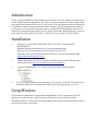
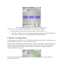
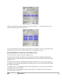
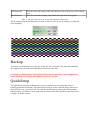
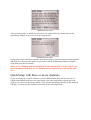
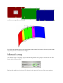
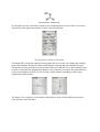
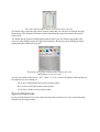
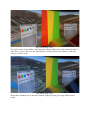
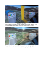
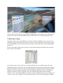
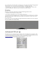
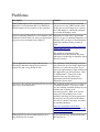
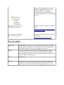
User manual version 3.0
Author: Robert Malmstrom and Ivar Hestnes
Index
Introduction.................................................................................................................................3
Installation...................................................................................................................................3
SetupWindow..............................................................................................................................3
Channel configuration.......................................................................................................4
SetupWindow buttons and functions.................................................................................5
Backup........................................................................................................................................6
QuickSetup..................................................................................................................................6
QuickSetup with three or more channels...........................................................................7
Manual setup...............................................................................................................................8
Special functions..............................................................................................................10
Warping............................................................................................................................11
Edge blend.......................................................................................................................12
Blend graph......................................................................................................................13
Uniform colors.................................................................................................................16
Masking...........................................................................................................................17
Advanced 3D set up..................................................................................................................17
Keyboard commands.................................................................................................................18
WarpalizerConfig.XML parameters..........................................................................................18
Problems....................................................................................................................................20
Word table.................................................................................................................................21
Introduction
This is a manual on how to setup a multi projector system on a flat, single- or double curved
screen with the software Warpalizer. The easiest way to get started is to read the QuickSetup
description in this manual and test it on your system. The QuickSetup function in Warpalizer
will produce a quick and good estimation of the warping, edge blend and overlap setup for
your system. To get a perfect setup you need to read about the SetupWindow and how you
control the warping and edge blend reference points. Remember that QuickSetup is always a
good start of a setup so that you just have to fine tune to get a perfect seamless image.
Installation
1.
Warpalizer is built with Visual Studio 2010 so you have to download the
Redistributable
Runtime Package from Microsoft. It can be downloaded from:
http://www.microsoft.com/download/en/details.aspx?id=5555
And make sure you have the latest DirectX drivers. It can be downloaded from
support.microsoft.com/kb/179113
2.
Unpack Warpalizer.rar (This can be done with the software WinRAR that can be
downloaded from: http://www.win-rar.com/download.html)
3.
Copy the unpacked files to C: so that you get the following file structure:
4:
To use your application with the warpalizer, just copy the “d3d9.dll” file found in the
warpalizer folder into the applications folder, where the applications .exe file is.
SetupWindow
You control the Warpalizer set up from the SetupWindow and it is opened on top of the
application so that you can see the warping result directly and fine tune in runtime.
The Setup window is always opened in the middle of the left most channel/projection screen
and the layout can be seen below.
The SetupWindow from where you control the warping set up.
There are two ways to open the SetupWindow in the warpalizer software.
1. Run DirectXtest.exe from the warpalizer folder and press Shift + F2
2. Click Shift + F2 when you are running the application that has the d3d9.dll, d3d10.dll
or the d3d11.dll pasted or if you are running the DesktopWarpalizer.
Channel configuration
The first thing you should do is to set the number of channels/projectors you are using in your
system and the way they are set up in columns and rows.
In the top of the SetupWindow you find the text “Columns” and “Rows” and beside them you
find the number of columns and rows currently set in the system. You use the up and down
arrows, to the right of the column number and the row number, to change the number of
columns and rows of projectors.
If you press the up button beside “Columns: 3” then you will get a 4x1 system with four
projectors on one row.
And if you instead press the up button next to the text “Rows:
system with three projectors in two rows.
1” then you will get a 3x2
If you press the down arrows then you will remove one column or one row of projectors. Do
not forget to press the “Save” button so that your new settings are saved.
SetupWindow buttons and functions
The Reset button is used to reset the warping set up.
The button Edit in the lower right corner starts the edit mode for manually setting up the
warping and edge blend and edge blend graph. Read more about edit mode under the subtitle
Manual setup
The button Calib starts the QuickSetup functionality that helps you to do a quick and good
estimation of the warping, edge blend and overlap setup. You can read more about this under
the subtitle QuickSetup.
The button Load is for loading the latest saved warping setup. A description of the files that
are loaded can be seen in Table 1.
The button Save is for saving the current warping setup. A description of the files that are
saved can be seen in Table 1.
File
Description
Data/Setup.dta
This file stores the setting of the SetupWindow with overlap size, color settings
a.s.o.
Data/Warp.dta
This files stores the warping, edge blend and edge blend color graph.
Table 1. The files that stores the setup information in Warpalizer.
The Test image buttons and functions are used to make it easier to set up warping, overlap and
color matching.
Test image used when controlling overlap and warping for a 2D setup.
Backup
To backup a configuration, just copy the “setup.dta” and “warp.dta” files from the datafolder.
We suggest that you make a backupfolder to keep these files safe.
It is highly recommended to backup these files between each step of your configuration
work, and before you update the software to a newer version.
QuickSetup
The QuickSetup function in Warpalizer is an easy and fast way to perform the setup of
warping (geometric distortion), edge blend and overlap to create a unified image with two or
three projectors on a curved screen. You start the QuickSetup by opening the Setup window
and press the Calib button. On the start menu you must select if the physical projection screen
is single- or double curved.
QuickSetup start menu.
After selecting singe- or double curved screen you simply follow the instructions in the
QuickSetup window as you can see in the image below.
QuickSetup instructions.
If you want to move the latest reference point that you have clicked just press the Back button
and click the reference point again. If you want to exit the QuickSetup without saving the
setup then press the Exit button.
When you are finished with the QuickSetup it will automatically save the setup. If you
press the button Exit before you are finished with the QuickSetup it will skip the auto
save.
QuickSetup with three or more channels
If you are setting up a system with three or more channels then there will be one more so
called center channel that have two edge blends. One edge blend to the left and one to the
right as you can see on the images below. If you run the QuickSetup then the center channels
will have 10 control points instead of 8 because of the extra edge blend.
The center channel in a three channel system.
Just follow the instructions in the QuickSetup window and click on the reference points in the
way that you can see in the above images.
Manual setup
The manual setup of warping, edge blend and edge blend color graph is started with the Edit
button in the Setup window.
During edit mode there is the text Edit shown in the upper left corner of the mouse pointer.
Mouse pointer in edit mode.
In edit mode you move the mouse pointer to the channel/projector screen where you want to
edit and press the right mouse button to open a drop down menu.
The drop down window in edit mode.
The button Warp opens the warping control points that you can move to change the warping
setup of the channel. Read more about controlling the warping under the subtitle Warping.
The button Overlap opens the Overlap window where you edit this size of the horizontal- and
vertical overlap between neighboring channels. You control the overlap to the right and above
of the current channel so there are two versions of this window depending on how many
neighboring channels there.
The two versions of the Overlap window.
The button Color opens the Color match window that is used to match different projectors
color intensity with each other.
The color match window used to color match the projectors.
The button Edge opens the edge blend control points that you can move to change the edge
blend setup of the channel. Read more about controlling the edge blend under the subtitle
Edge blend.
The button Blend opens the blend graph window where you can edit the edge blend color
setup of a edge blend to make the edge blend seamless. Read more about editing the blend
graph under the subtitle Blend graph.
The Blend color graph window used to control the color
and brightness of the overlap.
You can set a mark in the box for “All”, “Row” or “Col” to move all marked control points on
the channel you are working on..
All to move all horizontal and vertical control points.
Row to move all the horizontal control points.
Col to move all the vertical control points.
Special functions
If you press the button Func in the edit mode drop down window you will see the following
functions in the image bellow.
Special function state of the edit mode drop down window.
The vertical slide bar under the label Scale is used to scale the chosen warp matrix. This
function is very useful if you have changed the lens zoom of a projector and want the warp
matrix to be re-sized back to the original size without changing your previous settings.
The buttons Double and Half under the label Control points is used to double or half the
number of control points in all warp matrices. Be aware that if you half the number of control
points then you will lose the positions of every other control points. So if you change back to
the double amount of control points you will have lost some position accuracy. If you have
changed the number of control points and want to undo the change just press the Exit button
and open the Setup Window and press the Load button.
When you are finished with the func mode of the drop down window you press the Back
button to move back to the standard drop down window or press Exit to exit the edit mode.
Warping
Warping is when you geometrically distorts an image and in Warpalizer this can be done in
edit mode. How you enter edit mode and how you select which channel you wont to edit the
warping can be read under the subtitle Manual Setup. Before you enter edit mode there is a
good idea to open the test image by pressing the check box to the right of the text Test image
in the SetupWindow.
The image below shows an example of how it looks when you enter edit mode and selects
Warp. Here you can see the 5 * 5 warping control points where the upper left control point is
pointed out by the white arrow.
2D Warp edit mode with the test image turned on.
The warping control points for a channel are green when you are in edit mode and have
selected Warp in that channel. The warping control points in the other unselected channels are
red.
If you move the mouse pointer to the upper left control point and then press left mouse button
you can move the control point until you release the button.
If you select a control point it changes from a green to a blue circle as you can see on the
image below. When a control point is selected it can be moved with the mouse and with the
arrow keys on the keyboard for high precision moving.
A selected control point.
Do not forget to open the SetupWindow after editing and press the button Save to save the
changed setup. It is not fun to lose hours of work if your computer fail or something goes
wrong.
Edge blend
Edge blending is when one or more edges on an image has a gradient towards black. This
gradient is used to blend two or more images in to one seamless image. The image bellow
shows an example of how it looks when you enter edit mode and selects Edge blend. Here
you can see the 2 * 5 edge blend control points where the center left control point is the active
point.
Edge blend edit mode with the test image turned on. Left channel active.
If you move the mouse pointer to the upper left control point and then press left mouse button
you can move the control point until you release the button, or use the keyboard arrows in the
same way as described earlier for the warping.
In the blend area for each channel, it is three columns of control points. At the beginning, it is
highly recommended to use the “column” feature when moving the points to get familiar with
this.
In the image above, you can see the two rows that define the area of blending. This is the area
that will appear “bright” on your screen.
The third row (not seen in the image above) is the curtain which defines the gamma. This will
normally be on top of a blend zone row of control points.
Blend graph
The Blend color graph window is used to edit the edge blend color gradient. When you open
the blend color graph window you can change the overall brightness and the selected edge
blend by moving the white control points. If you want to change just the red color in some
part of the edge blend you must first press the red point in the upper left corner of the window
and you can then move the red control points. The red control points in image bellow are
hidden under the blue control points. You select the green or blue control points by pressing
the green or blue point in the upper left corner of the window. If you press the point that is
half white and half black you can then move the white control points.
The red, green and blue boxes on the top-right are for highlighting the entire blending area.
When you start to edit an edge blend between to projectors then you should start by making
the left projectors right edge blend red and the right projectors left edge blend green.
Edge blend setup step 1.
The yellow stripe in the middle of the edge blend shows where the overlap starts and where it
ends. Now you can start move the left projectors red edge blend control points so that you
only get a yellow stripe.
Edge blend setup step 2.
When this is finished you do the same with the right projectors green edge blend control
points.
Edge blend setup step 3.
Now you can turn of the red and green edge blend and start fine tune the “hardness” of the
edge blend with the slide bar. Usually you now have a bright stripe in the overlap.
Edge blend setup step 4.
When you adjust the hardness you should change both the left and the right edge blend
hardness to the same slider position/value to get the best quality of the edge blend.
Edge blend finished.
You can now also fine tune the edge blend by dragging the control points in the “Blend color
graph” but we only recommend doing this if you have done a lot of edge blend practicing.
Uniform colors
The three colors (red, green and blue) can only be reduced in brightness so to set up a color
uniformed image with several projectors you have to use the strategy to let the projector with
the least brightness be the reference projector and then reduce the colors of the other brighter
projectors.
In the Color match window there are three vertical slide bars that control the red, green and
blue color of each channel.
Set a mark in the connect sliders box to adjust all sliders for one channel at the same time.
Under the label Test image there are two triangle buttons for opening six different test images.
Mark the checkbox to activate, and select the appropriate image by using the triangle buttons.
Number one to four opens test images used for setting up uniformed colors. The color test
images are white, red, blue, and green. You can read more about this under the subtitle
Uniform colors. Test-image number five and six can be selected by the user. For example, you
can use a screen shot “in-game” of the application that you will run with Warpalizer. (Make
sure you take the screen shot with no warping in use). To replace the default “Testing pattern”
and the “globe-view”, just rename your screenshots to “Testimage1.jpg” and
“Testimage2.jpg”. Paste them into the following folder C:\Warpalizer\Data\Textures, and
replace the default ones. Make sure your screen shots is in JPEG format.
Masking
Masking of areas can be achieved by setting the following parameter in the
C:\Warpalizer\Data\WarpalizerConfig.xml file:
<USE_MASK_TEXTURE>true</USE_MASK_TEXTURE>
You can then open the following picture C:\Warpalizer\Data\Textures\Mask.tga in a painting
application (for example GIMP) and edit the image with a black pen to mask of any area of
the warped image.
Down bellow you can see the Mask.tga image that from the start mask of for some cockpit in
the lower middle of the warping image.
The masking texture Mask.tga
Advanced 3D set up
The button Adv is for “advanced setup”, and this is the 3D configuration of warpalizer. This
will project horizontal and vertical degrees based on your physical screen dimensions. Please
read our 3D setup tutorial to learn how to use this advanced feature. Mail
[email protected] and ask for the 3D setup tutorial.
Keyboard commands
Key
Function
Shift + F1
Set show warping on/off.
Shift + F2
Open SetupWindow.
Shift + F3
Double the number of control points.
Shift + F4
Half the number of control points.
1,2,3..
If you are in edit warp control points mode then you can change which
screen/projector to edit by pressing a number.
If you are in edit edge blend control points mode then you can change which
edge blend to edit by pressing a number.
A
Move all control points on the selected warp- or edge blend matrix.
C
Move column of control points on the selected warp- or edge blend matrix.
R
Move row of control points on the selected warp- or edge blend matrix.
Arrow
If you are in edit warp- or edge blend control points mode then you can move
the selected control point in small steps by pressing the arrow keys.
keys
M
If you are in edit warp- or edge blend control points mode then you can press M
once and then change the control point to edit by pressing the arrow keys. You
then press M again to move back to moving the control points with the arrow
keys.
B
If you are in edit warp- or edge blend control points mode then you can press B
once then you will move the control point in bigger steps. If you then press B
once more then you move them in small steps again.
WarpalizerConfig.XML parameters
To change the configuration of Warpalizer you must change the parameters in the file
C:\Warpalizer\Data\WarpalizerConfig.xml. Here is a description of each parameter.
<PARAMETERS>
<WARPALIZER>
<CLIENT>false</CLIENT>
<OVERLAP_FACTOR>0.85f</OVERLAP_FACTOR>
<2OVERLAP_FACTOR>1.0f</2OVERLAP_FACTOR>
<MULTI_SCREEN_OVERLAP>0.05</MULTI_SCREEN_OVERLAP>
<AUTO_LOAD_WARPING>true</AUTO_LOAD_WARPING>
<SHOW_WARPING_FROM_START>true</SHOW_WARPING_FROM_START>
Set to true to make the warping be shown from start of application without the need to press
“Shift + F1”.
<EDGE_BLEND_TEXTURE>false</EDGE_BLEND_TEXTURE>
<USE_MASK_TEXTURE>false</USE_MASK_TEXTURE>
<REMOVE_FRAME>false</REMOVE_FRAME>
Set to true for removing window borders in FSX, FS9, ESP and
Prepar3D
<FRAME_THICKNESS>2</FRAME_THICKNESS>
Number of pixels to remove for window border in FSX, FS9, ESP
and Prepar3D
<GUI_WINDOWS_SIZE>1.0f</GUI_WINDOWS_SIZE>
<USE_GET_CURSOR_POS>false</USE_GET_CURSOR_POS>
Set to true to connect warping cursor with windows cursor.
This is necessary for remote support via teamviewer.
<SHOW_LURE_MUS>false</SHOW_LURE_MUS>
<SHOW_VIEW_SETUP_CYLINDER>true</SHOW_VIEW_SETUP_CYLINDER>
<CYLINDER_HORIZONTAL_FOV>270.0f</CYLINDER_HORIZONTAL_FOV>
<CYLINDER_VERTICAL_FOV>60.0f</CYLINDER_VERTICAL_FOV>
</WARPALIZER>
</PARAMETERS>
Problems
Description
Solution
If the USB dongle do not stop flashing a green
light after 10 seconds then that is an indication
that the dongle can not connect to the computer.
Try to reconnect the dongle and make
sure not to use any USB extender cable.
If this does not work then try to connect
the USB dongle to a different computer
to see that the dongle works.
If you try running Warpalizer on a computer with Warpalizer is built with Visual Studio
Windows XP and when you start your application 2010 so if you are running Warpalizer on
you get an error message from windows.
Windows XP you have to download and
install the runtime library to make it
work:
http://www.microsoft.com/download/en/
details.aspx?id=5555
The problem could also be that
Warpalizer uses the DirectX API from
Microsft for rendering so install the latest
DirectX version.
If your application do not start when you try
Warpalizer and there has not been created a
Log.txt file and a Log_D3D9.txt file.
The problem is that Warpalizer has not
got permission to write in the application
directory to create the log files. Try to
start your application by right clicking on
the application exe-file and select “Run
as administrator”. Then look in the
bottom of the two log files to get
information about the problem why
Warpalizer do not start.
If you have the problem that DirectXTest.exe only The problem is that you have to setup an
runs on one screen/projector.
"Extended desktop". You can see that
you are running extended desktop if your
window bar is shown in all
screens/projectors. With your current
setup you will probably just see the
windows bar in the left screen/projector.
If you have an ATI card with Eyefinity
you can see in this video how you setup
an extended desktop:
http://www.youtube.com/watch?
v=aYorUpN4PQo&playnext=1&list=PL
0BD355C364FFAB2A
If DirectXTest.exe do not start but there are a
Log_D3D9.txt file created.
If you open the Log_D3D9.txt file and
the first line is:
Logger::LoadLoggingSetup, Couldn´t
find the LoggingSetup.ini file in the
working directory = No logging.
Then the problem is that you have to
have the Warpalizer files in the following
location:
If you get the error message:
MSVCR100.dll missing
Install the runtime for MS visual studio
2010:
http://www.microsoft.com/download/en/
details.aspx?id=5555
If you get the error message:
d3dx9_42.dll is missing
Install the latest DirectX drivers that can
be found at:
support.microsoft.com/kb/179113
Word table
Edge blend
Edge blending is when one or more edges on an image has a gradient
towards black. This gradient is used to blend two or more images in to
one seamless image. See also the description of Overlap.
Overlap
A overlap is the region on the edge of a channels/projectors image
where the image has the same content as the neighboring channels
image so that the two images can be edge blended in the overlap region
to make a single seamless image.
FOV
Field of view.
Warping
Warping is when you geometrically distorts an image. In Warpalizer
warping is used to geometrically distorts the image so that it can be
projected on a curved screen without looking distorted to the viewer.