1
HDS7000
User Manual
Version 1.1
English
2
HDS7000, Introduction
Introduction
Purchase
Congratulations on the purchase of a HDS7000 instrument.
This manual contains important safety directions as well as instructions for setting
up the product and operating it. Refer to "6 Safety Directions" for further information.
Read carefully through the User Manual before you switch on the product.
Product
identification
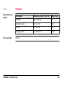
The type and the serial number of your product are indicated on the type plate.
Enter the model and serial number in your manual and always refer to this information when you need to contact your agency or Leica Geosystems authorised service
workshop.
Type:
_______________
Serial No.:
_______________
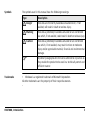
Symbols
The symbols used in this manual have the following meanings:
Type
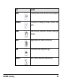
Danger
Warning
Caution
)
Trademarks
Description
Indicates an imminently hazardous situation which, if not
avoided, will result in death or serious injury.
Indicates a potentially hazardous situation or an unintended
use which, if not avoided, could result in death or serious injury.
Indicates a potentially hazardous situation or an unintended
use which, if not avoided, may result in minor or moderate
injury and/or appreciable material, financial and environmental
damage.
Important paragraphs which must be adhered to in practice as
they enable the product to be used in a technically correct and
efficient manner.
• Windows is a registered trademark of Microsoft Corporation
All other trademarks are the property of their respective owners.
HDS7000, Introduction
3
4
HDS7000, Table of Contents
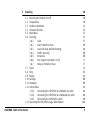
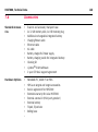
Table of Contents
In this manual
Chapter
1
Description of the System
1.1
1.2
1.3
1.4
1.5
1.6
2
Page
Packing / Unpacking
Container Contents
Instrument Components
Cabling
1.4.1
Operate the HDS7000 with the Battery
1.4.2
Operate the HDS7000 with the Battery Charger
(AC Power Supply)
1.4.3
USB Ports
Field of View (FOV)
HDS Cyclone Software Suite
8
8
9
11
16
16
22
24
26
27
Setting Up the Instrument
30
2.1
2.2
2.3
2.4
2.5
30
31
33
36
37
General Information
Scanner Setup on Tripod
Setup Over a Benchmark with the Internal Laser Plummet
Instrument Height
Setting Up the Instrument with the Dolly
3
Scanning
3.1
3.2
3.3
3.4
3.5
3.6
3.7
3.8
3.9
3.10
3.11
3.12
3.13
HDS7000, Table of Contents
Switching the System On/Off
Preparations
Ambient Conditions
Onboard Controls
Main Menu
Scanning
3.6.1
Level
3.6.2
Start Predefined Scan
3.6.3
Scan with User Defined Settings
3.6.4
Profile Scanning
3.6.5
Panorama
3.6.6
One Target Orientation (1-TO)
3.6.7
Setup a Predefined Scan
Scans
Help
Status
Settings
Hardware
Connections
3.12.1
Connecting the HDS7000 to a Network by Cable
3.12.2
Connecting the HDS7000 to a Notebook by Cable
3.12.3
Connecting the HDS7000 by Wi-Fi
Operating the HDS7000 using a Web Browser
38
38
39
42
45
51
53
57
59
60
68
69
71
73
74
83
84
86
89
92
94
96
99
100
5
6
HDS7000, Table of Contents
4
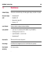
Troubleshooting
104
5
Care and Transport
108
5.1
5.2
5.3
5.4
5.5
5.6
5.7
108
109
110
111
112
114
115
6
Check & Adjust
Transport
Storage
Cleaning and Drying
Window Cleaning Procedure
Adjustment of the Circular Level
Service of the Tripod
Safety Directions
116
6.1
6.2
6.3
6.4
6.5
6.6
6.7
6.8
116
117
119
120
121
130
132
135
General Description
Intended Use
Limits of Use
Responsibilities
Hazards of Use
Laser Classification Scanner, Invisible Laser
Electromagnetic Compatibility EMC
FCC Statement, Applicable in U.S.
7
Technical Data
140
7.1
7.2
7.3
140
141
144
145
146
147
148
150
151
7.4
7.5
7.6
7.7
7.8
8
General Technical Data of the Instrument
Laser Scanning System
Miscellaneous
7.3.1
Electrical
Environmental
Physical
Accessories
Wi-Fi
Conformity to National Regulations
International Limited Warranty, Software Licence Agreement
Index
HDS7000, Table of Contents
152
154
7
8
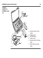
HDS7000, Description of the System
1
Description of the System
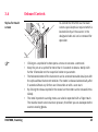
1.1
Packing / Unpacking
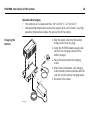
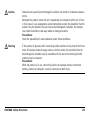
Unpacking
When in its transport container, the HDS7000 sits in with the Wi-Fi antenna in faceup position.
To take the instrument out of its container,
grasp the handle and the base of the instrument, and lift.
Use caution due to the weight of the instrument (9.8 kg).
HDS7000_001
)
Pack the instrument the same way it is delivered.
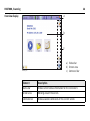
1.2
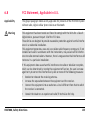
Container Contents
Transport
container for
HDS7000
a
b
c
d
HDS7000_002
HDS7000, Description of the System
a)
b)
c)
d)
USB plug
User Manual
HDS7000
Glass cleaning kit
9
10
HDS7000, Description of the System
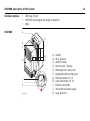
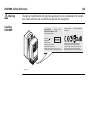
Transport
container for
HDS7000 accessories
a
b
d
e
f
HDS7000_003
c
a) AC power supply / battery
charger
b) Charging cradle
c) HDS7000 battery
d) Ethernet cable
e) Extension cable for AC power
supply
f) Power cable for AC power
supply
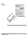
1.3
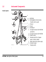
Instrument Components
Overall system
h
HD
S7
000
i
j
a
b
c
d
e
k
l
f
g
HDS7000_004
HDS7000, Description of the System
a) HDS7000
b) Rechargeable internal battery
("battery" will be used)
c) Tribrach
d) Tripod
e) Cleaning kit
f) Transport container for HDS7000
accessories
g) Transport container for HDS7000
h) Ethernet cable
i) Extension cable for AC power
supply / battery charger
j) Power cable for AC power supply
k) AC power supply
l) Charging cradle
11
12
HDS7000, Description of the System
Hardware options
•
•
•
HDS7000
a
USB plug (32 GB)
HDS7000 scan targets and target accessories
Dolly
e
b
c
f
d
i
j
k
HDS7000_005
0
00
S7
HD
g
h
a)
b)
c)
d)
e)
f)
g)
h)
i)
j)
k)
Handle
Wi-Fi antenna
ON/OFF button
Touch screen / Display
Rotating mirror (Laser exit)
Designated slot for stylus-pen
USB Connectors, P1, P2
Lemo Connectors, P3, P4
Ethernet connector
Connector for power supply
Laser plummet
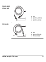
Battery and
charging cradle
a
b
ER
HDS7000_006
)
g
R
f e
d
c
a)
b)
c)
d)
e)
Battery
Charging cradle
Battery status indicators
Connector for power supply
Green LED: Power indicator
LED
f) Red LED: Error LED
g) SupD-9 plug: connects
battery and charging cradle
Use the SupD-9 plug only for connecting to the battery.
HDS7000, Description of the System
13
14
HDS7000, Description of the System
AC power supply /
Battery charger
a
b
c
HDS7000_007
a) Power cable for AC power
supply
b) AC power supply
c) Lemo plug (3 pin, female)
Extension cable for
AC power supply
a
b
c
Ethernet cable
a) Cable
b) Connector 3 pin, female
c) Connector 3 pin, male
a
GEV228
HDS7000, Description of the System
b
c
a) Cable
b) Connector, 8 pin male
c) Ethernet connector
15
16
HDS7000, Description of the System
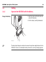
1.4
Cabling
1.4.1
Operate the HDS7000 with the Battery
1. Hold the battery with both hands and
press the fixing clips.
2. Pull the battery carefully downwards.
Change the battery
HD
S7
000
1
2
1
HDS7000_008
)
A battery should always be attached to ensure the optimum weight balance for the
HDS7000. If there is no removable battery connected, a warning message appears.
)
)
)
Never remove the battery while the HDS7000 is switched on.
Precautions:
• Switch off the HDS7000 beforehand or
• use the external power supply
If the HDS7000 is operated until the battery is completely empty, it has to be
recharged immediately. Failure to do this can result in battery damage.
Primary use/charging
• The batteries must be charged prior to using for the first time because it is delivered with an energy content as low as possible.
• For new batteries or batteries that have been stored for a long time (> three
months), it is effectual to make only one charge/discharge cycle.
• For Li-Ion batteries, a single discharging and charging cycle is sufficient. We
recommend carrying out the process when the battery capacity indicated on the
charger or on a Leica Geosystems product deviates significantly from the actual
battery capacity available.
• The permissible temperature range for charging is between 0°C to 40°C / +32°F
to +104°F. For optimal charging we recommend charging the batteries at a low
ambient temperature of +10°C to +20°C / +50°F to +68°F if possible.
• It is normal for the battery to become warm during charging. Using the chargers
recommended by Leica Geosystems, it is not possible to charge the battery if the
temperature is too high.
HDS7000, Description of the System
17
18
HDS7000, Description of the System
Operation/Discharging
• The batteries can be operated from -20°C to +55°C / -4°F to +131°F.
• Low operating temperatures reduce the capacity that can be drawn; very high
operating temperatures reduce the service life of the battery.
Charging the
battery
1
3
R
ER
HDS7000_009
2
1
1. Plug the power cable into the battery
charger and into an AC plug.
2. Using the HDS7000 power supply cable
connect the charging cradle and the
battery charger.
3. Place the battery onto the charging
cradle.
4. After 30sec initialization, the charging
cradle’s battery status indicators will indicate the current battery charging status.
5. Disconnect the cables.
)
Charging of the battery takes approximately 1.5 hours.
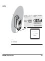
Understand the charging cradle’s LEDs:
a
ER
R
HDS7000_010
HDS7000, Description of the System
b
c
a) Battery status indicators
b) Power indicator LED (green)
c) Error LED (red)
19
20
HDS7000, Description of the System
Battery status
indicators
•
•
If all four LEDs flash continuously then there is no battery in
the charging cradle.
The overall charging capacity of the battery is divided into
quarters. Each LED corresponds to a quarter:
• If the battery charge state is low the appropriate LED
flashes slowly.
• The LED flashes faster as the charge state improves.
• If an LED illuminates constantly the battery has reached
the appropriate level of charge.
• When all four LEDs illuminate constantly the battery is
100% charged.
Error LED
The red LED illuminates if there is a fault in the electricity supply.
Please refer to "HDS7000 Battery" in "4 Troubleshooting".
Power indicator
LED
The green power indicator LED illuminates if the charging cradle
is under voltage.
Danger
Danger
Warning
For AC power supply:
The product is not designed for use under wet and severe conditions. If unit becomes
wet it may cause you to receive an electric shock.
Precautions:
Use the product only in dry environments, for example in buildings or vehicles.
Protect the product against humidity. If the product becomes humid, it must not be
used!
Death or serious injury can occur if unit is not connected to ground.
Precautions:
To avoid electric shock power cable and power outlet must be grounded.
Batteries not recommended by Leica Geosystems may be damaged if charged or
discharged. They may burn and explode.
Precautions:
Only charge and discharge batteries recommended by Leica Geosystems.
HDS7000, Description of the System
21
22
HDS7000, Description of the System
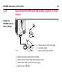
1.4.2
Operate the HDS7000 with the Battery Charger (AC Power
Supply)
Operate the
HDS7000 with the
battery charger
HDS7000
3
a
1
2
b
HDS7000_011
1.
2.
3.
4.
c
a) Power cable for AC power supply
b) AC power supply
c) Power cable to the HDS7000
Connect the power cable to the HDS7000.
Connect the AC power supply with the power cable.
Connect the power cable to the main supply.
Switch on the HDS7000.
Danger
Danger
For AC power supply:
The product is not designed for use under wet and severe conditions. If unit becomes
wet it may cause you to receive an electric shock.
Precautions:
Use the product only in dry environments, for example in buildings or vehicles.
Protect the product against humidity. If the product becomes humid, it must not be
used!
Death or serious injury can occur if unit is not connected to ground.
Precautions:
To avoid electric shock power cable and power outlet must be grounded.
HDS7000, Description of the System
23
24
HDS7000, Description of the System
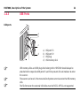
1.4.3
USB Ports
USB ports
a
b
c
d
HDS7000_012
)
)
)
a)
b)
c)
d)
USB
USB
USB
USB
port P1
port P2
plug
memory stick
USB memory sticks and USB plugs that belong to the HDS7000 should always be
attached to the respective USB ports P1 and P2 to prevent dirt and moisture to enter
the scanner.
The scanner can be set in the menu to directly store current scans to the USB memory
stick.
The file format on the external USB sticks must be FAT32. NTFS is not supported.
Caution
Eject the USB memory sticks by pushing the corresponding buttons
before
removing them. Do not remove the USB memory sticks as long as the symbols
are displayed.
HDS7000, Description of the System
25
26
HDS7000, Description of the System
1.5
Field of View (FOV)
Field of view
The HDS7000 has a rotating mirror system that covers a 360 x 320 degree field of
view.
320°
HD
S70
00000
HDS7000_013
20°
20°
360°
1.6
HDS Cyclone Software Suite
General
Leica Geosystems HDS Cyclone software modules provide point cloud users with the
widest set of work process options for 3D laser scanning projects in engineering,
surveying, construction and related applications.
The Software consist of five packages:
• Cyclone Scan:
allows the user to control the Scanner.
• Cyclone Register:
allows the user to register multiple Scans together or to Geo-reference the point
cloud.
• Cyclone Survey:
gives the user basic functionality to extract and measure information from point
clouds.
• Cyclone Model:
gives the user the full functionality of Cyclone. The user is able to extract and
measure features and to create a 3D Model out of the point clouds.
• Cyclone Publisher:
allows users to publish point cloud data to a panoramic viewing format which can
be posted to the Web. Users can then view this data using the Internet Explorer
plug-in Leica TruView.
HDS7000, Description of the System
27
HDS7000, Description of the System
)
•
•
General Operating
Principles
•
•
For more information on Cyclone Software Suite, please visit:
http://www.leica-geosystems.com/hds
Cyclone Software has also an online help available which can be accessed
through the F1 key on your keyboard.
Download:
Cyclone Software, as well as important Support documentation, can be downloaded from the Leica Geosystems HDS Website
(http://www.leica-geosystems.com/hds/en/27054.htm).
The User must create an account before the download section is accessible.
Installation:
You must use a Windows account with administrator privileges to install or
upgrade Cyclone, CloudWorx for AutoCAD, CloudWorx for MicroStation, CloudWorx for PDMS or CloudWorx for Intergraph SmartPlant® Review.
1.
2.
3.
4.
•
28
Download the Cyclone Installshield from the website specified above.
Run the Installation file.
Follow the onscreen instructions and select the software you wish to install.
Go to the License Request Page.
Language:
Cyclone's operating Language is English.
HDS7000, Description of the System
29
HDS7000, Setting Up the Instrument
30
2
Setting Up the Instrument
2.1
General Information
Use the tripod
The instrument should always be set up on its tripod. Using the tripod specified for
the scanning system guarantees maximum stability during scanning operations.
)
)
Always set up the instrument on its tripod. Do not set up the instrument directly on
the ground for scanning operations.
It is always recommended to shield the instrument from direct sunlight and avoid
uneven temperatures around the instrument.
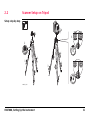
2.2
Scanner Setup on Tripod
Setup step-by-step
HD
S7
000
6
2
5
2
4
4
1
1
3
3
4
1
3
HDS7000_014
HDS7000, Setting Up the Instrument
31
HDS7000, Setting Up the Instrument
)
32
Shield the instrument from direct sunlight and avoid uneven temperatures
around the instrument.
1. Extend the tripod legs to allow for a comfortable working posture. Tighten the
screws at the bottom of the legs.
2. Place the tribrach on the tripod and secure it with the central fixing screw.
3. Set up the tripod so that the tripod plate is as horizontal as possible.
4. Push the tripod legs firmly into the ground.
5. Level up the tribrach using the circular level. Turn two of the foot screws together
in opposite directions. The index finger of your right hand indicates the direction
in which the bubble should move. Now use the third foot screw to centre the
bubble.
6. Place the instrument on the tribrach and secure it with the tribrach’s locking
knob. Make sure that the instrument is levelled by checking the built-in circular
level.
)
)
When placing the instrument on the tribrach, align the legs of the scanner’s
table stand with the foot screws of the tribrach.
It is recommended to setup the HDS7000 horizontally by using the tripod
screws. Subsequently the established horizontation can be refined using
the integrated electronic level. If the incline is more than 0.5°, a warning
appears before scanning.
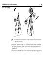
2.3
Setup Over a Benchmark with the Internal Laser Plummet
Description
This topic describes an instrument setup over a marked ground point using the laser
plummet. Geo-referencing of the HDS7000 is established by setting up over a known
or assumed control point, with optional reference target measurement to set the
azimuth direction, and establishing a local or global coordinate system.
The HDS7000 allows you to traverse, resect or free-station. Known azimuth or
known backsight measurements can be observed.
)
)
)
It is always possible to set up the instrument without the need for a marked ground
point.
The data scanned with HDS7000 is corrected by an internal dual-axis compensator,
when the dual-axis compensator is enabled.
•
•
The laser plummet described in this topic is built into the vertical axis of the
instrument. It projects a red spot onto the ground, making it much easier to
centre the instrument.
The laser plummet cannot be used in conjunction with a tribrach equipped with
an optical plummet.
HDS7000, Setting Up the Instrument
33
34
HDS7000, Setting Up the Instrument
Setup step-by-step
f
e
HD
S7
000
g
c
k
d
h
a
a
j
a
b
j
j
i
HDS7000_015
)
Shield the instrument from direct sunlight and avoid uneven temperatures
around the instrument.
1. Extend the tripod legs to allow for a comfortable working posture (a). Position
the tripod approximately over the marked ground point, centring it as well as
possible (b).
2. Place the tribrach on the tripod (c) and secure it with the central fixing screw (d).
3. Place the instrument on the tribrach (e) and secure it with the tribrach’s locking
knob.
4. Turn on the instrument by pressing the ON/OFF button (f). Go to Level, Laser
Plummet and activate the laser plummet (g).
5. Move the tripod legs (a) and use the tribrach footscrews (h) to centre the
plummet (i) over the ground point.
6. Adjust the tripod legs (j) to level the circular level (k).
7. By using the electronic level (Level) turn the tribrach footscrews (h) to precisely
level the instrument.
8. Centre the instrument precisely over the ground point (i) by shifting the tribrach
on the tripod plate.
9. Repeat steps 7. and 8. until the required accuracy is achieved.
HDS7000, Setting Up the Instrument
35
36
HDS7000, Setting Up the Instrument
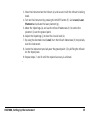
2.4
Instrument Height
Measure instrument height
HD
1
2
3
148
149
150
151
152
153
S7
HDS7000_016
000
To get an accurate measurement, hold
the end of measurement tape with your
foot on benchmark. Now expand the
measurement tape and read height using
bottom line on unit as shown.
)
Take care to use a 1:1 measure,
not a special tape that is scaled
differently (used for common
surveying instruments).
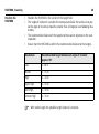
2.5
Set up the tripod
with the dolly
Setting Up the Instrument with the Dolly
1. Fold the dolly apart.
2. Assemble the dolly triangle and secure it
with the screw.
3. Extend the tripod legs to an even length.
4. Fix the tripod legs.
5. Position the legs into the respective
seats on the dolly triangle.
6. Secure the tripod legs with the respective securing strap of each set
)
4
3
6
The dolly is available as an optional
accessory and is not part of the
standard scope of delivery.
1
2
5
6
6
HDS7000_017
HDS7000, Setting Up the Instrument
37
38
HDS7000, Scanning
3
Scanning
3.1
Switching the System On/Off
Switch on procedure
1. Setup the instrument as desired. Refer to chapter "2 Setting Up the Instrument"
for more information.
2. Check that the lens is clean.
3. Press and hold the ON/OFF button for a minimum of 0.3 seconds.
4. The power-up process starts and requires approximately 20 seconds to
complete. During the power-up process the vertical mirror will spin.
5. The system menu is shown on the display.
6. An audible signal sounds.
Switch off procedure
•
•
)
In the event of a system crash, press the ON / OFF button for at least 5 seconds. The
system switches itself off.
Press and hold the ON/OFF button for a minimum 0.5 seconds.
The display shows Shut down system. Please wait.
3.2
Preparations
Targets
•
•
•
•
•
•
•
•
HDS7000, Scanning
Checkerboard pattern
Use non-reflective targets
Use non-reflective target mounting and devices (such as adhesive strips or
holders)
Good recognizable labeling
Distribute the targets over the scanning area at different elevations
Have at least three targets per scan
For best results use the 6" Leica grey and white tilt-and-turn targets.
For printed paper targets use white paper and laser printers only. Test your printouts prior to using them in the field.
39
40
HDS7000, Scanning
Position the
HDS7000
•
•
•
•
Position the HDS7000 in the center of the target field.
The "angle of incidence" is smaller the more perpendicular the surface is to you,
so the angle of incidence should be smaller than 45 degrees (see following illustration).
The recommended distance of the targets to the scanner depends on the scan
resolution.
Ensure that the HDS7000 is within the recommended distance to the targets.
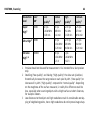
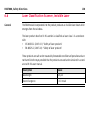
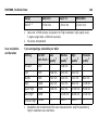
Resolution
Recommended target distance at angle of incident
approx. 90°
Low
1 -10 m
Middle
1 - 15 m
High
1 - 20 m
Super High
1 - 25 m
Ultra High
1 - 30 m
Extreme High
1 - 35 m
)
With smaller angle the possible target distance is reduced.
Target distance
<45°
00
S70
HD
HDS7000_018
HDS7000, Scanning
41
42
HDS7000, Scanning
3.3
Ambient Conditions
Unfavorable
surfaces
•
•
•
Unfavourable
weather conditions
Highly reflective (polished metal, gloss paint)
Highly absorbent (black)
Translucent (clear glass)
)
)
Color or powder these surfaces before scanning.
•
•
•
Rain, snow or fog cause poor measurements, so it is not possible to
survey during these conditions!
Surfaces that are directly illuminated by the sun have an increased range
noise and therefore a larger measurement uncertainty.
If some objects are scanned against the sunlight or a bright spotlight, the
optical receiver of the instrument can be dazzled so heavily that in this
area no measured data is recorded. A "black hole" appears in the reflectance image.
Temperature too
low or too high
)
•
•
•
Mirror
Memory capacity
HDS7000, Scanning
)
)
If the temperature is outside the specified range, an error message is
displayed. Scanning is still possible, but the measuring accuracy is no
longer within specification.
Precaution: Warm up / cool down the instrument.
To avoid damages of the electronics, the instrument switches off when
the upper temperature limit is exceeded.
Precaution: Cool down the instrument in a cold place.
If the instrument is brought from a cold environment (e.g., from storage)
into a warm and humid environment, the glass window at the mirror or in
extreme case even the interior optics can fog up. This causes measurement errors.
Precaution: Avoid large temperature differences; give the instrument
time to acclimate.
Soiling at the glass pane of the mirror, such as a layer of dust, condensed
water or fingerprints, causes considerable measuring errors.
Before initiating the scanning process check if there is enough space on the
internal flash disk (30 – 60 GB per day, depending on your planning).
43
HDS7000, Scanning
Others
Cyclone-SCAN
44
)
Keep field notes containing:
• Target positions relative to the instrument.
• Position of the instrument within the measured area (such as the factory
or shed plan).
The Cyclone SCAN software controls scanning operations with the instrument and
allows point cloud visualization and measurement.
)
Refer to the Cyclone help system for information about the connection of the
instrument to Cyclone and further scanning operations.
3.4
Onboard Controls
To control the HDS7000 via the touch
screen a special stylus is required which is
located directly at the scanner in the
designated slot and can be removed for
operation.
Stylus for touch
screen
HDS7000_019
)
•
•
•
•
•
HDS7000, Scanning
Clicking on a symbol or button opens a menu or executes a command.
Keep the pen on a symbol for more than 0.5 seconds to show a tooltip with
further information on the respective button or parameter.
The horizontal motor of the instrument can be arrested to enable data input with
the stylus without instrument rotation. The motor is released automatically after
5 seconds without any further user interaction or with a scan start.
By clicking the release symbol in the status bar the motor can be released immediately.
The most important scanning menus can also be operated with a finger touch.
The resistive touch screen reacts on pressure, therefore you can also operate the
scanner wearing gloves.
45
46
HDS7000, Scanning
Overview display
a
b
c
a) Status bar
b) Screen area
c) Command bar
HDS7000_020
Element
Description
Status bar
Shows current status information for the instrument.
Screen area
Working area of the screen.
Command bar
Shows available commands of the current screen.
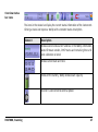
Overview status
bar icons
The icons in the status bar display the current status information of the instrument.
Clicking a status icon opens a tooltip with a detailed status description.
Element
Description
Shows scanner status and IP address. In the tooltip information
about firmware version, DHCP status and remaining time until
next calibration is listed.
Shows current date and time.
Status of the battery, tooltip shows exact capacity.
Scanner is connected to external power.
HDS7000, Scanning
47
48
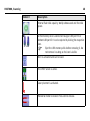
HDS7000, Scanning
Element
Description
Internal flash disk capacity, tooltip shows used and free disk
space.
A USB memory stick is connected to upper USB port P1 or
bottom USB port P2. It can be ejected by clicking the respective
icon.
Eject the USB memory stick before removing it. Do
not remove it as long as the icon is visible.
)
Wi-Fi is activated and can be used.
The DHCP server is active.
Laser plummet is activated.
Horizontal motor is locked. Press icon to release.
Element
Description
Shows the current menu, for example "Home".
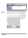
Overview user
input
HDS7000, Scanning
When an numeric or
alphanumeric input field
is selected with the
stylus, a virtual keyboard
opens offering letters,
numbers and special
characters.
49
50
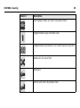
HDS7000, Scanning
Element
Description
Quit keyboard mode and return to previous menu.
Toggle between upper and lower case.
Toggle between alphanumeric and numeric/special characters.
Delete all in the input field.
Backspace.
Confirm and return to previous menu.
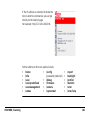
3.5
Main Menu
The main menu is
displayed after the
system boot process.
Description
HDS7000, Scanning
Icon
Description
Scanning
Offers access to all commands for scanner operation
control.
51
52
HDS7000, Scanning
Icon
Description
Scans
Offers access to all commands for scan management.
Help
Offers access to the online help menu.
Brightness
Decrease or increase the brightness of the screen.
Status
Show current scanner status.
Settings
Offers access to the scanner settings.
Hardware
Offers access to hardware settings.
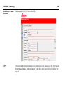
3.6
Scanning
Access
Select Main Menu, Scanning
Description
In the Scanning menu all commands for scanner setup and scan parameters are
available.
HDS7000, Scanning
.
53
54
HDS7000, Scanning
Scanning screen
Icon
Description
Level
Open the Level menu to control the digital bubble and
the laser plummet.
HDS7000, Scanning
Icon
Description
Scan predefined
Quick-Scan button to start a scan with predefined
parameters.
Scan
Open the setup menu for scan parameters.
Profiler
Open the setup menu for scanning in 2D profiling
mode.
Panorama
Open the menu for panoramic image acquisition with
an external camera.
1-TO
Open the One Target Orientation menu for scanner
setup and orientation by known points.
Exit
Close and return to previous menu.
55
56
HDS7000, Scanning
Icon
Description
Setup
Setup the parameters for a predefined scanning.
3.6.1
Level
Access
Select Main Menu, Level
Description
In the Level menu the digital bubble and the laser plummet can be controlled.
.
Level screen
HDS7000, Scanning
57
58
HDS7000, Scanning
)
Icon
Description
Rotate 180°
Rotate the scanner horizontally by 180°.
Justify
Turn the scanner horizontally to 0° and 180° and then
calculate the tilt sensor's zero point (X0,Y0).
Plummet
Turn the laser plummet on/off. By default the laser
plummet is off after system boot.
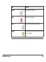
Bubble colour
Description
Green
Tilt < 0.1°
Blue
Tilt < 0.5°
Blue
Tilt < 1.0°
Red
Tilt
1.0°
The digital bubble has to be turned off if the scanner is used in upside-down mode
or if tilted more than 10°.
3.6.2
Start Predefined Scan
Access
Select Main Menu, Scan predefined
Description
In the menu Scan predefined a scan is started with predefined settings as defined
in the menu Setup (refer to "3.6.7 Setup a Predefined Scan"). The button works like
a quick-scan-button without any further configuration needed.
HDS7000, Scanning
.
59
60
HDS7000, Scanning
3.6.3
Scan with User Defined Settings
Access
Select Main Menu, Scan
Description
In the Scan menu all parameters for a user defined scan can be set.
Scan screen
.
HDS7000, Scanning
Field
Description
File
Enter file name of current scan. If file name is not changed, then
next scan is named identically with the appendix increased by 1.
Destination
Select internal flash drive or external USB memory stick as
storage medium for next scan.
Path
Create a folder on the chosen storage medium where to safe the
scan.
Project
Enter project name. Scans will be collected in one .PRJ project file.
Scanposition
Define a scan position. Mark scans from an equal scan position
with the equal scan position name.
Resolution
Select the scan resolution by pressing the +/- buttons or the
slider.
Quality
Select the scan quality by pressing the +/- buttons or the slider.
Level
Enable or disable the electronic level to monitor scanner movement during the scan process and overall inclination of the
instrument.
Camera
Select optional camera. Setting is off by default.
61
62
HDS7000, Scanning
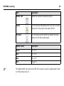
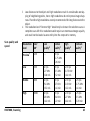
Scanning resolution
Resolution Increments Point
Pixel/
level
(Hz / V)
spacing at 360°
10 m
ZFS file size
Ideal object
(compressed)2 distance
Preview1
0.288° /
0.288°
50.3 mm
1250
ca. 4 MB
> 0.5 m
Low
0.144° /
0.144°
25.1 mm
2500
ca. 15 MB
>1m
Middle
0.072° /
0.072°
12.6 mm
5000
ca. 60 MB
>2m
High
0.036° /
0.036°
6.3 mm
10000
ca. 240 MB
>5m
Super
0.018° /
0.018°
3.1 mm
20000
ca. 960 MB
> 20 m
Ultra High3 0.009° /
0.009°
1.6 mm
40000
ca. 5 GB
> 40 m
Extreme
0.6 mm
100000 ca. 34 GB
High3
High3, 4
1
2
0.004° /
0.004°
3
> 100 m
Preview should not be used for measurement. It is intended for a fast preview
only.
The file size depends on the compression rate.
3
4
Scan quality and
speed
HDS7000, Scanning
Low distances to the object and high resolutions result in considerable overlapping of neighboring points, hence high resolutions do not improve image sharpness. Therefore high resolutions are only recommended for long distances to the
object.
The resolution level “Extreme High” should only be chosen for selection scans. A
complete scan with this resolution would require an enormous storage capacity
and could not be loaded as one entity into the computer’s memory.
Resolution Pixel/
level
360°
Low
Normal
High
Premium
quality2
quality2
quality2
quality2
Preview1
1250
---
25 rps
31.75 KHz
0:26 min
---
---
Low
2500
50 rps
127 KHz
0:26 min
25 rps
63.5 KHz
0:52 min
12.5 rps
31.75 KHz
1:44 min
---
Middle
5000
50 rps
254 KHz
0:52 min
25 rps
127 KHz
1:44 min
12.5 rps
63.5 KHz
3:22 min
6.25 rps
31.75 KHz
6:44 min
High
10000
50 rps
508 KHz
1:44 min
25 rps
254 KHz
3:22 min
12.5 rps
127 KHz
6:44 min
6.25 rps
63.5 KHz
13:28 min
63
64
HDS7000, Scanning
Resolution Pixel/
level
360°
Low
Normal
High
Premium
quality2
quality2
quality2
quality2
Super
High3
50 rps
1.016 MHz
3:28 min
25 rps
508 KHz
6:44 min
12.5 rps
254 KHz
13:28 min
6.25 rps
127 KHz
26:56 min
Ultra High3 40000
---
25 rps
1.016 MHz
13:28 min
12.5 rps
508 KHz
26:56 min
6.25 rps
254 KHz
53:20 min
Extreme
---
10 rps
1.016 MHz
1:21 h
5 rps
1.016 MHz
2:42 h
---
High3, 4
1
2
3
20000
100000
Preview should not be used for measurement. It is intended for a fast preview
only.
Doubling (“low quality”) and halving (“high quality”) the data rate (pixel/sec.)
theoretically increases the range noise on each pixel by 40% (“low quality”) or
decreases it by 40% (“high quality”) compared to “normal quality”. Depending
on the roughness of the surface measured, in reality this difference could be
less, especially when scanning objects with a bright surface at short distances,
for example indoors.
Low distances to the object and high resolutions result in considerable overlapping of neighboring points, hence high resolutions do not improve image sharp-
4
Advanced scan
screen
HDS7000, Scanning
ness. Therefore high resolutions are only recommended for long distances to the
object.
The resolution level “Extreme High” should only be chosen for selection scans. A
complete scan with this resolution would require an enormous storage capacity
and could not be loaded as one entity into the computer’s memory.
By clicking Advanced an advanced scan menu with additional settings can be
accessed.
65
66
HDS7000, Scanning
Predefined vertical
scan range
Field
Description
Comment
Enter additional information to be stored in the scan
header.
Operator
Enter operator details to be stored in the scan header.
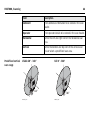
Horizontal
Define the left and right limit of the horizontal scan
area.
Vertical
Define the bottom and top limit of the vertical scan
area or select a predefined scan area.
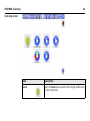
Visible 20° - 340°
Full 0° - 360°
340°
HDS7000_020
360°
HDS7000_021
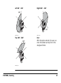
Left 20° - 180°
Right 180° - 340°
180°
HD
S7
000
340°
HDS7000_022
HDS7000_023
Top 100° - 260°
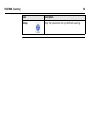
User
With this option selected, the user can
enter the bottom and top limit in the
designated fields.
260°
HD
S7
000
HDS7000_024
HDS7000, Scanning
67
68
HDS7000, Scanning
3.6.4
Profile Scanning
Access
Select Main Menu, Profiler
Description
In the menu Profiler the settings for the 2D profiling mode can be controlled. In
profile scanning the horizontal motor is blocked and only the vertical mirror rotates.
In this mode the scanner typically is mounted on a moving vehicle and the horizontal
rotation is replaced by a forward motion. To determine the trajectory of the motion
additional sensors are required. A special manual is available for this operation mode.
.
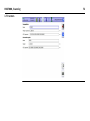
3.6.5
Panorama
Access
Select Main Menu, Panorama
Description
In the menu Panorama panoramic images with an external camera can be created.
.
Panorama screen
HDS7000, Scanning
69
HDS7000, Scanning
)
70
Requires external software (e.g. PTGui) to stitch single images to a full panoramic
image.
3.6.6
One Target Orientation (1-TO)
Access
Select Main Menu, 1-TO
Description
In the 1-TO menu the settings of the One Target Orientation can be made. The user
can enter coordinates, heights and names of a known scanner position and a known
target position for an offline calculation of scanner setup and orientation by known
points.
HDS7000, Scanning
.
71
HDS7000, Scanning
1-TO screen
72
3.6.7
Setup a Predefined Scan
Access
Select Main Menu, Setup
Description
In the Setup menu the settings for the quick-scan-button (refer to "3.6.2 Start
Predefined Scan") can be defined. The settings are the same as for a user-defined
scan (refer to "3.6.3 Scan with User Defined Settings").
In addition the parameters for the quick-scan-button can be protected by a password
here.
HDS7000, Scanning
.
73
74
HDS7000, Scanning
3.7
Scans
Access
Select Main Menu, Scans
Description
In the Scans menu all commands for scan management are available such as copy,
move, delete and display scans.
.
Scan folder screen
HDS7000, Scanning
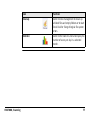
Icon
Function
Internal / USB P1/ USB P2
Select access to internal flash drive or to
external USB memory stick.
75
76
HDS7000, Scanning
Icon
Function
Root folder
Go to root folder of selected drive.
Up / Down
Navigate up or down in the folder list.
Go to first /
last
Navigate to the first or last folder in the
list.
Expand
Expand selected folder.
Scans
List all scans of the selected folder.
Manage
Switch to scan management to copy, move
or delete scans.
HDS7000, Scanning
Icon
Function
Cleanup
Switch to disk management to clean up
unlinked files and empty folders or to start
Check Disk for fixing of logical file system
errors.
Statistic
Switch to the Statictics menu to display the
number of scans per day in a selected
month.
77
78
HDS7000, Scanning
Scans screen
Icon
Function
Folder
Shows the selected folder.
Up / Down
Navigate up or down in the scan list.
HDS7000, Scanning
Icon
Function
Go to first /
last
Navigate to the first or last scan in the list.
View
Open view mode and show selected scan on
display.
79
80
HDS7000, Scanning
View screen
Icon
Function
Mode
Toggle between movement, selection and measurement mode.
HDS7000, Scanning
Icon
Function
Label
In selection mode create a text label at cursor position.
Distance
In measurement mode get the distance between two
points.
Undo
Undo the last user command for movement, labeling or
selection.
View
Toggle between 2D, bubble and info view.
Grid
In movement mode display/hide a grid.
Zoom in
Zoom in to see details of the selected scan.
81
82
HDS7000, Scanning
Icon
Function
Zoom out
Zoom out to get a better overview of the selected
scan.
3.8
Help
Access
Select Main Menu, Help
Description
In the Help menu online help files and support contacts can be found.
HDS7000, Scanning
.
83
84
HDS7000, Scanning
3.9
Status
Access
Select Main Menu, Status
Description
In the Status menu the current scanner status and potential errors are displayed.
Status screen
.
HDS7000, Scanning
Icon
Function
Ignore
Confirm error and proceed.
Abort
Confirm error and abort.
Help
Open help menu with support contacts.
Report
Create a report file and store it on USB memory
stick if connected.
85
86
HDS7000, Scanning
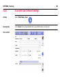
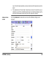
3.10
Settings
Access
Select Main Menu, Settings
Description
In the Settings menu the instrument can be configured by changing settings for
language, units, date/time or the IP address.
.
Settings screen
)
HDS7000, Scanning
Settings marked with “*1” require a scanner restart to take effect.
87
88
HDS7000, Scanning
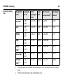
Field
Description
Language
Select operating language (English, German, Spanish,
French, Italian, Japanese, Dutch, Russian, Portuguese,
Chinese).
Unit
Select unit for distances (meter, foot, foot + inch,
yard).
Date/Time
Set local date and time and confirm with
“Apply+switchoff”. After confirmation the scanner
switches off and must be rebooted.
DHCP Client
Choose if a DHCP client is used.
DHCP server
Choose if a DHCP server is used.
IP
Change the scanner’s IP address.
Wireless
Select for Wi-Fi operation.
Key (WPA2)
Enter password for WPA2 protection of Wi-Fi communication.
m-cam
Enable the graycard function of the m-cam.
3.11
Hardware
Access
Select Main Menu, Hardware
Description
In the Hardware menu information about internal and external hardware components is displayed.
HDS7000, Scanning
.
89
90
HDS7000, Scanning
Hardware screen
Icon
Function
Calib Touch
Open touch screen calibration.
Level
Open the Level menu to control the digital bubble and
the laser plummet.
HDS7000, Scanning
Icon
Function
Warmup
Warm up the scanner by powering up (lubrication
solvent liquefies) the motors and electronic parts.
M-Cam
Check status and upload calibration parameters of an
optional m-cam camera.
Digi-Cam
Detect and check status of an optional digital camera.
GPS
Check functionally of an optional attached GPS.
Motor
Check functionality of horizontal and vertical motors.
Connector
Test input and output signals of lemo connectors P3
and P4.
91
92
HDS7000, Scanning
3.12
Connections
Description
The HDS7000 is equipped with an a network interface and a Wi-Fi interface to allow
external control.
Cable connection
Wi-Fi connection
HDS7000
HDS7000
HDS7000_025
HDS7000_026
In order for a notebook/PC and the HDS7000 to communicate with one another, each
of the devices must be able to send data to the other (network). So that this data
arrives at the right station, the station must have a unique address. In an IP network
this is achieved with an IP address.
The HDS7000 supports DHCP (Dynamic Host Configuration Protocol). If the automatic reference to an IP address is set at the client (DHCP client), the HDS7000 can
be included in any network without further configuration.
A DHCP server on the network automatically assigns an IP address to the DHCP client
(HDS7000).
If the HDS7000 is connected by an Ethernet cable only to a notebook, without a
wider network structure, then the HDS7000 is a DHCP server. The HDS7000 assigns
a dynamic IP address to the notebook/PC on start-up.
)
HDS7000, Scanning
If there is no DHCP the user must enter the IP address and netmask.
93
94
HDS7000, Scanning
3.12.1
Connecting the HDS7000 to a Network by Cable
Access
Select Main Menu, Settings
Description
In the Settings menu enable the DHCP Client option for a connection to a network.
.
Connecting by
cable
HDS7000, Scanning
1. Connect the HDS7000 with the attached Ethernet cable to a hub/switch on the
desired network.
2. Settings on the HDS7000:
• Switch on the HDS7000 (press the ON/OFF button for 0.3 sec).
• Go to Main Menu, Settings and enable DHCP Client.
• Reboot the HDS7000.
3. Settings on your browser:
• Open the web browser on your notebook/PC.
• Select Tools/Internet Options/Connections/LAN Settings/Advanced.
• Select under exceptions Do not use a proxy server.
• Confirm all changes in your web browser.
• Enter the IP of the HDS7000 into your web browser.
For example 172.20.0.100
95
96
HDS7000, Scanning
3.12.2
Connecting the HDS7000 to a Notebook by Cable
Access
Select Main Menu, Settings
Description
In the Settings menu enable the DHCP Server option for a connection to a notebook.
.
Connecting to the
notebook
HDS7000, Scanning
1. Connect the HDS7000 to the notebook with the attached Ethernet cable. The
LAN connection should be automatically activated in the PC otherwise the
attributes of the LAN connection could be shown by choosing network connections. Set a check mark at Internet Protocol (TCP/IP) and open the attributes. In
attributes the field Source IP address automatically and Source DNS address
automatically should be checked.
2. Settings on the HDS7000:
• Switch on the HDS7000 (press the ON/OFF button for 0.3 sec).
• Go to Main Menu, Settings and enable DHCP Server.
• Reboot the HDS7000.
3. Settings on the notebook:
On the notebook you can access the data on the HDS7000 using the web
browser or an FTP client:
• Enter the IP address of the HDS7000 into your web browser: http://<IP>
or
• Enter the IP address directly at the FTP client.
The scan files on the HDS7000’s hard disk are listed in their subfolders in the web
browser/FTP client. When using the web browser a preview of every scan is shown.
You can open the scan files or download them to your notebook.
97
98
HDS7000, Scanning
)
•
•
•
The firewall of the notebook should be deactivated to avoid disturbing the
connection to the scanner.
The proxy settings of the web browser should be deactivated or an exception for
the web page must be declared.
Enter user name “scans” for establishing an FTP connection to be able to delete
scans. Backup all important files before deleting. Deleted files cannot be
restored.
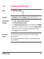
3.12.3
Connecting the HDS7000 by Wi-Fi
Access
Select Main Menu, Settings
Description
In the Settings menu enable the Wireless option for a Wi-Fi connection.
Configuration of
the laptop
Web browser
settings
HDS7000, Scanning
.
1. Go to Start, Settings, Network Connections.
2. Select Wireless Network Connections.
3. In the Wireless Network Connections list the HDS7000 is listed as hds7000xxxx with xxxx = serial number. If scanner is not listed select Refresh network
list, after some seconds the system automatically will find the HDS7000.
4. Press Connect to connect the HDS7000.
Open your web browser and in the address field enter the Wi-Fi IP address
http://192.168.3.1
In Wi-Fi mode the general IP address 192.168.3.1 is used instead of the unique
scanner IP address.
99
100
HDS7000, Scanning
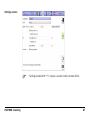
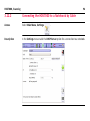
3.13
Operating the HDS7000 using a Web Browser
Start page
The HDS7000 can be operated via Ethernet connection or via Wi-Fi in a local network
directly using a web browser.
Enter the IP address of the HDS7000 into
the address field of your web browser.
Refer to IP address under "3.10 Settings".
The functions of the main menu are
displayed.
For example: http://172.20.0.100
Fixed address for Wi-Fi:
http://192.168.3.1
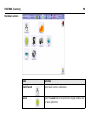
The buttons on the left side of the screen guide directly to the following menu items:
• Scan
• Info
• Scanmanagement
• Status
• Help
• Scan predefined
If the IP address is extended to show the
menu’s shortcut commands, you can go
directly to the desired page.
For example: http//172.20.0.100/info
Further shortcuts for menu points include:
•
•
•
•
•
•
HDS7000, Scanning
/home
/info
/scan
/scan/predefined
/scanmanagement
/status
•
•
•
•
•
/config
(password protected)
/debug
/firmware
/camera
/systemtest
•
•
•
•
•
•
/report
/backlight
/profiler
/statistic
/error
/error/help
101
102
HDS7000, Scanning
Scan menu in web
browser
)
For example: http//172.20.0.100/info
The settings for the web browser scan interface are the same as for the interface of
the onboard display. Refer to chapter "3.6.3 Scan with User Defined Settings" for
details.
HDS7000, Scanning
103
104
HDS7000, Troubleshooting
4
HDS7000
Troubleshooting
Problem
Instrument does not
boot.
Missing points in
scans.
Possible Cause(s)
Suggested Remedies
Disconnect from AC power
supply or external battery.
Disconnect all cables and
remove all internal batteries.
Wait for 1 minute. Reconnect
cables and external power
sources, insert all internal
batteries and switch on again.
Dust, debris or fingerprints Use glass cleaning kit to clean
on optics of rotating mirror. the specific areas.
Instrument too cold. The instrument is operated Start scanning, for example
at a temperature lower
perform some preview scans, as
than -10°C.
the activity helps warm the
HDS7000.
Instrument too
warm.
The instrument is operated Put the HDS7000 in a cool and
shady place, leave it powered in
at a temperature higher
than +45°C.
standby mode only.
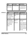
HDS7000 Battery
Problem
Possible Cause(s)
Suggested Remedies
Control panel does
not work correctly.
Dirt on the touch screen.
Turn off the instrument and
clean control panel with mild
cleaning supplies and a soft
tissue.
Problem
Possible Cause(s)
Suggested Remedies
When switching on the
instrument or starting a
scan, the system switches
off automatically.
Capacity of battery is
too low.
Recharge or change battery.
When switching on the
instrument or starting a
scan, the system switches
off automatically even
though it was totally
recharged.
Battery charger is
defective.
Check the function of the
battery charger.
Damaged cable.
Examine the cabling and pay
attention to damages, which
for example can cause loose
contacts or short circuits.
Defective circuits need to be
replaced. Only use supplied
power cables.
HDS7000, Troubleshooting
105
106
HDS7000, Troubleshooting
Problem
HDS7000 battery
charging process
Problem
Possible Cause(s)
Suggested Remedies
Internal battery is no
longer charging.
At the end of its life time the
internal battery has lost most
of its capacity. The battery
needs to be replaced.
Possible Cause(s)
Charging status on
Battery is depth-discharged
charging cradle is not and the charger cannot
shown and running
initialize.
light is active.
Battery is defect.
Suggested Remedies
Turn off power supply and turn
it on again without changing
any configuration.
Test with another battery. If
needed replace defect battery.
Red LED flashing
rapidly on the
charging cradle.
Charging cradle and battery Use the charging cradle and the
operated outside the oper- battery for charging only at
ation temperature (0°C to temperature from 0°C to 40°C.
+40°C).
Red LED flashing
slowly on the
charging cradle.
Charging process too slow. Check with another battery.
Charger cannot load
battery in given time.
Report file procedure
The report file procedure explains how to create a report file with the user interface
of your HDS7000 instrument in case of problems with the scanner. To create a report
file, follow the steps described below:
1. Go to Main Menu, Status, Report to create a report file.
2. Copy the report file from the internal or external disk.
3. Send the report file together with details about scanner type, scanner serial
number and a short description of the problem to your local support team.
Summary
If you experience problems with your instrument email the scanner's report file to
your local support:
• For Americas support:
[email protected]
• For Europe, Middle East and Africa support:
[email protected]
• For Asia support:
[email protected]
HDS7000, Troubleshooting
107
HDS7000, Care and Transport
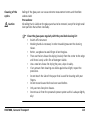
5
Care and Transport
5.1
Check & Adjust
Caution
108
Units that are exposed to high mechanical forces, e.g. through frequent transport or
rough handling, it is recommended to carry out a check and adjust twice a year by
the manufacturer respectively just after such a high stress exposure.
5.2
Transport
Transport
in the field
When transporting the equipment in the field, always make sure that you
• either carry the product in its original transport container,
• or carry the tripod with its legs splayed across your shoulder, keeping the
attached product upright.
Transport
in a road vehicle
Never carry the product loose in a road vehicle, as it can be affected by shock and
vibration. Always carry the product in its transport container and secure it.
Shipping
When transporting the product by rail, air or sea, always use the complete original
Leica Geosystems packaging, transport container and cardboard box, or its equivalent, to protect against shock and vibration.
Shipping, transport
of batteries
When transporting or shipping batteries, the person in charge of the product must
ensure that the applicable national and international rules and regulations are
observed. Before transportation or shipping, contact your local passenger or freight
transport company.
HDS7000, Care and Transport
109
HDS7000, Care and Transport
110
5.3
Storage
Product
Respect the temperature limits when storing the equipment, particularly in summer
if the equipment is inside a vehicle. Refer to "7 Technical Data" for information about
temperature limits.
Field adjustment
After long periods of storage, inspect the field adjustment parameters given in this
user manual before using the product.
Batteries
•
•
•
•
•
•
Refer to "7.4 Environmental" for information about storage temperature range.
A storage temperature range of -20°C to +30C / -4°F to +86°F in a dry environment is recommended to minimize self-discharging of the battery.
At the recommended storage temperature range, batteries containing a 10% to
50% charge can be stored for up to one year. After this storage period the
batteries must be recharged. The batteries have to be recharged after maximum
6 month.
Remove batteries from the product and the charger before storing.
After storage, recharge batteries before using.
Protect batteries from damp and wetness. Wet or damp batteries must be dried
before storing or use.
5.4
Cleaning and Drying
Product and accessories
•
•
•
•
Use only a clean, soft, lint-free cloth for cleaning or use lens paper (e.g. for
cleaning camera lenses). If necessary, moisten the cloth with water or pure
alcohol. Do not use other liquids; these may attack the polymer components.
Blow dust off glass windows.
Never touch the glass with your fingers.
Never clean glass with paper towels or similar, as they will scratch the coating on
the windows.
Damp products
Dry the product, the transport container, the foam inserts and the accessories at a
temperature not greater than +40°C / +104°F and clean them. Do not repack until
everything is completely dry. Always close the transport container when using in the
field.
Cables and plugs
Keep plugs clean and dry. Blow away any dirt lodged in the plugs of the connecting
cables.
HDS7000, Care and Transport
111
HDS7000, Care and Transport
5.5
Window Cleaning Procedure
General
The HDS7000 scanning window must be kept clean. The instructions must be
followed as described in this chapter to clean the scanner mirror.
Warning
112
Direct intrabeam viewing is always hazardous.
Precautions:
Before cleaning windows, ensure the instrument is switched off.
)
Window Cleaning Kit can be ordered through your local Leica Geosystems dealer.
Dust and debris
removal
Using a compressed gas duster (e.g., UltraJet ®2000 Gas Duster or UltraJet®
Compressed CO2 Duster), remove dust and debris from surface of scanner windows.
)
Never rub off dust or debris as this will scratch the windows and so possibly cause
permanent damage to the special optical coatings.
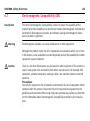
Cleaning of the
optics
Caution
Soiling of the glass pane can cause extreme measurement errors and therefore
useless data!
Precautions:
All soiling that is visible on the glass pane has to be removed, except for single small
dust particles that adhere inevitably.
)
Clean the glass pane regularly with the provided cleaning kit:
• Switch off instrument.
• Washing hands is necessary in order to avoid grease on the cleaning
tissue.
• Better, use gloves to avoid finger oil on the glass.
• Then use the lens tissue for wiping circularly from the center to the edge
until there is only a thin film of detergent visible.
• Use a new lens tissue for drying the pane, wipe circularly.
• If any smears from cleaning are visible against back light, repeat the
procedure.
• Do not touch the side of the paper that is used for cleaning with your
fingers.
• Do not reuse tissues that have been used before.
• Only use non-fuzzy lens tissues.
• Do not use air from the pneumatic power system as this is always slightly
oily!
HDS7000, Care and Transport
113
114
HDS7000, Care and Transport
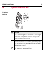
5.6
Adjustment of the Circular Level
On the tribrach
step-by-step
HDS7000_027
Step
Description
1.
Level up the tribrach together with the instrument in advance using the
electronic level, assuming that the instrument is correctly adjusted.
Remove the instrument from the tribrach.
2.
The bubble of the tribrach must be centered. If it extends beyond the
circle, use the adjusting pin in conjunction with the two cross-headed
adjustment screws to centre it.
)
After the adjustment, no screw shall be loose.
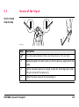
5.7
Service of the Tripod
Service tripod
step-by-step
2
1
3
HDS7000_031
Step
)
Description
The connections between timber and metal must be firm and tight.
1.
Moderately tighten the allen screws (1) with the allen key supplied with the
tripod.
2.
Tighten articulated joints just enough to keep the tripod legs open when
lifting the tripod off the ground (2).
3.
Tighten the allen screws of the tripod legs (3).
HDS7000, Care and Transport
115
HDS7000, Safety Directions
116
6
Safety Directions
6.1
General Description
Description
The following directions should enable the person responsible for the product, and
the person who actually uses the equipment, to anticipate and avoid operational
hazards.
The person responsible for the product must ensure that all users understand these
directions and adhere to them.
6.2
Intended Use
Permitted use
•
•
•
•
•
•
•
•
•
Measuring horizontal and vertical angles.
Measuring distances.
Recording measurements.
Computing by means of software.
Target search, recognition.
Visualizing the aiming direction and vertical axis.
Recording point related data.
Remote control of product.
Data communication with external appliances.
Adverse use
•
•
•
•
•
Use of the product without instruction.
Use outside of the intended limits.
Disabling safety systems.
Removal of hazard notices.
Opening the product using tools, for example screwdriver, unless this is specifically permitted for certain functions.
Modification or conversion of the product.
Use after misappropriation.
Use of products with obviously recognizable damages or defects.
•
•
•
HDS7000, Safety Directions
117
HDS7000, Safety Directions
•
•
•
•
Warning
118
Use with accessories from other manufacturers without the prior explicit
approval of Leica Geosystems.
Inadequate safeguards at the surveying site, for example when measuring on
roads.
Deliberate dazzling of third parties.
Controlling of machines, moving objects or similar monitoring application without
additional control- and safety installations.
Adverse use can lead to injury, malfunction and damage.
It is the task of the person responsible for the equipment to inform the user about
hazards and how to counteract them. The product is not to be operated until the user
has been instructed on how to work with it.
6.3
Limits of Use
Environment
Suitable for use in an atmosphere appropriate for permanent human habitation: not
suitable for use in aggressive or explosive environments.
Danger
Local safety authorities and safety experts must be contacted before working in
hazardous areas, or in close proximity to electrical installations or similar situations
by the person in charge of the product.
HDS7000, Safety Directions
119
HDS7000, Safety Directions
6.4
)
120
Responsibilities
Leica Geosystems AG, Heinrich-Wild-Strasse, CH-9435 Heerbrugg, Switzerland, hereinafter referred to as Leica Geosystems, is responsible for supplying the product,
including the user manual and original accessories, in a completely safe condition.
Manufacturers of
non Leica Geosystems accessories
The manufacturers of non Leica Geosystems accessories for the product are responsible for developing, implementing and communicating safety concepts for their
products, and are also responsible for the effectiveness of those safety concepts in
combination with the Leica Geosystems product.
Person in charge of
the product
The person in charge of the product has the following duties:
• To understand the safety instructions on the product and the instructions in the
user manual.
• To be familiar with local regulations relating to safety and accident prevention.
• To inform Leica Geosystems immediately if the product and the application
becomes unsafe.
• To ensure that the national laws, regulations and conditions for the operation of
radio transmitters are respected
Warning
The person responsible for the product must ensure that it is used in accordance with
the instructions. This person is also accountable for the training and the deployment
of personnel who use the product and for the safety of the equipment in use.
6.5
Warning
Caution
Caution
Hazards of Use
The absence of instruction, or the inadequate imparting of instruction, can lead to
incorrect or adverse use, and can give rise to accidents with far-reaching human,
material, financial and environmental consequences.
Precautions:
All users must follow the safety directions given by the manufacturer and the directions of the person responsible for the product.
Watch out for erroneous measurement results if the product has been dropped or
has been misused, modified, stored for long periods or transported.
Precautions:
Periodically carry out test measurements and perform the field adjustments indicated
in the user manual, particularly after the product has been subjected to abnormal use
and before and after important measurements.
During the operation of the product there is a hazard of squeezing extremities or
entanglement of hairs and/or clothes by rotating parts.
Precautions:
Keep a safe distance of the rotating parts.
HDS7000, Safety Directions
121
HDS7000, Safety Directions
Caution
Danger
Warning
122
With the remote control of products, it is possible that extraneous targets will be
picked out and measured.
Precautions:
When measuring in remote control mode, always check your results for plausibility.
Because of the risk of electrocution, it is very dangerous to use poles and extensions
in the vicinity of electrical installations such as power cables or electrical railways.
Precautions:
Keep at a safe distance from electrical installations. If it is essential to work in this
environment, first contact the safety authorities responsible for the electrical installations and follow their instructions.
By working during a thunderstorm you are at risk from lightning.
Precautions:
Do not carry out field surveys during thunderstorms.
Warning
Warning
Warning
During dynamic applications, for example stakeout procedures, there is a danger of
accidents occurring if the user does not pay attention to the environmental conditions around, for example obstacles, excavations or traffic.
Precautions:
The person responsible for the product must make all users fully aware of the existing
dangers.
Inadequate securing of the working site can lead to dangerous situations, for
example in traffic, on building sites, and at industrial installations.
Precautions:
Always ensure that the working site is adequately secured. Adhere to the regulations
governing safety and accident prevention and road traffic.
If computers intended for use indoors are used in the field there is a danger of electric shock.
Precautions:
Adhere to the instructions given by the computer manufacturer with regard to field
use in conjunction with Leica Geosystems products.
HDS7000, Safety Directions
123
HDS7000, Safety Directions
Caution
Warning
Warning
124
If the accessories used with the product are not properly secured and the product is
subjected to mechanical shock, for example blows or falling, the product may be
damaged or people may sustain injury.
Precautions:
When setting-up the product, make sure that the accessories, for example tripod,
tribrach, connecting cables, are correctly adapted, fitted, secured, and locked in position.
Avoid subjecting the product to mechanical stress.
Only Leica Geosystems authorised service workshops are entitled to repair these
products.
Using a battery charger not recommended by Leica Geosystems can destroy the
batteries. This can cause fire or explosions.
Precautions:
Only use chargers recommended by Leica Geosystems to charge the batteries.
Danger
Warning
Warning
The product is not designed for use under wet and severe conditions. If unit becomes
wet it may cause you to receive an electric shock.
Precautions:
Use the product only in dry environments, for example in buildings or vehicles.
Protect the product against humidity. If the product becomes humid, it must not be
used !
If you open the product, either of the following actions may cause you to receive an
electric shock.
Touching live components
Using the product after incorrect attempts were made to carry out repairs.
Precautions:
Do not open the product. Only Leica Geosystems authorised service workshops are
entitled to repair these products.
Batteries not recommended by Leica Geosystems may be damaged if charged or
discharged. They may burn and explode.
Precautions:
Only charge and discharge batteries recommended by Leica Geosystems.
HDS7000, Safety Directions
125
HDS7000, Safety Directions
Danger
Warning
Warning
Caution
126
If unit is not connected to ground, death or serious injury can occur.
Precautions:
To avoid electric shock power cable and outlet must be grounded.
High mechanical stress, high ambient temperatures or immersion into fluids can
cause leackage, fire or explosions of the batteries.
Precautions:
Protect the batteries from mechanical influences and high ambient temperatures. Do
not drop or immerse batteries into fluids.
Short circuited battery terminals can overheat and cause injury or fire, for example
by storing or transporting in pockets if battery terminals come in contact with jewellery, keys, metallized paper or other metals.
Precautions:
Make sure that the battery terminals do not come into contact with metallic objects.
Direct rain or water may damage and/or reduced lifetime on the battery.
Precautions:
During outdoor use keep the battery in an against rain protected place.
Caution
Warning
Long term storage may reduce lifetime or damage the battery.
Precautions:
During long term storage, maintain battery life by periodic re-charge.
During usage, charging and/or disposal one of the following can occur with impact to
humans and environment:
Explosion hazard:
A highly-explosive oxyhydrogen gas mixture occurs when charging
batteries.
Precautions:
Fires, sparks, naked lights and smoking are prohibited:
Avoid causing sparks when dealing with cables and electrical equipment,
and beware of electrostatic discharges. Avoid short-circuits.
Corrosive hazard:
Battery acid is highly corrosive.
Precautions:
Wear protective gloves and eye protection. Do not tilt battery, acid can
escape from the degassing openings or vents.
HDS7000, Safety Directions
127
HDS7000, Safety Directions
Caution
Warning
Warning
128
During the transport, shipping or disposal of batteries, it is possible for inappropriate
mechanical influences to constitute a fire hazard.
Precautions:
When transporting shipping, or disposing batteries, the person in charge of the
product must ensure that the applicable national and international rules and regulations are observed. Before transportation or shipping contact your local passenger
or freight transport company.
Charging the battery at temperatures below 0°C or above 40°C or operating it at
temperatures below -10°C or above 45°C is not allowed since it may damage the
battery.
Precautions:
Only charge the battery in well-ventilated areas because it can produce explosive
gases. Connect the battery to the battery charger only when the charger is turned
off. Fire, smoking, and sparking near the battery are not allowed.
If charged or discharged, batteries not recommended by Leica Geosystems may be
damaged. They may burn and explode.
Precautions:
Only charge and discharge batteries recommended by Leica Geosystems.
Warning
If the product is improperly disposed of, the following can happen:
• If polymer parts are burnt, poisonous gases are produced which may impair
health.
• If batteries are damaged or are heated strongly, they can explode and cause
poisoning, burning, corrosion or environmental contamination.
• By disposing of the product irresponsibly you may enable unauthorised persons
to use it in contravention of the regulations, exposing themselves and third
parties to the risk of severe injury and rendering the environment liable to
contamination.
• Improper disposal of silicone oil may cause environmental contamination.
Precautions:
The product must not be disposed of with household waste.
Dispose of the product appropriately in accordance with the national
regulations in force in your country.
Always prevent access to the product by unauthorised personnel.
Product specific treatment and waste management information can be downloaded
from the Leica Geosystems home page at
http://www.leica-geosystems.com/treatment or received from your Leica Geosystems
dealer.
HDS7000, Safety Directions
129
130
HDS7000, Safety Directions
6.6
Laser Classification Scanner, Invisible Laser
General
The EDM module incorporated into the product produces an invisible laser beam which
emerges from the windows.
The laser product described in this section is classified as laser class 1 in accordance
with:
• IEC 60825-1 (2007-03): "Safety of laser products"
• EN 60825-1 (2007-10): "Safety of laser products"
These products are safe under reasonably foreseeable conditions of operation and are
not harmful to the eyes provided that the products are used and maintained in accordance with this user manual.
Description
Value
Wavelength
1.5 μm
Beam divergence
< 0.3 mrad
Labelling
Type: HDS7000
Zoller+Fröhlich GmbH
Art.No.:
785833
This device contains
a transmitter:
S.No.:
......
FCC-ID: M4Y-AG623G2
D-88239 Wangen im Allgäu
Power: 24V,
, 2.5A
LASER KLASSE1
DIN EN 60825-1:2008-05
Manufactured: . . . . . .
Made in Germany
Patent No: US 7,190,465 B2
Date of Patent: Mar. 13, 2007
Complies with 21 CFR 1040.10 and 1040.11 except for
deviation pursant to LaserNotice No. 50, dated June 24, 2007
a
This device complies with part 15 of the FCC Rules.
Operation is subject to the following two conditions:
(1) This device may not cause harmful interference, and
(2) this device must accept any interference received,
including interference that may cause undesired operation.
Class 1 Laser Product
according to IEC 60825-1
( 2007 - 03 )
HDS7000_028
a) Laser beam
HDS7000, Safety Directions
131
HDS7000, Safety Directions
132
6.7
Electromagnetic Compatibility EMC
Description
The term Electromagnetic Compatability is taken to mean the capability of the
product to function smoothly in an environment where electromagnetic radiation and
electrostatic discharges are present, and without causing electromagnetic disturbances to other equipment.
Warning
Electromagnetic radiation can cause disturbances in other equipment.
Although the product meets the strict regulations and standards which are in force
in this respect, Leica Geosystems cannot completely exclude the possibility that other
equipment may be disturbed.
Caution
There is a risk that disturbances may be caused in other equipment if the product is
used in conjunction with accessories from other manufacturers, for example field
computers, personal computers, two-way radios, non-standard cables or external
batteries.
Precautions:
Use only the equipment and accessories recommended by Leica Geosystems. When
combined with the product, they meet the strict requirements stipulated by the
guidelines and standards. When using computers and two-way radios, pay attention
to the information about electromagnetic compatibility provided by the manufacturer.
Caution
Warning
Disturbances caused by electromagnetic radiation can result in erroneous measurements.
Although the product meets the strict regulations and standards which are in force
in this respect, Leica Geosystems cannot completely exclude the possibility that the
product may be disturbed by very intense electromagnetic radiation, for example,
near radio transmitters, two-way radios or diesel generators.
Precautions:
Check the plausibility of results obtained under these conditions.
If the product is operated with connecting cables attached at only one of their two
ends, for example external supply cables, interface cables, the permitted level of
electromagnetic radiation may be exceeded and the correct functioning of other
products may be impaired.
Precautions:
While the product is in use, connecting cables, for example product to external
battery, product to computer, must be connected at both ends.
HDS7000, Safety Directions
133
HDS7000, Safety Directions
Warning
134
Electromagnetic radiation can cause disturbances in other equipment, in installations, in medical devices, for example pacemakers or hearing aids and in aircraft. It
can also affect humans and animals.
Precautions:
Although the product meets in combination with radio or digital cellular phone
devices recommended by Leica Geosystems the strict regulations and standards
which are in force in this respect, Leica Geosystems cannot completely exclude the
possibility that other equipment may be disturbed or that humans or animals may be
affected.
• Do not operate the product with radio or digital cellular phone devices in the
vicinity of filling stations or chemical installations, or in other areas where an
explosion hazard exists.
• Do not operate the product with radio or digital cellular phone devices near to
medical equipment.
• Do not operate the product with radio or digital cellular phone devices in aircraft.
• Do not operate the product with radio or digital cellular phone devices for long
periods immediately next to your body.
6.8
FCC Statement, Applicable in U.S.
Applicability
The grayed paragraph below is only applicable for products of the HDS7000 System
without radio, digital cellular phone devices or Bluetooth.
Warning
This equipment has been tested and found to comply with the limits for a Class B
digital device, pursuant to part 15 of the FCC rules.
These limits are designed to provide reasonable protection against harmful interference in a residential installation.
This equipment generates, uses and can radiate radio frequency energy and, if not
installed and used in accordance with the instructions, may cause harmful interference to radio communications. However, there is no guarantee that interference will
not occur in a particular installation.
If this equipment does cause harmful interference to radio or television reception,
which can be determined by turning the equipment off and on, the user is encouraged to try to correct the interference by one or more of the following measures:
•
•
•
Reorient or relocate the receiving antenna.
Increase the separation between the equipment and the receiver.
Connect the equipment into an outlet on a circuit different from that to which
the receiver is connected.
•
Consult the dealer or an experienced radio/TV technician for help.
HDS7000, Safety Directions
135
136
HDS7000, Safety Directions
Warning
Changes or modifications not expressly approved by Leica Geosystems for compliance could void the user's authority to operate the equipment.
Labelling
HDS7000
Type: HDS7000
Zoller+Fröhlich GmbH
Art.No.:
785833
S.No.:
......
This device contains
a transmitter:
FCC-ID: M4Y-AG623G2
D-88239 Wangen im Allgäu
HD
S7
000
HDS7000_032
Power: 24V,
, 2.5A
LASER KLASSE1
DIN EN 60825-1:2008-05
Manufactured: . . . . . .
Made in Germany
Patent No: US 7,190,465 B2
Date of Patent: Mar. 13, 2007
Complies with 21 CFR 1040.10 and 1040.11 except for
deviation pursant to LaserNotice No. 50, dated June 24, 2007
This device complies with part 15 of the FCC Rules.
Operation is subject to the following two conditions:
(1) This device may not cause harmful interference, and
(2) this device must accept any interference received,
including interference that may cause undesired operation.
Labelling
Charging cradle
Type: Li-lon Charger
Zoller+Fröhlich GmbH
Art.No.:
788153
S.No.:
......
D-88239 Wangen im Allgäu
INPUT: 24V, VDC, 5A
OUTPUT: 16.8 VDC, 2 x 2.4 A
Manufactured: . . . . . . . ., Made in Germany
This device complies with part 15 of the FCC Rules. Operation
is subject to the following two conditions:
(1) This device may not cause harmful interference, and
(2) this device must accept any interference received,
including interference that may cause undesired operation.
ER
R
HDS7000_029
HDS7000, Safety Directions
137
138
HDS7000, Safety Directions
Labelling battery
Type: Li-lon Battery
Zoller+Fröhlich GmbH
Art.No.:
785835
D-88239 Wangen im Allgäu
Nominal / Charge Voltage: 14.4V / 16.8A
Energy / Capacity: 2x70.56Wh, 4.9 Ah
Manufactured: . . . . . . . .
Made in Germany
HDS7000_030
S.No.:
......
HDS7000, Safety Directions
139
HDS7000, Technical Data
140
7
Technical Data
7.1
General Technical Data of the Instrument
Instrument
Compact, phase-based, dual-axis compensated, ultra-high speed laser scanner, with
survey-grade accuracy, range, field-of-view and laser plummet.
User interface
Onboard touch panel, notebook PC or PDA
Scanner drive
Servo motor
7.2
Laser Scanning System
Wavelenght/Colour
1.5 μm, invisible
Laser Class
Class 1 (in accordance with IEC 60825-1 resp. EN 60825-1)
Range
Maximum range:
Minimum range:
Range resolution:
Linearity error
187 m ambiguity interval
0.3 m
0.1 mm
1 mm
Spot size
~ 3.5 mm @ 0.1 m distance (Gaussian based)
Beam divergence
< 0.3 mrad
Scan rate
Up to 1'016'000 points/sec, maximum instantaneous rate
Range noise
Range
Black 14%
Gray 37%
White 80%
10 m1
0.5 mm rms
0.4 mm rms
0.3 mm rms
25
m1
1.0 mm rms
0.6 mm rms
0.5 mm rms
50
m1
2.7 mm rms
1.2 mm rms
0.8 mm rms
HDS7000, Technical Data
141
142
HDS7000, Technical Data
Range
100
1
2
Scan resolution
and duration
m1, 2
Black 14%
Gray 37%
White 80%
10 mm rms
3.8 mm rms
2.0 mm rms
Data rate 127000 pts/sec (equivalent to "high resolution, high quality scan),
1 sigma range noise, unfiltered raw data
All values extrapolated
7 pre-set spacings selectable per table
Setting
Pts/360°
Low
(vert./horiz.) quality3
Normal
High
Premium
quality3
quality3
quality3
Preview1
1250
---
0:26 min
---
---
Low
2500
0:26 min
0:52 min
1:44 min
---
Middle
5000
0:52 min
1:44 min
3:22 min
6:44 min
High
10000
1:44 min
3:22 min
6:44 min
13:28 min
Super High
20000
3:28 min
6:44 min
13:28 min
26:56 min
High2
40000
---
13:28 min
26:56 min
53:20 min
---
1:21 h
2:42 h
---
Ultra
Extreme High2 100000
1
Resolution not recommended for exact measurements, only for positioning
higher resolution scan selections.
2
3
Only recommended for scan selections because of enormous amount of data.
Doubling (“low quality”) and halving (“high quality”) the data rate (pixel/sec.)
theoretically increases the range noise on each pixel by 40% (“low quality”) or
decreases it by 40% (“high quality”) compared to “normal quality”. Depending
on the roughness of the surface measured, in reality this difference could be
less, especially when scanning objects with a bright surface at short distances,
for example indoors.
Field-of-View (per
scan)
Horizontal:
Vertical:
Scannings optics
Vertically rotating mirror on horizontally rotating base. User selectable vertical rotation speed (6.25 rps, 12.5 rps, 25 rps, 50 rps). Environmentally protected by shield.
Scan motors
Direct drive, brushless
Angular accuracy
125 μrad / 125 μrad (horizontal / vertical)
Angular resolution
3.5 μrad / 7 μrad (horizontal / vertical)
HDS7000, Technical Data
360º (maximum)
320º (maximum)
143
144
HDS7000, Technical Data
7.3
Miscellaneous
Onboard display
Touchscreen control with stylus, full colour graphic display, VGA (640 x 320 pixels)
Dual-axis compensator
•
•
•
•
Level indicator
Electronic bubble in onboard control and software
Laser plummet
•
•
•
•
Data transfer
Ethernet or USB 2.0 device (two ports)
Data storage
64 GB flash drive (integrated) and 2x 32 GB USB flash drive (external)
Data integrity
monitoring
Self-check at startup
Selectable on/off
Resolution 3.6”
Measurement range ±30’
Accuracy < 25”
Laser class 2 (in accordance with IEC 60825-1 resp. EN 60825-1)
Centering accuracy: 0.5 mm /1 m
Laser dot diameter: < 1.5 mm @ 1.5m
Selectable on/off
7.3.1
Electrical
Power supply
•
•
Power consumption
< 65 W (on average)
Battery type
•
•
•
Type: Li-Ion (2 x Lithium-Ion pack with protective circuit, 4S2P)
Voltage (pack): 14.4 V
Capacity (pack): 4.9 Ah
Power ports
•
•
Internal: 1
External: 1
Duration
Integrated battery: > 2.5 h (at room temperature)
Charging cradle
•
•
Output voltage: 16.8 V DC
Power status: LEDs indicate charging status and capacity level
AC power supply
•
•
Input voltage: 100 – 240 V AC, 50 - 60 Hz
Output voltage: 24 V DC
HDS7000, Technical Data
Batteries: 14.4 V DC
Battery charger: 100 -240 V AC
145
146
HDS7000, Technical Data
7.4
Environmental
Environmental
specifications
Temperature
Type
Operating
temperature [°C]
Storage
temperature [°C]
HDS7000
-10 to +45
-20 to +50
AC power supply
-10 to +45
-20 to +50
Battery
-10 to +45
0 to +30
Charging cradle
0 to +40
-20 to +50
Protection against water, dust and sand
Type
Protection
HDS7000
IP53 (IEC 60529) with additional USB plugs at side cover
AC power supply
IP20 (IEC 60529)
Battery
IP53 (IEC 60529)
Charging cradle
IP20 (IEC 60529)
Humidity
Non-condensing
Lighting
Fully operational between bright sunlight and complete darkness.
7.5
Dimensions and
Weight
Tilt axis height
Physical
Instrument
Dimensions [mm] (D x W x H)
Weight [kg]
HDS7000
286 x 170 x 395
9.8
AC power supply
167 x 67 x 35
0.54
Battery
88 x 170 x 61
1.2
Charging cradle
107 x 170 x 30
0.48
285 mm
HDS7000, Technical Data
147
148
HDS7000, Technical Data
7.6
Accessories
Standard Accessories
•
•
•
•
•
•
•
•
•
Scanner and accessory transport case
2x 32 GB memory stick, 1x USB memory plug
Additional rechargeable integrated battery
Charging/Power cable
Ethernet cable
AC cable
Battery charger/AC Power supply
Battery charging cradle for integrated battery
Cleaning kit
•
•
CycloneTM-SCAN software
•
•
•
•
•
•
•
•
Notebook PC, tablet PC or PDA
HDS scan targets and target accessories
Service agreement for HDS7000
Extended warranty for Leica HDS7000
External camera kit (third party product)
External battery
Tripod, Tripod star
Rolling base
Hardware Options
1 year CCP Basic support agreement
Notebook PC for
scanning with
Cyclone software
Component
Minimum requirements
Processor
1.7 GHz Pentium M or greater
Sytem memory RAM
1 GB or greater, 2 GB for Windows Vista
Network connection
Ethernet
Data connection
Ethernet, Wireless LAN
Display
SVGA or OpenGL accelerated graphics card (with
latest drivers)
Operating system
Windows XP Professional (SP2 or higher), 32 or 64
Windows Vista (32 or 64)
Windows 7 (32 or 64)
File System
)
HDS7000, Technical Data
NTFS
Minimum requirements for modeling are different. Please refer to Cyclone
datasheet for specifications, available at your Leica Geosystems dealer.
Notebook PC does not record any data! Data can be transferred automatically
after scan process.
149
150
HDS7000, Technical Data
7.7
Wi-Fi
Wi-Fi technical
data
Standard:
Frequency band:
Output:
FCC IC:
IEEE 802.11b/g
2412 MHz - 2462 MHz (channel 1 - 11)
<20 dBm
M4Y-AG623C
7.8
Conformity to National Regulations
Conformity to
national regulations
•
•
•
HDS7000, Technical Data
FCC Part 15 (applicable in US)
Hereby, Leica Geosystems AG, declares that the HDS7000 is in compliance with
the essential requirements and other relevant provisions of Directive 1999/5/EC.
The declaration of conformity may be consulted at http://www.leica-geosystems.com/ce.
Class 2 equipment according European Directive 1999/5/EC (R&TTE)
for which following EEA Member States apply restrictions on the
placing on the market or on the putting into service or require authorization for use:
• France
• Italy
• Norway (if used in the geographical area within a radius of 20km
from the centre of Ny-Ålesund)
The conformity for countries with other national regulations not covered by the
FCC part 15 or European directive 1999/5/EC has to be approved prior to use and
operation.
151
HDS7000, International Limited Warranty, Software Licence Agreement
152
8
International Limited Warranty, Software
Licence Agreement
International
Limited Warranty
This product is subject to the terms and conditions set out in the International
Limited Warranty which you can download from the Leica Geosystems home page at
http://www.leica-geosystems.com/internationalwarranty or collect from your Leica
Geosystems distributor. The foregoing warranty is exclusive and is in lieu of all other
warranties, terms or conditions, expressed or implied, either in fact or by operation
of law, statutory or otherwise, including warranties, terms or conditions of
merchantability, fitness for a particular purpose, satisfactory quality and noninfringement, all which are expressly disclaimed.
Software Licence
Agreement
This product contains software that is preinstalled on the product, or that is supplied
to you on a data carrier medium, or that can be downloaded by you online according
to prior authorisation from Leica Geosystems. Such software is protected by copyright and other laws and its use is defined and regulated by the Leica Geosystems
Software Licence Agreement, which covers aspects such as, but not limited to, Scope
of the Licence, Warranty, Intellectual Property Rights, Limitation of Liability, Exclusion
of other Assurances, Governing Law and Place of Jurisdiction. Please make sure, that
at any time you fully comply with the terms and conditions of the Leica Geosystems
Software Licence Agreement.
Such agreement is provided together with all products and can also be referred to and
downloaded at the Leica Geosystems home page at
http://www.leica-geosystems.com/swlicense or collected from your Leica Geosystems
distributor.
You must not install or use the software unless you have read and accepted the
terms and conditions of the Leica Geosystems Software Licence Agreement. Installation or use of the software or any part thereof, is deemed to be an acceptance of all
the terms and conditions of such Licence Agreement. If you do not agree to all or
some of the terms of such Licence Agreement, you must not download, install or use
the software and you must return the unused software together with its accompanying documentation and the purchase receipt to the distributor from whom you
purchased the product within ten (10) days of purchase to obtain a full refund of the
purchase price.
HDS7000, International Limited Warranty, Software Licence Agreement
153
HDS7000, Index
154
Index
A
AC power supply / Battery charger ...................... 14
Adjustment
Of circular level on tribrach .......................... 114
I
Instrument height ...............................................36
M
Main menu ..........................................................51
B
Battery ......................................................... 11, 13
Battery status indicators ..................................... 20
Best results ........................................................ 39
O
Operate the HDS7000 .........................................22
Optimum weight balance .....................................16
C
Charging the battery ........................................... 18
P
Position the HDS7000 .........................................40
F
Field of View ....................................................... 26
R
Range ...............................................................141
G
Grey and white tilt-and-turn targets ................... 39
S
Scan targets ........................................................12
Set up the tripod ...........................................31, 34
With the dolly .................................................37
Switch on procedure ...........................................38
H
HDS Cyclone Software Suite ................................ 27
HDS7000
Main parts ..................................................... 12
T
Targets ............................................................... 39
Temperature
Operating .................................................... 146
Operation/Discharging ................................... 18
Permissible temperature ................................ 17
Storage ........................................................ 146
Tripod, service of .............................................. 115
U
Unfavorable surfaces .......................................... 42
Unfavourable weather conditions ........................ 42
V
Vertical scan range .............................................. 66
HDS7000, Index
155
www.leica-geosystems.com
Original text
Printed in Switzerland © 2012 Leica Geosystems AG, Heerbrugg, Switzerland
788904-1.1.0en
Leica Geosystems AG
Heinrich-Wild-Strasse
CH-9435 Heerbrugg
Switzerland
Phone +41 71 727 31 31