1
Leica
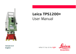
ScanStation C10/C5
User Manual
Version 5.0
English
2
ScanStation C10/C5, Introduction
Introduction
Purchase
Congratulations on the purchase of a ScanStation C10/C5 instrument.
This manual contains important safety directions as well as instructions for setting
up the product and operating it. Refer to "6 Safety Directions" for further information.
Read carefully through the User Manual before you switch on the product.
Product
identification
The type and the serial number of your product are indicated on the type plate.
Enter the model and serial number in your manual and always refer to this information when you need to contact your agency or Leica Geosystems authorised service
workshop.
Type:
_______________
Serial No.:
_______________
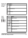
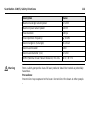
Symbols
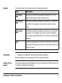
The symbols used in this manual have the following meanings:
Type
Warning
Danger
Caution
Description
Indicates an imminently hazardous situation which, if not
avoided, will result in death or serious injury.
Indicates a potentially hazardous situation or an unintended
use which, if not avoided, could result in death or serious
injury.
Indicates a potentially hazardous situation or an unintended
use which, if not avoided, may result in minor or moderate
injury and/or appreciable material, financial and environmental
damage.
Important paragraphs which must be adhered to in practice as
they enable the product to be used in a technically correct and
efficient manner.
Trademarks
• Windows is a registered trademark of Microsoft Corporation
All other trademarks are the property of their respective owners.
Validity of this
manual
This manual applies to the ScanStation C10 and C5 instruments. Differences for the
C5 model are marked and described.
ScanStation C10/C5, Introduction
3
ScanStation C10/C5, Table of Contents
4
Table of Contents
In this manual
Chapter
1
Description of the System
1.1
1.2
1.3
1.4
1.5
1.6
1.7
1.8
1.9
2
Page
Packing / Unpacking
Container Contents
Instrument Components
Power Supply
Other Components
Cabling
Field of View (FoV)
Description of the User Interface
HDS Cyclone Software Suite
8
8
9
11
13
19
20
26
27
39
Setting Up the Instrument
42
2.1
2.2
2.3
2.4
2.5
42
43
45
48
50
General Information
Scanner Setup on Tripod
Setup Over a Benchmark with the Internal Laser Plummet
Instrument Height
Power Supply and Charging
3
Scanning
62
3.1
3.2
3.3
62
63
65
68
69
71
74
76
78
3.4
Switching the System On/Off
Ambient Conditions
Onboard Controls
3.3.1
Scan
3.3.2
Manage
3.3.3
Status
3.3.4
Configuration
3.3.5
Tools
Cyclone SCAN
4
Troubleshooting
80
5
Care and Transport
86
5.1
5.2
5.3
5.4
5.5
5.6
5.7
5.8
86
87
88
89
90
92
94
95
Check & Adjust
Transport
Storage
Cleaning and Drying
Glass Cleaning Procedure
Adjustment of the Circular Level
Service of the Tripod
Adjustment of the Laser Plummet
ScanStation C10/C5, Table of Contents
5
ScanStation C10/C5, Table of Contents
6
Safety Directions
6.1
6.2
6.3
6.4
6.5
6.7
6.8
7
General
Intended Use
Limits of Use
Responsibilities
Hazards of Use
6.6.1
General
6.6.2
Distance Laser
6.6.3
Laser Plummet
Electromagnetic Compatibility EMC
FCC Statement, Applicable in U.S.
6
98
98
99
101
102
103
110
111
116
119
122
Technical Data
128
7.1
7.2
7.3
7.4
128
129
130
133
135
136
137
142
7.6
7.7
General Technical Data of the Instrument
System Performance
Laser Scanning System
Electrical
7.5.1
Scanner
7.5.2
GEB271 / GKL271 / GEB241
Physical
Accessories
8
International Limited Warranty, Software License Agreement
144
9
Microsoft End User License Agreement ("EULA")
146
Index
ScanStation C10/C5, Table of Contents
150
7
8
ScanStation C10/C5, Description of the System
1
Description of the System
1.1
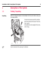
Packing / Unpacking
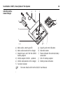
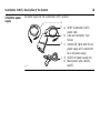
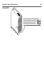
Unpacking
When in its transport container, the ScanStation C10/C5 can sit in either a face-up or
face-down position.
To take the instrument out of its container,
grasp the handle and the base of the instrument, and lift.
Use caution due to the weight of the instrument (13 kg).
C10_001
Pack the instrument the same way it is delivered.
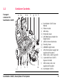
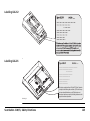
1.2
Container Contents
Transport
container for
ScanStation C10/C5
a bc
i
C10_002
j
d e
k
l
ScanStation C10/C5, Description of the System
f
g
h
f
m
a) ScanStation C10/C5 User
Manual
b) Ethernet cable
c) Allen keys
d) Protection cover
e) GHT196 distance holder for
height meter
f) GEB241 internal batteries
g) Cleaning tissue
h) GHM008 height meter
i) GEV230 AC power supply (not
supplied with system)
j) Power cable, country specific
k) Cyclone DVD and C10/C5
System CD-ROM
l) USB memory stick, not
supplied with system
m) ScanStation C10/C5
9
10
ScanStation C10/C5, Description of the System
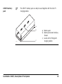
Transport
container for
ScanStation C10/C5
accessories
a
c
C10_003
d
e
f
b
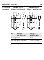
a) GEB271 external battery pack
b) GKL271 charging station
c) GEV225 AC power supply for
GKL271 charging station
d) GKL212 basic charger
including car adapter cable
e) GEB241 internal batteries
f) AC/DC adapter for basic
charger with daisy chain cable
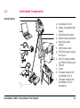
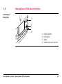
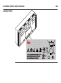
1.3
Instrument Components
Overall system
a
b
c
d
e
f
g
h
C10_004
ScanStation C10/C5, Description of the System
a) ScanStation C10/C5
b) Laptop, not supplied with
system
i
c) GEV228 ethernet cable
j d) GEB241 internal batteries
e) GEV230 AC power
adapter
f) GEV97 power cable
g) GEV225 AC power supply
for GKL271
k h) GKL271 charging station
and GEB271 battery pack
i) Tribrach
j) Tripod
k) Transport container for
ScanStation C10/C5
l l) Transport container for
ScanStation C10/C5
accessories
11
12
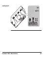
ScanStation C10/C5, Description of the System
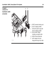
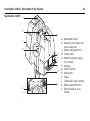
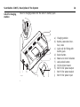
ScanStation C10/C5
a
b
f
c
d
g
h
i
j
k
l
e
C10_005
a) Removable handle
b) Rotating mirror (laser and
camera aperture)
c) Battery compartment B
d) Circular level
e) Socket for power supply,
5 pin female
f) Antenna
g) ON/OFF button
h) USB socket
i) Stylus
j) Touchscreen user interface
k) Battery compartment A
l) Ethernet socket, 8 pin
female
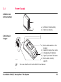
1.4
Power Supply
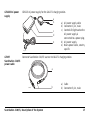
GEB241 Li-Ion
internal battery
a
C10_006
GKL212 basic
charger
a) GEB241 internal battery
b) Electrical contacts
b
a
b
c a) Mains cable socket on the
charger
b) Socket for daisy chain cable
d c) Charging bay for battery
d) Capacity and error indicators
e) Mains cable, country
e
specific
C10_007
For more details refer to the GKL212 User Manual.
ScanStation C10/C5, Description of the System
13
14
ScanStation C10/C5, Description of the System
GKL221 professional charger
a
b
c
j
d
k
e
f
C10_008
a) Mains cable, country specific
b) Mains cable socket on the charger
c) Adapter bays I and II for the GDI221
battery adapter
d) Vehicle adapter GDC221 - optional
e) Vehicle cable socket on the charger
f) Function indicator
g h
i
g) Capacity and error indicators
h) Selection button
i) Status indicator for external battery
connection
j) GDI 221 battery adapter
k) Battery status indicators
For more details refer to the GKL221 User Manual.
GEB271 battery
pack
The GEB271 battery pack can only be used together with the GKL271
charging station.
a
b
C10_009
ScanStation C10/C5, Description of the System
c
a) Battery pack
b) Battery connector interface,
female
c) Guide rail for fitting with
charging station
15
16
ScanStation C10/C5, Description of the System
GKL271 charging
station
GKL271 charging station for the GEB271 battery pack.
a
b
c
d
e
f
g
j
i
C10_010
h
a) Charging station
b) Battery connector interface, male
c) Guide rail for fitting with
battery pack
d) Select button
e) Power and error indicators
f) Lock/unlock button
g) Clip for tripod mount
h) Port P2 for power output
i) Port P1 for power output
j) Port P3 for power input
GEV225 AC power
supply
GEV225 AC power supply for the GKL271 charging station.
a
b
c
d
e
C10_011
GEV97
ScanStation C10/C5
power cable
a) AC power supply cable
b) Connector 3 pin, male
c) Control LED; lights when the
AC power supply is
connected to a power plug.
d) AC power supply
e) Mains power cable, country
specific
Connects ScanStation C10/C5 scanner to GKL271 charging station.
a
GEV97
ScanStation C10/C5, Description of the System
b
a) Cable
b) Connector 5 pin, male
17
18
ScanStation C10/C5, Description of the System
GEV230 AC power
supply
AC power supply for the ScanStation C10/C5 scanner.
a
b
c
d
e
C10_012
a) GEV97 ScanStation C10/C5
power cable
b) Cable and connector, 5 pin
female
c) Control LED; lights when the AC
power supply unit is connected
to an AC power supply.
d) GEV230 AC power supply unit
e) Mains power cable, country
specific
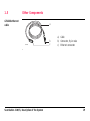
1.5
Other Components
GEV228 ethernet
cable
a
GEV228
ScanStation C10/C5, Description of the System
b
c
a) Cable
b) Connector, 8 pin male
c) Ethernet connector
19
20
ScanStation C10/C5, Description of the System
1.6
Cabling for
ScanStation C10/C5
with GEB271
battery pack
Cabling
a
b
c
d
C10_013
a)
b)
c)
d)
ScanStation C10/C5
GEV97 power cable
GEB271 battery pack
GKL271 charging station
Cabling for GEB271
battery pack with
GKL271 charging
station
a b
C10_014
•
•
c
d
a) GEV225 AC power supply
b) Mains power cable, country
specific
c) GEB271 battery pack
d) GKL271 charging station
The GEV225 AC power supply cannot be used as an AC power supply for the
scanner. It is designed exclusively for powering the charging station and must not
be connected to the instrument.
The GEB271 battery pack can only be used together with the GKL271 charging
station.
ScanStation C10/C5, Description of the System
21
ScanStation C10/C5, Description of the System
Danger
Danger
Warning
22
For GEV225 AC power supply:
The product is not designed for use under wet and severe conditions. If unit becomes
wet it may cause you to receive an electric shock.
Precautions:
Use the product only in dry environments, for example in buildings or vehicles.
Protect the product against humidity. If the product becomes humid, it must not be
used!
Death or serious injury can occur if unit is not connected to ground.
Precautions:
To avoid electric shock power cable and power outlet must be grounded.
Batteries not recommended by Leica Geosystems may be damaged if charged or
discharged. They may burn and explode.
Precautions:
Only charge and discharge batteries recommended by Leica Geosystems.
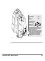
Cabling for
ScanStation C10/C5
with GEV230 AC
power supply
a
b
c
C10_015
d
a) GEV97 power cable
b) GEV230 AC power supply
c) Mains power cable, country
specific
d) GEV228 ethernet cable
The GEV230 AC power supply cannot be used as an AC power supply for the battery
charging station. It is designed exclusively for powering the scanner and must not be
connected to any other device.
ScanStation C10/C5, Description of the System
23
ScanStation C10/C5, Description of the System
Danger
Danger
24
For GEV230 AC power supply:
The product is not designed for use under wet and severe conditions. If unit becomes
wet it may cause you to receive an electric shock.
Precautions:
Use the product only in dry environments, for example in buildings or vehicles.
Protect the product against humidity. If the product becomes humid, it must not be
used!
Death or serious injury can occur if unit is not connected to ground.
Precautions:
To avoid electric shock power cable and power outlet must be grounded.
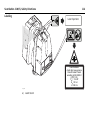
Laptop
A dedicated laptop computer is an option with your ScanStation C10/C5 system. This
computer must be loaded with proprietary software from Leica Geosystems, and
configured to operate with your instrument.
It is recommended that you do not use your dedicated laptop computer for any
purpose other than scanning with your instrument or other Leica HDS software
applications.
Using software, ethernet cards or modems that are not specifically designed to work
with your dedicated laptop computer can corrupt the settings in your computer, and
can adversely affect system performance.
ScanStation C10/C5, Description of the System
25
26
ScanStation C10/C5, Description of the System
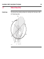
1.7
Field of View (FoV)
Field of view
The instrument has a rotating scanhead and a rotating mirror that covers a 360° x
270° field of view (FoV).
90°
0°
360°
45°
0°
45°
C10_016
360°
1.8
Description of the User Interface
Overview of
face plate
a
b
c
d
C10_017
ScanStation C10/C5, Description of the System
a)
b)
c)
d)
ON/OFF button
USB socket
Stylus
Touchscreen user interface
27
28
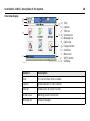
ScanStation C10/C5, Description of the System
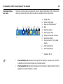
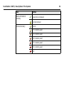
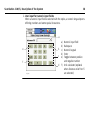
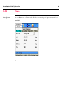
Overview display
a
b
c
f
g a)
b)
c)
h d)
e)
f)
i g)
h)
i)
j
j)
k k)
d
e
C10_035
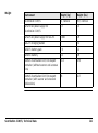
Element
Description
Time
The current local time is shown.
Caption
Shows location in menu system.
Title bar
Shows name of current screen.
Screen area
Working area of the screen.
Message bar
Shows messages.
Time
Caption
Title bar
Screen area
Message bar
Status bar
Escape button
Scroll bar
Menu icon
SHIFT button
Softkeys
Element
Description
Status bar
Shows current status information for the instrument.
Escape button
Returns to the previous screen.
Scroll bar
Scrolls the screen up and down.
Menu icon
Selecting menu icons opens submenus. Menu icons will change
depending on which menu is displayed.
SHIFT button
Displays the second level of softkeys.
Softkeys
Commands can be executed with the softkeys. Commands
assigned to the softkeys are menu dependent.
ScanStation C10/C5, Description of the System
29
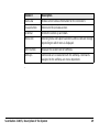
30
ScanStation C10/C5, Description of the System
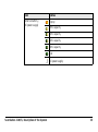
Overview status
bar icons
The icons in the status bar display the current status information of the instrument.
Clicking a status icon gives direct access to a detailed status description.
a
C10_036
b
c
d e f
g h i
j k
a)
b)
c)
d)
e)
f)
g)
h)
i)
Range Filter
Active target type
Dual-axis compensator*
WiFi
External camera
Internal hard disc
Status of external memory
External memory
External battery / AC power
supply
j) Internal battery A
k) Internal battery B
*
•
•
Optional for C5
Internal battery A indicates the status of the battery in compartment A which
is located at the same side cover as the touchscreen.
Internal battery B indicates the status of the battery in compartment B at the
opposite side cover without a screen.
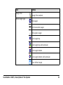
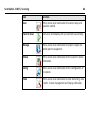
Icon
Range Filter
Active target type
Status
Range Filter enabled
HDS target
HDS black/white target
HDS sphere target
Twin target top
Twin target top with extension
Twin target bottom
Twin target bottom with extension
User defined target
ScanStation C10/C5, Description of the System
31
32
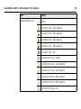
ScanStation C10/C5, Description of the System
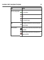
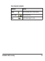
Icon
Dual-axis compensator
Status
On and levelled
Off
On but out of range
WiFi
WiFi adapter connected to scanner and ready for
communication.
External camera
External camera connected and selected for image
acquisition.
External camera connected but not selected for
image acquisition.
Icon
Internal hard disc
Status
Empty
13% memory used
25% memory used
38% memory used
50% memory used
63% memory used
75% memory used
88% memory used
Full
ScanStation C10/C5, Description of the System
33
34
ScanStation C10/C5, Description of the System
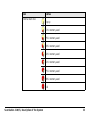
Icon
Status
Status of external
memory
Ready to be removed.
External memory
Empty
Do not remove!
17% memory used
33% memory used
50% memory used
67% memory used
83% memory used
Full
Icon
Status
External battery /
AC power supply
Empty
20% capacity
40% capacity
60% capacity
80% capacity
Full
AC power supply
ScanStation C10/C5, Description of the System
35
36
ScanStation C10/C5, Description of the System
Icon
Status
Internal battery A/B
Empty
Currently in use - 20% capacity
Currently in use - 40% capacity
Currently in use - 60% capacity
Currently in use - 80% capacity
Currently in use - full
Currently not in use - empty
Currently not in use - 20% capacity
Currently not in use - 40% capacity
Currently not in use - 60% capacity
Currently not in use - 80% capacity
Currently not in use - full
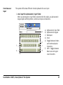
Overview user
input
The system offers two different virtual keyboards for user input:
1. User input for alphanumeric input fields:
When an alphanumeric input field is selected with the stylus, an alphanumeric
keypad opens offering letters, numbers and special characters.
a
b
f
c
e
d
C10_037
ScanStation C10/C5, Description of the System
a)
b)
c)
d)
e)
f)
Alphanumeric input field
Alphanumeric keypad
Backspace
Enter
Toggle between letters
and numbers/special
characters
Shift - Toggle between
lower case and upper
case characters
37
38
ScanStation C10/C5, Description of the System
2. User input for numeric input fields:
When a numeric input field is selected with the stylus, a numeric keypad opens
offering numbers and some special characters.
a
e
c
a)
b)
c)
d)
e)
d
f)
b
f
C10_038
Numeric input field
Backspace
Numeric keypad
Enter
Toggle between positive
and negative number
Unit calculator (optional
when distance units ft or fi
are selected)
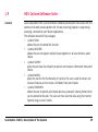
1.9
HDS Cyclone Software Suite
General
Leica Geosystems HDS Cyclone software modules provide point cloud users with the
widest set of work process options for 3D laser scanning projects in engineering,
surveying, construction and related applications.
The software consist of five packages:
• Cyclone SCAN:
allows the user to control the Scanner.
• Cyclone REGISTER:
allows the user to register multiple Scans together or to Geo-reference point
clouds.
• Cyclone SURVEY:
gives the user basic functionality to extract and measure information from point
clouds.
• Cyclone MODEL:
gives the user the full functionality of Cyclone. The user is able to extract and
measure features and to create a 3D Model from point clouds.
• Cyclone PUBLISHER:
allows the user to publish point cloud data to a panoramic viewing format which
can be posted to the web. The user can then view this data using the Internet
Explorer plug-in Leica TruView.
ScanStation C10/C5, Description of the System
39
ScanStation C10/C5, Description of the System
•
•
General operating
principles
•
40
For more information on Cyclone Software Suite, please visit:
http://www.leica-geosystems.com/hds
Cyclone Software has also online help available which can be accessed by
pressing the F1 key on your keyboard.
Download:
Cyclone software, as well as important support documentation, can be down-
•
loaded from the Leica Geosystems HDS Website
(http://www.leica-geosystems.com/hds/en/27054.htm).
The user must create an account before the download section is accessible.
Installation:
You must use a Windows account with administrator privileges to install or
upgrade Cyclone, CloudWorx for AutoCAD, CloudWorx for MicroStation,
CloudWorx for PDMS or CloudWorx for Intergraph SmartPlant® Review.
1.
2.
3.
4.
•
Download the Cyclone Installshield from the website shown above.
Run the Installation file.
Follow the onscreen instructions and select the software you wish to install.
Go to the License Request Page.
Language:
Cyclone's operating language is English.
ScanStation C10/C5, Description of the System
41
ScanStation C10/C5, Setting Up the Instrument
42
2
Setting Up the Instrument
2.1
General Information
Use the tripod
The instrument should always be set up on its tripod. Using the tripod specified for
the scanning system guarantees maximum stability during scanning operations.
Always set up the instrument on its tripod. Do not set up the instrument directly on
the ground for scanning operations.
It is always recommended to shield the instrument from direct sunlight and avoid
uneven temperatures around the instrument.
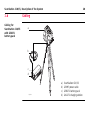
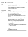
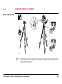
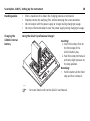
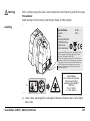
2.2
Scanner Setup on Tripod
Setup step-by-step
5
2
6
6
2
3
3
1
1
4
4
3
1
4
C10_018
Shield the instrument from direct sunlight and avoid uneven temperatures
around the instrument.
ScanStation C10/C5, Setting Up the Instrument
43
ScanStation C10/C5, Setting Up the Instrument
44
1. Extend the tripod legs to allow for a comfortable working posture. Tighten the
screws at the bottom of the legs.
2. Place the tribrach on the tripod and secure it with the central fixing screw.
3. Set up the tripod so that the tripod plate is as horizontal as possible.
4. Push the tripod legs firmly into the ground.
5. Place the instrument on the tribrach and secure it with the tribrach’s locking
knob.
6. Level up the instrument using the instrument’s circular level. Turn two of the foot
screws together in opposite directions. The index finger of your right hand indicates the direction in which the bubble should move. Now use the third foot
screw to centre the bubble.
The instrument must be levelled before it is switched ON. If not levelled
using the tribrach’s or the instrument’s circular level, it may not power up
properly or scanning accuracy may not be achieved.
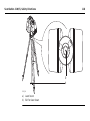
2.3
Setup Over a Benchmark with the Internal Laser Plummet
Description
This topic describes an instrument setup over a marked ground point using the laser
plummet. Geo-referencing of the ScanStation C10/C5 is established by setting up
over a known or assumed control point, with optional reference target measurement
to set the azimuth direction, and establishing a local or global coordinate system.
The ScanStation C10/C5 allows you to traverse, resect or free-station. Known
azimuth or known backsight measurements can be observed.
It is always possible to set up the instrument without the need for a marked ground
point.
The data scanned with ScanStation C10/C5 is corrected by an internal dual-axis
compensator*, when the dual-axis compensator is enabled (via onboard control or
Cyclone).
*
Optional for C5
•
The laser plummet described in this topic is built into the vertical axis of the
instrument. It projects a red spot onto the ground, making it much easier to
centre the instrument.
The laser plummet cannot be used in conjunction with a tribrach equipped with
an optical plummet.
•
ScanStation C10/C5, Setting Up the Instrument
45
46
ScanStation C10/C5, Setting Up the Instrument
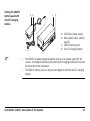
Setup step-by-step
e
f
g
c
k
d
h
a
a
j
a
b
j
j
i
C10_019
Shield the instrument from direct sunlight and avoid uneven temperatures
around the instrument.
1. Extend the tripod legs to allow for a comfortable working posture (a). Position
the tripod approximately over the marked ground point, centring it as well as
possible (b).
2. Place the tribrach on the tripod (c) and secure it with the central fixing screw (d).
3. Place the instrument on the tribrach (e) and secure it with the tribrach’s locking
knob.
4. Turn on the instrument by pressing the ON/OFF button (f). Go to Status, Level
and Laser Plummet, Plummet and activate the laser plummet (g).
5. Move the tripod legs (a) and use the tribrach footscrews (h) to centre the
plummet (i) over the ground point.
6. Adjust the tripod legs (j) to level the circular level (k).
7. By using the electronic level (Status, Level and Laser plummet, Level) turn the
tribrach footscrews (h) to precisely level the instrument.
8. Centre the instrument precisely over the ground point (i) by shifting the tribrach
on the tripod plate.
9. Repeat steps 7. and 8. until the required accuracy is achieved.
Please see also section "Scanning with ScanStation C10/C5" in the Cyclone
documentation for more information.
ScanStation C10/C5, Setting Up the Instrument
47
48
ScanStation C10/C5, Setting Up the Instrument
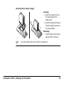
2.4
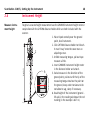
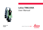
Instrument Height
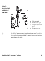
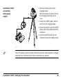
Measure instrument height
To get an accurate height measurement use the GHM008 instrument height meter in
conjunction with the GHT196 distance holder which are both included with the
scanner.
1.627
2
C10_040
6
5
1. Place tripod centrally over the ground
point, level instrument.
2. Click GHT196 distance holder to tribrach.
It must "snap" onto the cover over an
adjusting screw.
3. Unfold measuring tongue, pull out tape
measure a little.
4. Insert GHM008 instrument height meter
in the distance holder and attach.
5. Swivel measure in the direction of the
ground point, pull out until the tip of the
measuring tongue touches the point on
the ground, keep under tension and do
not allow to sag, clamp if necessary.
6. Read height of the instrument (ground tilt axis) in the reading window at the red
marking (in the example 1.627 m).
•
•
•
For detailed information about the GHM008 instrument height meter
and GHT196 distance holder refer to the GHM008/GHT196 user manual
which is delivered with these items.
The tilt axis height of the ScanStation C10/C5 is 250 mm. Take care to
use the GHM008 which has a special scale to measure the height of
instruments with a tilt axis height of 250 mm. Do not use a tape with
any other scale.
Alternatively the instrument height can be measured with a common,
1:1 scaled measuring tape from the point on the ground to the little
notch under the red Leica logo at both side covers of the scanner. This
distance will then be from the ground point to the tilt axis.
ScanStation C10/C5, Setting Up the Instrument
49
ScanStation C10/C5, Setting Up the Instrument
2.5
50
Power Supply and Charging
Primary use/charging
• The battery must be charged prior to using for the first time because it is delivered with an energy content as low as possible.
• The permissible temperature range for charging is between 0°C to +45°C / +32°F
to +113°F. For optimal charging we recommend charging the battery at a low
ambient temperature of +10°C to +20°C / +50°F to +68°F if possible.
• It is normal for the battery to become warm during charging. Using the chargers
recommended by Leica Geosystems, it is not possible to charge the battery if the
temperature is too high or too low.
• For new batteries or batteries that have been stored for a long time (> three
months), it is effectual to make only one charge/discharge cycle.
• For Li-Ion batteries, a single discharging and charging cycle is sufficient. We
recommend carrying out the process when the battery capacity indicated on the
charger or on a Leica Geosystems product deviates significantly from the actual
battery capacity available.
Operation/Discharging
• The battery can be operated from -20°C to +55°C / -4°F to +131°F.
• Low operating temperatures reduce the capacity that can be drawn; very high
operating temperatures reduce the service life of the battery.
As the battery pack contains rechargeable cells it is always recommended to handle
the battery and charging station with care. Observe the LEDs on the charging station
before and after the charging process, as well as during operation. For details please
refer to section "Indicator panel" on page 52.
•
•
When port P3 is connected for charging, both ports P1 and P2 cannot be used
for operation: no simultaneous charging and discharging.
When port P1 is connected for operation, port P2 cannot be used for operation
and vice versa: no simultaneous operation of two ports.
ScanStation C10/C5, Setting Up the Instrument
51
52
ScanStation C10/C5, Setting Up the Instrument
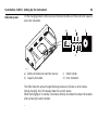
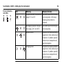
Indicator panel
On the charging station’s front side are the Select button and three LEDs for capacity
and error indication.
a
b
a
a
c
d
C10_020
a) Safety directions to read this manual
b) Capacity indication
c) Select button
d) Error indication
The LEDs show the actual charge/discharge status or indicate an error status.
During charging, the LEDs always show the current status.
While discharging or in standby, the status will only be shown for about 10 seconds
after pressing the select button.
Explanation of the
symbols used in
this chapter
Symbol
Meaning
LED off.
LED permanently on.
LED flashing.
Capacity
indicators,
green LEDs
LED
Meaning
Battery fully charged
Battery capacity minimum 80%
Battery capacity minimum 50%
Battery capacity minimum 10%
Battery capacity <10%
ScanStation C10/C5, Setting Up the Instrument
53
54
ScanStation C10/C5, Setting Up the Instrument
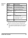
Error indicators,
red LEDs
LED
Meaning
Measure to take
Charging outside temperature Use within specified temperarange 0°C to 45°C
ture range only. LED keeps
flashing until problem is
resolved.
Discharging outside temperature range -20°C to +55°C
Use within specified temperature range only.
Battery defect
Disconnect all cables and other
equipment, check contacts and
reconnect. If problem persists,
contact Leica Geosystems or
your local agency.
Charging error
Disconnect all cables and other
equipment, check contacts and
reconnect. If problem persists,
contact Leica Geosystems or
your local agency.
Additional status
indicators
•
•
When the GEB271 battery pack is inserted into the GKL271 charging station, the
three LEDs light green for one second.
When the GEV225 AC adapter is connected to the GKL271 charging station for
charging, the three LEDs light green for one second and then show the actual
battery level.
If the charger indicates an error when the battery is connected, try connecting a
different battery to find out whether the fault lies with the battery or with the
charging station.
If the problem persists, contact Leica Geosystems or your local agency.
ScanStation C10/C5, Setting Up the Instrument
55
56
ScanStation C10/C5, Setting Up the Instrument
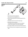
Charging the
battery
2
1
4
3
C10_021
1. Slide the battery pack into the charging station.
When connected, the three LEDs light up for 1 sec.
2. Plug the AC power supply cable of the AC power supply into port P3 of the
charging station.
3. Plug the power cable into the AC port of the AC power supply.
4. Plug the power cable into a socket outlet.
The charging process starts automatically when all parts are plugged in.
The battery is fully charged when all three LEDs are flashing green.
5. After charging is completed, remove the power cable from the socket outlet.
6. Remove the battery pack from the charging station by moving the lock/unlock
button.
Danger
Period of use, life
span of the power
supply
For AC power supply:
The product is not designed for use under wet and severe conditions. If unit becomes
wet it may cause you to receive an electric shock.
Precautions:
Use the product only in dry environments, for example in buildings or vehicles.
Protect the product against humidity. If the product becomes humid, it must not be
used!
Operation time for a fully charged external power supply is approximately six hours
at room temperature.
Before storing the power supply for a long period of time, recharge it to
avoid shortening the life span.
Before storage, remove the battery from the charging station.
ScanStation C10/C5, Setting Up the Instrument
57
58
ScanStation C10/C5, Setting Up the Instrument
Handling advice
•
•
•
•
Charging the
GEB241 internal
battery
Using the GKL221 professional charger:
After a maximum of six hours the charging process is terminated.
Properly remove the wall plug first, before removing the Lemo connector.
Do not tamper with the power supply or charger during charging or usage.
Do not put flammable objects near the power supply during charging or usage.
2
1
Inserting:
1. Insert the battery flush to
the front edge of the
GDI221 battery bay.
2. Push the battery to the back
with only slight pressure to
the stop position.
Removing:
• Pull the battery to the front
stop and then remove it.
C10_022
For more details refer to the GKL221 User Manual.
Using the GKL212 basic charger:
1
C10_023
2
Inserting:
1. Insert the battery flush to
the front edge of the
battery bay.
2. Push the battery to the back
with only slight pressure to
the stop position.
Removing:
• Pull the battery to the front
stop and then remove it.
For more details refer to the GKL212 User Manual.
ScanStation C10/C5, Setting Up the Instrument
59
60
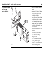
ScanStation C10/C5, Setting Up the Instrument
ScanStation C10/C5
and internal
battery GEB241
1
3
5
4
2
C10_024
1. Open the battery compartment.
2. Remove the battery holder.
3. Remove the battery from
the battery holder.
Insert the new battery into
the battery holder, ensuring
that the contacts are facing
outward and that the tip on
the holder fits into the slot
of the battery.
The battery should click into
position.
4. Insert the battery holder
back into the battery
compartment.
5. Turn the knob to lock the
battery holder in place.
6. Switch on the instrument to
start the boot process.
ScanStation C10/C5
and external
battery pack
GEB271
3
2
1
1. Slide the battery pack into the
charging station.
When connected, the three LEDs on
the charging station light up for
1 sec.
2. Connect the GEV97 power cable to
port P1 of the charging station.
3. Connect the other end of the GEV97
power cable to the power port of the
instrument.
4. Press the ON/OFF button on the
instrument to start the boot process.
C10_025
Check the battery capacity indicator LEDs to ensure that remaining power is enough
to operate the instrument and finish the scheduled scan process.
ScanStation C10/C5, Setting Up the Instrument
61
62
ScanStation C10/C5, Scanning
3
Scanning
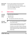
3.1
Switching the System On/Off
Switch on
procedure
1. Set up the instrument as desired. Refer to chapter "2 Setting Up the Instrument"
for more information.
2. Press and hold the ON/OFF button until a beep is audible.
3. The instrument’s fan starts.
4. The Leica Geosystems welcome screen starts.
5. Wait until the Main Menu appears on the display and the Idle State message is
shown in the message bar.
6. Once in Idle State the scanner is ready for operation.
Switch off
procedure
1. From the current menu return to the Main Menu.
2. In the Main Menu press the
button.
3. In the popup window confirm the question Do you really want to power down
the scanner? with Yes.
4. Wait for the scanner to shut down.
Alternative switch
off procedure
In the event of a system crash follow the alternative switch off procedure:
1. Press and hold the ON/OFF button for a minimum of 6 seconds.
2. After 3 seconds a single beep and after 6 seconds a double beep is audible.
3. After the double beep release the ON/OFF button.
4. Wait for the scanner to shut down.
3.2
Ambient Conditions
Unfavourable
surfaces for
scanning
•
•
•
Unfavourable
weather conditions
Highly reflective (polished metal, gloss paint)
Highly absorbent (black)
Translucent (clear glass)
Color or powder these surfaces before scanning if necessary.
•
•
•
ScanStation C10/C5, Scanning
Rain, snow or fog cause poor measurements, so it is not possible to
survey during these conditions!
Surfaces that are directly illuminated by the sun cause an increased
range noise and therefore a larger measurement uncertainty.
If some objects are scanned against the sunlight or a bright spotlight,
the optical receiver of the instrument can be dazzled so heavily that in
this area no measured data is recorded. A "black hole" appears in the
reflectance image.
63
ScanStation C10/C5, Scanning
Temperature
changes
Dirt on the glass
pane
64
If the instrument is brought from a cold environment, for example from
storage, into a warm and humid environment, the glass window at the
mirror or in extreme cases even the interior optics can condensate. This
may cause measurement errors.
Precaution: Avoid rapid temperature changes and give the instrument time
to acclimatise.
Dirt on the glass pane of the mirror such as a layer of dust, condensation
or fingerprints may cause considerable measuring errors.
3.3
Onboard Controls
Description
The Main Menu will be displayed after the system boot process. Idle State in the
message bar indicates that the instrument is ready for scanning.
For a complete description of all menus and commands refer to the Leica
ScanStation C10/C5 System Field Manual.
ScanStation C10/C5, Scanning
65
66
ScanStation C10/C5, Scanning
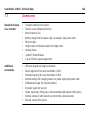
Icon
Function
Scan
Offers access to all commands for scanner setup and
operation control.
Favorite Scan
Starts scan immediately with pre-defined scan settings.
Manage
Offers access to all commands for project, target and
control point management.
Status
Offers access to all commands for the scanner’s status
information.
Config
Offers access to all commands for the configuration of
the system.
Tools
Offers access to all commands for disk formatting, data
transfer, license management and display calibration.
Menu independent commands:
Command
Function
Escape
Return to previous menu in menu hierarchy.
Shift -> Quit
Return to main menu.
Page
Switch between pages in a menu.
ScanStation C10/C5, Scanning
67
ScanStation C10/C5, Scanning
3.3.1
Scan
Description
In the Scan menu all commands for the scanner setup and operation control are
available.
68
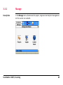
3.3.2
Manage
Description
In the Manage menu all commands for project, target and control point management
on the scanner are available.
ScanStation C10/C5, Scanning
69
70
ScanStation C10/C5, Scanning
Icon
Function
Projects
Offers access to all commands for project management.
Targets
Offers access to all commands for target management.
Control
Points
Offers access to all commands for control points management.
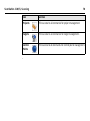
3.3.3
Status
Description
In the Status menu all commands for the scanner’s status information are available.
ScanStation C10/C5, Scanning
71
72
ScanStation C10/C5, Scanning
Icon
Command
Description
Battery &
Memory
Battery
Status information about internal
battery, external battery and AC
power supply.
Memory
Status information about size and
free space of internal hard disk’s
data partition.
Instrument
Status information about instrument
type, serial number, equipment
number and system language.
Firmware
Status information about installed
firmware version and firmware
maintenance expiry date.
Options
Status information about installed
external camera option and installed
set of options on a C5.
System
Information
Icon
Command
Description
Level & Ls
Plummet
Level
Numerical and graphical display of
instrument's tilt.
Plummet
Switch laser plummet on/off.
Compens
Switch dual-axis compensator*
on/off. Define how scanner should
react when compensator goes out
of range.
WiFi
Define region code and TX power
for external WiFi communication
device. The WiFi device should be
connected to the scanner before
this function is selected.
WiFi
*
Optional for C5
ScanStation C10/C5, Scanning
73
ScanStation C10/C5, Scanning
74
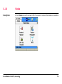
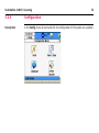
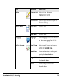
3.3.4
Configuration
Description
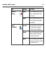
In the Config menu all commands for the configuration of the system are available.
Icon
Command
Description
Units
Distance Unit
Select unit for distances
(Metre, Int Ft, Us Ft).
Distance Dec
Select number of decimal digits for
distance display.
Local Time
Set local time.
Time & Date
Local Date
Set local date.
Language
Language
Select language for the user interface
or delete a language from the list.
Define Favorite
Fld of View
Select area of interest and scanner
action for Favorite Scan.
Resolution
Define horizontal and vertical point
spacing for Favorite Scan.
Image Ctrl
Define parameters of internal camera
for Favorite Scan.
Filters
Define filter parameters for
Favorite Scan.
ScanStation C10/C5, Scanning
75
ScanStation C10/C5, Scanning
76
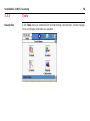
3.3.5
Tools
Description
In the Tools menu all commands for disk formatting, data transfer, license management and display calibration are available.
Icon
Command
Format
Description
Format the complete data partition
of the internal hard disk.
All project data will be
erased.
Transfer
License
Display
Calibration
ScanStation C10/C5, Scanning
Projects
Transfer selected project or all
projects to USB memory storage
device.
System Files
Upload new firmware or language
file to the instrument.
Manual
Enter license key manually.
Upload
Upload license key file from USB
memory storage device.
Recalibrate the touch screen by
clicking three points on the display.
77
ScanStation C10/C5, Scanning
78
3.4
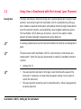
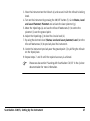
Cyclone SCAN
Scanning with
Cyclone SCAN
In addition to the onboard control the ScanStation C10/C5 can be controlled via the
Cyclone SCAN interface.
1. Connect one end of the ethernet cable to the ScanStation C10/C5 ethernet
connector and the other end to a computer which has Cyclone SCAN installed.
2. Start Cyclone SCAN.
3. In the Cyclone Navigator select Configure, Scanners.
4. In the Configure Scanners window press the Add button.
5. In the Add Scanner window select ScanStation C10/C5 for the scanner model
and add a descriptive scanner name (for example “ScanStation C10/C5 (xxxx)”
with xxxx being the scanner’s serial number). No IP address is needed for the
ScanStation C10/C5.
Close the Add Scanner window to return to the Cyclone Navigator.
6. In the Cyclone Navigator expand the Scanners folder and double click the new
scanner name to open the Scan Control window.
7. The initial Scan Control window prompts to select a project folder in the Select
Project window.
8. In the Select Project window select an existing project folder or create a new
one. Close this window by confirming with the OK button.
9. In the Scan Control window select Scanner, Connect to connect your computer
to the scanner. After connection has been established the Scan Control window
will show the status Connected and ready at the bottom of the window.
ScanStation C10/C5 and Cyclone are now ready to start a scan.
•
•
•
•
Retain enough free disk space on the computer: depending on your project, up
to 50% of your hard disk.
Do not additionally overload the computer with additional tasks and applications
while scanning.
It is not recommended to perform other Cyclone tasks while scanning.
For details about the ScanStation C10/C5 scan operation with Cyclone SCAN refer
to the Cyclone help system or your local support team.
ScanStation C10/C5, Scanning
79
80
ScanStation C10/C5, Troubleshooting
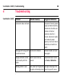
4
ScanStation C10/C5
Troubleshooting
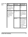
Problem
Possible Cause(s)
Suggested Remedies
Instrument does not boot.
Disconnect from AC power
supply or external battery.
Disconnect all cables and
remove all internal
batteries. Wait for 1
minute. Reconnect cables
and external power
sources, insert all internal
batteries and switch on
again.
Black gap of missing points Handle not removed.
in overhead scans.
Remove handle and scan
area again.
Display elements cannot
be hit exactly with the
stylus.
Touch screen not calibrated.
Recalibrate touch screen
via Tools, Calibration.
Missing points in scan.
Dust, debris or fingerprints Use glass cleaning kit to
on optics of rotating mirror. clean the specific areas.
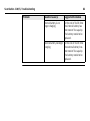
ScanStation C10/C5
Battery
Problem
Possible Cause(s)
When switching on the
instrument or starting a
scan, the system switches
off automatically.
Capacity of battery is too Recharge or change
low.
battery.
When switching on the
instrument or starting a
scan, the system switches
off automatically even
though it was totally
recharged.
Battery charger is defective.
Check the function of the
battery charger. Please
note the charging status
displayed on the battery
charger.
Damaged cable.
Examine the cabling and
pay attention to damages,
which for example can
cause loose contacts or
shirt circuits. Defective
circuits need to be
replaced. Only use supplied
power cables.
ScanStation C10/C5, Troubleshooting
Suggested Remedies
81
82
ScanStation C10/C5, Troubleshooting
Problem
Possible Cause(s)
Suggested Remedies
Internal battery is no
longer charging.
At the end of its life time
the internal battery has
lost most of its capacity.
The battery needs to be
replaced.
External battery no longer At the end of its life time
charging.
the external battery has
lost most of its capacity.
The battery needs to be
replaced.
Diagnostic
procedure
The diagnostic procedure explains how to create log files with the user interface of
your ScanStation C10/C5 instrument in case of problems with the scanner.
To create log files, follow the steps described below:
From the Main Menu go to Tools, Transfer, Transfer Project.
Connect an external USB memory device to the scanner’s USB connector.
Press the Logs button.
In the USB memory devices's main directory a folder named Logs will be created
containing log files:
• C10_1234.log: log file of current scan day with 1234 being the last four digits
of the scanner serial number,
• C10_1234.20100829.log: older log file with scanner serial number and scan
date embedded in the file name (year, month, day),
• UpgraderLog.txt,
• svclog.txt,
• XenaService.log.
5. Send the content of the Logs folder together with details about scanner type,
scanner serial number and a short description of the problem to your local
support team.
1.
2.
3.
4.
For a ScanStation C5 model the diagnostic files are named C5_1234.log and
C5_1234.20100829.log with 1234 being the last four digits of the scanner serial
number.
ScanStation C10/C5, Troubleshooting
83
ScanStation C10/C5, Troubleshooting
Summary
If you experience problems with your instrument:
• Email the scanner's log files to your local support:
• For Americas support: [email protected]
• For Europe, Middle East and Africa support:
[email protected]
• For Asia support: [email protected]
•
Log files are stored on the USB memory stick in the folder Logs.
84
ScanStation C10/C5, Troubleshooting
85
ScanStation C10/C5, Care and Transport
5
Care and Transport
5.1
Check & Adjust
Caution
86
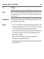
Units that are exposed to high mechanical forces, e.g. through frequent transport or
rough handling, it is recommended to carry out a check and adjust once a year by the
manufacturer respectively just after such a high stress exposure.
5.2
Transport
Transport
in the field
When transporting the equipment in the field, always make sure that you
• either carry the product in its original transport container,
• or carry the tripod with its legs splayed across your shoulder, keeping the
attached product upright,
• or remove product from tripod and carry it by its handle.
Transport
in a road vehicle
Never carry the product loose in a road vehicle, as it can be affected by shock and
vibration. Always carry the product in its transport container and secure it.
Shipping
When transporting the product by rail, air or sea, always use the complete original
Leica Geosystems packaging, transport container and cardboard box, or its equivalent, to protect against shock and vibration.
Shipping, transport
of batteries
When transporting or shipping batteries, the person in charge of the product must
ensure that the applicable national and international rules and regulations are
observed. Before transportation or shipping, contact your local passenger or freight
transport company.
ScanStation C10/C5, Care and Transport
87
ScanStation C10/C5, Care and Transport
88
5.3
Storage
Product
Respect the temperature limits when storing the equipment, particularly in summer
if the equipment is inside a vehicle. Refer to "7 Technical Data" for information about
temperature limits.
Field adjustment
After long periods of storage, inspect the field adjustment parameters given in this
user manual before using the product.
Batteries
•
•
•
•
•
•
Refer to "7.5 Environmental" for information about storage temperature range.
A storage temperature range of +5°C to +35C / +41°F to +95°F in a dry environment is recommended to minimize self-discharging of the battery.
At the recommended storage temperature range, batteries containing a 10% to
50% charge can be stored for up to one year. After this storage period the
batteries must be recharged.
Remove batteries from the product and the charger before storing.
After storage, recharge batteries before using.
Protect batteries from damp and wetness. Wet or damp batteries must be dried
before storing or use.
5.4
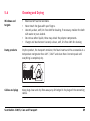
Cleaning and Drying
Windows and
targets
•
•
•
•
•
Blow dust off scanner windows.
Never touch the glass with your fingers.
Use only a clean, soft, lint-free cloth for cleaning. If necessary, moisten the cloth
with water or pure alcohol.
Do not use other liquids; these may attack the polymer components.
Charger and touchscreen: Use only a clean, soft, lint-free cloth for cleaning.
Damp products
Dry the product, the transport container, the foam inserts and the accessories at a
temperature not greater than 40°C / 104°F and clean them. Do not repack until
everything is completely dry.
Cables and plugs
Keep plugs clean and dry. Blow away any dirt lodged in the plugs of the connecting
cables.
ScanStation C10/C5, Care and Transport
89
ScanStation C10/C5, Care and Transport
90
5.5
Glass Cleaning Procedure
General
The ScanStation C10/C5 scanning mirror must be kept clean. The instructions must
be followed as described in this chapter to clean the scanner mirror.
Warning
Direct intrabeam viewing is always hazardous.
Precautions:
Before cleaning glass, ensure the instrument is switched off.
Dust and debris
removal
Using a compressed gas duster (e.g., UltraJet ®2000 Gas Duster or UltraJet®
Compressed CO2 Duster), remove dust and debris from surface of scanner glass.
Never rub off dust or debris as this will scratch the glass and so possibly cause permanent damage to the special optical coatings.
Cleaning of the
optics
Soiling of the glass pane can cause extreme measurement errors and therefore
useless data!
Caution
Precautions:
All soiling that is visible on the glass pane has to be removed, except for single small
dust particles that adhere inevitably.
Clean the glass pane regularly with the provided cleaning tissue:
• Switch off instrument.
• Washing hands is necessary in order to avoid grease on the cleaning
tissue.
• Better, use gloves to avoid finger oil on the glass.
• Then use the lens tissue for wiping circularly from the center to the edge
until there is only a thin film of detergent visible.
• If any smears from cleaning are visible against back light, repeat the
procedure.
• Do not use air from the pneumatic power system as this is always slightly
oily!
ScanStation C10/C5, Care and Transport
91
92
ScanStation C10/C5, Care and Transport
5.6
Adjustment of the Circular Level
On the instrument
step-by-step
C10_026
1. Level up the instrument in advance with the electronic level, assuming that the
instrument is correctly adjusted. In the Main Menu go to Status, Level and
Laser plummet, Level to access the electronic bubble.
2. The bubble must be centered. If it extends beyond the circle, use an allen key to
center it with the adjustment screws. Turn the instrument slowly 200 gon (180°).
Repeat the adjustment procedure if the bubble does not stay centered.
After the adjustment, no screw shall be loose.
On the tribrach
step-by-step
C10_027
1. Level up the instrument with the electronic level, assuming that the instrument
is correctly adjusted. Remove the instrument from the tribrach. In the Main
Menu go to Status, Level and Laser plummet, Level to access the electronic
bubble.
2. The bubble of the tribrach must be centered. If it extends beyond the circle, use
the adjusting pin in conjunction with the two cross-headed adjustment screws to
centre it.
After the adjustment, no screw shall be loose.
ScanStation C10/C5, Care and Transport
93
94
ScanStation C10/C5, Care and Transport
5.7
Service tripod
step-by-step
Service of the Tripod
1
2
3
C10_028
The connections between timber and metal must be firm and tight.
1. Moderately tighten the allen screws with the allen key supplied with the tripod.
2. Tighten articulated joints just enough to keep the tripod legs open when lifting
the tripod off the ground.
3. Tighten the allen screws of the tripod legs.
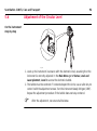
5.8
Inspecting the
laser plummet
step-by-step
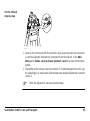
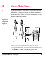
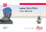
Adjustment of the Laser Plummet
The laser plummet is located in the vertical axis of the instrument. Under normal
conditions of use, the laser plummet does not need adjusting. If an adjustment is
necessary due to external influences, the instrument has to be returned to any Leica
Geosystems authorised service workshop.
5
1
2
3
360°
6
Ø 2.5 mm / 1.5 m
4
≤ 3 mm / 1.5 m
C10_039
1. Place and secure the instrument into the tribrach and onto a tripod.
2. Using the tribrach footscrews, level the instrument with the electronic level. In
the Main Menu go to Status, Level and Laser plummet, Level.
ScanStation C10/C5, Care and Transport
95
ScanStation C10/C5, Care and Transport
96
3. Press Page to access the Laser Plummet page. Switch on the laser plummet.
Inspection of the laser plummet should be carried out on a bright, smooth and
horizontal surface, like a sheet of paper.
4. Mark the centre of the red dot on the ground.
5. Turn the instrument through 360° slowly, carefully observing the movement of
the red laser dot.
The maximum diameter of the circular movement described by the centre
of the laser point should not exceed 3 mm at a distance of 1.5 m.
6. If the centre of the laser dot describes a perceptible circular movement or moves
more than 3 mm away from the point which was first marked, an adjustment may
be required. Inform your nearest Leica Geosystems authorised service workshop.
Depending on brightness and surface, the diameter of the laser dot can vary. At
1.5 m it is about 2.5 mm.
ScanStation C10/C5, Care and Transport
97
ScanStation C10/C5, Safety Directions
98
6
Safety Directions
6.1
General
Description
The following directions should enable the person responsible for the product, and
the person who actually uses the equipment, to anticipate and avoid operational
hazards.
The person responsible for the product must ensure that all users understand these
directions and adhere to them.
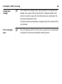
6.2
Intended Use
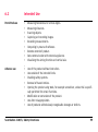
Permitted use
•
•
•
•
•
•
•
•
•
Measuring horizontal and vertical angles.
Measuring distances.
Scanning objects.
Capturing and recording images.
Recording measurements.
Computing by means of software.
Remote control of product.
Data communication with external appliances.
Visualising the aiming direction and vertical axis.
Adverse use
•
•
•
•
•
Use of the product without instruction.
Use outside of the intended limits.
Disabling safety systems.
Removal of hazard notices.
Opening the product using tools, for example screwdriver, unless this is specifically permitted for certain functions.
Modification or conversion of the product.
Use after misappropriation.
Use of products with obviously recognisable damages or defects.
•
•
•
ScanStation C10/C5, Safety Directions
99
ScanStation C10/C5, Safety Directions
•
•
•
•
Warning
100
Use with accessories from other manufacturers without the prior explicit
approval of Leica Geosystems.
Inadequate safeguards at the surveying site, for example when measuring on
roads.
Deliberate dazzling of third parties.
Controlling of machines, moving objects or similar monitoring application without
additional control- and safety installations.
Adverse use can lead to injury, malfunction and damage.
It is the task of the person responsible for the equipment to inform the user about
hazards and how to counteract them. The product is not to be operated until the user
has been instructed on how to work with it.
6.3
Limits of Use
Environment
Suitable for use in an atmosphere appropriate for permanent human habitation: not
suitable for use in aggressive or explosive environments.
Danger
Environment
Local safety authorities and safety experts must be contacted before working in
hazardous areas, or in close proximity to electrical installations or similar situations
by the person in charge of the product.
For GEV225 / GEV230
Suitable for use in dry environment only and not under adverse conditions.
ScanStation C10/C5, Safety Directions
101
ScanStation C10/C5, Safety Directions
102
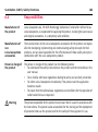
6.4
Responsibilities
Manufacturer of
the product
Leica Geosystems AG, CH-9435 Heerbrugg, Switzerland, hereinafter referred to as
Leica Geosystems, is responsible for supplying the product, including the user manual
and original accessories, in a completely safe condition.
Manufacturers of
non
Leica Geosystems
accessories
The manufacturers of non Leica Geosystems accessories for the product are responsible for developing, implementing and communicating safety concepts for their
products, and are also responsible for the effectiveness of those safety concepts in
combination with the Leica Geosystems product.
Person in charge of
the product
The person in charge of the product has the following duties:
• To understand the safety instructions on the product and the instructions in the
user manual.
• To be familiar with local regulations relating to safety and accident prevention.
• To inform Leica Geosystems immediately if the product and the application
becomes unsafe.
• To ensure that the national laws, regulations and conditions for the operation of
radio transmitters are respected.
Warning
The person responsible for the product must ensure that it is used in accordance with
the instructions. This person is also accountable for the training and the deployment
of personnel who use the product and for the safety of the equipment in use.
6.5
Warning
Caution
Caution
Hazards of Use
The absence of instruction, or the inadequate imparting of instruction, can lead to
incorrect or adverse use, and can give rise to accidents with far-reaching human,
material, financial and environmental consequences.
Precautions:
All users must follow the safety directions given by the manufacturer and the directions of the person responsible for the product.
Watch out for erroneous measurement results if the product has been dropped or
has been misused, modified, stored for long periods or transported.
Precautions:
Periodically carry out test measurements and perform the field adjustments indicated
in the user manual, particularly after the product has been subjected to abnormal use
and before and after important measurements.
During the operation of the product there is a hazard of squeezing extremities or
entanglement of hairs and/or clothes by rotating parts.
Precautions:
Keep a safe distance of the rotating parts.
ScanStation C10/C5, Safety Directions
103
ScanStation C10/C5, Safety Directions
Danger
Warning
Warning
104
Because of the risk of electrocution, it is very dangerous to use poles and extensions
in the vicinity of electrical installations such as power cables or electrical railways.
Precautions:
Keep at a safe distance from electrical installations. If it is essential to work in this
environment, first contact the safety authorities responsible for the electrical installations and follow their instructions.
If the product is used with accessories, for example masts, staffs, poles, you may
increase the risk of being struck by lightning.
Precautions:
Do not use the product in a thunderstorm.
During dynamic applications, for example stakeout procedures, there is a danger of
accidents occurring if the user does not pay attention to the environmental conditions around, for example obstacles, excavations or traffic.
Precautions:
The person responsible for the product must make all users fully aware of the existing
dangers.
Warning
Warning
Caution
Inadequate securing of the surveying site can lead to dangerous situations, for
example in traffic, on building sites, and at industrial installations.
Precautions:
Always ensure that the survey site is adequately secured. Adhere to the regulations
governing safety and accident prevention and road traffic.
If computers intended for use indoors are used in the field there is a danger of electric shock.
Precautions:
Adhere to the instructions given by the computer manufacturer with regard to field
use in conjunction with Leica Geosystems products.
If the accessories used with the product are not properly secured and the product is
subjected to mechanical shock, for example blows or falling, the product may be
damaged or people may sustain injury.
Precautions:
When setting-up the product, make sure that the accessories, for example tripod,
tribrach, connecting cables, are correctly adapted, fitted, secured, and locked in position.
Avoid subjecting the product to mechanical stress.
ScanStation C10/C5, Safety Directions
105
ScanStation C10/C5, Safety Directions
Warning
Caution
Warning
Warning
106
Only Leica Geosystems authorised service workshops are entitled to repair these
products.
With the remote control of products, it is possible that extraneous targets will be
picked out and measured.
Precautions:
When measuring in remote control mode, always check your results for plausibility.
Using a battery charger not recommended by Leica Geosystems can destroy the
batteries. This can cause fire or explosions.
Precautions:
Only use chargers recommended by Leica Geosystems to charge the batteries.
High mechanical stress, high ambient temperatures or immersion into fluids can
cause leakage, fire or explosions of the batteries.
Precautions:
Protect the batteries from mechanical influences and high ambient temperatures. Do
not drop or immerse batteries into fluids.
Warning
Caution
Short circuited battery terminals can overheat and cause injury or fire, for example
by storing or transporting in pockets if battery terminals come in contact with jewellery, keys, metallised paper or other metals.
Precautions:
Make sure that the battery terminals do not come into contact with metallic objects.
During the transport, shipping or disposal of batteries, it is possible for inappropriate
mechanical influences to constitute a fire hazard.
Precautions:
When transporting shipping, or disposing batteries, the person in charge of the
product must ensure that the applicable national and international rules and regulations are observed. Before transportation or shipping contact your local passenger
or freight transport company.
For Power Supply:
Danger
Death or serious injury can occur if unit is not connected to ground.
To avoid electric shock power cable and outlet must be grounded.
ScanStation C10/C5, Safety Directions
107
ScanStation C10/C5, Safety Directions
Danger
Warning
Warning
108
The product is not designed for use under wet and severe conditions. If unit becomes
wet it may cause you to receive an electric shock.
Precautions:
Use the product only in dry environments, for example in buildings or vehicles.
Protect the product against humidity. If the product becomes humid, it must not be
used!
If you open the product, either of the following actions may cause you to receive an
electric shock:
• Touching live components.
• Using the product after incorrect attempts were made to carry out repairs.
Precautions:
Do not open the product. Only Leica Geosystems authorised service workshops are
entitled to repair these products.
Batteries not recommended by Leica Geosystems may be damaged if charged or
discharged. They may burn and explode.
Precautions:
Only charge and discharge batteries recommended by Leica Geosystems.
Warning
If the product is improperly disposed of, the following can happen:
• If polymer parts are burnt, poisonous gases are produced which may impair
health.
• If batteries are damaged or are heated strongly, they can explode and cause
poisoning, burning, corrosion or environmental contamination.
• By disposing of the product irresponsibly you may enable unauthorised persons
to use it in contravention of the regulations, exposing themselves and third
parties to the risk of severe injury and rendering the environment liable to
contamination.
• Improper disposal of silicone oil may cause environmental contamination.
Precautions:
The product must not be disposed of with household waste.
Dispose of the product appropriately in accordance with the national
regulations in force in your country.
Always prevent access to the product by unauthorised personnel.
Product specific treatment and waste management information can be downloaded
from the Leica Geosystems home page at http://www.leica-geosystems.com/treatment
or received from your Leica Geosystems dealer.
ScanStation C10/C5, Safety Directions
109
ScanStation C10/C5, Safety Directions
110
6.6
Laser Classification, Visible Laser
6.6.1
General
General
The following directions (in accordance with the state of the art - international
standard IEC 60825-1 (2007-03) and IEC TR 60825-14 (2004-02)) provide instruction and training information to the person responsible for the product and the
person who actually uses the equipment, to anticipate and avoid operational
hazards.
The person responsible for the product must ensure that all users understand these
directions and adhere to them.
Products classified as laser class 1, class 2 and class 3R do not require:
• laser safety officer involvement,
• protective clothes and eyewear,
• special warning signs in the laser working area
if used and operated as defined in this user manual due to the low eye
hazard level.
Products classified as laser class 2 or class 3R may cause dazzle, flashblindness and after-images, particularly under low ambient light conditions.
6.6.2
Distance Laser
General
The laser incorporated into the product produces a visible green laser beam which
emerges from the rotating mirror.
The laser product described in this section, is classified as laser class 3R in accordance with:
• IEC 60825-1 (2007-03): "Safety of laser products".
• EN 60825-1 (2007-10): "Safety of laser products".
Class 3R laser products:
Direct intrabeam viewing may be hazardous (low-level eye hazard), in particular for
deliberate ocular exposure. The risk of injury for laser class 3R products is limited
because of:
a) unintentional exposure would rarely reflect worst case conditions of (e.g.) beam
alignment with the pupil, worst case accommodation,
b) inherent safety margin in the maximum permissible exposure to laser radiation
(MPE),
c) natural aversion behaviour for exposure to bright light for the case of visible radiation.
ScanStation C10/C5, Safety Directions
111
112
ScanStation C10/C5, Safety Directions
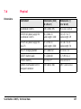
Description
Value
Maximum average radiant power
1.5 mW
Maximum peak radiant power
120 W
Pulse duration
250 ps
Pulse repetition frequency
Beam divergence (full angle)
Warning
50 kHz
0.1 mrad
Beam waist location
20 m
Beam waist diameter (1/e)
2.5 mm
NOHD (Nominal Ocular Hazard Distance) @ 0.25s
6 m / 19.7 ft.
From a safety perspective class 3R laser products should be treated as potentially
hazardous.
Precautions:
Prevent direct eye exposure to the beam. Do not direct the beam at other people.
Warning
Potential hazards are not only related to direct beams but also to reflected beams
aimed at reflecting surfaces such as prisms, windows, mirrors, metallic surfaces etc.
Precautions:
Do not aim at areas that are essentially reflective, such as a mirror, or which could
emit unwanted reflections. Do not look through or beside the optical sight at prisms
or reflecting objects when the laser is switched on, in laserpointer or distance measurement mode.
ScanStation C10/C5, Safety Directions
113
114
ScanStation C10/C5, Safety Directions
Labelling
Laser Aperture
a
Laser Radiation
Avoid direct eye exposure
Class 3R Laser Product
according to IEC 60825-1
( 2007 - 03 )
Pav = 1.5 mW
Ep = 30 nJ
λ = 532 nm
C10_029
a) Laser beam
Type: ScanStation....
Equip.No.: . . . . . . .
Power: . . . . .
Leica Geosystems AG
CH-9435 Heerbrugg
Manufactured: . . . .
25
Made in Switzerland
Art.No.: . . . . . .
S.No.: . . . . . .
Complies with FDA performance standards for laser
products except for deviations pursuant to Laser
Notice No. 50, dated June 24, 2007.
This device complies with part 15 of the FCC Rules.
Operation is subject to the following two conditions:
(1) This device may not cause harmful interference,
and (2) this device must accept any interference
received, including interference that may cause
undesired operation.
C10_030
ScanStation C10/C5, Safety Directions
115
116
ScanStation C10/C5, Safety Directions
6.6.3
Laser Plummet
General
The laser plummet built into the product produces a visible red laser beam which
emerges from the bottom of the product.
The laser product described in this section, is classified as laser class 2 in accordance
with:
• IEC 60825-1 (2007-03): "Safety of laser products"
• EN 60825-1 (2007-10): "Safety of laser products"
Class 2 laser products:
These products are safe for momentary exposures but can be hazardous for deliberate staring into the beam.
Description
Value
Maximum radiant power
1.00 mW
Pulse duration
0 - 100%
Pulse repetition frequency
1 kHz
Wavelength
620 nm - 690 nm
Warning
From a safety perspective class 2 laser products are not inherently safe for the eyes.
Precautions:
Avoid staring into the beam or pointing the beam at other people.
Labelling
Type: ScanStation....
Equip.No.: . . . . . . .
Power: . . . . .
Leica Geosystems AG
CH-9435 Heerbrugg
Manufactured: . . . .
25
Made in Switzerland
Art.No.: . . . . . .
S.No.: . . . . . .
Complies with FDA performance standards for laser
products except for deviations pursuant to Laser
Notice No. 50, dated June 24, 2007.
This device complies with part 15 of the FCC Rules.
Operation is subject to the following two conditions:
(1) This device may not cause harmful interference,
and (2) this device must accept any interference
received, including interference that may cause
undesired operation.
a
Laser Radiation
Do not stare into the beam
Class 2 Laser Product
according to IEC 60825-1
( 2007-03 )
Po ≤ 1.00 mW
λ = 620 - 690 nm
C10_031
a) Class 2 laser warning label is not applied because distance laser is of a higher
laser class.
ScanStation C10/C5, Safety Directions
117
118
ScanStation C10/C5, Safety Directions
b
a
C10_032
a) Laser beam
b) Exit for laser beam
6.7
Electromagnetic Compatibility EMC
Description
The term Electromagnetic Compatibility is taken to mean the capability of the product
to function smoothly in an environment where electromagnetic radiation and electrostatic discharges are present, and without causing electromagnetic disturbances
to other equipment.
Warning
Electromagnetic radiation can cause disturbances in other equipment.
Although the product meets the strict regulations and standards which are in force
in this respect, Leica Geosystems cannot completely exclude the possibility that other
equipment may be disturbed.
Caution
There is a risk that disturbances may be caused in other equipment if the product is
used in conjunction with accessories from other manufacturers, for example field
computers, personal computers, two-way radios, non-standard cables or external
batteries.
Precautions:
Use only the equipment and accessories recommended by Leica Geosystems. When
combined with the product, they meet the strict requirements stipulated by the guidelines and standards. When using computers and two-way radios, pay attention to the
information about electromagnetic compatibility provided by the manufacturer.
ScanStation C10/C5, Safety Directions
119
ScanStation C10/C5, Safety Directions
Caution
Warning
120
Disturbances caused by electromagnetic radiation can result in erroneous measurements.
Although the product meets the strict regulations and standards which are in force
in this respect, Leica Geosystems cannot completely exclude the possibility that the
product may be disturbed by very intense electromagnetic radiation, for example,
near radio transmitters, two-way radios or diesel generators.
Precautions:
Check the plausibility of results obtained under these conditions.
If the product is operated with connecting cables attached at only one of their two
ends, for example external supply cables, interface cables, the permitted level of
electromagnetic radiation may be exceeded and the correct functioning of other
products may be impaired.
Precautions:
While the product is in use, connecting cables, for example product to external
battery, product to computer, must be connected at both ends.
Warning
Electromagnetic fields can cause disturbances in other equipment, in installations, in
medical devices, for example pacemakers or hearing aids and in aircraft. It can also
affect humans and animals.
Precautions:
Although the product meets the strict regulations and standards which are in force
in this respect, Leica Geosystems cannot completely exclude the possibility that other
equipment may be disturbed or that humans or animals may be affected.
• Do not operate the product with radio or digital cellular phone devices in the
vicinity of filling stations or chemical installations, or in other areas where an
explosion hazard exists.
• Do not operate the product with radio or digital cellular phone devices near to
medical equipment.
• Do not operate the product with radio or digital cellular phone devices in aircraft.
ScanStation C10/C5, Safety Directions
121
ScanStation C10/C5, Safety Directions
122
6.8
FCC Statement, Applicable in U.S.
Applicability
The greyed paragraph below is only applicable for products of the ScanStation C10/C5
System without radio, digital cellular phone devices or Bluetooth.
Warning
This equipment has been tested and found to comply with the limits for a Class B
digital device, pursuant to part 15 of the FCC rules.
These limits are designed to provide reasonable protection against harmful interference in a residential installation.
This equipment generates, uses and can radiate radio frequency energy and, if not
installed and used in accordance with the instructions, may cause harmful interference to radio communications. However, there is no guarantee that interference will
not occur in a particular installation.
If this equipment does cause harmful interference to radio or television reception,
which can be determined by turning the equipment off and on, the user is encouraged to try to correct the interference by one or more of the following measures:
•
•
•
Reorient or relocate the receiving antenna.
Increase the separation between the equipment and the receiver.
Connect the equipment into an outlet on a circuit different from that to which
the receiver is connected.
•
Consult the dealer or an experienced radio/TV technician for help.
Warning
Changes or modifications not expressly approved by Leica Geosystems for compliance could void the user's authority to operate the equipment.
Labelling
ScanStation C10/C5
..................
..................
........ .....
..................
..................
..................
..................
Art.No.: . . . . . . . .
S.No.: . . . . . . . . .
25
This device complies with part 15 of the FCC
Rules. Operation is subject to the following two
conditions: (1) This device may not cause
harmful interference, and (2) this device must
accept any interference received, including
interference that may cause undesired
operation.
C10_033
ScanStation C10/C5, Safety Directions
123
124
ScanStation C10/C5, Safety Directions
Labelling GEB241
..
.... ........
.... ....
.... ....
..
....
.... ........
....
....
.... ........ .... ..
..
....
.... ........
.... ......
.... ....
....
.... .
.... ........
....
.... ................
.... .. ...
....
.... ........
....
.... ........
....
.... ........
..
.... ........
....
.... ...
....
....
..
This device complies with part 15 of the FCC Rules. Operation
is subject to the following two conditions: (1) This device
may not cause harmful interference, and (2) this device
must accept any interference received, including
interference that may cause undesired operation.
C10_034
Labelling GKL212
Labelling GKL221
Type: GKL221
Art.No.: .......
.....................................................................
..................................................
........................
..................................................
.........................................
.......................................
...............................
.................................
This device complies with part 15 of the FCC Rules. Operation
is subject to the following two conditions: (1) This device may
not cause harmful interference, and (2) this device must
accept any interference received, including interference that
may cause undesired operation.
GKL221_013
ScanStation C10/C5, Safety Directions
125
126
ScanStation C10/C5, Safety Directions
Labelling GEB271
...................
..........................
.....................
..............
Labelling GKL271
ScanStation C10/C5, Safety Directions
....................
....................
....................
....................
....................
...........
...........
...........
127
ScanStation C10/C5, Technical Data
128
7
Technical Data
7.1
General Technical Data of the Instrument
Instrument type
Compact, pulsed, dual-axis compensated, very high-speed laser scanner, with surveygrade accuracy, range, and field of view; integrated camera and laser plummet
User interface
Onboard control, notebook, Tablet PC or remote controller
Data storage
Integrated 80 GB solid state drive, external PC or external USB device
Camera
Auto-adjusting, integrated high-resolution digital camera with zoom video. External
SLR camera (optional).
7.2
System Performance
Accuracy of single
measurement
Position1:
6 mm
Distance1:
Angle (horizontal/vertical):
4 mm
12" / 12" (60 μrad / 60 μrad)
Modeled surface
precision2/noise
2 mm
Target acquisition3
2 mm standard deviation
Dual-axis
compensator4
Selectable on/off;
Setting accuracy: 1.5" / 7.275 μrad, resolution 1", dynamic range ±5'
All ± accuracy specifications are one sigma (1 σ) unless otherwise noted.
1
At 1 m - 50 m range, 1 σ
2
Subject to modeling methodology for modeled surface
3
Algorithmic fit to planar HDS targets
4
Optional for C5
ScanStation C10/C5, Technical Data
129
130
ScanStation C10/C5, Technical Data
7.3
Laser Scanning System
Type
Pulsed; proprietary microchip
Color
Green; visible (wavelength = 532 nm)
Range
C10:
C5:
300 m @ 90%; 134 m @ 18% albedo (minimum range 0.1 m)
35 m @ 5% albedo (upgradeable to full C10 range)
Scan rate
C10:
C5:
up to 50’000 points/sec, maximum instantaneous rate
25'000 points/sec (upgradable to full C10 speed)
Scan resolution
Spot size:
Point spacing:
7 mm from 0 - 50 m (based on Gaussian definition)
4.5 mm from 0 -50 m (based on FWHH definition)
Independently, fully selectable vertical and horizontal pointto-point measurement spacing
Fully selectable horizontal & vertical; through full range
Horizontal:
Vertical:
Aiming/Sighting:
360° (maximum)
270° (maximum)
Parallax-free, integrated zoom video
Selectability:
Field-of-View
(per scan)
Scanning Optics
Vertically rotating mirror on horizontally rotating base;
Smart X-Mirror™ automatically spins or oscillates for minimum scan time
Scan motors
Direct drive, brushless
Communication
Dynamic Internet Protocol (IP) address via Ethernet or wireless LAN (WLAN) with
external adapter
Integrated digital
color camera with
zoom video
•
External SLR
camera (optional)
•
•
Full 360° x 270° dome: Streaming video with zoom, auto-adjusts to ambient
lighting
Single 17° x 17° image: 1920 x 1920 pixels (4 megapixel)*
Full 360° x 270° dome: 260 images, automatically spatially rectified*
*
Optional for C5
•
•
•
Canon EOS 60D camera with Sigma 8mm F3.5 EX DG fisheye lense
Single image: 3456 x 5184 pixels (18 megapixels)
Full 360° x 270° dome: 6 images, automatically spatially rectified
For details refer to the external camera manual.
Onboard display
Touchscreen control with stylus, full color graphic display, QVGA (320 x 240 pixels)
ScanStation C10/C5, Technical Data
131
132
ScanStation C10/C5, Technical Data
Level indicator
External bubble, electronic bubble in onboard control and Cyclone software
Laser plummet
Type:
Location:
Accuracy:
Diameter of laser point:
Visible red laser class 2
In standing axis of instrument
Deviation from plumbline:
1.5 mm at 1.5 m instrument height
2.5 mm at 1.5 m instrument height
7.4
Electrical
Power supply
15 V DC, 90 - 260 V AC;
Four internal batteries provided with system.
Power
consumption
<50 W, average
GEV230 AC power
supply for
ScanStation C10/C5
Input voltage:
Output voltage:
Power ports
Internal: 2, External: 1 (simultaneous use, hot swappable)
GEV225 AC power
supply for GKL271
Input voltage:
Output voltage:
100-240 V AC, 50-60 Hz
24 V
GKL271 charging
station
Input voltage:
Output voltage:
Port P3: 24 V DC
Port P1: 14.4 V DC
Port P2: 24 V DC / 36 V DC
ScanStation C10/C5, Technical Data
100-240 V AC, 50-60 Hz
15 V
133
134
ScanStation C10/C5, Technical Data
GEB271 battery
pack
Type:
Voltage:
Capacity:
Li-Ion
14.4 V
16.8 Ah
GEB241 battery
Type:
Voltage:
Capacity:
Li-Ion
14.8 V
4.8 Ah
Operating time
Internal batteries:
>3.5 hours, typical continuous use (room temperature),
using both batteries simultaneously
>6 hours, typical continous use (room temperature)
External battery:
Charging time
Internal batteries:
External batteries:
Typical charging time with Professional Charger GKL221 is
<3.5 h at room temperature (2 batteries).
Typical charging time is 3.5 h at room temperature.
7.5
Environmental
7.5.1
Scanner
Environmental
specifications
Temperature
Type
Operating temperature [°C] Storage temperature [°C]
ScanStation C10/C5
0 to +40
-25 to +65
A/C power supply
0 to +40
-25 to +65
Protection against water, dust and sand
IP54 (IEC 60529)
Humidity
Max 95 % non condensing
Lighting
Fully operational from bright sunlight to complete darkness.
ScanStation C10/C5, Technical Data
135
136
ScanStation C10/C5, Technical Data
7.5.2
GEB271 / GKL271 / GEB241
Environmental
specifications
Temperature
Operating temperature [°C]
Mode
0 to +45
Charging
-20 to +55
Discharging
Storage temperature [°C]
Mode
Recharging needed after
-40 to +70
Standard
6 months
Protection against water and dust
IP54 (IEC 60529)
Humidity
Max 95% non-condensing
7.6
Dimensions
Physical
Instrument
Dimensions [mm]
(D x W x H)
Dimensions ["]
(D x W x H)
ScanStation C10/C5
238 x 358 x 395
9.4 x 14.1 x 15.6
GEV230 AC power supply for
ScanStation C10/C5
76 x 146 x 43
Cable length: 1000
3.0 x 5.7 x 1.7
Cable length: 39
GEV225 AC power supply for
GKL271
85 x 170 x 41
Cable length: 1800
3.4 x 6.7 x 1.6
Cable length: 70
GKL271 charging station
127 x 264 x 82
5 x 10.4 x 3.2
GEB271 battery pack
95 x 248 x 60
3.7 x 9.8 x 2.4
GEB241 battery
40 x 72 x 77
1.6 x 2.8 x 3.0
GVP645 ScanStation C10/C5
transport container
500 x 625 x 366
19.7 x 24.6 x 14.4
ScanStation C10/C5, Technical Data
137
138
ScanStation C10/C5, Technical Data
ScanStation C10/C5 with GS15
antenna (with handle GAD110)
117.5
229
ScanStation C10/C5 with GRZ122
prism (with handle GAD110 and
adapter GAD112)
C10_044
Type
250
250
Tilt axis height and
offset to TPS/GNSS
accessories
C10_043
GRZ122 / GAD110 / GAD112
Tilt axis height 250 mm
GS15 / GAD110
250 mm
Offset tilt axis 229 mm to prism center.
117.5 mm to GS15 antenna
Valid for all Leica standard prisms MRP (Mechanical Reference
with an height offset of 86 mm. Plane).
ScanStation C10/C5 with ATX1230+
antenna (with handle GAD104)
C10_042
Type
250
250
158.4
269
ScanStation C10/C5 with GRZ122
prism (with handle GAD104 and
adapter GAD111)
C10_041
GRZ122 / GAD104
Tilt axis height 250 mm
ATX1230+ / GAD104
250 mm
Offset tilt axis 269 mm to prism center.
158.4 mm to ATX1230+
Valid for all Leica standard prisms antenna MRP (Mechanical
with an height offset of 86 mm. Reference Plane).
ScanStation C10/C5, Technical Data
139
140
ScanStation C10/C5, Technical Data
37.5
ScanStation C10/C5 with
HDS target 3" (with GRT146 carrier)
250
60.5
ScanStation C10/C5 with
HDS target 6" (with GRT146 carrier)
250
Tilt axis height and
offset to targets
Type
HDS target 6"
(with GRT146 carrier)
HDS target 3"
(with GRT146 carrier)
Tilt axis height 250 mm
250 mm
Offset tilt axis 60.5 mm to target center.
37.5 mm to target center.
Weight
Instrument
Weight [kg]
Weight [lbs]
ScanStation C10/C5
13, nominal
28.7, nominal
GEV230 AC power supply for
ScanStation C10/C5
0.7
1.5
GEV225 AC power supply for GKL271
0.860
1.9
GKL271 charging station
1
2.2
GEB271 battery pack
1.9
4.2
GEB241 battery
0.4
0.9
GVP645 ScanStation C10/C5 transport
container (without scanner and accessories)
10.4
22.9
GVP645 ScanStation C10/C5 transport
container (with scanner and standard
deliverables)
28
61.7
ScanStation C10/C5, Technical Data
141
ScanStation C10/C5, Technical Data
7.7
Accessories
Standard Accessories, included
•
•
•
•
•
•
•
•
•
Transport container for scanner
Tribrach (Leica Professional Series)
Internal battery (4x)
Battery charger with AC power cable, car adapter, daisy chain cable
Ethernet cable
Height meter and distance holder for height meter
Cleaning tissue
Cyclone™ SCAN software
1 year CCP Basic support agreement
Additional
accessories
•
•
•
•
•
•
•
•
•
HDS scan targets and target accessories
Service agreement for Leica ScanStation C10/C5
Extended warranty for Leica ScanStation C10/C5
External battery with charging station, AC power supply and power cable
Professional charger for internal batteries
AC power supply for scanner
Tripod, tripod star, rolling base, external wireless LAN adapter (third-party)
External camera kit with bracket and connection cable to scanner
External camera (third-party)
142
Notebook PC for
scanning
Component
Minimum requirements
Processor
2 GHz Dual Core processor or better
System memory RAM
2 GB (4 GB for Windows Vista or Windows7)
Hard Disk
40GB or greater, (5’400RPM or faster)
Network connection
Ethernet
Display
SVGA or OpenGL accelerated graphics card (with latest
drivers)
Operating system
•
•
•
File System
NTFS
*
Microsoft Vista* (32 or 64)
Microsoft Windows XP (SP2 or higher) (32 or 64)
Microsoft Windows 7 (32 or 64)
Some systems may not support Windows Vista‘s Desktop Windows Manager
(DWM) with Leica Cyclone and must be operated in Windows Classic Look.
Minimum requirements for modeling operations are different. Please refer to
Cyclone datasheet for specifications, available at your Leica Geosystems
dealer.
ScanStation C10/C5, Technical Data
143
ScanStation C10/C5, International Limited Warranty, Software License Agreement
144
8
International Limited Warranty, Software
License Agreement
International
Limited Warranty
This product is subject to the terms and conditions set out in the International
Limited Warranty which you can download from the Leica Geosystems home page at
http://www.leica-geosystems.com/internationalwarranty or collect from your Leica
Geosystems distributor.
The foregoing warranty is exclusive and is in lieu of all other warranties, terms or
conditions, express or implied, either in fact or by operation of law, statutory or
otherwise, including warranties, terms or conditions of merchantability, fitness for a
particular purpose, satisfactory quality and non-infringement, all of which are
expressly disclaimed.
Software License
Agreement
This product contains software that is preinstalled on the product, or that is supplied
to you on a data carrier medium, or that can be downloaded by you online pursuant
to prior authorisation from Leica Geosystems. Such software is protected by copyright and other laws and its use is defined and regulated by the Leica Geosystems
Software License Agreement, which covers aspects such as, but not limited to, Scope
of the License, Warranty, Intellectual Property Rights, Limitation of Liability, Exclusion
of other Assurances, Governing Law and Place of Jurisdiction. Please make sure, that
at any time you fully comply with the terms and conditions of the Leica Geosystems
Software License Agreement.
Such agreement is provided together with all products and can also be referred to
and downloaded at the Leica Geosystems home page at
http://www.leica-geosystems.com/swlicense or collected from your Leica Geosystems
distributor.
You must not install or use the software unless you have read and accepted the
terms and conditions of the Leica Geosystems Software License Agreement. Installation or use of the software or any part thereof, is deemed to be an acceptance of all
the terms and conditions of such License Agreement. If you do not agree to all or
some of the terms of such License Agreement, you may not download, install or use
the software and you must return the unused software together with its accompanying documentation and the purchase receipt to the dealer from whom you
purchased the product within ten (10) days of purchase to obtain a full refund of the
purchase price.
ScanStation C10/C5, International Limited Warranty, Software License Agreement
145
ScanStation C10/C5, Microsoft End User License Agreement ("EULA")
146
9
Microsoft End User License Agreement ("EULA")
END USER LICENSE
AGREEMENT FOR
MICROSOFT
EMBEDDED
SYSTEMS
•
•
•
You have acquired a device ("DEVICE") that includes software licensed by Leica
Geosystems from Microsoft Licensing, GP or its affiliates ("MS"). Those installed
software products of MS origin, as well as associated media, printed materials,
and "online" or electronic documentation ("SOFTWARE") are protected by international intellectual property laws and treaties. The SOFTWARE is licensed, not
sold. All rights reserved.
IF YOU DO NOT AGREE TO THIS END USER LICENSE AGREEMENT ("EULA"), DO NOT
USE THE DEVICE OR COPY THE SOFTWARE. INSTEAD, PROMPTLY CONTACT LEICA
GEOSYSTEMS FOR INSTRUCTIONS ON RETURN OF THE UNUSED DEVICE(S) FOR A
REFUND. ANY USE OF THE SOFTWARE, INCLUDING BUT NOT LIMITED TO USE
ON THE DEVICE, WILL CONSTITUTE YOUR AGREEMENT TO THIS EULA (OR
RATIFICATION OF ANY PREVIOUS CONSENT).
GRANT OF SOFTWARE LICENSE. This EULA grants you the following license:
• You may use the SOFTWARE only on the DEVICE.
• NOT FAULT TOLERANT. THE SOFTWARE IS NOT FAULT TOLERANT. LEICA
GEOSYSTEMS HAS INDEPENDENTLY DETERMINED HOW TO USE THE SOFTWARE
IN THE DEVICE, AND MS HAS RELIED UPON LEICA GEOSYSTEMS TO CONDUCT
SUFFICIENT TESTING TO DETERMINE THAT THE SOFTWARE IS SUITABLE FOR
SUCH USE.
• NO WARRANTIES FOR THE SOFTWARE. THE SOFTWARE is provided "AS IS"
and with all faults. THE ENTIRE RISK AS TO SATISFACTORY QUALITY, PERFORMANCE, ACCURACY, AND EFFORT (INCLUDING LACK OF NEGLICENCE) IS WITH YOU.
ALSO, THERE IS NO WARRANTY AGAINST INTERFERENCE WITH YOUR ENJOYMENT OF THE SOFTWARE OR AGAINST INFRINGEMENT. IF YOU HAVE RECEIVED
ANY WARRANTIES REGARDING THE DEVICE OR THE SOFTWARE, THOSE
WARRANTIES DO NOT ORIGINATE FROM, AND ARE NOT BINDING ON, MS.
• No Liability for Certain Damages. EXCEPT AS PROHIBITED BY LAW, MS
SHALL HAVE NO LIABILITY FOR ANY INDIRECT, SPECIAL, CONSEQUENTIAL
OR INCIDENTAL DAMAGES ARISING FROM OR IN CONNECTION WITH THE
USE OR PERFORMANCE OF THE SOFTWARE. THIS LIMITATION SHALL
APPLY EVEN IF ANY REMEDY FAILS OF ITS ESSENTIAL PURPOSE, IN NO
EVENT SHALL MS BE LIABILE FOR ANY AMOUNT IN EXCESS OF U.S. TWO
HUNDRED FIFTY DOLLARS (U.S.$250.00).
• Limitations on Reverse Engineering, Decompilation, and Disassembly.
You may not reverse engineer, decompile, or disassemble the SOFTWARE,
except and only to the extent that such activity is expressly permitted by applicable law notwithstanding this limitation.
• SOFTWARE TRANSFER ALLOWED BUT WITH RESTRICTIONS. You may
permanently transfer rights under this EULA only as part of a permanent sale
or transfer of the Device, and only if the recipient agrees to this EULA. If the
SOFTWARE is an upgrade, any transfer must also include all prior versions of
the SOFTWARE.
ScanStation C10/C5, Microsoft End User License Agreement ("EULA")
147
ScanStation C10/C5, Microsoft End User License Agreement ("EULA")
148
• EXPORT RESTRICTIONS. You acknowledge that SOFTWARE is subject to U.S.
export jurisdiction. You agree to comply with all applicable international and
national laws that apply to the SOFTWARE, including the U.S. Export Administration Regulations, as well as end-user, end-use and destination restrictions
issued by U.S. and other governments. For additional information see
http://www.microsoft.com/exporting/.
ScanStation C10/C5, Microsoft End User License Agreement ("EULA")
149
ScanStation C10/C5, Index
150
Index
A
AC power supply ............................... 18, 21, 23, 35
Accuracy ........................................................... 129
Adjustment
Of circular level on instrument ....................... 92
Of circular level on tribrach ............................ 93
B
Battery, external ................................... 15, 61, 134
Battery, internal .................................... 13, 60, 134
Beam divergence .............................................. 112
C
Camera, external ............................................... 131
Camera, internal ............................................... 131
Charging external battery .................................... 52
Charging internal battery .................................... 58
Charging time ................................................... 134
Circular level ................................................. 12, 92
Compensator, dual-axis ............................... 73, 129
D
Dimensions .......................................................137
F
Field of View (FoV) ......................................26, 130
H
HDS Cyclone Software Suite ................................39
I
Instrument Height ...............................................48
K
Keyboard
Virtual ............................................................37
L
Laptop ................................................................11
Laser class ........................................................114
Distance laser ..............................................111
Visible laser ..................................................110
Laser plummet ....................................73, 116, 132
M
Message bar ....................................................... 28
O
Operate the instrument
With the power supply ............................. 20, 61
Operating time ................................................. 134
P
Power cable ........................................................ 11
R
Range ............................................................... 130
Transport container ...............................................8
Tripod .................................................................11
Tripod, service of ................................................94
U
USB socket ....................................................12, 27
W
Weight ..............................................................141
WiFi .....................................................................73
Communication device ....................................73
S
Scan rate .......................................................... 130
Scan resolution ................................................. 130
ScanStation C10 Laser Scanner ........................... 11
Service of tripod ................................................. 94
Set up the tripod .......................................... 43, 46
Status bar ........................................................... 28
T
Temperature ............................................. 135, 136
Title bar .............................................................. 28
ScanStation C10/C5, Index
151
Original text
Printed in Switzerland © 2012 Leica Geosystems AG, Heerbrugg, Switzerland
774311-5.0.0en
Leica Geosystems AG
Heinrich-Wild-Strasse
CH-9435 Heerbrugg
Switzerland
Phone +41 71 727 31 31
www.leica-geosystems.com