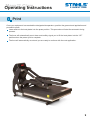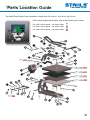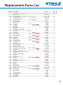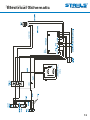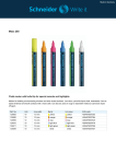
1
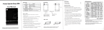
Maxx™ Clam
28x38 cm • 38x38 cm • 40x50 cm
O P E R ATO R ’ S
M A N U A L
40x50 cm
28x38 cm
38x38 cm
www.stahls.eu
Maxx™
Clam
Important
Safety Instructions
Important Safety Instructions
WHEN USING YOUR APPLIANCE, BASIC PRE-CAUTIONS SHOULD ALWAYS BE FOLLOWED,
INCLUDING THE FOLLOWING:
Read all instructions.
Use appliance only for its intended use.
To reduce the risk of electric shock, do not immerse the appliance in water or other liquids.
Never pull cord to disconnect from outlet, instead grasp plug and pull to disconnect.
Do not allow cord to touch hot surfaces, let appliance cool completely before putting away.
Do not operate appliance with a damaged cord, or if the appliance has been dropped or
damaged. To reduce the risk of electric shock, do not disassemble or attempt to repair the
appliance, take it to a qualified service person for examination and repair. Incorrect reassembly
or repair could cause a risk of fire, electric shock, or injury to persons when the appliance is used.
Close supervision is necessary for any appliance being used by or near children.
Do not leave appliance unattended while connected.
Burns could occur from touching hot metal parts.
To reduce the likelihood of circuit overload, do not operate another high voltage appliance on
the same circuit.
If an extension cord is absolutely necessary, a 20 ampere rated cord should be used.
Cords rated for less amperage may overheat, care should be taken to arrange the cord so
that the cord cannot be pulled or tripped over.
SAVE THESE INSTRUCTIONS.
1
Maxx™
Clam
Table of
Contents
Digital Part Location Guide
3
Maxx™ Clam Control Panel
4
Operating Instructions
5-9
Parts Location Guide
10
Parts List
11
Maxx™ Clam electrical Schematic
12
CE-Certification
13
Terms of guarantee
14
2
Maxx™
Clam
Machine
View
SIDE VIEW
Over-the-Centre
Pressure Adjustment Knop
Power ON/OFF
Switch
Lift Handle
ON
OFF
FRONT VIEW
LED Display
Located on the opposite side of the press
Power Supply
Circuit
Breaker
3
Maxx™
Clam
Control
Panel
CONTROL PANEL
Digital Display
Temp Indicator
TEMP
SET
Set Indicator
TIME
MODE
Time Indicator
“Increase” Button
“Mode” Button
“Decrease” Button
4
Maxx™
Clam
Operating
Instructions
The Digital CLAM BASIC Operating Instructions are designed with you in mind. Carefully read and
follow the step-by-step instructions for best results.
If you experience any difficulty, carefully re-read the instructions and try again.
Pay particular attention to the risk of burns which can be sustained by touching the heated
platen during use.
Keep hands clear from the platens of the press during platen lock down as the pressure
can cause injury.
Press should be placed on a sturdy suitable stand of at least 60x90cms (24"x36").
Work area must be kept clean, tidy and free of obstructions to the movements of the heat press.
Power supply cord must be disconnected before cleaning or servicing press.
Connect the Power Cord
Connect the power cord into a properly grounded (earthed) electrical.
outlet with a sufficient amperage rating.
Your Maxx™ Clam requires a full 7,5 amp grounded circuit
for 240 volt operation.
Extension Cords, if used, should be as short as possible and not
less than 12 gauge. Heavy duty cords are recommended.
Circuits that have under 15 amps or other high demand
equipment or appliances (especially more than one heat seal
machine) should not be used.
NOTE:
If the supply cord is damaged, it must be replaced by the manufacturer or its service agent or a
similarly qualified person in order to avold hazard. Use HSJ type, rated 250V-10 AMP for replacement.
CAUTION
FAILURE TO FOLLOW THESE INSTRUCTIONS WILL CAUSE:
1. Erratic controller functions.
2. Inaccurate displays and slow heat-up.
3. The circuit breaker to disengage.
5
Maxx™
Clam
Operating
Instructions
Switch the system on
Locate the lift handle and position the heat platen in the up (load) position.
Locate the Power ON/OFF Switch on the press.
Turn the Power Switch on.
Power ON/OFF
Switch
ON
OFF
6
Maxx™
Clam
Adjust Temperature
& Time
Adjusting the Temperature
Adjust the tempeature
Locate the LED Display on the Press.
Press the Mode Select Button located in the centre of the Control Panel.
The (SET) and (TEMP) lights located next to the display will illuminate indicating you are in the adjust
temperature mode.
Next, press the (-) button located to the left of the Mode Select button to lower the temperature setting,
or press the (+) button located to the right of the Mode Select button to raise the temperature setting.
The temperature can be set from 205° F (96° C) to 430° F (220° C).
The LED will display changes as you make them.
Digital Display
Temperature Indicator
TEMP
SET
TIME
Set Indicator
MODE
Time Indicator
Increase
Mode Select
Decrease
NOTE: The temperature indicator will only display temperatures 200°F (93°C) and up.
4. Adjusting the Time
Adjust the time
Once you have adjusted the temperature, press the Mode Select button again. This will advance you
to the Time mode. The set and time lights will illuminate, indicating that you are in the Time mode.
Adjust the time in the same manner that you adjusted the temperature. Select the desired time and push
the Mode Select button again to exit the time settings. All lights will be off and the press will return to the
Print Mode.
7
Maxx™
Clam
Adjust Pressure
Adjusting the Pressure
The Maxx™ Press Digital Clam features a patented, Over-the-Centre Pressure Adjustment located
in the centre of the heat platen.
Adjust the pressure by turning the knob clockwise to increase pressure and counter clockwise to
decrease pressure.
REMEMBER:
To allow for the thickness of your garment when adjusting the pressure.
WARNING:
Structural damage caused by excessive pressure is not covered under the limited warranty!
Over-the-Centre
Pressure Adjustment Knob
8
Maxx™ Clam
Operating
Instructions
Print
Once your equipment has reached the designated temperature, position the garment and application and
proceed to press.
Lower and lock the heat platen into the press position. This procedure will start the automatic timing
process.
The timer will automatically count down and audibly signal you to lift the heat platen into the “UP”
position when the press cycle is complete.
The time will automatically re-set and you are ready to continue with the next application.
9
Maxx™
Clam Guide
Parts Location
The MAXX™ Press Digital Clam is available in three sizes: 28 x 38 cm, 38 x 38 cm, 40 x 50 cm
When ordering replacement parts, refer to the following color codes
For a 28 x 38 cm press - use colour code
A
For a 38 x 38 cm press - use colour code
B
For a 40 x 50 cm press - use colour code
C
26 A 26 C
20 A 20 B 20 C
19 A 19 B 19 C
18 A 18 B 18 C
17 A 17 B 17 C
7A
10 A 10 C
10
Maxx™
Clam Parts List
Replacement
Item #
Part Name
1
2
3
4 A-B
5
6
7 A-B
7C
8
9
10 A
10 B-C
11
12
13
14
15
16
17 A
17 B
17 C
18 A
18 B
18 C
19 A
19 B
19 C
20 A
20 B
20 C
21
22
23
24
25
26 A-B
26 C
27
28
29
30
31
32
33
34
35 A-B-C
36
37
38
39
40
41
42
43
44 A-B-C
45
46
47 A-B-C
48
49
50
51
52
53
54
55
56
Hex Soc Button HD # 10 - 32 x 1/2”
Rubber Foot
Acorn Hex Nut
Hex Cap HD Screw - 3/8“ -16 x 3/4” 16 x 20
Lock Spring Washer
Hex Soc Screw 1/4 - 20 x 1 1/4”
16 x 20
Lower Platen Spacer
Lower Platen Spacer
Nylon Hex Nut
Ball Stud - 10mm
16 x 20
Gas Spring
Gas Spring
Steel Spacer
Bridle Links
Nylon Washer
Threaded Pin 1/4” - 20 x 3”
PVC Spacer 1/2” I.D. x 2.48
Threaded Pin 3 5/8” x .5” Dia. _1/4” - 20
16 x 20
Lower Platen
Lower Platen
Lower Platen
16 x 20
Silicone Pad Gray
Silicone Pad Gray
Silicone Pad Gray
16 x 20
Heat Platen
Heat Platen
Heat Platen
16 x 20
Heat Platen Cover
Heat Platen Cover
Heat Platen Cover
Finish Washer
Cover Screw 10 - 24 x 1/2”
Adjustment Spindle
Pressure Adj. Knob
Safety Bolt “ - 18 x 4 1/2”
16 x 20
Elbow 90 degress with tubing
Topaz Connector with flex tubing
Shoulder Bolt
Steel Pin 1/2” Dia. x 4.38
Soc HD Cap Screw 1/4” - 20 x 3/8”
Hex HD Nut - 1/4 “ - 20
Steel Pin - 1/2” Dia. x 6.45
PVC Spacer - 1/2” 1.D. x 1.1
Nylon Nut
Rubber Foot
16 x 20
Adjustment Arm Assembly
JCN Nut
Foam Grip
PVC Spacer 1/2” I.D. x 5”
All Thread Pin - 1/4” - 20 x 4 3/4”
Lift Links
Hucap 1/2”
Magnet
Magnet Bracket
16 x 20
Handle Assembly
Phillips Pan HD Screw - #6-32 x 1/2”
Housing
16 x 20
Base Assembly
Proximity Switch
Terminal Block
Triac
Controller Bracket
SSTT Control Board
On/Off Switch
Circuit Breaker
Display Overlay
Probe
15 x 15
15 x 15
11 x 15
15 x 15 11 x 15
15 x 15
11 x 15
15 x 15
11 x 15
15 x 15
11 x 15
15 x 15
11 x 15
15 x 15
11 x 15
15 x 15 11 x 15
15 x 15 11 x 15
15 x 15 11 x 15
Part #
Qty.
3 - 1011 - 164
1 - 1256
3 - 1011 - 182
3 - 1011 - 41
2 - 1006 - 43
3 - 1011 - 62
1 - 1279
0140
2 - 1006 - 20
1 - 1939
1 - 2086
1 - 1874
1 - 2114
KIT 3 - 6906
1 - 1048 - 3
1 - 2091
1 - 2098
1 - 2092
2 - 1029
3 - 1086
3 - 1199 - 1
1 - 1011
1 - 1473
1 - 1875
2 - 1002 - 3
3 - 1320
3 - 1199
3 - 1332
3-1337
3 - 1331
1 - 1063
3 - 1011 - 217
2 - 1081
1 - 1012
3 - 1011 - 238
1 - 1940
1 - 1353
3 - 1011 - 55
1 - 2093
3 - 1011 - 215
2 - 1006 - 12
1 - 2094
1 - 2097
2 - 1006 - 20
1 - 1256
KIT 3 - 6903
2 - 1006 - 2
1-1540
1 - 2096
1 - 1042 - 1
KIT 3 - 6905
1 - 1107 - 1
1 - 1219
1 - 2085
KIT 3 - 6904
3 - 1011 - 152
4 - 1172
KIT 3 - 6901
1 - 1211
1 - 1290
1 - 1059
2 - 1661
1 - 2017
1 - 2087
1 - 1331
1 - 2018
1 - 1272 - 1
4
4
4
2
2
4
2
1
2
4
2
2
2
2
6
1
1
1
1
1
1
1
1
1
1
1
1
1
1
1
4
4
1
1
1
1
1
1
2
2
2
2
4
1
1
1
2
1
1
1
2
8
1
1
1
4
1
1
1
1
1
1
1
1
1
1
1
11
(1000 W for 11 x 15)
Maxx™
Clam
Electrical
Schematic
12
Maxx™
Clam
CE-Certification
EC conformance explanation:
For the purposes of the EC-Machine Guideline 98/37EU, Appendix 2A and the EC Low
Voltage directive to 73/23 European Economic Community as well as the EC EMV-guideline
89/336. For the manufacturer STAHLS’ Hotronix Division, we state as European
Commissioners, that our product:
A Transfer Press for ironing of thermo application.
Model: Maxx™ Clam
The product supplied corresponds to the following appropriate regulations:
EMC Directive (2004/108/EC) & Low voltage Directive (2006/95/EC)
Applied Harmonized norms
EN 55011:2007
EN 61000-6-1:2007
EN 61000-4-2:1995
EN 61000-4-3:2006
IEC 61000-3-2:2005
EN 61000-4-4:2004
EN 61000-4-5:2006
EN 61000-4-6:1996
EN 61000-4-11:2004
IEC 61000-3-3:1994
EN 61000-3-2:2006
EN 61000-3-3:1995
EN 60335-4:2004
EN 60335-2-44:2003
It is possible that not all the listed norms apply to the above mentioned product.
STAHLS’ Europe GmbH
(Frank Brücker, Chief Executive STAHLS’ Europe GmbH)
battery
WEE and RoHS Symbols
STAHLS’ Europe GmbH will take back ALL heat press machines
FREE OF CHARGE (inside the EU) that have been manufactured by them, even those
sold prior to the date stated above, subject to the heat press machine being delivered
to them at the owners costs.
STAHLS’ Europe GmbH will break down the heat press machine and ensure that all
recyclable parts are correctly recycled, and non-recyclable parts will be disposed of in
accordance with legal requirements. In an effort to make such transaction as smooth to
customers as is possible, and to ensure that all STAHLS’ heat presses are identifiable,
all heat press machines supplied by STAHLS’ Europe GmbH will have the logo/brand of
STAHLS’ Hotronix clearly marked upon them.
Contact:
STAHLS’ Europe GmbH, Dieselstraße 62, 66763 Dillingen, Germany
Telefon: +49 (0) 68 31/97 33-0, Fax: +49 (0) 68 31/97 33 45, www.stahls.de, [email protected]
13
Maxx™
Clam
Terms of
guarantee
Warranty Policy
STAHLS’ Europe GmbH provides the following warranty for the Maxx™ Clam, subject to the
following terms:
Duration
The warranty period of 2 years commences from the date of receipt by the buyer of the heat press
machine, which can be verified by the invoice or similar documents. The warranty does not cover any
damage caused by normal wear and tear.
Repair
If any parts are found to be defective, despite proper use, authorised use and not as a result of fair wear
and tear, within the warranty period, then they will be replaced or repaired without question provided that
STAHLS’ Europe GmbH have been informed of any such claim in writing within one week of the
occurrence of the failure. The terms and conditions of the commercial transaction are specifically
excluded from this warranty, especially §§377 et.seq. HGB. Following any claim under the warranty,
the warranty period will not be extended for either the heat press machine or for any replaced parts.
Any exchanged parts will be the property of STAHLS’ Europe GmbH. No charge will be made for any
labour or components for any claim under the warranty. STAHLS’ Europe GmbH operates a “bring in”
guarantee for the first six months from the date of the purchase, under which all delivery and return
costs will be borne by STAHLS Europe GmbH. After the first six months from the date of purchase,
all delivery and return costs will be borne by the customer.
Rectification
Initially the customer’s rights are limited to repair by STAHLS’ Europe GmbH. Should the repair or
remedial works finally fail, it will become the customer’s right according to §462 BGB to receive a
payment reduction, or to withdraw from the contract. In every case, any further claim would be excluded,
especially indemnity claims (including consequential damages) and those resulting from defects, unless
it can be proven that STAHLS’ Europe GmbH acted intentionally, grossly negligently, or there are
requirements according to §463 BGB.
Returns
Goods may only be returned with express written authorisation from STAHLS’ Europe GmbH. Customers
must ensure that the heat transfer machine is properly fixed to the supplied wooden panel, and returned
in the original carton, which must include the contact details of the sender, together with details of any
failure which requires remedying. STAHLS’ Europe GmbH will not be liable for any damages howsoever
caused during transportation as a result of improper packaging.
Acceptance of Returned machines manufactured by STAHLS’ for disposal
STAHLS Europe GmbH agrees to accept the return of all heat press machines manufactured by STAHLS’
or with their genuine trademark for Free of Charge disposal, subject to the costs of delivery to STAHLS’
Europe GmbH being borne by the sender. WEEE DE 54539730.
Packaging
The original carton (box), packaging and wooden transport panel must be retained for any future
transportation of the heat press machine.
Circuit Breaker
If the circuit breaker should become dislodged, it can easily be reinstated after the heat press machine
has cooled down. It is recommended to try and eliminate the source of any failure by using the error
checklist.
Set Up
It is important that the heat press machine is fixed securely to your worktop. To set up the press, it is
necessary to fully open the press, and place the substrate that is to be printed flat on the lower platen.
If the press is not fully open, there is a risk of being burnt. Always follow the supplied instructions for
printing for every respective material.
14