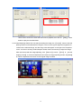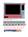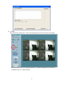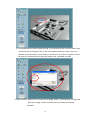
1
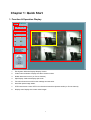
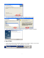
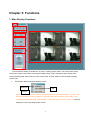
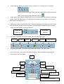
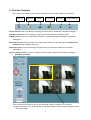
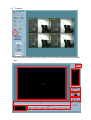
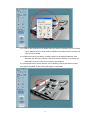
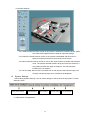
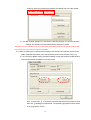
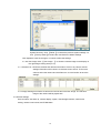
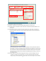
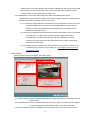
Vivotek ST2202 Software
User’s Manual
CONTENTS
CHAPTER 1: QUICK START ............................................................................................1
1. Function & Operation Display .................................................................................................................................. 1
2. Data Image Playback ................................................................................................................................................. 2
3. System Descriptions.................................................................................................................................................... 2
CHAPTER 2: ST2202 INSTALLATION .............................................................................3
1. Installation .................................................................................................................................................................. 3
2. Start ST2202................................................................................................................................................................ 4
CHAPTER 3: FUNCTIONS................................................................................................5
1. Main Display Functions ............................................................................................................................................. 5
2. Function Controls....................................................................................................................................................... 8
Chapter 1: Quick Start
1. Function & Operation Display
1
2
3
4
5
Focus camera
8
6
7
1.
Exit System/ Minimize Display/ Display Version.
2.
Video Camera Number: Display the video camera number.
3.
DI/DO status and control. (on Focus Camera)
4.
Split Display: Select the display split mode.
5.
Functions Control Area: All function-settings and execution.
6.
Hard disk space usage status.
7.
PTZ Control Area: Control PTZ in four directions/zoom/focus/preset recalls.(on Focus Camera)
8.
Display Area: Display the current video images.
1
2. Data Image Playback
2-9
2-1
2-5
2-2
2-3
2-4-1
2-4-3
2-4-2
2-6
2-7
2-8
2-1. Display current time.
2-2. Image zooms in or out.
2-3. Adjust the playing speed.
2-4. Search and select image for playing.
2-5. Display area.
2-6. Progress of playback.
2-7. Display the image recorded date and time.
2-8. Playback function controls.
2-9. Exit the playback function and return to the main display.
3. System Descriptions
ST2202 product series is one of the state-of-the-art scattering remote digital monitoring products in
the world. It adopts the advanced MPEG-4 image compression technology to accomplish the high-speed
image displaying and high-speed recording requirements. Furthermore, ST2202 also provides users and
mangers with the modern E-Map management module and an operation style, which resembling a
PC-Based DVR, to enjoy a high quality, convenient, and stable remote digital surveillance.
2
Chapter 2: ST2202 Installation
1. Installation
1. Before installing 【ST2202】, please make sure user computer has installed 『Direct X 8.0』 or above.
2. Click on 【Setup.exe】.
3. System will activate auto-installation, and the following display will appear. Click 【Next】.
Then click 【Yes】, and 【Next】.
Then click 【Yes】, and 【Next】.
3
4. The software’s installation program data will appear, click 【Next】 and then 【Yes】.
5. System will automatically complete the installation. Click 【Finish】 to complete the installation.
2. Start ST2202
1. System will automatically install 【ST2202】in Programs. Click on window’s 【Start】 menu and locate
【Vivotek Inc.】【Vivotek ST2202】 under 【Programs】. Click to start.
4
Chapter 3: Functions
1. Main Display Functions
1
2
3
4
5
8
6
7
The surveillance display is divided into 10 areas, including system status, PTZ control area, image
control area, speed control area, preset position display area, screen split display area, display area,
camera selecting area, alarm history, function control area, and exit system/ minimize display/ display
version area.
1.
Exit System/ Minimize Display/ Display Version
Minimize
Exit
Version
When user wished to exit the system, user would need left click here and select 【Exit】.If user
wished to operate the current system in conjunction with other functions of the system, user
could left click here and select 【Minimized】 to bring the system down to minimum. It will also
display the current operating system version.
5
2.
Camera Number: Display the camera number. A maximum of 4 cameras can be connected.
When a camera is returning images, the button of the camera number will be blue.
When server is disconnected, the button will turn.
3.
DI/DO Status: This is show the DI/DO status of the focus camera (the camera show in the display
area in status one camera view, or the left-top square camera). DO-Ctrl. Button can control the
DO status in the video Server.
4.
Split Display: Select the display split mode. The image displayed on the upper left corner is set as
the main display regardless of the split mode. If the camera did not install PTZ, the PTZ control
button would not appear on the right hand side.
5.
Screen Split
Screen Split
Selections
Selections
Function Control Area: All functions settings and executions of the system.
Record
Schedule
E-Map
Snap Shot
Playback
System Settings
6.
Hard disk space status: It shows the usage status and percents of hard disk space.
7.
PTZ Control Area: Control PTZ to turn in four directions. If the camera did not install PTZ, this
control button would not appear.
Up
機 Right
機 Left
機 Center
Dow
Zoom Out
Zoom In
Decrease focal distance
Increase focal distance
機 Auto Focus
Panning
Tilting Speed
6
Preset List from camera
Image Control Area: Image zoom in, out, and focus.
Speed Control: Control the PTZ turning speed.
Preset Position: Display the preset position of PTZ.
8.
Display Area: Display the currently video images. If no video camera were connected, nothing
would be showed. If the video signal were lost, it would appear “NO VIDEO SIGNAL”.
7
2. Function Controls
The function control area involves various operating functions as described in area 10 below.
Record
Schedule
E-Map
Snap Shot
Playback
System Settings
Record function: this is for starting or stopping manual recording. Details are described Paragraph 1.
Schedule function: this is for starting or stopping schedule to follow the schedule setting.
E-Map function: this is for arrange camera location in a background graphic. Details are described
Paragraph 3.
Snap Shot function: this is for capture on screen picture saves as a JPG file under the sub-directory
Snapshot of the installation directory.
Playback function: this is for searching and plays image recording files. Details are described
Paragraph 2
System setting function: this is for configure the whole system. Details are described Paragraph 4.
1.
Start/Stop Recording
Click on this function button to start or stop recording. When the system is not recording.
(1) When the system is only receiving and not recording images, a black border will appear around
the camera image.
8
(2) When the system is recording, a red border will appear around the camera image, and【Rec】will
also appear at the top of the System Status area.
9
2.
Playback
Recording must be stopped before play-backing. Click on this button to enter the following playback
page.
2-9
2-1
2-5
2-2
2-3
2-4-1
2-4-3
2-4-2
2-6
2-7
2-8
10
2-1. Display current time.
2-2. Playback image zooms in or out. Click 『+』 to zoom in and 『-』to zoom out.
2-3. Adjust the playing speed: The playing speed ranges from 1/8X to 8X. Click on the left button to
increase speed, and right button to reduce speed. The current select playing speed is displayed in
the middle. Select the playing speed before playing the recorded video. The speed cannot be
changed during the playing.
2-4. Search and select recorded video
ST2202 supports 2 types of video search mode: by channel and event
2-4-1 Channel Search Mode
2-4-1-1 Select single channel to play only one channel video or multiple channels button to select
desire cameras to play several channel videos simultaneously.
2-4-1-2 Select expected date and time frame. The left column is for date selection, and right column
for time selection. On the date section, a calendar will pop up for selecting the date. Click on
AM, PM, and the hr/min/sec sections respectively on the time section to mark up each
condition then uses the up/down button to adjust the time. The current date will be circled in
red and also be displayed in the left bottom of the calendar. Use the arrow button on the up
left right of the calendar for previous months and the right up arrow button for future months.
11
2-4-1-3 If the One Channel playing mode were selected, a corresponding camera must also be
selected for searching. If the Multiple Channel mode were selected, more than one camera
could be selected for simultaneous searching.
2-4-1-4 Select 『Round Clock』, 『Motion Detect』, separately or together for searching.
2-4-1-1
2-4-1-1
2-4-1-2
2-4-1-3
2-4-1-3
2-4-1-4
2-4-1-5 Click 【Ok】. System will list out all image data under the criteria for playing.
2-4-1-6 User can now use the functions in 4-8. Including viewing and checking the broadcasting
image.
2-4-2 Event Search Mode
This mode refers to the search and playback of the recorded video data by the individual event.
2-4-2-1 Select Event Search Mode.
2-4-2-2 Select the time period. The left column is for date selection, and right column for time
selection. On the date section, a same calendar as in the channel selection will pop up for
selecting the date. On the time section, click on AM, PM, and the hr/min/sec section, then
use the up/down button to adjust the time. Click on the 【Ok】 button in the middle. System
will list out all corresponding events.
12
Use mouse to click on the event that user wish to playback, then click on 【Play】 at the
bottom to play the recorded video.
2-4-3 Image Adjusting. Before user can start processing the image, the 【Pause】 button under the
playing mode must be selected first. Drag the cursors on the right to adjust the brightness or
contrast of the selected image, and the image value will appear on the right of the respective
cursor. Or click on the Gray Scale/ Sharpen/ Soften button continuously to adjust the image.
After user is done with the image adjusting, click 【Save As】 to save, 【Print】 to print the
image,【Cancel】 to cancel the adjustment and close the Image Adjusting window, or【Reset】
to undo the adjustment and return to the original image condition.
13
2-5. Display area: Playback the selected video
2-9
2-5
2-6
2-7
2-8
2-6. Progress of playback: Indicate the proportion of the played video
2-7. Display the video recorded date and time.
2-8. Video playing-controls. The operations are identical with the common VCR operations.
Rewind to Start
Fast Rewind
Stop
Play
Pause
Fast Forward
Forward to End
2-9. Exit the playback function and return to the main display.
2-10. Attention: When the database were damaged, which would resulted in the inability to find the video
data; or when user must reinstall the system due to problems in user’s computer, which would require
user to import the existing video data to the database of the new installed program, it would require to
execute 【Repair Database】 under the Programs directory of the start menu (this function is also
included in the installation CD). Please quit the ST2202 program while executing the repairing.
14
3.
E-Map
Also known as the “plane layout”. Click on the E-Map button to enter the electronic map display,
Move the mouse cursor on the E-Map and left click , a window will appear with two options of
【Background】 and 【Add Camera】.
15
3-1 Change Background: Select 【Background】, and a new background or the file location route
of the plane layout will appear. Click on the new background that user wish to use or the
filename of the plane layout, and click Open or double-click on the file to change the current
background. The background file types are limited to GIF, JPG, BMP, and PNG.
3-2 Add Camera: A maximum of 4 cameras can be added. Select 【Add Camera】 and open the
【Camera Config】 window to set the warning conditions and camera
directions.
16
3-2-1 Click on the pull-down menu beside Camera to add new cameras. Only one camera
can be added every time. User needs to repeat the procedure when more than one
camera must be added.
3-2-2 Select the warning conditions, including Image Lost and Motion Detected. Then
select the direction of the camera. Click OK to save the settings. The camera will
flash when an event occurs which meets the set conditions.
3-2-3 Camera Direction: Set the direction of the camera by clicking the direction button.
3-2-4 When completed, a new camera will appear on the E-Map.
17
3-3 Camera Settings.
3-3-1 Setting a Camera: Move mouse on left click the camera that required to be set. Select
one Camera and repeat the above steps to adjust the settings.
3-3-2 Remove a Camera: Move mouse on the camera to be deleted and left click on it.
Select a camera that wanted to removed and click remove.
3-3-3 Move a Camera: Move mouse on click on the camera. Select a camera that wanted to
move. The camera selected will flash. Drag and move the camera to a
new position and left click again to release it. The camera will be
located in the new position.
3-3-4 Show Image: Move mouse on and left click on the camera. Select Show Image. The
currently monitoring image of the camera will be displayed.
4.
System Settings
After entering System Settings, user can make changes to the functions of the system. Function
settings include:
Video Server Settings
General Settings
Video Settings
4-1 Video Server Configurations
18
Schedule Settings
User Management
4-1-1
4-1-2
4-1-3
4-1-8
4-1-4
4-1-5
4-1-6
4-1-7
4-1-1. Enter the name of server, user, password, host IP, HTTP and FTP ports.
4-1-2. Video Input. Maximum four video inputs are allowed.
4-1-3. Video Image Size. Three sizes are available in three sizes:
4-1-3-1 Half: NTSC: 176×120, PAL: 176×144
4-1-3-2 Standard: NTSC: 352×240, PAL: 352×288
4-1-3-3 Double: NTSC: 704×480, PAL: 704×576
4-1-4. Video Quality: Include medium, standard, good, detailed, and excellent.
4-1-5. Enable PTZ. Check this button to Enable PTZ. Check Custom PTZ to set PTZ port when
there is more than one com port in the computer. For advance settings, click Custom PTZ
Command to open the command setting window.
19
4-1-5
4-1-5-1 Movement Settings: Input command strings according to the PTZ operation menu
that corresponding to move PTZ up, down, left, right, focus, zoom in and zoom
out, etc.
4-1-5-1
4-1-5-2
4-1-5-2-1 Speed Settings: Set the panning speed and tilting speed. Input command strings
according to the PTZ operation menu that corresponding to turn PTZ in different
speeds.
4-1-5-2-2 Preset Position: Set the name of the preset position and the PTZ command
string. Click Save Preset to create a preset position. The preset position will
also list on the left column. To view a preset position setting that previously
created, move mouse on the preset and click Recall Preset. To clear the preset
20
positions, select the position that wished to be cleared and click Clear Preset.
4-1-5-2-1
4-1-5-2-2
4-1-5-3 After finished setting PTZ, click Save to save the changes, or Cancel to abort the
settings. The Custom PTZ Command window will then be closed.
Attention: Due to the difference in the model series provided by different companies, please refer
to the PTZ user manual for the respective models.
4-1-6 After completing the camera and PTZ settings, click Add to List to add the camera to the
system. Relevant information of the camera will be shown in the Camera List (6-1-7).
6-1-6-1 Firmware Update: Click【Update Firmware】to open the firmware update window.
The host information will display on the top section.
Click 【Select File…】 to browse the location and select the firmware file, and
then click 【Upload】to upload the file. The uploading progression will be shown
in the progression column.
21
System Recovery: Click 【Reset 】to restore the previous system settings. Or
click 【Factory Reset】to restore the manufacturer’s default settings.
Click Update to save the changes, or Cancel to abort the settings.
4-1-6-2 View Image: Click 【View Image…】 to show the camera image on the display on
the right image viewing area (6-1-8).
4-1-7 Camera List: List all the cameras and relevant information. Click on any camera, and its
settings information will be shown on relevant column above. To remove a
camera, select the camera and click Remove. Or click Confirm to save the
settings.
4-1-8 Image Viewing Area: Select a camera from the list and click View Image. The real-time
image of the camera will be played here.
4-2 General Settings
Set host name, auto start up, camera display, caption, data storage locations, web service
setting, camera scan interval, and E-Mail alarm.
22
4-2-1
4-2-2
4-2-3
4-2-5
4-2-4
4-2-7
4-2-6
4-2-1 Host Name: Set the name of the host.
4-2-2 Start Up: Include auto run when Windows starts and start in minimum form.
4-2-3 Camera Caption: Set whether to show camera ID, Camera ID and Camera Name, or not
showing any.
4-2-4 Data Storage Locations: Set the file location and path of the video data, and whether to
recycle the savings. Click New to open the data storage location window and decide the
storage path.
After selecting the path, click OK to complete the setting. The new path will be shown on
the list below. To remove a storage path, select the path and click Remove. If Recycle box
were checked, the system would automatically overwrite the data by first in first out order
when the HD is full. System will also indicate the available space remaining on the HD of
the storage location.
4-2-5 Camera Display: Set which camera image will be shown on the main display. The mail
camera is a camera on the top left screen. To move a particular camera to the main
display, simply click that particular camera number. The current image of such a camera
23
will be shown on the main display. If that camera contained PTZ, the control button would
also be shown on the left hand side. User can also click All Cameras ON to show all
camera images, or All Cameras OFF to show none.
4-2-6 E-Mail Alarm: To send the alarm image via E-Mail. The E-Mail’s SMTP server,
sender/receiver/copy receiver’s e-mails, and char-sets, subject, number of image attached,
and interval between sending the e-mail must be set.
4-2-7-1 Number of Image Attached: To decide how many image will be sent in one e-mail.
The more images send in one mail, the wider bandwidth and longer time are
required. It is recommended that only one image is sent with each e-mail to
shorten the transmission time.
4-2-7-2 Interval of Sending Email: Set the time interval for auto email re-send. The interval
can range from 1 to 99 seconds. If relevant action or alarm deactivating
procedure were not taken within this time interval, E-Mail alarm would be
continuously issuing at this interval until relevant action or alarm deactivating
procedure had been taken.
4-2-7-3 Multiple receivers are allowed in both receiver and copy receiver columns. Use “;”
to separate the receivers or copy receivers, e.g. [email protected];
[email protected]
4-3 Video Settings
Set the camera name, record mode, and motion detect.
4-3-2
4-3-1
4-3-4
4-3-3
4-3-5
4-3-1 Select Camera: Select a camera and its real-time image will be shown on the right below the
camera name.
4-3-2 Camera Name: Enter the camera name that wants to be shown. This name will also appear
on the main display and the playback video. It can also be left blank.
4-3-3 Record Control: Select a recording mode from monitor only, not record/ round-the-clock/
24
motion detect/ generic input trigger. If generic input trigger were selected,
the input type must be also chosen. After the setting is made, user can click
【Apply to All Cameras】 to apply the current setting to all cameras.
4-3-4 Image Display Area: Display the real-time image of the camera selected.
4-3-5 Motion Detect: Recording will start when motions are detected. The sensitivity level must be
set. Attention: that the function of motion detection only be enabling when the status
is in the recording state, the alarm mail is also in same situation.
4-3-5-1 Sensitivity Level: Drag the indicator between the sensitivity level from 1 to 10. The
sensitivity value will be shown on the left of the bar. The higher the
value is, the higher the sensitivity will be.
4-3-5-2 Click【Apply to All Cameras】to apply the motion detect settings to all cameras. When
an event which meets the motion detect conditions occurs, recording will be started,
and an M sign will appear on the upper-left corner of the display area.
4-4 Schedule Settings
Set the recording schedules and contents.
4-4-1
4-4-2
4-4-4
4-4-3
4-4-5
4-4-6
4-4-7
4-4-8
4-4-9
4-4-1 Time Period: Use mouse to click on the hour/minute to be adjusted for the starting or ending
time, then use the up/down button to adjust. Attention: the start time must be earlier than
25
the end time, or a
“double settings for the time period” message will appear on the
screen. Each day starts at 00:00 and ends at 23:59.
4-4-2 Job: Decide whether to enable recording or remote service or both. There are two recording
modes: round-the-clock and motion detect. Only one recording mode can be chosen.
4-4-3 Enable Camera: Select cameras for the schedule job.
4-4-4 Week Days: Select the scheduling days in a week.
4-4-5 Job Remark: Leave blank or add relevant descriptions regarding the scheduling.
4-4-6 When finished, click 【New Job】 to add the settings into the scheduling. The job information
will be shown in the table below schedule list.
4-4-7 Modify Job: Select and click a job that need to be modified, click 【Modify Job】, and follow the
above steps to edit the job contents.
4-4-8 Remove Job: Select and click a job that need to be removed from the schedule and click
【Remove Job】.
4-4-9 Click OK to save or Cancel to abort the settings when completing the settings and exit the
scheduling window.
4-5 User Management
Set, modify, or add user ID and password.
4-5-1 General root’s password setting. The password can be a combination of up to 12 English letters
and numerical numbers. The ID can be inputted in either capital or small letters, whereas the
password is case sensitive. The default name of the system root is 【Root】, and no password
is set. If no password were assigned for the root, or no user were added, there would be no
login window or password request when the start-up of the system. Simply click 【OK】 to
proceed. However, if password was assigned to the root, or one or more users were added, the
system would request to login and input of the correct user name and password to activate the
system.
26
4-5-1
4-5-2
4-5-3
4-5-4
4-5-5
4-5-2 User Information: Add the information of the new users.
4-5-2-1 User ID: Can be a combination of up to 16 characters of Chinese, English, and
numerical numbers. The User ID is case insensitive.
4-5-2-2 Password: Can be a combination of up to 16 characters of English and numerical
numbers. Password is case sensitive.
4-5-2-3 Description: Relevant information regarding the user can be added, e.g., “root” or
“guest.”
4-5-3 User Privilege: Select functions that allow the user to operate. Simply check the function boxes
to decide what function.
4-5-3-1 View: Include multi-camera view operation and camera map operation. Multiple
selections are allowed.
4-5-3-2 System Operation: Include scheduling, recording, and playback. Multiple selections are
allowed.
After relevant conditions are checked, click New to add a user. System will automatically add the
data to the User and List user information on the left column. Repeat the steps to add another
new user. User can begin to operate the system within the limitations assigned according to the
user ID and password.
4-5-4 Update: Select a current user from the list on the left column by clicking on it. The user
information will be shown in the right corresponding columns. Make any change on the relevant
column and click Update when finished.
4-5-5 Remove: To remove a user, select the user from the list and click Remove.
27