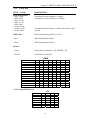
1
TAINET
JUPITER 2560
High-Speed Network Termination Unit
USER'S MANUAL
The Professional Partner
TAINET COMMUNICATION SYSTEM CORP.
Headquarters:
Beijing Branch:
No. 25, Alley 15, Lane 120, Sec. 1. 3F, A Building, 113 Zhi Chun Lu, HaiDian
Nei-Hu Rd,Taipei 114, Taiwan
District, Beijing, China
TEL: 886-2-26583000
Zip Code: 100086
FAX: 886-2-26583232
TEL: 86-10-62522081~87
http://www.tainet.net
FAX: 86- 10-62522077
V1.2
07008-00053
2004/03/24
CONTENTS
CHAPTER 1.
THE ISDN SERIES NTU (JUPITER) ..........................................1
1.1 Description.....................................................................................1
1.2 Technical Specifications ................................................................1
1.3 Ordering Information .....................................................................2
CHAPTER 2.
INSTALLATION ............................................................................3
2.1 Description.....................................................................................3
2.2 Unpacking......................................................................................3
2.3 Site Requirements ..........................................................................3
2.3.1 Site Selection........................................................................4
2.3.2 AC Electrical Outlet Connection .........................................4
2.4 Connecting with 2-wire Line .........................................................4
CHAPTER 3.
3.1
3.2
CHAPTER 4.
FRONT PANEL AND DIP SWITCH ...........................................5
The Front And Rear Panels............................................................5
Operating The JUPITER................................................................7
3.2.1 LED Indicator: 6 LED...........................................................7
3.2.2 Test Button ............................................................................7
3.2.3 Config NTU ..........................................................................7
3.2.4 Config DTE...........................................................................8
GENERAL INFORMATION AND FEATURES ........................9
4.1
Preview ..........................................................................................9
4.1.1 2W Unconditional Twisted Line ..........................................9
4.2 LT Mode VS. NT Mode.................................................................9
4.3 Synchronous VS. Asynchronous ...................................................9
CHAPTER 5.
5.1
5.2
5.3
5.4
5.5
CHAPTER 6.
6.1
MAINTENANCE ..........................................................................10
Description...................................................................................10
Instruments...................................................................................10
Periodic Maintenance...................................................................10
Troubleshooting ...........................................................................10
Return Procedure .........................................................................10
DTE INTERFACE DB-25 PIN ASSIGNMENT ........................11
DTE Interface DB-25 PIN Assignment .......................................11
-i-
Chapter 1 : THE ISDN Series NTU (JUPITER)
Chapter 1. THE ISDN Series NTU (JUPITER)
1.1
Description
•
TAINET JUPITER is high speed, synchronous and asynchronous, full duplex
Network Termination Unit (NTU). The JUPITER is a stand-alone type for desktop
use.
•
JUPITER fully complies with ANSI T1.601 using 2B1Q line coding and echo
cancellation technique for full duplex operation at synchronous 9600bps to
128Kbps or asynchronous 9.6,19.2 and 38.4Kbps transmission rate over a 2-wire
unconditioned unloaded twisted line.
•
JUPITER provides an operating range up to 5.5 Km over a 26-gauge wire or up to
7.8Km over a 24-gauge wire.
•
JUPITER provides internal or external clock flexible use in different applications
option in LT mode.
•
JUPITER also provides diagnostic capability including Analog loopback, Digital
loopback (Local and Remote) and BER TEST for troubleshooting both NTU and
the line.
•
JUPITER front panel LED indicators provide indication for TXD, RXD, DCD,
ERR, TST and PWR.
•
•
JUPITER front panel push button provides for TP, AL and DL/RDL.
1.2
Subrate (9.6, 19.2 and 38.4Kbps) complies with ITU-T X.50 division 3.
Technical Specifications
•
JUPITER NTU fully comply with ANSI T1.601.
•
DTE Speed
(1) Synchronous : 128K/64K/38.4K/19.2K/9600 bps
(2) Asynchronous : 38.4K/19.2K/9600bps
•
Line Requirement : 2 wire unconditioned unloaded twisted Line
•
Operating Range
(1) Up to 5.5 Km over 26 gauge wire
(2) Up to 7.8 Km over 24 gauge wire
•
Line Coding
: 2B1Q
•
Output Level
: 13 ~ 14dBm
-1-
Chapter 1 : THE ISDN Series NTU (JUPITER)
•
Line Impedance
: Balanced 135Ω
•
Line Interface
: RJ45 Connector
•
Equalization
: Adaptive Equalizer
•
Diagnostic Capability
(1) Analog Loopback
(2) Digital Loopback (Local or Remote)
(3) Remote Configuration
(4) BERT - Bit Error Rate Test with Test Pattern and Error Count
•
Timing
LT
: Internal or External clock
NT
: Loopback clock
•
Power Requirement
DC adaptor source : 12 VDC
Consumption
: Less than 2 Watts
•
Operating Temperature: 0 °C ~ 50 °C
Storage Temperature: -25 °C ~ 70 °C
Relative Humidity : up to 95 % (non-condensing)
•
Physical Size
(1) 183 W x 39.5 H x 218 D mm
•
DTE Interface
(1) EIA RS-232D, ITU-T V.28, 25pin D type, female
(2) EIA RS-530 25pin D type, female
(3) V.35 - 34 pin, female
(4) X.21/V.11 - 15pin, female
(5) G.703 64Kbps co-directional
1.3
Ordering Information
• JUPITER
High speed 128Kbps NTU
• Interface default
V.35, V.24/RS-232 ,RS-530, X.21/V.11
• Interface option
G.703 64Kbps co-directional
-2-
Chapter 2. INSTALLATION
Chapter 2. INSTALLATION
2.1
Description
This chapter provides the information needed to install the JUPITER NTU and to
ensure that it is working properly.
2.2
Unpacking
Save the carton and protective packing material in which your JUPITER NTU was
shipped; you might need them for repackaging if you have to store or ship the NTU in
the future. The following items are shipped with your JUPITER NTU:
•
•
•
•
•
One JUPITER NTU User's Manual.
One JUPITER NTU.
One power adapter.
One 2M modular telephone cable for connection to on RJ45 8-pin jack.
One 8-pin box for twisted line application.
Rough handling during shipping causes most early NTU failure; after you unpack the
NTU, check carefully for shipping damage. Contact the shipper if you notice any
damage.
Direct any additional questions about damaged or missing parts to the nearest sales
representative, or contact: [email protected] or #[email protected].
2.3
Site Requirements
The FCC requires telecommunications equipment to withstand electrical surges that
may result from lightning strikes; the TAINET Network Series NTU meet the
requirements set forth by the FCC. The following procedure outlines some common
practices that can minimize the risk of damage to computer equipment from electrical
surges.
1) Make sure the electrical service in your building is properly grounded as described
in article 250 of the National Electrical Code (NEC) handbook.
2) Verify that a good copper wire of the appropriate gauge, as described in Tables
250-94/95 of the NEC Handbook, is permanently connected between the electrical
service panel in the building and a proper grounding device such as:
) A ground rod buried outside the building at least 8 feet (2.44 meters) deep in the
earth.
) Several ground rods, connected together, buried outside the building at least 8
feet (2.44 meters) deep in the earth.
) A wire (see tables 250-94/95 of the NEC handbook for gauge) that surrounds
the outside of the building and is buried at least 2.5 feet (.76 meters) deep in the
-3-
Chapter 2. INSTALLATION
earth. Note: The three grounding devices described above should be firmly
placed in the earth. Soil conditions should not be dry where the device is buried.
) A metal water-supply pipe connected to the water main in the street or a metal
cased well. The water pipe used must not have plastic piping between the
ground connection and the water main (or the well). The connection should be
made where the pipe enters the building. The water meter must be shunted by a
copper strap.
3) If you are unsure whether the electrical service in your building is properly grounded,
have it examined by your municipal electrical inspector.
4) Install a surge protector between the NTU and Ground point. Any additional
computer equipment you have connected to the NTU (directly or through another
device), such as a terminal or printer should also be plugged into the same surge
protector. Make sure that the surge protector is properly rated for the devices you
have connected to it.
5) Call your telephone company and ask them if your telephone line is equipped with a
circuit surge protector.
6) If you are operating the NTU in an area where the risk of electrical surges form
lightning is high, disconnect the modem form the telephone line at the modem's rear
panel when it is not in use.
2.3.1
Site Selection
Locate the TAINET Network Series NTU no farther than 10 feet (3.8 meters) from your
data terminal equipment (DTE) and within 6 feet (1.83 meters) of a grounded AC outlet
furnishing the required power.
Install the NTU in a clean area that is free from environmental extremes. Allow at least
6 inch (15.24 cm) in front of the modem for access to the front panel, and at least 4-inch
(10.2 cm) in back for cable clearance. Position the modem so you can easily see the
front panel. Do not stack the another device on top of TAINET NTU.
2.3.2
AC Electrical Outlet Connection
Check the label on the bottom of the NTU for the unit's power requirements. Once you
are certain the power requirements specified on the label match those of your electrical
outlet, plug the power adapter and cable into the outlet.
2.4
Connecting with 2-wire Line
The pin layout of the connector for RJ45 operation is as follows, for 2-wire applications,
only pin 4, 5 are required:
PIN
1
2
3
4
5
6
7
8
NAME
NC
NC
NC
TXD/RXD
TXD/RXD
NC
NC
NC
Fig 2-1 : 2-wire Line Connection
-4-
Chapter 3. FRONT PANEL AND DIP SWITCH
Chapter 3. FRONT PANEL AND DIP SWITCH
3.1
The Front And Rear Panels
The front panel of TAINET JUPITER modem contains three push bottom (TP, AL and
DL/RDL Key) for direct operation, and 6 LED indicator lights providing a visual check
of the modem’s status, as illustrated blew.
Figure 3-1 TAINET JUPITER front panel
The rear panel of TAINET JUPITER NTU contains a 12V DC Power Inlet Connector, a
DB-25 connector (connected to DTE Equipment), and one RJ-45 telephone jack
(connected to 2-wire twisted line), as illustrated below. For more detailed description,
please refer to Chapter 2 "Installation" of this manual. In some applications may you
need DTE interface, such as RS-232, EIA-530, X.21, V.35, and G.703 64Kbps
co-directional interfaces. All of them are designed in our platform, and user can choose
one of them by order (which location refers to Figure 3-3.).
Figure 3-2 TAINET JUPITER rear panel
-5-
Chapter 3. FRONT PANEL AND DIP SWITCH
Figure 3-3 TAINET JUPITER Jumpers/Switches Location
-6-
Chapter 3. FRONT PANEL AND DIP SWITCH
3.2
Operating The JUPITER
3.2.1
LED Indicator: 6 LED
TXD
RXD
DCD
ERR
TST
PWR
3.2.2
-------
On for “0”, off for “1”, TXD signal present.
On for “0”, off for “1”, RXD signal present..
On for DCD signal present.
On for NTU is in the TP mode and it received the pattern error.
On for test mode active.
On for power supply OK.
Test Button
ITEM NAME
DESCRIPTION
Local analog loop test (ON/OFF). This test is normally
used to certify if the NTU is in normal operation
condition.
AL
☞ON
☞OFF
DL/RDL
☞ON
For remote digital loop test (ON/OFF). This test can
control remote NTU to perform digital loop for finding
out if the NTU and line of both ends are in normal
condition.
☞OFF
TP TYPE
Test patterns selection (CCITT V.52 Rec.)
☞ON
/"511" pattern.
☞OFF
/Turn off this function.
3.2.3
Config NTU
ITEM NAME
DESCRIPTION
☞LT-internal
/Select LT mode for activating request by sending 10k
Hz tone & internal clock source.
☞LT-external
/Select LT mode for activating request by sending 10k
Hz tone & external clock source.
☞NT-LBK
/Select NT mode for waiting 10kHz tone & loopback
clock source.
-7-
Chapter 3. FRONT PANEL AND DIP SWITCH
3.2.4
Config DTE
ITEM NAME
Data Rate/Format
☞Sync-128K
☞Sync-64K
☞Sync-38.4K
☞Sync-19.2K
☞Sync-9600
☞Async-38.4K
☞Async-19.2K
☞Async-9600
DESCRIPTION
Select data speed & format.
Synchronous from 9600bps to 128kbps.
Asynchronous from 9600bps to 38.4kbps.
RXD follow
RxD latch following the RxC or ExC.
☞RxC
/RxD latching follows RxC.
☞ExC
/RxD latching follows ExC.
Asynchronous data format is 1 start bit, 8 data bits, and 1
stop bit.
Button
☞Lock
Push button is unfruitful. (AL, DL/RDL, TP)
☞Unlock
Push button is effectual
SW5
1
1
0
1
0
1
9.6K
19.2K
38.4K
64K
128K
Sync
Async
LT INT
LT EXT
NT LBK
RxD follow RxC
RxD follow ExC
Button Lock
Button Unlock
2
0
1
1
0
0
3
0
0
0
1
1
4
5
6
0
1
X
0
0
1
7
8
0
1
0
1
0
1
3.2.5 Config DTE interface
S1
RS530A
RS530
X.21
V.35
RS449/V.36
RS232/V.28
NO Cable
1
0
0
0
0
0
0
0
-8-
2
0
1
0
1
0
1
0
3
1
0
0
1
1
0
0
4
1
1
1
0
0
0
0
Chapter 4 : GENERAL INFORMATION AND FEATURES
Chapter 4. GENERAL INFORMATION AND
FEATURES
4.1
Preview
In order to help you to get familiar with TAINET JUPITER NTU, this chapter
introduces you some common applications. For most applications, the materials of this
chapter will be enough.
4.1.1
2W Unconditional Twisted Line
There is nothing but line application in JUPITER series NTU. Not only do hardware
and recommendation limit, but also the environment and application field confine.
There are two-wire lined in NTU application.2W line achieves full duplex with only a
pair of lines.
4.2
LT Mode VS. NT Mode
You may find the information of LT/NT settings in the "LT/NT MODE" column of
"CONFIG NTU" MENU.
LT means NTU plays as a LT role running under internal clock or external clock option
and actively sending a 10kHz tone to activate NT. NT, under loopback clock, is
passively waiting an incoming 10kHz wake-up tone link up with LT. If two NTU units
desire to connect each other, undoubted fully, they need to setup one unit to LT, and the
other is NT.
4.3
Synchronous VS. Asynchronous
The data formats of both connecting NTUs must be exactly the same in order to
exchange data with each other. Choosing various data formats in two NTUs still could
connect each other, but they won‘t transmit or receive data exactly.
There are synchronous and asynchronous data formats. The common personal
computers and terminals are asynchronous. Whereas, the host computers and their
terminals are often synchronous.
For most multiplexes and routers, the connecting NTUs should be synchronous.
However, the user should know the type of the data terminal equipment (DTE) to get
proper operation.
-9-
Chapter 5. MAINTENANCE
Chapter 5. MAINTENANCE
5.1
Description
This chapter gives you the information of maintenance and the required instruments in
order to let you recover the troubles quickly.
5.2
Instruments
The only instrument you need is a multi-meter, due to the embedded digital and analog
test abilities.
5.3
Periodic Maintenance
For every three months, you should do the following jobs.
(a) Turn the power off, open top cap, clean the NTU, check the plugs, make sure all the
connectors are connected firmly.
(b) Be sure that the indicator functions are well.
5.4
Troubleshooting
Once the JUPITER failures, please check and record the indicators at the moment, and
then turn the power off. Consequently, make sure the IC's on printed circuit board are
firmly sited. Try to turn the power on again, if the trouble still exists, please follow the
procedures below.
1) Power Unit
• Make sure you get a proper power source. If no indicator is lighted, probably
the problem is the power unit.
• Check the power fuse; if it is broken, replace it.
2) Digital Interface
• Do the AL (local analog loopback) test, feed some data into the NTU and
check if they were returned.
• Please make sure the interface is connected firmly; also check if the cable is in
good condition.
5.5
Return Procedure
We suggest the individuals who hold a failed JUPITER would contact with your local
representative or distributor of Tainet, or just directly access our customer service
department as soon as possible in order not to cause catastrophe. You may locate the
contact address and phone number in the cover sheet of this manual.
-10-
Chapter 6. DTE Interface DB-25 PIN Assignment
Chapter 6. DTE Interface DB-25 PIN
Assignment
6.1
DTE Interface DB-25 PIN Assignment
ISO 2110 RS-232
PIN No.
EIA 530
V.35
X.21
(V.24)
Signal
Direction
Circuit Description
1 PG
PG
-
A
-
Frame Ground
2 TD
103
103a, BA (A)
P
103a
DCEDTE
Transmitted Data A
3 RD
104
104a, BB (A)
R
104a
DCEDTE
Received Data A
4 RTS
105
105a, CA (A)
C
105
DCEDTE
Request to Send A
5 CTS
106
106a, CB (A)
D
DCEDTE
Clear to Send A
6 DSR
107
107a, CC
E
DCEDTE
DCE Ready
7 SG
102
102, AB
B
102
8 DCD
109
109a, CF (A)
F
109a
9
115b, DD (B)
X
10
109b, CF (B)
11
113b, DA (B)
W
12
114b, DB (B)
AA
13
106b, CB (B)
14
103b, BA (B)
S
114a, DB (A)
Signal Common
DCEDTE
Received Line Signal
Detector A
DCEDTE
DCE Receiver Signal
Element Timing B
DCEDTE
Received Line Signal
Detector B
DCEDTE
DTE Transmit Signal
Element Timing B
DCEDTE
DCE Transmit Signal
Element Timing B
DCEDTE
Clear to Send B
103b
DCEDTE
Transmitted Data B
Y
114a
DCEDTE
DCE Transmit Signal
Element Timing A
104b, BB (B)
T
104b
DCEDTE
Received Data B
115a, DD (A)
V
DCEDTE
DCE Receiver Signal
Element Timing A
DCEDTE
Local Loop-back
DCEDTE
Request to Send B
108a, CD
DCEDTE
DTE Ready
21
RL
DCEDTE
Remote Loop-back
22
107b, CE
DCEDTE
Ring Indicator
23
108b, AC
DCEDTE
Signal Common
DCEDTE
DTE Transmit Signal
Element Timing A
DCEDTE
Test Mode
15 TC
114
16
17 RC
115
18
LL
19
105b, CA (B)
20 DTR
24 EXC
25
108
113
113a, DA (A)
109b
114b
105b
J
U
TM
-11-