1
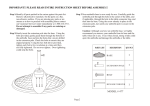
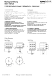
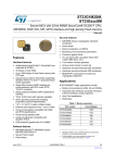
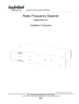
RFD-4000 Users Manual
1. Safety notes
1.1 Installation and startup
The rotary sensor is to be placed in service only by technical
personnel under observance of all relevant safety regulations.
Non-observance of the installation instructions will void any
warranty or liability claims.
All personal protection measures in case of a transducer defect
or failure must be taken before startup.
1.2 Electrical connections
The specified supply voltage is to be applied only at the terminals
provided. Non-observance of the pin configuration will result in
destruction of the device and loss of warranty.
2. RFD 4000 dimensions
1.3 Further Information
For further information relating to installation and properties of
this product and on available add-on items see also the
corresponding data sheet. These can be downloaded at
www.novotechnik.com under Resources
available also from your local representative.
1.4 Limitations for application
Our products are regularly not approved for aeronautic or aerospace
applications and are not allowed to be used in nuclear or military, in
particular ABC-relevant applications.
For more information see our Terms and Conditions
2. 1 Position markers
Z-RFC-P30 Recommended position marker for RFD 4000
Operating range:
A = 1.2 … 2.7mm
( single)
A = 0.75 … 2.25mm (redundant)
Z-RFC-P03
Z-RFC-P04
Z-RFC-P23
Further position markers pls. refer to separate data sheet
subject to change
Art.Nr.: 519708_00 - NTUS
page1
RFD-4000 Users Manual
4. Mounting examples sensor - position marker
3. Electrical data
Supply voltage
5 VDC ( 4.5...5.5 VDC)
Current draw
typ. 13 mA (8mA on request) per channel
Example A: mounting plate on inactive side
Wires
AWG 20 / 0.5mm2
Mounting plate
Sensor
3. 1 Electrical Connections
color
green
white
brown
single
supply
output
Ground
-
-
partly
redundant
supply
output 1
Ground
-
-
fully
redundant
supply 1
output 1
Ground 1 supply 2
red
black
NS
yellow
-
output 2
Example B: Measuring through mounting surface
Ground 2 output 2
Sensor
Non-magnetic
mounting plate
NS
3. 2 Output signal single
The operating range of the position marker must not be exceeded !
Example C: Position marker through plate
Sensor
mounting plate
NS
3. 3 Output signal redundant
Definition of center position :
When the marking of the position marker is pointing to the wire
outlet, the output signal is in center position.
5. Installation Instructions
Art.Nr.: 519708_00 - NTUS
•
Bare Magnets as position markers (Z-RFC-P03 or -P04 ) should be
mounted on non magnetic supports.
•
Basically, the sensor is sensitive against ferromagentic parts and DC
magnetic fields in close proximity.
To reduce influences from external magnetic fields and ferromagnetic
materials, the distance between position marker and sensor should be
kept small, refer to allowed operating ranges.
•
Only Novotechnik approved magnets may be used !
•
Using M4 screws, the max. tightening torque is 150 Ncm.
subject to change
page2