1
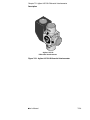
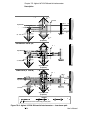
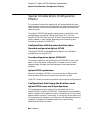
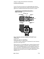
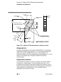
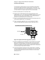
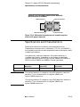
7G
Agilent 10715A Differential
Interferometer
Chapter 7G Agilent 10715A Differential Interferometer
Description
Description
The Agilent 10715A Differential Interferometer (see Figure 7G-1)
allows differential measurements to be made between two plane
mirrors — the reference plane mirror and the measurement plane
mirror. The reference mirror is supplied with the Agilent 10715A. The
measurement mirror must be a plane mirror such as the
Agilent 10724A Plane Mirror Reflector or other user-supplied plane
mirror.
The major benefit of the Agilent 10715A interferometer is that the
optical path is common to both the reference and the measurement
beams (see Figure 7G-2). This makes the Agilent 10715A extremely
tolerant of changes such as thermal expansion or changes in air
characteristics. When used in a positioning system, the small reference
mirror supplied can be mounted very close to the measurement mirror.
The advantages of the common beam path and the small reference
mirror combine to significantly reduce deadpath. Deadpath is the
optical path length difference between the reference and measurement
beams when the stage is at its initial “zero” position. Reducing
deadpath results in extremely high stability and resistance to spurious
changes in the optical path. Since the measurement beam travels twice
between the interferometer and the plane mirror, the resolution of the
measurement is twice that of a linear or single-beam interferometer.
A turned configuration (Agilent 10715A-001) is available to turn the
beam 90 degrees, thereby eliminating the need for a beam bender.
The orientation of the optics determines which frequency polarization
is in the measurement or reference path, thus affecting direction sense.
A differential measurement is one in which both the reference beam
and the measurement beam travel to external mirrors outside the
interferometer housing. This allows measurement of the relative
positions of the two external mirrors, either or both of which may be
moving. Viewed another way, this allows measuring the motion of one
reflector relative to a reference datum elsewhere in the machine,
external to the interferometer itself. This is unlike the typical
interferometer configuration because usually the reference beam path
length does not change; in differential configurations, it can.
For more information about differential measurements, see the
Chapter 3, “System Design Considerations,” in this manual.
7G-2
User’s Manual
Chapter 7G Agilent 10715A Differential Interferometer
Description
TIAL I N
T
E
R
10
METER
RO
FE
DI FFER
EN
71
5A
Agilent 10715A
Differential Interferometer
Figure 7G-1. Agilent 10715A Differential Interferometer
User’s Manual
7G-3
Chapter 7G Agilent 10715A Differential Interferometer
Description
MEASUREMENT PATH (ffA)
f ±2 ∆f
∆
λ/4 Plate
fA± ∆f
Aperture B
fA
fA±2 ∆f
Aperture A
fA±2 ∆f
fA±2 ∆f
fA ± ∆ f
Reference
Mirror
λ/4 Plate
f ± ∆f
Stage
Mirror
Agilent 10715A
(Top View)
REFERENCE PATH (fB)
λ/4 Plate
Aperture B
Aperture A
λ/4 Plate
Mirror
Stage
Mirror
Agilent 10715A
(Top View)
COMPOSITE (ffA and fB)
fA±2 ∆f
λ/4 Plate
f
fA
fA±2 ∆f
∆
Aperture B
Aperture
A±2 ∆ f
fA ± ∆ f
fA±2 ∆f
∆
λ/4 Plate
Mirror
A± ∆f
Stage
Mirror
Agilent 10715A
(Top View)
LEGEND
= fA
=
= fB
= fA and fB
Rounded corners are used to help you trace paths.
Figure 7G-2. Agilent 10715A Differential Interferometer — laser beam path
7G-4
User’s Manual
Chapter 7G Agilent 10715A Differential Interferometer
Special Considerations (Configuration Effects)
Special Considerations (Configuration
Effects)
For purposes of convention, aperture B will be considered the input
aperture when referring to all configurations. Note that the choice of
input aperture is one of the configuration variables that affects the
direction sense.
The Agilent 10715A Differential Interferometer is available in two
configurations; the Agilent 10715A (see Figure 7G-3) and the
Agilent 10715A-001 (see Figure 7G-4). Both have the same direction
sense; however, it may change, depending on the mounting and
orientation as shown in Table 7G-1.
Configurations with the same direction sense
Standard configuration Agilent 10715A
The Agilent 10715A is assembled and shipped in the “Standard”
configuration (see Figure 7G-3).
Turned configuration Agilent 10715A-001
The primary reason for using the Agilent 10715A-001 is to turn the
beam. In the “Standard” configuration, the beam is not turned (it
passes straight through the interferometer to the measurement
reflector).
Agilent 10715A upside down
Mounting the Agilent 10715A in this manner has no effect on the
direction sense, assuming the same input aperture is used.
Table 7G-1 shows the direction sense for various optical configurations.
Configurations that change the direction sense
Agilent 10715A Input and Output Apertures
The laser beam may enter either of the two apertures on the
Agilent 10715A or Agilent 10715A-001. These apertures are labeled A
and B. If aperture A is used as the input, then aperture B is the output
aperture and vice-versa. Functionally, it is arbitrary which aperture is
the input aperture. However, the choice of A or B does determine which
frequency is passed to the measurement mirror and thereby
determines the direction sense.
User’s Manual
7G-5
Chapter 7G Agilent 10715A Differential Interferometer
Special Considerations (Configuration Effects)
AGILENT 10715A STANDARD CONFIGURATION
Adapter
Plane Mirror
Converter
A
TI
L I NTERF
DI FFERE
N
B
ETER
OM
ER
A
10715A
Figure 7G-3. Agilent 10715A Standard Configuration
AGILENT 10715A-001 TURNED CONFIGURATION
Adapter
A
TI
L I NTERF
DI FFERE
B
ETER
OM
ER
A
N
Plane Mirror
Converter
10715A
Figure 7G-4. Agilent 10715A-001 Turned Configuration
7G-6
User’s Manual
Chapter 7G Agilent 10715A Differential Interferometer
Mounting
Agilent 10715A orientation (horizontal or vertical)
The Agilent 10715A may be mounted on a horizontal surface or a
vertical surface. The direction sense will be different for each
orientation.
If any two of the conditions described above, including the laser head
orientation, are changed there is no net change in the direction sense.
Table 7G-1. Agilent 10715A direction sense
Laser Head
Laser Head Orientation
Horizontal or Rolled 90°
About Beam
Agilent 10715A
Input Aperture
A or B
Agilent 10715A
Orientation
Horizontal or
Vertical
F1 Path
Horizontal
Ref
Vertical
Meas
B
Horizontal
Meas
A
Horizontal
Meas
Vertical
Ref
Horizontal
Ref
Vertical
Meas
A
Horizontal
Agilent 5517A/B/C/D
F1 Horizontal
F2 Vertical
Rotated 90°
B
Mounting
Adjustable mounts
The Agilent 10711A Adjustable Mount provides a convenient means of
mounting, aligning, and securely locking the Agilent 10715A
interferometer in position. Since the mount allows some tilt and yaw
adjustment, the need for custom fixturing is minimized. The mount
allows the interferometer to be rotated about its centerline, simplifying
installation.
Fasteners
The Agilent 10715A interferometer is supplied with English mounting
hardware, which is required to fasten it to its adjustable mount.
User’s Manual
7G-7
Chapter 7G Agilent 10715A Differential Interferometer
Installation and Alignment
Installation and Alignment
The Agilent 10715A Differential Interferometer alignment procedure
has more steps than those for other Agilent interferometers because its
reference mirror must also be aligned.
Before discussing the alignment procedure for this interferometer,
details on beam locations and reference mirror mounting will be
covered.
Configurations
Two configurations are available for the Agilent 10715A Differential
Interferometer, allowing flexibility in optical layout of a measurement
system. They are:
•
Standard
•
Turned (10715-001)
Figure 7G-5 shows the location of the measurement and reference
beams for the standard configuration using input aperture B. The
beams are switched if input aperture A is used.
STANDARD AGILENT 10715A BEAM LOCATIONS
Adapter
L I NTERF
DI FFERE
A
TI
Reference
Beam
ETER
OM
ER
N
Measurement
Beam
10715A
Reference
Beam
Measurement
Beam
12.7 mm
(0.5)
Figure 7G-5. Beam locations for standard Agilent 10715A Differential Interferometer
7G-8
User’s Manual
Chapter 7G Agilent 10715A Differential Interferometer
Installation and Alignment
Figure 7G-6 shows the location of the measurement and reference
beams for the turned configuration (Agilent 10715A-001) using input
aperture B. The beams are switched if input aperture A is used.
AGILENT 10715A-001 TURNED CONFIGURATION
BEAM LOCATIONS
8.1 mm
(0.32)
Measurement
Beam
Reference
Beam
12.7 mm (0.5)
Measurement
Beam
L I NTERF
DI FFERE
A
TI
ETER
OM
ER
N
Reference
Beam
10715A
Figure 7G-6. Beam locations for Agilent 10715A-001 Turned
Configuration
Reference mirror mounting
The Agilent 10715A interferometer is supplied with a small reference
plane mirror (see Figure 7G-7).
Mount the mirror on an adjustable mount so proper alignment can be
obtained. When alignment is achieved, rigidly fix the position of the
mirror. The recommended method is to use an adhesive to attach the
mirror to the mount. The adhesive should not induce stress into the
glass during curing. Place the mirror-and-mount assembly as close as
possible to the near end of travel of the stage to reduce potential
deadpath errors.
User’s Manual
7G-9
Chapter 7G Agilent 10715A Differential Interferometer
Installation and Alignment
REFERENCE MIRROR FOR AGILENT 10715A
(2X) 3.6 mm R
(0.14)
8.1 mm
(0.32)
(2X) 3.2 mm R
(0.13)
6.3 mm
(0.25)
22.9 mm
(0.90)
Either Both Reference
or Measurement Beams
12.7 mm
(0.50)
5.1 mm
(0.20)
57 o 23'
Either Both Reference
or Measurement Beams
3.4 mm
(0.13)
5.1 mm
(0.20)
9.9 mm
(0.39)
18.3 mm
(0.72)
Agilent Part Number: 10715-20205
Weight: 3.2 grams (0.11 ounce)
Figure 7G-7. Agilent 10715A Interferometer (reference mirror)
Alignment aid
Alignment Aid (Agilent Part Number 10706-60001) is included with
the Agilent 10715A interferometer. This is the same alignment aid
used on the Agilent 10706A Plane Mirror Interferometer. For
information about use of this alignment aid, see subchapter 7C in this
manual, which deals with the Agilent 10706A Plane Mirror
Interferometer.
Alignment procedure
This alignment procedure is similar to that for the Agilent 10706A
Plane Mirror Interferometer. The main difference is that in this
procedure the laser beam must pass through small apertures, which
requires fairly precise alignment to avoid clipping part of the beam. It
is assumed that the measurement mirror has been aligned
perpendicular to the axis of travel.
7G-10
User’s Manual
Chapter 7G Agilent 10715A Differential Interferometer
Installation and Alignment
The alignment procedure below is for the “Standard Configuration”,
with the laser beam entering the interferometer in aperture B. The
alignment procedure for the “Turned Configuration” is similar, except
it is more sensitive to angular alignment of the interferometer.
1 Select the small aperture on the laser head.
2 Roughly align the laser beam for each axis perpendicular to the
measurement mirror. This is done by autoreflecting off this mirror and
adjusting the laser head or beam bender until the reflected beam is
centered in the small aperture on the laser head.
3 Move the interferometer side-to-side so that the laser beam enters the
input aperture (aperture B in this example).
4 Place a rectangular gage block over the input aperture so that it
reflects the laser beam back toward the laser. (See Figure 7G-8.)
L I NTERF
DI FFERE
A
TI
ETER
OM
ER
Laser Beam
N
AGILENT 10715A WITH GAGE BLOCK
10715A
Gage Block
Figure 7G-8. Agilent 10715A with gage block in position
5 Adjust the differential interferometer in pitch and yaw until the laser
beam is autoreflected back into the laser head. This insures proper
alignment. It may be necessary to move the interferometer again to
center the laser beam on the input aperture (aperture B). Use a piece of
translucent tape to help observe the beam.
6 Once the autoreflection alignment of the interferometer is complete,
remove the gage block and select the large aperture on the laser head.
Two parallel unclipped beams should now leave the interferometer.
(See Figure 7G-9.)
User’s Manual
7G-11
Chapter 7G Agilent 10715A Differential Interferometer
Installation and Alignment
Note that the autoreflection procedure above is used only to reduce
clipping, and is not as critical as the autoreflection procedure used to
reduce cosine error. As long as the two beams are not clipped, the
alignment of the interferometer is adequate.
One of the two beams will be directed to the measurement mirror; the
other will be directed to the stationary reference mirror. Which beam
goes to which mirror affects only the direction sense (discussed in the
“Effect of Optics on Measurement Direction Sense” section of
Chapter 3, “System Design Considerations,” of this manual).
Since it is important that the beam going to the measurement mirror
be properly aligned to avoid cosine error, this alignment will be
performed first. Alignment is iterative because both the incoming beam
and the interferometer require adjustment.
AGILENT 10715A VIEWED FROM PLANE MIRROR
Reference Beam
Measurement Beam
Figure 7G-9. Differential interferometer as viewed from plane mirrors
7 Place the alignment aid over the output aperture (plane mirror
converter) of the Differential Interferometer such that the beam going
to the measurement mirror (which becomes the measurement beam)
passes through the alignment target. (See Figure 7G-10.)
7G-12
User’s Manual
Chapter 7G Agilent 10715A Differential Interferometer
Installation and Alignment
AGILENT 10715A WITH ALIGNMENT AID
RE
AF MOV
TE
R
ET
AL ARG
Ag
IG
ile
NIN ET
nt
Te
G
ch
no
log
ies
Alignment Aid
Part Number 10706-60001
Measurement Beam
Figure 7G-10. Agilent 10715A with alignment aid attached over
measurement beam
8 This beam should clear the reference mirror and strike the
measurement mirror. Select the small aperture on the front turret of
the laser head. Adjust the laser beam until the beam is autoreflected
back through the small aperture of the laser head. This ensures that
the beam is perpendicular to the measurement mirror. This step
requires pitching and yawing the laser head, beam benders, or beam
splitters depending on optical layout. Steps 4 and 5 should be
performed after each adjustment to prevent the interferometer from
clipping the laser beam.
9 Remove the alignment aid. Laser (measurement) beams should now
exit the interferometer aperture in diametrically opposite positions.
(See Figure 7G-11.)
AGILENT 10715A VIEWED FROM PLANE MIRRORS
WITH MEASUREMENT BEAMS ALIGNED
Measurement Beams
Figure 7G-11. Differential interferometer as viewed from plane
mirrors with measurement beams aligned
User’s Manual
7G-13
Chapter 7G Agilent 10715A Differential Interferometer
Installation and Alignment
10 Switch to the large aperture on the laser head.
11 Check to ensure that both measurement beams pass clear of the
stationary reference mirror. If necessary, move the reference mirror
until both measurement beams pass clear. The return beam should
now pass unclipped to the receiver.
12 Replace the alignment aid over the output aperture of the differential
interferometer such that the beam going to the reference mirror (which
becomes the reference beam) passes through the alignment aid. (See
Figure 7G-12.)
The full reference beam should strike the reference mirror. Select the
small aperture on the laser head. If the reference mirror is parallel to
the movable mirror, the reference beam will now be reflected back to
the small aperture on the laser head. If not, the reference mirror must
be adjusted in pitch and yaw until the reference beam is centered on
the small aperture.
13 Remove the alignment aid. The measurement beam and the reference
beam should now exit the interferometer aperture in diametrically
opposite positions. Switch the laser head to its large aperture. (See
Figure 7G-13.)
The measurement beam and the reference beam should pass unclipped
to the receiver. Verify this by checking that these beams are centered
in the output aperture (aperture A). Use a piece of translucent tape to
help observe the laser beam.
AGILENT 10715A WITH ALIGNMENT AID
Alignment Aid
Part Number 10706-60001
ET
RG
TA ING
IGN
ies
log
hno
Tec
t
n
gile
VE
L
MO
RE ER A
T
AF
A
Reference Beam
Figure 7G-12. Alignment aid attached over reference beam
7G-14
User’s Manual
Chapter 7G Agilent 10715A Differential Interferometer
Specifications and Characteristics
AGILENT 10715A VIEWED FROM PLANE MIRRORS
WITH PROPER ALIGNMENT
Reference Beam
Measurement Beam
Measurement Beam
Reference Beam
Figure 7G-13. Differential interferometer as viewed from plane
mirrors with proper alignment
Specifications and Characteristics
Specifications describe the device’s warranted performance.
Supplemental characteristics (indicated by TYPICAL or NOMINAL)
are intended to provide non-warranted performance information useful
in applying the device.
Using electronic resolution extension, the system resolution is
increased significantly. Depending on the system, an additional
resolution extension factor of 32 (for Agilent 10885A and 10895A) or
256 (for Agilent 10897B and 10898A) is usually available.
Interferometer
Fundamental Optical
Resolution
System Resolution 1
(see NOTE)
System Resolution 2
(see NOTE)
Agilent 10715A
λ /4 (158.2 nm, 6.2 µin)
λ /128 (5.0 nm, 0.2 µin)
λ /1024 (0.62 nm, 0.024 µin)
NOTE
The system resolution 1 is based on using 32X electronic resolution
extension. This is available with the Agilent 10885A and
Agilent 10895A electronics.
The system resolution 2 is based on using 256X electronic resolution
extension. This is available with the Agilent 10897B and
Agilent 10898A electronics.
User’s Manual
7G-15
Chapter 7G Agilent 10715A Differential Interferometer
Specifications and Characteristics
Agilent 10715A Differential Interferometer (and
10715A-001 Turned Configuration) Specifications
Weight: 504 grams (1.1 pounds)
Dimensions: see figure below
Materials Used:
Housing: Stainless Steel and Aluminum
NOTE: Flatness deviations will appear as measurement errors
when the mirror is translated across the beam. Mount should be
kinematic so as not to bend mirror. If accuracy requirements
demand it, mirror flatness might be calibrated (scanned and
Optics: Optical Grade Class
stored in the system controller) to be used as a correction
Adhesives: Vacuum Grade
factor.
Optical Efficiency: (including a 98% efficient plane mirror reflector and MEASUREMENT OR REFERENCE MIRROR ALIGNMENT
the Reference Mirror)
REQUIREMENTS VS DISTANCE:
Typical: 36%
Maximum Angular Misalignment (pitch and yaw):
Depends on distance between interferometer and plane mirror.
Worst Case: 25%
Fundamental Optical Resolution: λ /4
Non-linearity Error: <2.2 nm (0.09 µin)
MEASUREMENT PLANE MIRROR RECOMMENDATIONS
Reflectance: 98% for 633 nanometers at normal incidence
Typical values are:
± 2.5 arc-minutes for 152 mm (6 inches)
± 1.3 arc-minutes for 305 mm (12 inches)
± 0.7 arc-minute for 508 mm (20 inches)
Optical Surface Quality: 60–40 per Mil-0-13830
Thermal Drift: <0.002 micron/°C (0.08 µ/°C) typical
Flatness: Depending on the application and accuracy requirements of Fundamental Optical Resolution: λ /4
the application, mirror flatness may range from λ /4 to λ /20; i.e., 0.16 to Non-linearity Error: <3.5 nm (0.14 µinch)
0.03 µmeters (6 to 1.2 µinches).
90.2 mm
(3.55)
(See Note)
12.7 mm
(0.50)
SYM @ Center Line
12.7 mm
(0.50)
38.9 mm
(1.53)
DIFFERE
N
B
INTERF
AL
E
TI
E
MET R
RO
A
85.9 mm
(3.38)
32.0 mm
(1.26)
10715A
8.1 mm
(0.32)
23.9 mm
(0.94)
6-32 UNC (4 Places)
Thru Clearance
For No. 4 or 25 mm
28.4 mm
(1.12)
32.0 mm
(1.26)
To Mirrors
From Laser
12.7 mm
(0.50)
38.1 mm
(1.50)
28.4 mm
(1.12)
Note
To Receiver
14.0 mm
m
(0.55)
For 10715A-001, this dimension
is 100.1mm (3.94).
Agilent 10715A Differential Interferometer (and Agilent 10715A-001
Turned Configuration) — dimensions
7G-16
User’s Manual
Product specifications and descriptions in this
document subject to change without notice.
Copyright (C) 2002 Agilent Technologies
Printed in U.S.A. 07/02
This is a chapter from the manual titled:
Laser and Optics User's Manual
For complete manual, order:
Paper version: p/n 05517-90045
CD version: p/n 05517-90063
This chapter is p/n 05517-90114