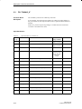
1
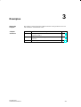
Contents
SIMATIC
PID Self-Tuner
User Manual
This manual is part of the software
package with order number:
6ES7860-4AA00-0YX0
Getting Started
1
Description of the Function
Blocks
2
Examples
3
Technical Specifications
4
Safety Guidelines
!
!
!
This manual contains notices which you should observe to ensure your own personal safety,
as well as to protect the product and connected equipment. These notices are highlighted in
the manual by a warning triangle and are marked as follows according to the level of danger:
Danger
indicates that death, severe personal injury or substantial property damage will result if
proper precautions are not taken.
Warning
indicates that death, severe personal injury or substantial property damage can result if
proper precautions are not taken.
Caution
indicates that minor personal injury or property damage can result if proper precautions are
not taken.
Note
draws your attention to particularly important information on the product, handling the
product, or to a particular part of the documentation.
Qualified Personnel
Only qualified personnel should be allowed to install and work on this equipment.
Qualified persons are defined as persons who are authorized to commission, to ground, and
to tag circuits, equipment, and systems in accordance with established safety practices and
standards.
Correct Usage
Note the following:
!
Warning
This device and its components may only be used for the applications described in the
catalog or the technical description, and only in connection with devices or components
from other manufacturers which have been approved or recommended by Siemens.
This product can only function correctly and safely if it is transported, stored, set up, and
installed correctly, and operated and maintained as recommended.
Trademarks
SIMATIC, SIMATIC NET and SIMATIC HMI are registered trademarks of
SIEMENS AG.
Third parties using for their own purposes any other names in this document which refer to
trademarks might infringe upon the rights of the trademark owners.
Copyright Siemens AG 1997 All rights reserved
Disclaimer of Liability
The reproduction, transmission or use of this document or its
contents is not permitted without express written authority.
Offenders will be liable for damages. All rights, including rights
created by patent grant or registration of a utility model or design, are
reserved.
We have checked the contents of this manual for agreement with the
hardware and software described. Since deviations cannot be
precluded entirely, we cannot guarantee full agreement. However,
the data in this manual are reviewed regularly and any necessary
corrections included in subsequent editions. Suggestions for
improvement are welcomed.
Siemens AG
Bereich Automatisierungs- und Antriebstechniktechnik
Geschaeftsgebiet Industrie-Automatisierungssysteme
Postfach 4848, D- 90327 Nuernberg
Siemens AG 1997
Subject to change.
Siemens Aktiengesellschaft
C79000-G7076-C825
Contents
1
Getting Started . . . . . . . . . . . . . . . . . . . . . . . . . . . . . . . . . . . . . . . . . . . . . . . . . . . . . . . . . .
1-1
2
Description of the Function Blocks . . . . . . . . . . . . . . . . . . . . . . . . . . . . . . . . . . . . . . .
2-1
2.1
Area of Application . . . . . . . . . . . . . . . . . . . . . . . . . . . . . . . . . . . . . . . . . . . . . . .
2-2
2.2
FB “TUNING_C” . . . . . . . . . . . . . . . . . . . . . . . . . . . . . . . . . . . . . . . . . . . . . . . . .
2-6
2.3
FB “TUNING_S” . . . . . . . . . . . . . . . . . . . . . . . . . . . . . . . . . . . . . . . . . . . . . . . . .
2-14
Examples . . . . . . . . . . . . . . . . . . . . . . . . . . . . . . . . . . . . . . . . . . . . . . . . . . . . . . . . . . . . . . .
3-1
3.1
3.1.1
3.1.2
3.1.3
Working Examples for the “PID Control” Controller Integrated in STEP 7
Example 1: Initial Tuning of a Step Controller . . . . . . . . . . . . . . . . . . . . . . . .
Example 2: Initial Tuning of a Continuous Controller . . . . . . . . . . . . . . . . . .
Example 3: Initial Tuning of a Continuous Controller with Pulse Generator
3-2
3-2
3-4
3-6
3.2
3.2.1
3.2.2
3.2.3
3.2.4
Examples of Interconnecting Blocks with Further PID Controllers . . . . . . .
The “PID Control” Control Package Integrated in STEP 7 . . . . . . . . . . . . . .
“Standard PID Control” optional package . . . . . . . . . . . . . . . . . . . . . . . . . . . .
“Modular PID Control” Optional Package . . . . . . . . . . . . . . . . . . . . . . . . . . . .
FM 355 and FM 455 Controller Modules . . . . . . . . . . . . . . . . . . . . . . . . . . . .
3-8
3-8
3-9
3-11
3-14
3.3
Pure Cooling Control . . . . . . . . . . . . . . . . . . . . . . . . . . . . . . . . . . . . . . . . . . . . .
3-17
Technical Specifications . . . . . . . . . . . . . . . . . . . . . . . . . . . . . . . . . . . . . . . . . . . . . . . . .
4-1
3
4
PID Self-Tuner
C79000-G7076-C825-01
i
ii
PID Self-Tuner
C79000-G7076-C825-01
Getting Started
Aims
1
You want to control a temperature process that is driven by a semiconductor
relay using SIMATIC S7 PID Control and want the PID controller parameters
to be set online using the PID Self–Tuner.
To complete your application quickly, work through the steps outlined below
one after the other.
Requirements
The following requirements must be met:
You have an S7-300/400 station consisting of a power supply, a CPU, an
analog input module and a digital output module.
STEP 7 ( V3.1) is installed on your programming device.
The programming device is connected to the CPU.
Installing the PID
Self–Tuner on the
Programming
Device
Follow the steps outlined below:
Make a copy of your original diskettes.
Using your copy, install the software by starting the SETUP.EXE
installation program on diskette 1.
Creating a New
Project
Create a new project in the SIMATIC manager and insert a SIMATIC 300 or
a SIMATIC 400 station. You can then configure your station with the
appropriate modules in Hardware Configuration. At this point, you can
already set the cycle time for OB35 to 20 ms.
Copying a Working
Example to your
Project
n the SIMATIC manager, you can now copy the working example 3 “initial
tuning of a continuous controller with pulse generator” into your project from
TunPIDEx. Download your project to the CPU and familiarize yourself with
the example as described in Section 3.1.3.
Wiring the Process
for the
Manipulated and
Process Variables
Wire the sensor that measures the process variable to be controlled to the
analog input module. In your project, you must assign the appropriate
peripheral input word PIWx to the PV_PER input for the CONT_C call. The
PVPER_ON parameter must be set to TRUE. Now check your process value
in the curve recorder or in a VAT. You can normalize the process variable
with the parameters PV_FAC and PV_OFF.
PID Self-Tuner
C79000-G7076-C825-01
1-1
Getting Started
Wire the digital output module to the semiconductor relay that controls the
heating. In your project you must assign the appropriate output bit (Qx.y) to
the QPOS_P output for the PULSEGEN call in OB35. Check the heating of
the process in the manual mode. In the variable declaration table VAT
TUNING_C you can set MAN_ON to TRUE and set individual manipulated
values in MAN.
Process Analysis
.Apply a manipulated value jump for example from 0% to 30% to the heating
and record the step response of the process variable with the curve recorder
of PID Control. Check the operating range of the PID Self–Tuner. This is
described in Section 2.1.
Startup/Test
Allow the process to cool to ambient temperature. Switch the parameter
“DI_TUNING_C”.TUN_ON to TRUE in the variable declaration table VAT
TUNING_C. Wait until the process variable is more or less constant and then
apply a setpoint jump with the parameter “DI_CONT_C”.SP_INT.
After the process settles to the operating point, you can test the control
response of the initial controller settings based on small setpoint jumps
around the operating point or by applying disturbances.
1-2
PID Self-Tuner
C79000-G7076-C825-01
Description of the Function Blocks
What Does this
Chapter Describe?
Chapter
Overview
PID Self-Tuner
C79000-G7076-C825-01
2
This chapter contains a detailed description of the function blocks of the PID
Self-Tuner.
Section
Description
Page
2.1
Area of Application
2-2
2.2
FB “Tuning_C”
2-6
2.3
FB “Tuning_S“
2-14
2-1
Description of the Function Blocks
2.1
Area of Application
Advantages and
Areas of
Application
With the PID Self-Tuner, you can trim the following SIMATIC S7 and
SIMATIC C7 PID controllers:
PID Control (integrated in STEP 7, FB “CONT_C” and FB “CONT_S”)
Standard PID Control (FB “PID_C” and FB “PID_S”)
Modular PID Control (FB “PID”, FB “LMNGEN_C” and “LMNGEN_S”)
FM 355 and FM 455 controller modules (FB “PID_CS”)
These then become self-tuning PID controllers. PID self-tuners are
particularly useful for the following:
Temperature controls (main application)
Level controls
Flow controls.
In flow controls, a distinction must be made between situations in which only
the control valve itself must be controlled and situations in which the control
valve regulates a process involving a time lag. The PID Self-Tuner cannot be
used for simple control of a valve (see also “Processes with a Control Valve
with Integral Action”).
Process
Requirements
The process must meet the following requirements:
Stable, time lag, asymptotic transient response
Time lags not too large
Adequate linear response with an adequately large operating range
Process controllable with a monopolar actuating signal 0 to 100%
Little disturbance in temperature processes
Adequate quality of the measured signals in the sense of an adequately
high signal-to-noise ratio.
Process gain not too high
Transient
Response
2-2
The process must have a stable, asymptotic transient response with time lag.
After a step change in the manipulated variable (LMN) the process variable
must change to a steady state as shown in Figure 2-1. This therefore excludes
processes that have an oscillating response without control and processes that
are not self-regulating (integrator in the process).
PID Self-Tuner
C79000-G7076-C825-01
Description of the Function Blocks
Process response to
a manipulated value step change
Point of inflection
ta
tu
t
Figure 2-1 Process Response
Time Lags
The process must not involve large time lags.
The range of application can be specified based on the ratio of the delay time
tu and settling time ta. The time lag includes any existing dead time. The
initial setting or adaptation is designed for the following range:
tu <
1
ta
10
Most temperature processes are within this range and both a PI or a PID
controller can be designed for this range.
For the following range:
1
1
ta < tu < ta
10
3
The initial setting of a usable PID controller is still possible. With such a
range, the duration of the learning phase can be significantly increased and
overshoot can occur during the learning phase particularly with combinations
of high process gain and small test step changes.
Linearity and
Operating Range
The process must have an adequately linear response over an adequately
large operating range.
This means that both during identification and during normal controlled
operation, non-linear effects within the operating range can be ignored. It is,
however possible to re-identify the process when the operating point changes
if the adaptive process is repeated in the close vicinity of the new operating
point and providing that the non-linearity does not occur during the
adaptation.
PID Self-Tuner
C79000-G7076-C825-01
2-3
Description of the Function Blocks
If certain static non-linearities (for example valve characteristics) are known,
it is always advisable to compensate these with a ramp soak to linearize the
process behavior.
Monopolar
Actuating Signal
It must be possible to control the process with a monopolar actuating signal.
Disturbances in
Temperature
Processes
Disturbances such as thermal transfer to neighboring zones or heating or
cooling due to changes in the equipment status must not affect the overall
temperature process to any great extent. In some circumstances, adaptation at
the operating point is necessary.
Quality of the
Measured Signals
The quality of the measured signals must be adequate, in other words the
signal-to-noise ratio must be high enough.
Process Gain
The process gain must not be too high.
Processes requiring active heating and active cooling for temperature control
cannot currently be optimized with the PID Self-Tuner.
Normalization of the process values is not required. The process gain K can,
in some circumstances, include physical units, for example:
K=
∆PV
∆LMN
,
[K]=
o
C
%
The final controller design is based on a calculation of the process gain K and
can therefore, in principle, compensate any values of K. During the learning
phase, however, K is initially unknown and with extreme combinations of
gain and test step change, overshoot cannot be avoided. Reducing the
parameter LHLM_TUN also reduces the overshoot.
Processes with a
Control Valve with
Integral Action
In processes with control valves with an integral action, there are further
requirements in addition to those above:
The motor actuating time of the control valve must be less than the time
required to find a point of inflection following a step change in the
manipulated value (see also Figure 2-1).
If this is not the case, the process involved is often a flow control in which
only the control valve is effective as the dominating process action. The use
of the PID Self-Tuner is then not advisable. You can the set the PI step
controller according to the following rule of thumb:
GAIN = 1, TI = control valve actuating time
2-4
PID Self-Tuner
C79000-G7076-C825-01
Description of the Function Blocks
Note
With a step controller without a position feedback signal, it must be
permissible for the process that the control valve can be opened completely
to determine the motor actuating time.
In a step controller with position feedback, you yourself can decide how far
the valve is opened using the parameter LHLM_TUN.
PID Self-Tuner
C79000-G7076-C825-01
2-5
Description of the Function Blocks
2.2
FB “TUNING_C”
Description of the
Function Block
FB 39 “TUNING_C” automatically tunes a continuous PID controller.
If, for example, the operating point changes or if there are slight changes in
the process behavior, the controller can be re-optimized online if the function
is enabled.
If there is a positive step change in the setpoint, the variable structure ensures
that overshoot is avoided in most situations.
Input Parameters
Table 2-1
Input Parameters of “TUNING_C”
Parameter
Data
Type
Comment
Permitted
Range of Values
Default
REAL
SP
setpoint
technical
range of values
0.0
REAL
PV
process variable
technical
range of values
0.0
REAL
LMN
manipulated value
0.0 to 100.0 (%)
0.0
REAL
MIN_STEP
minimum setpoint step
> 10 % of the
operating range
of the setpoint
and process
variable
10.0
REAL
LHLM_TUN
manipulated value high limit on self-tuning
0.0 to 100.0 (%)
80.0
REAL
MAN
manual value
0.0 to 100.0 (%)
0.0
BOOL
MAN_ON
manual mode on
BOOL
STRUC_ON
variable structure control for setpoint steps
TRUE
BOOL
PID_ON
PID mode on
TRUE
BOOL
COM_RST
complete restart
TIME
CYCLE
sample time
2-6
FALSE
FALSE
≥ 1 ms
100 ms
PID Self-Tuner
C79000-G7076-C825-01
Description of the Function Blocks
Output Parameters
Table 2-2
Output Parameters of “TUNING_C”
Parameter
Data
Type
Comment
Default
REAL
MAN_OUT
manual value output
0.0
REAL
GAIN
proportional gain
1.0
TIME
TI
reset time
TIME
TD
derivative time
0s
TIME
TM_LAG
time lag
1s
INT
PHASE
phase 0 to7
BOOL
QP_INFL
point of inflection found
FALSE
BOOL
QMAN_ON
manual mode on
FALSE
BOOL
QI_SEL
integral action on
TRUE
BOOL
QD_SEL
derivative action on
FALSE
BOOL
QWRITE
TUNING_C writes parameters to PID controller
FALSE
10 s
0
In/Out Parameters
Table 2-3
Data
Type
In/Out Parameters of “TUNING_C”
Parameter
Comment
Default
BOOL
TUN_ON
self-tuning with next setpoint step on
FALSE
BOOL
ADAPT_ON
online adaptation with next setpoint step on
FALSE
BOOL
STEADY
steady state reached
FALSE
PID Self-Tuner
C79000-G7076-C825-01
2-7
Description of the Function Blocks
Modes
You can operate FB “TUNING_C” in the following modes:
Modes
TUN_ON
ADAPT_ON
STRUC_ON
MAN_ON
Initial tuning of the PID controller to an
unknown process
TRUE
FALSE
any
FALSE
Adaptation of the PID controller to a
previously identified process online
FALSE
TRUE
any
FALSE
Variable PID controller structure with
positive setpoint step changes
FALSE
FALSE
TRUE
FALSE
Any
Any
Any
TRUE
Manual mode
“Initial Controller
Tuning” Mode
PHASE = 1
SP
PV
If TUN_ON = TRUE and this is followed by a setpoint step change
MIN_STEP in a positive direction, you start process identification with
controller optimization. If you want to cancel the initial tuning, you must
reset TUN_ON to FALSE or change to the manual mode (MAN_ON =
TRUE) if the process identification has already started following a step
change in the setpoint. The step change in the setpoint during initial tuning
changes from the setpoint of the cold process to a point close to the operating
point. During initial tuning, no further setpoint step changes are permitted.
PHASE
=2
PHASE = 3
PHASE = 4
LMN
Warm process
state
(operating point)
SP
PV
LHLM_TUN
LMN
Point of inflection
Cold process
state
t
TUN_ON
t
Figure 2-2 Phases During Initial Tuning
2-8
PID Self-Tuner
C79000-G7076-C825-01
Description of the Function Blocks
The learning process involves the following steps:
PHASE = 0:
When an instance DB is created for FB “TUNING_C”, the parameter
PHASE has the default zero.
PHASE = 1:
After activating TUN_ON, the process variable is measured at a constant
manipulated value of zero. You must then wait until the process variable
remains constant. This achieves a steady state (“cold” process state, initial
state).
PHASE = 2:
As soon as you apply a setpoint step change >= MIN_STEP in a positive
direction towards the operating point of the warm process state (target
state), MAN_OUT is assigned the value of LHLM_TUN and QMAN_ON
is set to TRUE. Both values are then transferred to the PID controller. The
PID controller is therefore being controlled in the manual mode.
MIN_STEP should be greater than 10% of the operating range of the
setpoint and process variable.
PHASE = 3:
When the point of inflection of the step response is detected (QP_INFL =
TRUE) or the process variable has reached 60% of the step change of the
setpoint (QP_INFL remains set to FALSE), a cautiously tuned PID
controller is designed. The controller operates immediately as a PI
controller and attempts to bring the process to a steady state. If it takes an
extremely long time until the steady state is reached (creeping transient
response in temperature processes) you can start the control design with
the current data when the steady state has almost been achieved by setting
STEADY = TRUE. You can also restart the controller design with the
current values at a later point in time by setting STEADY = TRUE. This
often brings some improvement to the controller design.
If overshoot occurs or if no point of inflection is found, the reason may be
that the manipulated value step change LHLM_TUN is too high and does
not necessarily mean that a bad controller setting is achieved. During the
next initial tuning, you should select LHLM_TUN approximately 20%
lower.
If the block has detected a steady state or if the time is 10 TI (TI: reset
time of the PI controller set in PHASE = 3) has elapsed since the setpoint
step change, an improved controller design is started and the tuner moves
on to PHASE = 4. If PID_ON = TRUE, a PID controller is designed,
otherwise a PI controller. With difficult processes, the block always
designs a PI controller regardless of PID_ON. The value calculated for
GAIN during the initial tuning is therefore limited so that the loop gain of
the open loop (the product of the controller gain and process gain) is
between 0.4 and 15.
PHASE = 4:
In this phase, the controller operates with its optimized parameters.
PID Self-Tuner
C79000-G7076-C825-01
2-9
Description of the Function Blocks
Note
If you set TUN_ON = TRUE and apply a setpoint step change higher than
MIN_STEP, the controller parameters and internal variables are reset. Any
controller parameters already acquired are therefore lost.
“Controller
Adaptation to an
Identified Process”
Mode
If you have already tuned your PI or PID controller and only want to
optimize it, you use the “Controller Adaptation to an Identified Process”
mode.
If ADAPT_ON = TRUE and this is followed by a setpoint step change, this
triggers a process identification with controller optimization. If you want to
cancel the adaptation, you must reset ADAPT_ON to FALSE or change to
the manual mode (MAN_ON = TRUE) if process identification has already
started following a setpoint step change. Adaptation uses a much smaller
setpoint step change than the initial tuning, nevertheless you must make sure
that the condition setpoint step change MIN_STEP is met. The setpoint
step change during adaptation is in the vicinity of the operating point. During
adaptation, no further setpoint step changes are permitted.
PHASE = 4
PHASE
=2
PHASE = 3
PHASE = 4
SP
PV
Point of inflection
Warm process
state
(operating point)
t
ADAPT_ON
t
Figure 2-3 Phases During Adaptation
2-10
PID Self-Tuner
C79000-G7076-C825-01
Description of the Function Blocks
The learning process involves the following steps:
PHASE = 4:
While controlling the process, wait until the manipulated value and
process variable are constant. This means that a steady state has been
reached (operating point). If there are strong manipulated value
fluctuations, switch to PI controller (PID_ON=FALSE). After the
adaptation, you can change back to PID controller (PID_ON=TRUE).
PHASE = 2 to 4:
This is followed by steps 2 to 4 just as in the learning process from
“Initial Tuning of the PID Controller to an Unknown Process”. Here,
however, there are the following differences:
– Following the setpoint step change, the controller does not heat with
the heating power LHLM_TUN, but with a constant value calculated
from the previous experience of the process.
– If no point of inflection is found during adaptation (QP_INFL =
FALSE), no further controller design takes place. This means that the
controller continues to operate with the old parameters.
TUNING_C is more liable to find a point of inflection if there is a
larger setpoint step change around the operating point.
Note
Before adaptation is possible at the operating point, the initial tuning must
be repeated starting from the cold process.
“Variable
Controller
Structure” Mode
The tuned PI or PID controllers have a good response to disturbances. When
controlling temperature processes (usually when the cold process is heated
very quickly) they must, however, be supported by further control
mechanisms to avoid overshoot. You can disable the variable structure with
STRUC_ON = FALSE. In the default setting, the variable structure is
enabled. The block automatically selects between two control mechanisms:
PHASE = 5:
With a positive setpoint step change >= MIN_STEP, the I action of the
controller is temporarily disabled and the gain somewhat increased, in
other words a pure P(D) controller is used. Close to the setpoint, the I
action is re-enabled and the gain reduced again.
PHASE = 6:
Processes with a high time lag cannot be controlled well with P(D). For
this reason, following a positive setpoint step change >= MIN_STEP, the
steady manipulated variable (LMN) required for the new setpoint is
output. Close to the setpoint, the block switches back smoothly to the PI
or PID controller mode.
PID Self-Tuner
C79000-G7076-C825-01
2-11
Description of the Function Blocks
Note
If you do not achieve good results with positive setpoint step changes (for
example in heating processes due to a slow transient response), you can
disable the variable structure with STRUC_ON=FALSE assuming that slight
overshoot is acceptable.
“Manual
Controller” Mode
If you set the input MAN_ON to TRUE, the output QMAN_ON is set to
TRUE and MAN_OUT to MAN. This changes the PID controller to the
manual mode (PHASE = 7).
The manual mode has priority over all other modes.
Any initial tuning, adaptation or structure change currently in progress is
canceled. When you disable the manual mode (MAN_ON = FALSE), the
controller changes to the automatic mode (PHASE = 4) and continues using
the existing controller parameters. If no controller parameters were set during
the initial tuning, the controller remains in the manual mode and outputs the
value zero (PHASE = 1).
Modifying
Controller
Parameters
If you want to change the controller parameters GAIN, TI, TD or TM_LAG
following initial tuning or adaptation, you can overwrite the corresponding
output parameters in the TUNING_C block, for example using “monitor and
modify variable” under STEP 7.
If oscillations occur in the closed control loop or if there is overshoot
following setpoint step changes, you can reduce the controller gain (for
example to GAIN * 0.8) and increase the reset time TI (for example to
TI*1.5).
If the analog manipulated variable (LMN) of the continuous controller is
converted to binary actuating signals with a pulse generator, quantization
effects can cause small permanent oscillations. You can eliminate these by
extending the controller deadband DEADB_W. If FB TUNING_C is
interconnected with FB PID_CS of the controller module FM355/455, you
must also set the QWRITE output bit.
Note
If you repeat initial tuning or adaptation, the controller parameters are
overwritten. If you want to retain the controller parameters and no longer
modify them, make sure that TUN_ON and ADAPT_ON always have the
value FALSE.
Setting the
Sampling Time
2-12
The sampling time should not be higher than 10% of the calculated reset time
of the controller. You can set the sampling time with the CYCLE parameter
of FB TUNING_C and of the controller. This must match the time difference
between two FB TUNING_C calls (cycle time of the cyclic interrupt OB
bearing in mind the counter settings).
PID Self-Tuner
C79000-G7076-C825-01
Description of the Function Blocks
Complete Restart
If the input TUN_ON has the value TRUE or if there was no initial tuning
prior to a complete restart, initial tuning of the PID controller is performed in
the subsequent cycles. The PHASE output is set to 1.
If the TUN_ON has the value FALSE and if an initial tuning has already been
performed, the PID controller continues to use its old parameters in the
subsequent cycles. The PHASE output is set to 4.
PID Self-Tuner
C79000-G7076-C825-01
2-13
Description of the Function Blocks
2.3
FB “TUNING_S”
Function Block
Description
The TUNING_S block tunes a PID step controller.
If, for example, the operating point changes or if there are slight changes in
the process behavior, the step controller can be re-optimized if the function is
enabled.
If there is a positive setpoint step change, a variable structure ensures that
overshoot is avoided in most cases.
Input Parameters
Table 2-4
Input Parameters of “TUNING_S”
Parameter
Data
Type
Comment
Permitted
Range of Values
Default
REAL
SP
setpoint
Default
range of values
0.0
REAL
PV
process variable
technical
range of values
0.0
REAL
LMNR
position feedback signal
0.0 to 100.0 (%)
0.0
REAL
MIN_STEP
minimum setpoint step
> 10 % of the
operating range
of the setpoint
and process
variable
10.0
REAL
LHLM_TUN
manipulated value high limit on self-tuning
0.0 to 100.0 (%)
80.0
REAL
MAN
manual value
0.0 to 100.0 (%)
0.0
TIME
PULSE_TM
minimal pulse time
BOOL
C_LMNUP
controller manipulated signal up
FALSE
BOOL
C_LMNDN
controller manipulated signal down
FALSE
BOOL
MAN_ON
manual mode on
FALSE
BOOL
LMNR_HS
high limit signal of position feedback signal
FALSE
BOOL
LMNR_ON
position feedback signal on
FALSE
BOOL
LMNS_ON
manual manipulated signals on
FALSE
BOOL
LMNUP
manipulated signal up
FALSE
BOOL
LMNDN
manipulated signal down
FALSE
2-14
0s
PID Self-Tuner
C79000-G7076-C825-01
Description of the Function Blocks
Table 2-4
Input Parameters of “TUNING_S”
Data
Type
Parameter
Comment
Permitted
Range of Values
Default
BOOL
STRUC_ON
variable structure control for setpoint steps
TRUE
BOOL
PID_ON
PID mode on
FALSE
BOOL
COM_RST
complete restart
FALSE
TIME
CYCLE
sampling time
≥ 1 ms
100 ms
Output Parameters
Table 2-5
Output Parameters of “TUNING_S”
Parameter
Data
Type
Comment
Default
REAL
MAN_OUT
manual value output
0.0
REAL
GAIN
proportional gain
1.0
TIME
TI
reset time
TIME
TD
derivative time
0s
TIME
TM_LAG
time lag
1s
TIME
MTR_TM
motor actuating time
REAL
DEADB_W
dead band width
INT
PHASE
phase 0 to 7
BOOL
QP_INFL
point of inflection found
FALSE
BOOL
QMAN_ON
manual mode on
FALSE
BOOL
QLMNS_ON
manipulated signals on
TRUE
BOOL
QLMNUP
manipulated signal up
FALSE
BOOL
QLMNDN
manipulated signal down
FALSE
BOOL
QI_SEL
integral action on
PID Self-Tuner
C79000-G7076-C825-01
10 s
30 s
0.0
0
TRUE
2-15
Description of the Function Blocks
Table 2-5
Output Parameters of “TUNING_S”
Data
Type
Parameter
Comment
Default
BOOL
QD_SEL
derivative action on
FALSE
BOOL
QWRITE
TUNING_S writes parameters to PID controller
FALSE
In/Out Parameters
Table 2-6
In/Out Parameters of “TUNING_S”
Parameter
Data
Type
Comment
Default
BOOL
TUN_ON
self-tuning with next setpoint step on
FALSE
BOOL
ADAPT_ON
online adaptation with next setpoint step on
FALSE
BOOL
STEADY
steady state reached
FALSE
<Modes
You can operate FB “TUNING_S” in the following modes:
Modes
TUN_ON
ADAPT_ON
STRUC_ON
LMNS_ON or
MAN_ON
Initial tuning of the step controller to an
unknown process
TRUE
FALSE
any
FALSE
Adaptation of the step controller to a
previously identified process online1)
FALSE
TRUE
any
FALSE
Variable structure of the step controller as a
result of positive setpoint step changes 1)
FALSE
FALSE
TRUE
FALSE
any
any
any
TRUE
Manual mode
1) only
2-16
with a step controller with position feedback signal (LMNR_ON=TRUE)
PID Self-Tuner
C79000-G7076-C825-01
Description of the Function Blocks
“Initial Controller
Tuning” Mode
If TUN_ON = TRUE and this is followed by a setpoint step change
MIN_STEP in a positive direction, you start process identification with
controller optimization. If you want to cancel the initial tuning, you must
reset TUN_ON to FALSE or change to the manual mode (MAN_ON = TRUE
or LMNS) if the process identification has already started following a step
change in the setpoint. The step change in the setpoint during initial tuning
changes from the setpoint of the cold process to a point close to the operating
point. During initial tuning, no further setpoint step changes are permitted.
PHASE = 1
PHASE
=2
Position feedback signal
100%
PHASE = 3
PHASE = 4
SP
PV
LHLM_TUN
Warm process
state
(operating point)
Position feedback signal
Cold process
state
Point of inflection
t
MTR_TM
TUN_ON
t
Figure 2-4 Phases During Initial Tuning
The learning process involves the following steps:
PHASE = 0:
When an instance DB is created for FB “TUNING_S”, the parameter
PHASE has the default zero.
PHASE = 1:
After activating TUN_ON, the process variable is measured with the
valve closed (position feedback signal = zero). You must then wait until
the process variable remains constant. This achieves a steady state (“cold”
process state, initial state).
PHASE = 2:
As soon as you apply a setpoint step change >= MIN_STEP in a positive
direction towards the operating point of the warm process, the valve is
opened. MIN_STEP should be greater than 10% of the operating range of
the setpoint and process variable.
In step control with position feedback (LMNR_ON=TRUE), QMAN_ON
has the value TRUE and MAN_OUT has the value of LHLM_TUN. The
controller adjusts the valve to the value of LHLM_TUN, and
PID Self-Tuner
C79000-G7076-C825-01
2-17
Description of the Function Blocks
FB “TUNING_S” calculates the motor actuating time MTR_TM.
In step control without position feedback, QLMNS_ON and QLMNUP
are set to TRUE and the valve is adjusted to the upper limit stop. When
the upper limit stop is reached (LMNR_HS = TRUE), FB “TUNING_S”
calculates the motor actuating time and passes it on to the controller.
Following this, the valve is closed as far as the selectable value of
LHLM_TUN (QLMNDN = TRUE).
PHASE = 3:
When the point of inflection of the step response is detected (QP_INFL =
TRUE) or the process variable has reached 60% of the step change of the
setpoint (QP_INFL remains set to FALSE), a cautiously tuned PI
controller is designed. The step controller operates immediately as a PI
controller and attempts to bring the process to a steady state. If it takes an
extremely long time until the steady state is reached (creeping transient
response in temperature processes) you can start the control design with
the current data when the steady state has almost been achieved by setting
STEADY = TRUE. You can also restart the controller design with the
current data at a later point in time by setting STEADY = TRUE. This
often brings some improvement to the controller design.
If overshoot occurs or if no point of inflection is found, the reason may be
that the manipulated value step change LHLM_TUN is too high and does
not necessarily mean that a bad controller setting is achieved. During the
next initial tuning, you should select LHLM_TUN approximately 20%
lower.
If the block has detected a steady state or if the time is 8 TI (TI: reset
time of the PI controller set in PHASE = 3) has elapsed since the setpoint
step change, an improved controller design is started and the tuner moves
on to PHASE = 4. If PID_ON = TRUE, a PID controller is designed,
otherwise a PI controller. The default setting of PID_ON is FALSE since
in the majority of cases a PI controller is used in step controls. With
difficult processes, the block always designs a PI controller. The value
calculated for GAIN during the initial tuning is therefore limited so that
the gain of the open loop (the product of the controller gain and process
gain) is in the range between 0.4 and 15.
PHASE = 4:
In this phase, the controller operates with its optimized parameters.
Note
If you set TUN_ON = TRUE and apply a setpoint step change higher than
MIN_STEP, the controller parameters and internal variables are reset. Any
controller parameters already acquired are therefore lost.
2-18
PID Self-Tuner
C79000-G7076-C825-01
Description of the Function Blocks
“Controller
Adaptation to an
Identified Process”
Mode
PHASE = 4
The adaptation is only active for a step controller with position feedback
(LMNR_ON=TRUE).
If ADAPT_ON = TRUE and this is followed by a setpoint step change, this
triggers a process identification with controller optimization. If you want to
cancel the adaptation, you must reset ADAPT_ON to FALSE or change to
the manual mode (LMNS_ON = TRUE or MAN_ON = TRUE) if the process
identification has already started following a step change in the setpoint.
Adaptation uses a much smaller setpoint step change than the initial tuning,
nevertheless you must make sure that the condition setpoint step change >
MIN_STEP is met. The setpoint step change during adaptation is in the
vicinity of the operating point. During adaptation, no further setpoint step
changes are permitted.
PHASE
=2
PHASE = 3
PHASE = 4
SP
PV
Point of inflection
Warm process
state
(operating point)
t
ADAPT_ON
t
Figure 2-5 Phases During Adaptation
PID Self-Tuner
C79000-G7076-C825-01
2-19
Description of the Function Blocks
The learning process involves the following steps:
PHASE = 4:
While controlling the process, wait until the position feedback signal (if it
exists) and process variable are constant. This means that a steady state
has been reached (operating point).
PHASE = 2 to 4:
This is followed by steps 2 to 4 just as in the learning process from
“Initial Tuning of the Step Controller to an Unknown Process”. Here,
however, there are the following differences:
– After a setpoint step change, the controller opens the valve only until a
constant value is reached. This value results from the information
known about the process.
– If no point of inflection is found during adaptation (QP_INFL =
FALSE), no further controller design takes place. This means that the
controller continues to operate with the old parameters. TUNING_S is
more liable to find a point of inflection if there is a larger setpoint step
change around the operating point.
Note
Before adaptation is possible at the operating point, the initial tuning must
be repeated starting from the cold process.
“Variable
Controller
Structure” Mode
The variable structure mode is only active for a step controller with position
feedback (LMNR_ON=TRUE).
The tuned step controllers have a good response to disturbances. When
controlling temperature processes (usually when the cold process is heated
very quickly) they must, however, be supported by further control
mechanisms to avoid overshoot. You can disable the variable structure with
STRUC_ON = FALSE. In the default setting, the variable structure is
enabled. With a step controller with position feedback, the block
automatically selects between two control mechanisms:
PHASE = 5:
With a positive setpoint step change ≥ MIN_STEP, the I action of the
controller is temporarily disabled and the gain somewhat increased, in
other words a pure P(D) controller is used. Close to the setpoint, the I
action is re-enabled and the gain reduced again.
PHASE = 6:
With long time lags, following a positive setpoint step change
>=MIN_STEP, the steady manipulated variable required for the new
setpoint is output. Close to the setpoint, the block switches back smoothly
to the PI or PID controller mode.
With a step controller without position feedback, only the first control
mechanism is possible (PHASE = 5).
2-20
PID Self-Tuner
C79000-G7076-C825-01
Description of the Function Blocks
Note
If you do not achieve good results with positive setpoint step changes (for
example in heating processes due to a slow transient response), you can
disable the variable structure with STRUC_ON=FALSE assuming that slight
overshoot is acceptable.
“Manual
Controller” Mode
The manual controller mode corresponds to PHASE = 7. If you use a step
controller with position feedback (LMNR_ON = TRUE), you can switch to
the manual mode with LMNS_ON = TRUE or with MAN_ON = TRUE. If
you use a step controller without position feedback (LMNR_ON = FALSE),
you can only switch to the manual mode with LMNS_ON = TRUE. If you
set the input MAN_ON to TRUE, the output QMAN_ON has the value
TRUE and the output MAN_OUT has the value of MAN. If you set the input
LMNS_ON to TRUE, the QLMNUP is set to LMNUP and the output
QLMNDN to LMNDN. The manual mode has priority over all other
modes. Any initial tuning, adaptation or structure change currently in
progress is canceled. When you disable the manual mode (LMNS_ON =
FALSE or MAN_ON = FALSE), the controller changes to the automatic
mode (PHASE = 4) and continues using the existing controller parameters. If
no controller parameters were set during the initial tuning, the controller
remains in the manual mode and waits for a setpoint step change for the
initial tuning (PHASE = 1).
Modifying
Controller
Parameters
If you want to change the controller parameters GAIN, TI, TD, TM_LAG or
MTR_TM and DEADB_W following an initial tuning or adaptation, you can
overwrite the corresponding output parameters in the TUNING_S block, for
example using “monitor and modify variable” under STEP 7.
If oscillations occur in the closed control loop or if there is overshoot
following setpoint step changes, you can reduce the controller gain (for
example to GAIN 0.8) and increase the reset time TI (for example to TI
1.5).
Small permanent oscillations of the process value occur with the step
controller due to quantization of the position feedback signal. You can
eliminate these by extending the deadband at output DEADB_W.
If the FB TUNING_S is interconnected with the FB PID_CS of the controller
module FM355/455, you must also set the QWRITE output bit.
Note
If you repeat the initial tuning or adaptation, the controller parameters are
overwritten. If you want to retain the controller parameters and no longer
modify them, make sure that TUN_ON and ADAPT_ON are always off.
PID Self-Tuner
C79000-G7076-C825-01
2-21
Description of the Function Blocks
Setting the
Sampling Time
The sampling time should not be higher than 10% of the calculated reset
time. You can set the sampling time with the CYCLE parameter of FB
TUNING_S and of the controller. It must match the time difference between
two FB TUNING_S calls (cycle time of the cyclic interrupt OB, taking into
account the counter settings).
Complete Restart
If the TUN_ON input has the value TRUE or if no initial tuning has been run
during a complete restart, an initial tuning of the step controller is performed
in the subsequent cycles. The PHASE output is set to 1.
If the TUN_ON input has the value FALSE and if initial tuning has already been
performed, the step controller continues to use its old parameters in the
subsequent cycles. The PHASE output is set to 4.
2-22
PID Self-Tuner
C79000-G7076-C825-01
3
Examples
About this
Chapter...
Chapter
Overview
This chapter contains examples of PID controllers whose parameters were set
with the blocks of the PID self–tuner.
Section
Description
Page
3.1
Working Examples for the “PID Control” controller
integrated in STEP 7
3-2
3.2
Examples of Interconnecting Blocks with Further PID
3-8
Controllers
3.3
PID Self-Tuner
C79000-G7076-C825-01
Pure Cooling Control
3-17
3-1
Example
3.1
Working Examples for the “PID Control” Controller Integrated in
STEP 7
3.1.1
Example 1: Initial Tuning of a Step Controller
Overview
Example 1 is called “EXAMPL01” and consists of FB “TUNING_S”, the
“CONT_S” controller integrated in STEP 7 and the process “PROC_S”.
Control Loop
Figure 3-1 shows the complete control loop of Example 1 .
TUNING_S
PROC_S
Process with
integrating actuator
CONT_S
SP
PV
QLMNUP
QLMNDN
Figure 3-1 Control Loop of Example 1
“PROC_S”
Process
The block simulates an integrating control valve with a third–order time lag.
QLMNR_HS
QLMNR_LS
GAIN
DISV
INV_UP
OUTV
INV_DOWN
MTR_TM
LMNR_HLM
LMNR_LLM
TM_LAG1
TM_LAG2
TM_LAG3
Figure 3-2 System Setup
The block forms a series circuit consisting of an integrating control valve and
three first–order time lags. The output of the control valve always has the
disturbance value DISV added to it. The motor actuating time MTR_TM is
the time required by the valve to move from limit stop to limit stop.
During a complete restart, the output variable OUTV and internal memory
values are all set to 0.
3-2
PID Self-Tuner
C79000-G7076-C825-01
Example
Initial Tuning
To perform the initial tuning, follow the steps outlined below:
1. Insert a SIMATIC 300/400 station in your project and set the cycle time
of OB35 to 20 ms in “Hardware Configuration”.
2. Using the SIMATIC Manager, download the program “EXAMPL01” to
your CPU from the project “TunPIDEx”.
3. Using the start button, start the “PID Control Parameter Assignment” tool
under STEP 7 and open the “DI_CONT_S” block online. Under
“Settings...” set the following values for the curve recorder:
Suppress curve 3
none
Y axis upper limit for setpoint, process variable and
manipulated value
100
Y axis lower limit for setpoint, process variable and
manipulated value
0
Measurement cycle
Length of the time axis
600 ms
300 s
4. Open the variable declaration table “VAT1” and set a setpoint step change
from 0 to 50 with the parameter “SP_INT”.
PID Self-Tuner
C79000-G7076-C825-01
3-3
Example
3.1.2
Example 2: Initial Tuning of a Continuous Controller
Overview
Example 2 is called “EXAMPL02” and consists of FB “TUNING_C”, the
“CONT_C” controller integrated in STEP 7 and the “PROC_C” process.
Control Loop
Figure 3-3 shows the complete control loop of example 2.
TUNING_C
PROC_C
Process
CONT_C
SP
PV
LMN
Figure 3-3 Control Loop of Example 2
“PROC_C”
Process
The block simulates a third–order time lag.
DISV
GAIN
OUTV
INV
TM_LAG1
TM_LAG2
TM_LAG3
Figure 3-4 System Setup
The block forms a series circuit of three first–order time lags. At input INV,
the disturbance variable DISV is always added.
During a complete restart, the output variable OUTV and the internal
memory values are all set to the value (INV + DISV)GAIN.
3-4
PID Self-Tuner
C79000-G7076-C825-01
Example
Initial Tuning
To perform the initial tuning, follow the steps outlined below:
1. Using the SIMATIC Manager, download the program “EXAMPL02” to
your CPU from the “TunPIDEx” project.
2. Using the start button, start the “PID Control Parameter Assignment” tool
under STEP 7 and open the “DI_CONT_S” block online. Under
“Settings...” set the following values for the curve recorder:
Y axis upper limit for setpoint, process variable and
manipulated value
100
Y axis lower limit for setpoint, process variable and
manipulated value
0
Measurement cycle
Length of the time axis
500 ms
200 s
3. Open the variable declaration table “VAT1” and set a setpoint step change
from 0 to 50 with the parameter “SP_INT”.
PID Self-Tuner
C79000-G7076-C825-01
3-5
Example
3.1.3
Example 3: Initial Tuning of a Continuous Controller with Pulse
Generator
Overview
Example 3 is called “EXAMPL03” and consists of FB “TUNING_C”, the
“CONT_C” controller integrated in STEP 7 with FB “PULSEGEN” and the
“PROC_P” process.
Control Loop
Figure 3-5 shows the complete control loop of example 3 .
TUNING_C
CONT_C
SP
PROC_P
Process
PULSEGEN
LMN
PV
QPOS_P
Figure 3-5 Control Loop of Example 3
Program Structure
when Controlling
with a Pulse
Generator
To control a process using a pulse output, two different cycles are required
since the pulse generator must be called at least 50 to 100 times during one
controller sampling period. Since some CPUs only have OB35 as the cyclic
interrupt OB, the sequence is organized as follows:
You define a counter for each control channel. You call the pulse generator in
OB35 and increment the counter. In OB1, you query the counter and call the
controller and adaptation block only when their cycle time has elapsed. Since
OB1 can be interrupted by OB35, you can specify a faster cycle for pulse
generation than the calculation time of the controller and adaptation block. In
the complete restart OB (OB100), you assign different start values to the
counters so that the controllers are not all started at the same time.
“PROC_P”
Process
3-6
The block simulates a continuous control valve with a digital input and a
third–order time lag.
PID Self-Tuner
C79000-G7076-C825-01
Example
Figure 3-6 System Setup
The block converts the binary input values of the pulse duration modulation
into continuous analog values and after feeding forward the disturbance
variable, delays the output signal with three first–order time lags.
During a complete restart, the output variable OUTV and the internal
memory values are set to 0.
Initial Tuning
To perform the initial tuning, follow the steps outlined below:
1. Insert a SIMATIC 300/400 station in your project and set the cycle time
of OB35 to 20 ms in “Hardware Configuration”.
2. Using the SIMATIC Manager, download the program “EXAMPL01” to
your CPU from the project “TunPIDEx”.
3. Using the start button, start the “PID Control Parameter Assignment” tool
under STEP 7 and open the “DI_CONT_S” block online. Under
“Settings...” set the following values for the curve recorder:
Y axis upper limit for setpoint, process variable and
manipulated value
100
Y axis lower limit for setpoint, process variable and
manipulated value
0
Measurement cycle
Length of the time axis
600 ms
300 s
4. Open the variable declaration table “VAT1” and set a setpoint step change
from 0 to 50 with the parameter “SP_INT”.
PID Self-Tuner
C79000-G7076-C825-01
3-7
Example
3.2
Examples of Interconnecting Blocks with Further PID Controllers
3.2.1
The “PID Control” Control Package Integrated in STEP 7
Overview
In the following example in CFC (Continuous Function Chart), the
“CONT_C” block from the “PID Control” control package integrated in
STEP 7 is used as the PID controller.
Common data source
TUNING_C
CONT_C
SP_INT
PV
LMN
SP
PV
LMN
MAN_OUT
GAIN
TI
TD
MAN
GAIN
TI
TD
TM_LAG
TM_LAG
QMAN_ON
MAN_ON
QI_SEL
I_SEL
D_SEL
QD_SEL
Figure 3-7 Example in CFC
The interconnection above is programmed in STL in Section 3.1.2 (Example
2: Initial Tuning of a Continuous Controller).
3-8
PID Self-Tuner
C79000-G7076-C825-01
Example
3.2.2
“Standard PID Control” optional package
SCL Example of
PID_C
In the following SCL example, the “PID_C” block from the “Standard PID
Control” optional package is used as the PID controller.
Note
The controller parameters to be influenced are not all available on the input
bar. They must therefore be connected explicitly as static local data.
SCL
Explanation
//Cyclic interrupt
ORGANIZATION_BLOCK OB35
//...
BEGIN
TUNING_C.DI_TUNING_C(
SP
:= DI_PID_C.SP,
PV
:= DI_PID_C.PV,
LMN
:= DI_PID_C.LMN);
DI_PID_C.GAIN
:= DI_TUNING_C.GAIN;
DI_PID_C.TI
:= DI_TUNING_C.TI;
DI_PID_C.TD
:= DI_TUNING_C.TD;
DI_PID_C.TM_LAG
:= DI_TUNING_C.TM_LAG;
DI_PID_C.I_SEL
:= DI_TUNING_C.QI_SEL;
DI_PID_C.D_SEL
:= DI_TUNING_C.QD_SEL;
DI_PID_C.MAN_ON
:= DI_TUNING_C.QMAN_ON;
DI_PID_C.MAN
:= DI_TUNING_C.MAN_OUT;
PID_C.DI_PID_C();
END_ORGANIZATION_BLOCK
PID Self-Tuner
C79000-G7076-C825-01
3-9
Example
SCL Example of
PID_S
In the following SCL example, the “PID_S” block from the “Standard PID
Control” optional package is used as the PID controller.
Note
The controller parameters to be influenced are not all available on the input
bar. They must therefore be connected explicitly as static local data.
SCL
Explanation
//Cyclic interrupt
ORGANIZATION_BLOCK OB35
//...
BEGIN
TUNING_S.DI_TUNING_S(
SP
:= DI_PID_S.SP,
PV
:= DI_PID_S.PV,
LMNR
:= DI_PID_S.LMNR_IN,
C_LMNUP := DI_PID_S.QLMNUP,
C_LMNDN := DI_PID_S.QLMNDN,
LMNR_HS := DI_PID_S.LMNR_HS,
LMNR_ON := DI_PID_S.LMNR_ON,
PULSE_TM := DI_PID_S.PULSE_TM);
DI_PID_S.GAIN
:= DI_TUNING_S.GAIN;
DI_PID_S.TI
:= DI_TUNING_S.TI;
DI_PID_S.TD
:= DI_TUNING_S.TD;
DI_PID_S.TM_LAG
:= DI_TUNING_S.TM_LAG;
DI_PID_S.I_SEL
:= DI_TUNING_S.QI_SEL;
DI_PID_S.D_SEL
:= DI_TUNING_S.QD_SEL;
DI_PID_S.MTR_TM
:= DI_TUNING_S.MTR_TM;
DI_PID_S.DEADB_W
:= DI_TUNING_S.DEADB_W;
DI_PID_S.LMNS_ON
:= DI_TUNING_S.QLMNS_ON;
DI_PID_S.LMNUP
:= DI_TUNING_S.QLMNUP;
DI_PID_S.LMNDN
:= DI_TUNING_S.QLMNDN;
DI_PID_S.MAN_ON
:= DI_TUNING_S.QMAN_ON;
DI_PID_S.MAN
:= DI_TUNING_S.MAN_OUT;
DI_PID_S.LMNR_ON
:= DI_TUNING_S.LMNR_ON;
PID_S.DI_PID_S();
END_ORGANIZATION_BLOCK
3-10
PID Self-Tuner
C79000-G7076-C825-01
Example
3.2.3
“Modular PID Control” Optional Package
STL Example of
PID and
LMNGEN_C
In the following STL example, the blocks “PID” and “LMNGEN_C” from
the “Modular PID Control” optional package are used as the PID controller.
STL
Explanation
//Cyclic interrupt OB
FUNCTION_BLOCK FBx
stat
DI_PID
PID
stat
DI_LMNGEN_C
LMNGEN_C
BEGIN
Segment 1:
L
#DI_LMNGEN_C.LMN
T
DI_TUNING_C.LMN
CALL TUNING_C, DI_TUNING_C
SP
:= ...
PV
:= ...
CALL #DI_PID
GAIN
:= DI_TUNING_C.GAIN
TI
:= DI_TUNING_C.TI
TD
:= DI_TUNING_C.TD
TM_LAG := DI_TUNING_C.TM_LAG
I_SEL
:= DI_TUNING_C.QI_SEL
D_SEL
:= DI_TUNING_C.QD_SEL
CALL #DI_LMNGEN_C
MAN
:= DI_TUNING_C.MAN_OUT
MAN_ON := DI_TUNING_C.QMAN_ON
BE
END_FUNCTION_BLOCK
PID Self-Tuner
C79000-G7076-C825-01
3-11
Example
STL Example of
PID and
LMNGEN_S
In the following STL example, the blocks “PID” and “LMNGEN_S” from
the “Modular PID Control” optional package are used as the PID controller.
STL
Explanation
//Cyclic interrupt OB
FUNCTION_BLOCK FBx
stat
DI_PID
PID
stat
DI_LMNGEN_S
LMNGEN_S
BEGIN
Segment 1:
L
#DI_LMNGEN_S.LMNR
T
DI_TUNING_S.LMNR
L
#DI_LMNGEN_S.QLMNUP
T
DI_TUNING_S.C_LMNUP
L
#DI_LMNGEN_S.QLMNDN
T
DI_TUNING_S.C_LMNDN
L
#DI_LMNGEN_S.LMNR_HS
T
DI_TUNING_S.LMNR_HS
L
#DI_LMNGEN_S.LMNR_ON
T
DI_TUNING_S.LMNR_ON
L
#DI_LMNGEN_S.PULSE_TM
T
DI_TUNING_S.PULSE_TM
CALL TUNING_S, DI_TUNING_S
SP
:= ...
PV
:= ...
CALL #DI_PID
GAIN
:= DI_TUNING_S.GAIN
TI
:= DI_TUNING_S.TI
TD
:= DI_TUNING_S.TD
TM_LAG := DI_TUNING_S.TM_LAG
DEADB_W := DI_TUNING_S.DEADB_W
I_SEL
:= DI_TUNING_S.QI_SEL
D_SEL
:= DI_TUNING_S.QD_SEL
CALL #DI_LMNGEN_S
MTR_TM := DI_TUNING_S.MTR_TM
LMNS_ON := DI_TUNING_S.QLMNS_ON
LMNUP
3-12
:= DI_TUNING_S.QLMNUP
PID Self-Tuner
C79000-G7076-C825-01
Example
LMNDN
:= DI_TUNING_S.QLMNDN
MAN
:= DI_TUNING_S.MAN_OUT
MAN_ON := DI_TUNING_S.QMAN_ON
BE
END_FUNCTION_BLOCK
PID Self-Tuner
C79000-G7076-C825-01
3-13
Example
3.2.4
FM 355 and FM 455 Controller Modules
STL Example of
TUNING_C and
PID_CS
In the following STL example, the FBs “TUNING_C” and “PID_CS” are
used.
Note
The sampling time of FB “TUNING_C” and FB “PID_CS” should
approximately match the sampling time of the controller in the FM.
STL
Explanation
//Cyclic interrupt
ORGANIZATION_BLOCK OB35
//local variable
bool
bTemp
BEGIN
Segment 1:
SET
= bTemp
CALL PID_CS, DI_PID_CS
READ_VAR
:= bTemp
CALL TUNING_C, DI_TUNING_C
SP
:= DI_PID_CS.SP
PV
:= DI_PID_CS.PV
LMN
:= DI_PID_CS.LMN
L DI_TUNING_C.TI
DTR
L 0.001
*R
T DI_PID_CS.TI
L DI_TUNING_C.TD
DTR
L 0.001
*R
T DI_PID_CS.TD
L DI_TUNING_C.TM_LAG
DTR
L 0.001
*R
3-14
PID Self-Tuner
C79000-G7076-C825-01
Example
T DI_PID_CS.TM_LAG
CALL PID_CS, DI_PID_CS
GAIN
:= DI_TUNING_C.GAIN
LMN_RE := DI_TUNING_C.MAN_OUT
LMN_REON:= DI_TUNING_C.QMAN_ON
LOAD_PAR:= DI_TUNING_C.QWRITE
LOAD_OP := DI_TUNING_C.QWRITE
BE
END_ORGANIZATION_BLOCK
STL Example of
TUNING_S and
PID_CS
In the following STL example, the FBs “TUNING_S” and “PID_CS” are
used.
Note
The sampling time of FB “TUNING_S” and FB “PID_CS” should
approximately match the sampling time of the controller in the FM.
STL
Explanation
//Cyclic interrupt
ORGANIZATION_BLOCK OB35
//local variable
bool
bTemp
BEGIN
Segment 1:
SET
= bTemp
CALL PID_CS, DI_PID_CS
READ_VAR
:= bTemp
L DI_PID_CS.PULSE_TM
L 1000.0
*R
RND
T DI_TUNING_S.PULSE_TM
PID Self-Tuner
C79000-G7076-C825-01
3-15
Example
CALL TUNING_S, DI_TUNING_S
SP
:= DI_PID_CS.SP
PV
:= DI_PID_CS.PV
LMNR
:= DI_PID_CS.LMN_A
C_LMNUP := DI_PID_CS.QLMNUP
C_LMNDN := DI_PID_CS.QLMNDN
LMNR_HS := DI_PID_CS.QLMNR_HS
LMNR_ON := DI_PID_CS.QLMNR_ON
L DI_TUNING_S.TI
DTR
L 0.001
*R
T DI_PID_CS.TI
L DI_TUNING_S.TD
DTR
L 0.001
*R
T DI_PID_CS.TD
L DI_TUNING_S.TM_LAG
DTR
L 0.001
*R
T DI_PID_CS.TM_LAG
L DI_TUNING_S.MTR_TM
DTR
L 0.001
*R
T DI_PID_CS.MTR_TM
CALL PID_CS, DI_PID_CS
GAIN
:= DI_TUNING_S.GAIN
DEADB_W
:= DI_TUNING_S.DEADB_W
LMNSOPON
:= DI_TUNING_S.QLMNS_ON
LMNUP_OP
:= DI_TUNING_S.QLMNUP
LMNDN_OP
:= DI_TUNING_S.QLMNDN
LOAD_PAR
:= DI_TUNING_S.QWRITE
LOAD_OP
:= DI_TUNING_S.QWRITE
BE
END_ORGANIZATION_BLOCK
3-16
PID Self-Tuner
C79000-G7076-C825-01
Example
3.3
Pure Cooling Control
Cooling Control as
a Special Form of
Heating Control
In a pure cooling control, the setpoint and process variable connected to
“TUNING_C” or “TUNING_S” are multiplied by (–1). At the same time, the
controller gain calculated by “TUNING_C” or “TUNING_S” is multiplied by
(–1) before it is applied to the controller. The blocks “TUNING_C” or
“TUNING_S” themselves then operate in just the same way as during heating
control.
TUNING_C
TUNING_S
GAIN
(–1)
(–1)
(–1)
Process
Controller
LMN
QLMNUP
QLMNDN
SP
PV
Figure 3-8 Control Loop of a Pure Cooling Control
Example of the
Interconnections
in SCL
SCL
Explanation
TUNING_C.DI_TUNING_C(
SP
:= –DI_CONT_C.SP_INT,
PV
:= –DI_CONT_C.PV,
LMN
:= DI_CONT_C.LMN);
CONT_C.DI_CONT_C(
GAIN
:= –DI_TUNING_C.GAIN,
TI
:= DI_TUNING_C.TI,
TD
:= DI_TUNING_C.TD,
TM_LAG := DI_TUNING_C.TM_LAG,
MAN
:= DI_TUNING_C.MAN_OUT,
MAN_ON := DI_TUNING_C.QMAN_ON,
PID Self-Tuner
C79000-G7076-C825-01
I_SEL
:= DI_TUNING_C.QI_SEL,
D_SEL
:= DI_TUNING_C.QD_SEL);
3-17
Example
3-18
PID Self-Tuner
C79000-G7076-C825-01
4
Technical Specifications
Run Times
The numeric values in the table below are the run times in milliseocnds.
TUNING_C
FB 39
TUNING_S
FB 40
CPU 313
1.22
1.22
CPU 314
1.24
1.24
CPU 315
CPU 315-2DP
1.06
1.07
CPU 412-1
CPU 413-1
CPU 413-2DP
0.15
0.15
CPU 414-1
CPU 414-2DP
0.10
0.10
CPU 416-1
CPU 416-2DP
0.05
0.05
Memory
Requirements
PID Self-Tuner
C79000-G7076-C825-01
Length in
Memory
(in bytes)
Length when
Executed
(in bytes)
Local Data Used
(in bytes)
TUNING_C
4274
3840
48
TUNING_S
5176
4640
48
Instance DB for TUNING_C
452
184
–
Instance DB for TUNING_S
512
208
–
4-1
Technische Daten
4-2
PID Self-Tuner
C79000-G7076-C825-01
Siemens AG
A&D AS E 146
Östliche Rheinbrückenstr. 50
D-76181 Karlsruhe
Federal Republic of Germany
From:
Your Name: _ _ _ _
Your Title: _ _ _ _
Company Name:
_
Street:
_
City, Zip Code_
Country:
_
Phone:
_
_
_
_
_
_
_
_
_
_
_
_
_
_
_
_
_
_
_
_
_
_
_
_
_
_
_
_
_
_
_
_
_
_
_
_
_
_
_
_
_
_
_
_
_
_
_
_
_
_
_
_
_
_
_
_
_
_
_
_
_
_
_
_
_
_
_
_
_
_
_
_
_
_
_
_
_
_
_
_
_
_
_
_
_
_
_
_
_
_
_
_
_
_
_
_
_
_
_
_
_
_
_
_
_
_
_
_
_
_
_
_
_
_
_
_
_
_
_
_
_
_
_
_
_
_
_
_
_
_
_
_
_
_
_
_
_
_
_
_
_
_
_
_
_
_
_
_
_
_
_
_
_
_
_
_
_
_
_
_
_
_
_
_
_
_
_
_
_
_
_
_
_
_
_
_
Please check any industry that applies to you:
Automotive
❒
Pharmaceutical
❒
Chemical
❒
Plastic
❒
Electrical Machinery
❒
Pulp and Paper
❒
Food
❒
Textiles
❒
Instrument and Control
❒
Transportation
❒
Nonelectrical Machinery
❒
Other _ _ _ _ _ _ _ _ _ _ _
❒
Petrochemical
✄
❒
PID Self-Tuner
C79000-G7076-C825-01
1
Remarks Form
Your comments and recommendations will help us to improve the quality and usefulness
of our publications. Please take the first available opportunity to fill out this questionnaire
and return it to Siemens.
Please give each of the following questions your own personal mark within the range
from 1 (very good) to 5 (poor).
1.
Do the contents meet your requirements?
2.
Is the information you need easy to find?
3.
Is the text easy to understand?
4.
Does the level of technical detail meet your requirements?
5.
Please rate the quality of the graphics/tables:
Additional comments:
_ _ _ _ _ _ _ _ _ _
_ _ _ _ _ _ _ _ _ _
_ _ _ _ _ _ _ _ _ _
_ _ _ _ _ _ _ _ _ _
_ _ _ _ _ _ _ _ _ _
_ _ _ _ _ _ _ _ _ _
_ _ _ _ _ _ _ _ _ _
_ _ _ _ _ _ _ _ _ _
_ _ _ _ _ _ _ _ _ _
_ _ _ _ _ _ _ _ _ _
_ _ _ _ _ _ _ _ _ _
_ _ _ _ _ _ _ _ _ _
2
_
_
_
_
_
_
_
_
_
_
_
_
_
_
_
_
_
_
_
_
_
_
_
_
_
_
_
_
_
_
_
_
_
_
_
_
_
_
_
_
_
_
_
_
_
_
_
_
_
_
_
_
_
_
_
_
_
_
_
_
_
_
_
_
_
_
_
_
_
_
_
_
_
_
_
_
_
_
_
_
_
_
_
_
_
_
_
_
_
_
_
_
_
_
_
_
_
_
_
_
_
_
_
_
_
_
_
_
_
_
_
_
_
_
_
_
_
_
_
_
_
_
_
_
_
_
_
_
_
_
_
_
_
_
_
_
_
_
_
_
_
_
_
_
_
_
_
_
_
_
_
_
_
_
_
_
_
_
_
_
_
_
_
_
_
_
_
_
_
_
_
_
_
_
_
_
_
_
_
_
_
_
_
_
_
_
_
_
_
_
_
_
_
_
_
_
_
_
_
_
_
_
_
_
_
_
_
_
_
_
_
_
_
_
_
_
_
_
_
_
_
_
_
_
_
_
_
_
_
_
_
_
_
_
_
_
_
_
_
_
_
_
_
_
_
_
_
_
_
_
_
_
_
_
_
_
_
_
_
_
_
_
_
_
_
_
_
_
_
_
_
_
_
_
_
_
_
_
_
_
_
_
_
_
_
_
_
_
PID Self-Tuner
C79000-G7076-C825-01
_
_
_
_
_
_
_
_
_
_
_
_