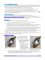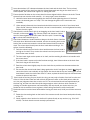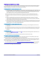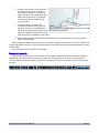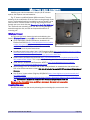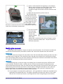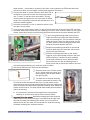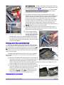
1
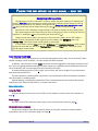
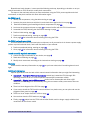
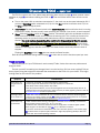
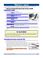
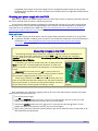
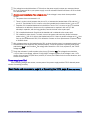
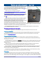
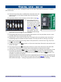
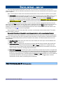
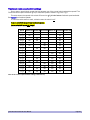
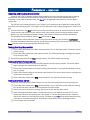
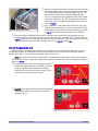
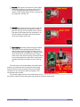
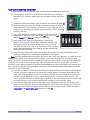
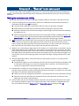
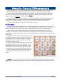
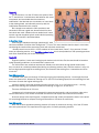
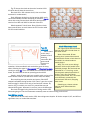
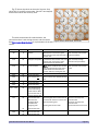
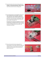
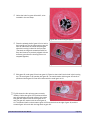
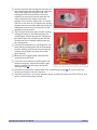
Hold the top half of the housing with the motor coil and armature gear over the bottom half. Insert the metal shaft on gear #2 through its hole in the housing top. Slide the top down the shaft and position it so the pins on one half mate with the holes on the other half. Squeeze the halves together firmly until their edges touch. You should hear four or five clicks as you squeeze the housing together around its perimeter. Squeeze around the housing two or three times to ensure that is tight together all the way around Fig. 64: Primary gears installed. Fig. 65 shows the primary gears in place, looking through the bottom of the closed housing. The armature gear meshes with gear #1. Transparent gear #3 is hard to see, and the tiny gear #4 that meshes with #2 is completely hidden under the time-setting knob. Connect the movement to an operating FCC4, and check that the primary gears and the time-setting knob are rotating. If not, disconnect and split the housing, then try again to position the primary gears correctly. When the primary gears rotate, disconnect the movement from the FCC4. If you chose to remove the secondary gears from the top housing half, replace them and the gear retainer, following the instructions and photos starting on page 42. Fig. 65: Housing bottom view, primary gears assembled. Place the movement into its square black case, as described on page 41. Be sure the wires are correctly positioned in the slot in the case. Install the movement in your clock, attach the hands, connect the clock to the FCC4 clock bus, and test for smooth and accurate running. FCC4 Fast Clock Controller User Manual Page 56